EP3074976B1 - Quadrature track error signal for optical recording media and devices - Google Patents
Quadrature track error signal for optical recording media and devices Download PDFInfo
- Publication number
- EP3074976B1 EP3074976B1 EP14784166.2A EP14784166A EP3074976B1 EP 3074976 B1 EP3074976 B1 EP 3074976B1 EP 14784166 A EP14784166 A EP 14784166A EP 3074976 B1 EP3074976 B1 EP 3074976B1
- Authority
- EP
- European Patent Office
- Prior art keywords
- signal
- error signal
- track error
- wobble
- motion
- Prior art date
- Legal status (The legal status is an assumption and is not a legal conclusion. Google has not performed a legal analysis and makes no representation as to the accuracy of the status listed.)
- Active
Links
Images


Classifications
-
- G—PHYSICS
- G11—INFORMATION STORAGE
- G11B—INFORMATION STORAGE BASED ON RELATIVE MOVEMENT BETWEEN RECORD CARRIER AND TRANSDUCER
- G11B7/00—Recording or reproducing by optical means, e.g. recording using a thermal beam of optical radiation by modifying optical properties or the physical structure, reproducing using an optical beam at lower power by sensing optical properties; Record carriers therefor
- G11B7/08—Disposition or mounting of heads or light sources relatively to record carriers
- G11B7/085—Disposition or mounting of heads or light sources relatively to record carriers with provision for moving the light beam into, or out of, its operative position or across tracks, otherwise than during the transducing operation, e.g. for adjustment or preliminary positioning or track change or selection
- G11B7/08505—Methods for track change, selection or preliminary positioning by moving the head
-
- G—PHYSICS
- G11—INFORMATION STORAGE
- G11B—INFORMATION STORAGE BASED ON RELATIVE MOVEMENT BETWEEN RECORD CARRIER AND TRANSDUCER
- G11B7/00—Recording or reproducing by optical means, e.g. recording using a thermal beam of optical radiation by modifying optical properties or the physical structure, reproducing using an optical beam at lower power by sensing optical properties; Record carriers therefor
- G11B7/08—Disposition or mounting of heads or light sources relatively to record carriers
- G11B7/09—Disposition or mounting of heads or light sources relatively to record carriers with provision for moving the light beam or focus plane for the purpose of maintaining alignment of the light beam relative to the record carrier during transducing operation, e.g. to compensate for surface irregularities of the latter or for track following
- G11B7/095—Disposition or mounting of heads or light sources relatively to record carriers with provision for moving the light beam or focus plane for the purpose of maintaining alignment of the light beam relative to the record carrier during transducing operation, e.g. to compensate for surface irregularities of the latter or for track following specially adapted for discs, e.g. for compensation of eccentricity or wobble
-
- G—PHYSICS
- G11—INFORMATION STORAGE
- G11B—INFORMATION STORAGE BASED ON RELATIVE MOVEMENT BETWEEN RECORD CARRIER AND TRANSDUCER
- G11B7/00—Recording or reproducing by optical means, e.g. recording using a thermal beam of optical radiation by modifying optical properties or the physical structure, reproducing using an optical beam at lower power by sensing optical properties; Record carriers therefor
- G11B7/004—Recording, reproducing or erasing methods; Read, write or erase circuits therefor
- G11B7/005—Reproducing
- G11B7/0053—Reproducing non-user data, e.g. wobbled address, prepits, BCA
Definitions
- the present invention is related to methods and apparatuses for detecting the movement of transducer heads in optical storage systems.
- Servo systems in optical data recording devices such as optical tape drives utilize tracking error signals, detected from the optical media via an optical pickup unit (OPU) device, to accurately record and then retrieve data on the optical media.
- OPU optical pickup unit
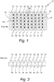
- Figures 1 and 2 illustrate a portion of a typical optical recording medium.
- FigurelA is a top view while Figure 1B is a side view.
- Optical recording media 10 includes a nanostructure surface relief pattern embossed on the surface of the optical medium.
- the nanostructure includes lands 12 and grooves 14 embossed in the Z direction (i.e., perpendicular to the face of optical recording medium 10) thereon in a preformatting process.
- These surface relief patterns are used to generate the tracking signals used by a servo system to track the position of an optical head reading or writing to the medium.
- An optical drive OPU with the aid electronic signal processing generates a tracking error signal (TES) from the detected patterns.
- TES tracking error signal
- edges of these embossed lands 12 and grooves 14 relief patterns are structurally modulated in the horizontal direction parallel to the face of optical recording medium 10 (e.g., Y axes to track X axes) with sinusoidal patterns 16 (i.e., wobbles) which contain individual track address codes.
- Figure 1A also depicts recording marks 18 encoded thereon.
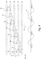
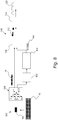
- FIG. 1 provides a schematic illustration of a typical signal processing scheme for the TES signal generated by the QPD.
- Signal processing system 20 includes recording/reading head 21.
- Recording/reading head 21 includes quad photodetector 22 which includes individual photodetectors 24, 26, 28, and 30. Signals 32, 34, 36, 38 from photodetectors 24, 26, 28, 30 are amplified by amplifiers 42, 44, 46, 48 to provide signals 52, 54, 56, 58. Signals 52, 54 are provided to adder 60 which outputs summed signal 62. Signals 56, 58 are provided to adder 64 which outputs summed signal 66. Summed signal 62 and summed signal 66 are inputted into subtractor circuit 70 with outputs difference signal 72 which is further processed to provide TES signal 78 and wobble signal 80.
- low pass filter 82 receives difference signal 72 as an input and outputs TES signal 78
- band pass filter 84 receives difference signal 72 and outputs wobble signal 80.
- the high frequency wobble signal includes, among other information, the key data track ID and Address codes.
- TES signal 78 and wobble signal 80 are used by recording/reading head servo system 86 to provide positioning information regarding the position of head 21.
- digital servo systems control the dynamic operation of the OPUs by using wobble signal information to place the OPU on the correct desired data track.
- the Radial Push Pull method of TES derivation generates a quantized sinusoidal signal as the OPU 22 moves across multiple data track on the media 10 along direction d 1 while the medium is moving along direction d tape .
- directional information is not provided by this method because of the quantized sinusoidal nature of the signal as depicted in Figure 5.
- Figure 5 demonstrates that movement first along direction d 1 and then along direction d 2 produces the same TES signal as movement only along direction d 1 . This lack of direction information has a severe impact on the robust control of the tracking servo system especially during cross track OPU motion. It is significant that the TES signals from both Figure 4 and 5 do not show any difference as OPU motion changes direction.
- US 2007/253293 relates to the identification of the direction of the relative movement between a scanning beam of an optical scanner and the tracks of optical storage media. Use is made of the fact that the amplitude of the component TW of a track error signal TE, said component being brought about by wobble of the tracks, is maximal in the track center and minimal in the region between the tracks. A signal TW is thus present which does not assume its maxima and minima across the scanning location x at the same places as the track error signal TE. Devices and methods are described for determining the movement direction DIR of the scanning beam from the phase shift between the two signals.
- the present invention solves one or more problems of the prior art, by providing a method for providing tracking error signals in an optical data storage system.
- the method generates signals that provide directional information on the motion of Optical Pickup Units across data tracks in optical recording media
- the optical data storage system includes a head having a wobble detection system.
- the method includes a step of receiving a wobble signal having a first frequency from the wobble detection system.
- the wobble detection system includes an optical pick up unit that detects positions of the head relative to lands and grooves.
- the wobble signal for the optical pick up unit centered on a land is 180 degrees out of phase with the wobble signal for the optical pick up unit centered on a groove.
- the wobble signal is amplitude modulated for positions intermediate between the land and the groove.
- the method further includes a step of receiving a primary tracking error signal from the wobble detection system.
- the wobble signal is multiplied with a synchronous signal to about a product signal.
- the product signal is positive for a first direction of motion and negative for a second direction of motion that is opposite that of the first direction.
- the product signal is integrated to obtain a quadrature track error signal.
- the quadrature track error signal is 90 degrees out of phase with the primary track error signal.
- the quadrature track error signal and the primary track error signal in combination and individually provide direction information about movement of the tape head across the width of the tape.
- an apparatus for implementing the method set forth above in which tracking error signals are provided in an optical storage system.
- the apparatus includes a transducer head having a wobble detection system.
- the wobble detection system includes an optical pick up unit that detects positions of the transducer head relative to lands and grooves and provides a wobble signal having a first frequency.
- the wobble signal for a land is amplitude modulated for positions intermediate between the land and the groove.
- a synchronous multiplier multiplies the wobble signal with a square wave signal having the first frequency to provide a product signal.
- the product signal is positive for a first direction of motion and negative for a second direction of motion that is opposite that of the first direction.
- An integrator integrates the product signal to obtain a quadrature track error signal.
- the quadrature track error signal being 90 degrees out of phase with the track error signal, the quadrature track error signal and the track error signal in combination provide direction information about movement of the transducer head across data tracks.
- Embodiments and variations of the invention advantageously utilize wobble signal information from a digital data storage media to generate a novel complimentary Quadrature Track Error Signal (QTES) that provides the directions of OPU motion information.
- QTES Quadrature Track Error Signal
- a system such as that described by Figure 3 is utilized to provide a wobble signal.
- Methods for detecting wobble signals and/or Tracking Error Signals are set forth in U.S. Pat. Nos. 5,383,169 ; 6,009059 ; and 6,937,542 ; the entire disclosures of which are hereby incorporated by reference.
- the QTES signal allows robust control of OPU motion by allowing in combination detection of the movement of the recording head.
- Figure 6A provides an example of a wobble signal obtained when the OPU is centered on a groove while Figure 6B provides an example of a wobble signal when the OPU is centered on a land.
- the wobble signals are the result of the wobbled edge structure of the grooved tracks at very high spatial frequency with narrow high frequency band passing filtering of MPP.
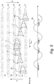
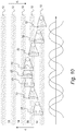
- Figure 7 provides a schematic showing the evolution of a wobble signal as OPU 22 moves across the data tracks of optical storage medium 10. Due to the properties of the diffraction pattern generated by the land and groove media surface structure, the polarity of the wobble signals changes as OPU 22 moves along direction d 1 and medium 10 moves along direction d tape .
- the wobble signal is described by item number 90.
- the wobble signal amplitude modulates until the OPU is centered on a land, at which point the wobble signal is described by item number 92.
- the amplitude of wobble signal 78 has an intermediate value.
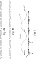
- Optical data storage system 100 includes transducer head 102 in communication with a wobble detection system 104.
- Wobble detection system 104 includes optical pick up unit 22 that detects positions of the transducer head relative to lands and grooves as set forth above with respect to the descriptions of Figures 1-3 .
- Optical pick up unit 22 is positioned in transducer head 102.
- the wobble detection system of Figure 2 is used in this embodiment.
- Wobble detection system 104 provides direct track error signal 78 and wobble signal 80.
- the term direct track error signal 78 refers to the normal prior art track error signal that is detected by the "Main Push Pull" (MPP) method or the differential push pull method.
- Wobble signal 80 is characterized by having a first frequency (i.e., a wobble signal frequency). In a refinement, the wobble signal frequency is from 0.5 megahertz to 10 megahertz. Typical wobble signal frequencies are about 1 megahertz.
- wobble signal 80 for a land is 180 degrees out of phase with the wobble signal for a groove with wobble signal 80 being amplitude modulated for positions intermediate between the land and the groove.
- being 180 out of phase means that wobble signal peaks maxima for lands correspond to wobble signal minima for grooves and wobble signal peaks minima for lands correspond to wobble signal maxima for grooves.
- Synchronous multiplier 106 multiplies wobble signal 80 with square wave 108 signal derived from synchronous clock 110 having the first frequency to provide a product signal 112.
- square wave 108 has a voltage amplitude varying from 0 volts to a peak value (e.g. 1 volt).
- Product signal 112 is positive for a first direction of motion of transducer head 102 and negative for a second direction of motion of transducer head 102 that is opposite that of the first direction.
- Integrator 114 integrates the product signal 112 to obtain quadrature track error signal 120. Characteristically, quadrature track error signal 120 is 90 degrees out of phase with the track error signal. Quadrature track error signal (QTES) and the track error signal 78 in combination provide direction information about movement of the transducer head across data tracks as set forth below.
- QTES Quadrature track error signal
- the track error signal 78 in combination provide direction information about movement of the transducer head across data tracks as set forth below.
- Optical storage system 100 also includes phase lock loop 122 which allows square wave 108 to lock onto wobble signal 80.
- Phase lock loop 122 receives the appropriate locking frequency from wobble signal 80.
- Phase lock loop 122 is phase adjustable to maximize product signal 112.
- the direct track error signal leads the quadrature track error signal for the first direction of motion d 1 .
- the quadrature track error signal leads the direct track error signal for the second direction of motion d 2 .
- quadrature track error signal 120 changes such that the product signal 112 is positive for first direction of motion d 1 and negative for second direction of motion d 2 that is opposite that of the first direction.
- direct track error signal 80 includes a first set of regions that are approximated by linear functions l 1 and quadrature track error signal 12 includes a second set of regions that are approximated by linear functions l 2 .
- the first set of regions that are approximated by linear functions and the second set of regions that are approximated by linear functions include non-overlapping portions with respect to displacement of the transducer head from a land or groove. Moreover, the first set of regions that are approximated by linear functions and the second set of regions that are approximated by linear functions provide complete linearization of the motion of the transducer head across the data tracks.
- step a) wobble signal 80 having a first frequency is received from a wobble detection system 104 such as the system depicted in Figure 2 .
- the wobble detection system includes an optical pick up unit that detects positions of a transducer head relative to lands and grooves.
- Wobble signal 80 for the optical pick up unit centered on a land is 180 degrees out of phase with the wobble signal for the optical pick up unit centered on a groove.
- the wobble signal is amplitude modulated for positions intermediate between the land and the groove.
- step b) a direct tracking error signal 78 from the wobble detection system is received.
- step c) wobble signal 80 is multiplied with a synchronous signal to about product signal 112.
- Product signal 112 is positive for a first direction of motion and negative for a second direction of motion that is opposite that of the first direction.
- step d) product signal 112 is integrated to obtain quadrature track error signal 120.
- the quadrature track error signal is 90 degrees out of phase with the primary track error signal.
- the quadrature track error signal and the primary track error signal in combination and individually provide direction information about movement of the tape head across the width of the tape as set forth above.
- TES signal 78 and wobble signal 80 are used by recording/reading head servo system 86 to provide positioning information regarding the position of the transducer head.
- digital servo systems controls the dynamic operation of the OPUs by using wobble signal information to place the OPU on the correct desired data track.
Landscapes
- Optical Recording Or Reproduction (AREA)
Applications Claiming Priority (2)
| Application Number | Priority Date | Filing Date | Title |
|---|---|---|---|
| US14/090,240 US9734859B2 (en) | 2013-11-26 | 2013-11-26 | Quadrature track error signal for optical recording media and devices |
| PCT/US2014/057594 WO2015080794A1 (en) | 2013-11-26 | 2014-09-26 | Quadrature track error signal for optical recording media and devices |
Publications (2)
| Publication Number | Publication Date |
|---|---|
| EP3074976A1 EP3074976A1 (en) | 2016-10-05 |
| EP3074976B1 true EP3074976B1 (en) | 2019-11-13 |
Family
ID=51703413
Family Applications (1)
| Application Number | Title | Priority Date | Filing Date |
|---|---|---|---|
| EP14784166.2A Active EP3074976B1 (en) | 2013-11-26 | 2014-09-26 | Quadrature track error signal for optical recording media and devices |
Country Status (7)
| Country | Link |
|---|---|
| US (2) | US9734859B2 (enExample) |
| EP (1) | EP3074976B1 (enExample) |
| JP (1) | JP6321157B2 (enExample) |
| CN (1) | CN105612579B (enExample) |
| AU (1) | AU2014355132B2 (enExample) |
| NZ (1) | NZ718003A (enExample) |
| WO (1) | WO2015080794A1 (enExample) |
Family Cites Families (23)
| Publication number | Priority date | Publication date | Assignee | Title |
|---|---|---|---|---|
| DE2963133D1 (en) * | 1978-01-18 | 1982-08-12 | Rca Corp | Chroma demodulator circuit for secam television signals |
| JPH01223634A (ja) * | 1988-03-02 | 1989-09-06 | Hitachi Ltd | 光学的情報記録媒体および記録再生装置 |
| US4914725A (en) * | 1989-07-10 | 1990-04-03 | International Business Machines Corporation | Transducer positioning servo mechanisms employing digital and analog circuits |
| JP2710704B2 (ja) * | 1991-07-08 | 1998-02-10 | シャープ株式会社 | 光記録媒体駆動装置 |
| KR950010418B1 (ko) | 1991-08-28 | 1995-09-16 | 미쯔비시덴끼 가부시끼가이샤 | 광기록재생장치 |
| JPH1069640A (ja) | 1996-08-27 | 1998-03-10 | Mitsumi Electric Co Ltd | Cd−rドライブにおけるウォブル信号生成方法 |
| FR2755808B1 (fr) * | 1996-11-14 | 1999-01-08 | Alsthom Cge Alcatel | Estimateur d'un defaut de fonctionnement d'un modulateur en quadrature et etage de modulation l'utilisant |
| ID26570A (id) * | 1999-01-25 | 2001-01-18 | Koninkl Philips Electronics Nv | Pembawa rekaman dan perangkat untuk menscanning pembawa rekamannya |
| JP3503513B2 (ja) | 1999-02-22 | 2004-03-08 | ヤマハ株式会社 | 光ディスク記録方法及び装置 |
| JP2001006182A (ja) * | 1999-06-22 | 2001-01-12 | Matsushita Electric Ind Co Ltd | 光記録媒体および方向検出装置 |
| US6473369B1 (en) | 1999-12-23 | 2002-10-29 | Oak Technology, Inc. | Methods and apparatus for regenerating track crossing signals for searches across unrecorded areas on read/write optical discs |
| US7260031B2 (en) * | 2001-01-25 | 2007-08-21 | Dphi Acquisitions, Inc. | Digital focus and tracking servo system with one-track jump |
| US6744712B2 (en) * | 2001-01-29 | 2004-06-01 | Hewlett-Packard Development Company, L.P. | Optical disc drive with satellite beams for generation of quadrature error signals for radial position detection |
| JP4232428B2 (ja) | 2002-10-10 | 2009-03-04 | パナソニック株式会社 | 光ディスクのトラッキング制御装置および方法 |
| DE102004019692A1 (de) | 2004-04-20 | 2005-11-10 | Deutsche Thomson-Brandt Gmbh | Verfahren und Vorrichtung für das Spurzählen bei optischen Aufzeichnungsträgern |
| JP2005346745A (ja) * | 2004-05-31 | 2005-12-15 | Toshiba Corp | ディスクドライブ装置及びピックアップ位置制御方法 |
| US7804746B2 (en) | 2005-03-11 | 2010-09-28 | Mediatek Inc. | Land/groove track and pickup head movement direction detection |
| JP2007225500A (ja) * | 2006-02-24 | 2007-09-06 | Denso Corp | 距離測定方法及び装置 |
| US8054715B1 (en) * | 2006-03-20 | 2011-11-08 | Marvell International Ltd. | Track counting system and method for recordable optical media |
| US7742373B2 (en) * | 2007-07-06 | 2010-06-22 | Lite-On It Corporation | Optical disk drive for scanning an optical disk carrying a groove with a wobble |
| US7821885B2 (en) | 2007-10-30 | 2010-10-26 | Mediatek Inc. | TE signal polarity determining system and related method thereof |
| JP5623948B2 (ja) * | 2011-03-24 | 2014-11-12 | 日立コンシューマエレクトロニクス株式会社 | 推奨記録条件の決定方法及び記録調整方法 |
| JP2013065363A (ja) * | 2011-09-15 | 2013-04-11 | Sony Corp | 光記録媒体、記録装置、記録方法 |
-
2013
- 2013-11-26 US US14/090,240 patent/US9734859B2/en active Active
-
2014
- 2014-09-26 EP EP14784166.2A patent/EP3074976B1/en active Active
- 2014-09-26 AU AU2014355132A patent/AU2014355132B2/en active Active
- 2014-09-26 JP JP2016524081A patent/JP6321157B2/ja active Active
- 2014-09-26 CN CN201480055502.2A patent/CN105612579B/zh active Active
- 2014-09-26 NZ NZ718003A patent/NZ718003A/en unknown
- 2014-09-26 WO PCT/US2014/057594 patent/WO2015080794A1/en not_active Ceased
-
2017
- 2017-05-19 US US15/600,624 patent/US10079037B2/en active Active
Non-Patent Citations (1)
| Title |
|---|
| None * |
Also Published As
| Publication number | Publication date |
|---|---|
| US20170256279A1 (en) | 2017-09-07 |
| EP3074976A1 (en) | 2016-10-05 |
| JP6321157B2 (ja) | 2018-05-09 |
| CN105612579B (zh) | 2019-02-01 |
| US9734859B2 (en) | 2017-08-15 |
| AU2014355132B2 (en) | 2019-09-12 |
| US10079037B2 (en) | 2018-09-18 |
| JP2017500680A (ja) | 2017-01-05 |
| CN105612579A (zh) | 2016-05-25 |
| NZ718003A (en) | 2020-06-26 |
| US20150146509A1 (en) | 2015-05-28 |
| AU2014355132A1 (en) | 2016-03-10 |
| WO2015080794A1 (en) | 2015-06-04 |
Similar Documents
| Publication | Publication Date | Title |
|---|---|---|
| DE69737979T2 (de) | Plattenaufzeichnungs- Plattenwiedergabevorrichtung | |
| US8786979B1 (en) | Self servo write process for discrete track media | |
| US9218839B2 (en) | Operating a tape storage device | |
| US4488188A (en) | Buried servo recording system using phase encoded servo pattern | |
| US5197058A (en) | Electronic offset compensation of the continuous composite track error signal in optical recording | |
| US7623317B2 (en) | Magnetic disk device and magnetic recording medium | |
| EP3074976B1 (en) | Quadrature track error signal for optical recording media and devices | |
| US20150287429A1 (en) | Systems and methods for determining a position error of a read/write head | |
| EP2939237B1 (en) | Optical media servo tracking | |
| US20040008597A1 (en) | Light spot advancing direction judging device and method, optical head device control device and method, and optical disk recording/reproducing device | |
| US5625508A (en) | Method and apparatus for servo demodulation in a direct access storage device | |
| US8054715B1 (en) | Track counting system and method for recordable optical media | |
| US9336812B1 (en) | Adaptive control of tracking servo system of optical heads in optical storage devices | |
| JPH01277361A (ja) | データ記録装置 | |
| JP2008176909A (ja) | 記録再生装置及び記録媒体。 | |
| Cherubini et al. | High-Rate Skew Estimation for Tape Systems | |
| JP2009037700A (ja) | 磁気記録媒体 | |
| JPH04252415A (ja) | 磁気ディスクおよび磁気ディスク装置 | |
| JP2008065935A (ja) | ディスク記録媒体および情報記録装置 | |
| JPH0997433A (ja) | 光ディスク,光ディスクの記録再生装置および光ディスクの記録再生方法 |
Legal Events
| Date | Code | Title | Description |
|---|---|---|---|
| PUAI | Public reference made under article 153(3) epc to a published international application that has entered the european phase |
Free format text: ORIGINAL CODE: 0009012 |
|
| 17P | Request for examination filed |
Effective date: 20160516 |
|
| AK | Designated contracting states |
Kind code of ref document: A1 Designated state(s): AL AT BE BG CH CY CZ DE DK EE ES FI FR GB GR HR HU IE IS IT LI LT LU LV MC MK MT NL NO PL PT RO RS SE SI SK SM TR |
|
| AX | Request for extension of the european patent |
Extension state: BA ME |
|
| DAX | Request for extension of the european patent (deleted) | ||
| STAA | Information on the status of an ep patent application or granted ep patent |
Free format text: STATUS: EXAMINATION IS IN PROGRESS |
|
| 17Q | First examination report despatched |
Effective date: 20170614 |
|
| GRAP | Despatch of communication of intention to grant a patent |
Free format text: ORIGINAL CODE: EPIDOSNIGR1 |
|
| STAA | Information on the status of an ep patent application or granted ep patent |
Free format text: STATUS: GRANT OF PATENT IS INTENDED |
|
| RAP1 | Party data changed (applicant data changed or rights of an application transferred) |
Owner name: ORACLE INTERNATIONAL CORPORATION |
|
| INTG | Intention to grant announced |
Effective date: 20190605 |
|
| GRAS | Grant fee paid |
Free format text: ORIGINAL CODE: EPIDOSNIGR3 |
|
| GRAA | (expected) grant |
Free format text: ORIGINAL CODE: 0009210 |
|
| STAA | Information on the status of an ep patent application or granted ep patent |
Free format text: STATUS: THE PATENT HAS BEEN GRANTED |
|
| AK | Designated contracting states |
Kind code of ref document: B1 Designated state(s): AL AT BE BG CH CY CZ DE DK EE ES FI FR GB GR HR HU IE IS IT LI LT LU LV MC MK MT NL NO PL PT RO RS SE SI SK SM TR |
|
| REG | Reference to a national code |
Ref country code: CH Ref legal event code: EP Ref country code: AT Ref legal event code: REF Ref document number: 1202501 Country of ref document: AT Kind code of ref document: T Effective date: 20191115 |
|
| REG | Reference to a national code |
Ref country code: DE Ref legal event code: R096 Ref document number: 602014056813 Country of ref document: DE |
|
| REG | Reference to a national code |
Ref country code: IE Ref legal event code: FG4D |
|
| REG | Reference to a national code |
Ref country code: NL Ref legal event code: MP Effective date: 20191113 |
|
| REG | Reference to a national code |
Ref country code: LT Ref legal event code: MG4D |
|
| PG25 | Lapsed in a contracting state [announced via postgrant information from national office to epo] |
Ref country code: FI Free format text: LAPSE BECAUSE OF FAILURE TO SUBMIT A TRANSLATION OF THE DESCRIPTION OR TO PAY THE FEE WITHIN THE PRESCRIBED TIME-LIMIT Effective date: 20191113 Ref country code: BG Free format text: LAPSE BECAUSE OF FAILURE TO SUBMIT A TRANSLATION OF THE DESCRIPTION OR TO PAY THE FEE WITHIN THE PRESCRIBED TIME-LIMIT Effective date: 20200213 Ref country code: GR Free format text: LAPSE BECAUSE OF FAILURE TO SUBMIT A TRANSLATION OF THE DESCRIPTION OR TO PAY THE FEE WITHIN THE PRESCRIBED TIME-LIMIT Effective date: 20200214 Ref country code: PL Free format text: LAPSE BECAUSE OF FAILURE TO SUBMIT A TRANSLATION OF THE DESCRIPTION OR TO PAY THE FEE WITHIN THE PRESCRIBED TIME-LIMIT Effective date: 20191113 Ref country code: NO Free format text: LAPSE BECAUSE OF FAILURE TO SUBMIT A TRANSLATION OF THE DESCRIPTION OR TO PAY THE FEE WITHIN THE PRESCRIBED TIME-LIMIT Effective date: 20200213 Ref country code: SE Free format text: LAPSE BECAUSE OF FAILURE TO SUBMIT A TRANSLATION OF THE DESCRIPTION OR TO PAY THE FEE WITHIN THE PRESCRIBED TIME-LIMIT Effective date: 20191113 Ref country code: PT Free format text: LAPSE BECAUSE OF FAILURE TO SUBMIT A TRANSLATION OF THE DESCRIPTION OR TO PAY THE FEE WITHIN THE PRESCRIBED TIME-LIMIT Effective date: 20200313 Ref country code: LV Free format text: LAPSE BECAUSE OF FAILURE TO SUBMIT A TRANSLATION OF THE DESCRIPTION OR TO PAY THE FEE WITHIN THE PRESCRIBED TIME-LIMIT Effective date: 20191113 Ref country code: LT Free format text: LAPSE BECAUSE OF FAILURE TO SUBMIT A TRANSLATION OF THE DESCRIPTION OR TO PAY THE FEE WITHIN THE PRESCRIBED TIME-LIMIT Effective date: 20191113 Ref country code: NL Free format text: LAPSE BECAUSE OF FAILURE TO SUBMIT A TRANSLATION OF THE DESCRIPTION OR TO PAY THE FEE WITHIN THE PRESCRIBED TIME-LIMIT Effective date: 20191113 |
|
| PG25 | Lapsed in a contracting state [announced via postgrant information from national office to epo] |
Ref country code: IS Free format text: LAPSE BECAUSE OF FAILURE TO SUBMIT A TRANSLATION OF THE DESCRIPTION OR TO PAY THE FEE WITHIN THE PRESCRIBED TIME-LIMIT Effective date: 20200313 Ref country code: RS Free format text: LAPSE BECAUSE OF FAILURE TO SUBMIT A TRANSLATION OF THE DESCRIPTION OR TO PAY THE FEE WITHIN THE PRESCRIBED TIME-LIMIT Effective date: 20191113 Ref country code: HR Free format text: LAPSE BECAUSE OF FAILURE TO SUBMIT A TRANSLATION OF THE DESCRIPTION OR TO PAY THE FEE WITHIN THE PRESCRIBED TIME-LIMIT Effective date: 20191113 |
|
| PG25 | Lapsed in a contracting state [announced via postgrant information from national office to epo] |
Ref country code: AL Free format text: LAPSE BECAUSE OF FAILURE TO SUBMIT A TRANSLATION OF THE DESCRIPTION OR TO PAY THE FEE WITHIN THE PRESCRIBED TIME-LIMIT Effective date: 20191113 |
|
| PG25 | Lapsed in a contracting state [announced via postgrant information from national office to epo] |
Ref country code: DK Free format text: LAPSE BECAUSE OF FAILURE TO SUBMIT A TRANSLATION OF THE DESCRIPTION OR TO PAY THE FEE WITHIN THE PRESCRIBED TIME-LIMIT Effective date: 20191113 Ref country code: ES Free format text: LAPSE BECAUSE OF FAILURE TO SUBMIT A TRANSLATION OF THE DESCRIPTION OR TO PAY THE FEE WITHIN THE PRESCRIBED TIME-LIMIT Effective date: 20191113 Ref country code: EE Free format text: LAPSE BECAUSE OF FAILURE TO SUBMIT A TRANSLATION OF THE DESCRIPTION OR TO PAY THE FEE WITHIN THE PRESCRIBED TIME-LIMIT Effective date: 20191113 Ref country code: RO Free format text: LAPSE BECAUSE OF FAILURE TO SUBMIT A TRANSLATION OF THE DESCRIPTION OR TO PAY THE FEE WITHIN THE PRESCRIBED TIME-LIMIT Effective date: 20191113 Ref country code: CZ Free format text: LAPSE BECAUSE OF FAILURE TO SUBMIT A TRANSLATION OF THE DESCRIPTION OR TO PAY THE FEE WITHIN THE PRESCRIBED TIME-LIMIT Effective date: 20191113 |
|
| REG | Reference to a national code |
Ref country code: DE Ref legal event code: R097 Ref document number: 602014056813 Country of ref document: DE |
|
| REG | Reference to a national code |
Ref country code: AT Ref legal event code: MK05 Ref document number: 1202501 Country of ref document: AT Kind code of ref document: T Effective date: 20191113 |
|
| PG25 | Lapsed in a contracting state [announced via postgrant information from national office to epo] |
Ref country code: SM Free format text: LAPSE BECAUSE OF FAILURE TO SUBMIT A TRANSLATION OF THE DESCRIPTION OR TO PAY THE FEE WITHIN THE PRESCRIBED TIME-LIMIT Effective date: 20191113 Ref country code: SK Free format text: LAPSE BECAUSE OF FAILURE TO SUBMIT A TRANSLATION OF THE DESCRIPTION OR TO PAY THE FEE WITHIN THE PRESCRIBED TIME-LIMIT Effective date: 20191113 |
|
| PLBE | No opposition filed within time limit |
Free format text: ORIGINAL CODE: 0009261 |
|
| STAA | Information on the status of an ep patent application or granted ep patent |
Free format text: STATUS: NO OPPOSITION FILED WITHIN TIME LIMIT |
|
| 26N | No opposition filed |
Effective date: 20200814 |
|
| PG25 | Lapsed in a contracting state [announced via postgrant information from national office to epo] |
Ref country code: AT Free format text: LAPSE BECAUSE OF FAILURE TO SUBMIT A TRANSLATION OF THE DESCRIPTION OR TO PAY THE FEE WITHIN THE PRESCRIBED TIME-LIMIT Effective date: 20191113 Ref country code: SI Free format text: LAPSE BECAUSE OF FAILURE TO SUBMIT A TRANSLATION OF THE DESCRIPTION OR TO PAY THE FEE WITHIN THE PRESCRIBED TIME-LIMIT Effective date: 20191113 |
|
| PG25 | Lapsed in a contracting state [announced via postgrant information from national office to epo] |
Ref country code: IT Free format text: LAPSE BECAUSE OF FAILURE TO SUBMIT A TRANSLATION OF THE DESCRIPTION OR TO PAY THE FEE WITHIN THE PRESCRIBED TIME-LIMIT Effective date: 20191113 |
|
| PG25 | Lapsed in a contracting state [announced via postgrant information from national office to epo] |
Ref country code: MC Free format text: LAPSE BECAUSE OF FAILURE TO SUBMIT A TRANSLATION OF THE DESCRIPTION OR TO PAY THE FEE WITHIN THE PRESCRIBED TIME-LIMIT Effective date: 20191113 |
|
| REG | Reference to a national code |
Ref country code: CH Ref legal event code: PL |
|
| REG | Reference to a national code |
Ref country code: BE Ref legal event code: MM Effective date: 20200930 |
|
| PG25 | Lapsed in a contracting state [announced via postgrant information from national office to epo] |
Ref country code: LU Free format text: LAPSE BECAUSE OF NON-PAYMENT OF DUE FEES Effective date: 20200926 |
|
| PG25 | Lapsed in a contracting state [announced via postgrant information from national office to epo] |
Ref country code: FR Free format text: LAPSE BECAUSE OF NON-PAYMENT OF DUE FEES Effective date: 20200930 |
|
| PG25 | Lapsed in a contracting state [announced via postgrant information from national office to epo] |
Ref country code: LI Free format text: LAPSE BECAUSE OF NON-PAYMENT OF DUE FEES Effective date: 20200930 Ref country code: IE Free format text: LAPSE BECAUSE OF NON-PAYMENT OF DUE FEES Effective date: 20200926 Ref country code: CH Free format text: LAPSE BECAUSE OF NON-PAYMENT OF DUE FEES Effective date: 20200930 Ref country code: BE Free format text: LAPSE BECAUSE OF NON-PAYMENT OF DUE FEES Effective date: 20200930 |
|
| PG25 | Lapsed in a contracting state [announced via postgrant information from national office to epo] |
Ref country code: TR Free format text: LAPSE BECAUSE OF FAILURE TO SUBMIT A TRANSLATION OF THE DESCRIPTION OR TO PAY THE FEE WITHIN THE PRESCRIBED TIME-LIMIT Effective date: 20191113 Ref country code: MT Free format text: LAPSE BECAUSE OF FAILURE TO SUBMIT A TRANSLATION OF THE DESCRIPTION OR TO PAY THE FEE WITHIN THE PRESCRIBED TIME-LIMIT Effective date: 20191113 Ref country code: CY Free format text: LAPSE BECAUSE OF FAILURE TO SUBMIT A TRANSLATION OF THE DESCRIPTION OR TO PAY THE FEE WITHIN THE PRESCRIBED TIME-LIMIT Effective date: 20191113 |
|
| PG25 | Lapsed in a contracting state [announced via postgrant information from national office to epo] |
Ref country code: MK Free format text: LAPSE BECAUSE OF FAILURE TO SUBMIT A TRANSLATION OF THE DESCRIPTION OR TO PAY THE FEE WITHIN THE PRESCRIBED TIME-LIMIT Effective date: 20191113 |
|
| P01 | Opt-out of the competence of the unified patent court (upc) registered |
Effective date: 20230522 |
|
| PGFP | Annual fee paid to national office [announced via postgrant information from national office to epo] |
Ref country code: DE Payment date: 20250730 Year of fee payment: 12 |
|
| PGFP | Annual fee paid to national office [announced via postgrant information from national office to epo] |
Ref country code: GB Payment date: 20250807 Year of fee payment: 12 |