EP3074252B1 - Frischluftkontrolle für eine transportkühleinheit - Google Patents
Frischluftkontrolle für eine transportkühleinheit Download PDFInfo
- Publication number
- EP3074252B1 EP3074252B1 EP14863536.0A EP14863536A EP3074252B1 EP 3074252 B1 EP3074252 B1 EP 3074252B1 EP 14863536 A EP14863536 A EP 14863536A EP 3074252 B1 EP3074252 B1 EP 3074252B1
- Authority
- EP
- European Patent Office
- Prior art keywords
- fresh air
- evaporator fan
- temperature
- passenger compartment
- set point
- Prior art date
- Legal status (The legal status is an assumption and is not a legal conclusion. Google has not performed a legal analysis and makes no representation as to the accuracy of the status listed.)
- Active
Links
- 238000005057 refrigeration Methods 0.000 title description 2
- 238000000034 method Methods 0.000 claims description 38
- 238000010438 heat treatment Methods 0.000 claims description 19
- CURLTUGMZLYLDI-UHFFFAOYSA-N Carbon dioxide Chemical compound O=C=O CURLTUGMZLYLDI-UHFFFAOYSA-N 0.000 claims description 12
- 238000004378 air conditioning Methods 0.000 claims description 11
- 238000012544 monitoring process Methods 0.000 claims description 9
- 230000004044 response Effects 0.000 claims description 8
- 238000009423 ventilation Methods 0.000 claims description 8
- 229910002092 carbon dioxide Inorganic materials 0.000 claims description 6
- 239000001569 carbon dioxide Substances 0.000 claims description 6
- 230000007423 decrease Effects 0.000 claims description 3
- 230000003247 decreasing effect Effects 0.000 claims 4
- 239000003570 air Substances 0.000 description 157
- 238000001816 cooling Methods 0.000 description 15
- 230000001143 conditioned effect Effects 0.000 description 12
- 238000004140 cleaning Methods 0.000 description 10
- 238000005259 measurement Methods 0.000 description 9
- 239000012855 volatile organic compound Substances 0.000 description 7
- 230000007613 environmental effect Effects 0.000 description 5
- 239000000428 dust Substances 0.000 description 4
- 239000000446 fuel Substances 0.000 description 4
- 239000012080 ambient air Substances 0.000 description 3
- 230000006870 function Effects 0.000 description 3
- 239000000356 contaminant Substances 0.000 description 2
- 238000010586 diagram Methods 0.000 description 2
- 238000001914 filtration Methods 0.000 description 2
- 239000002245 particle Substances 0.000 description 2
- 238000002485 combustion reaction Methods 0.000 description 1
- 238000004891 communication Methods 0.000 description 1
- 238000004088 simulation Methods 0.000 description 1
- 238000012360 testing method Methods 0.000 description 1
Images


Classifications
-
- B—PERFORMING OPERATIONS; TRANSPORTING
- B60—VEHICLES IN GENERAL
- B60H—ARRANGEMENTS OF HEATING, COOLING, VENTILATING OR OTHER AIR-TREATING DEVICES SPECIALLY ADAPTED FOR PASSENGER OR GOODS SPACES OF VEHICLES
- B60H1/00—Heating, cooling or ventilating [HVAC] devices
- B60H1/00642—Control systems or circuits; Control members or indication devices for heating, cooling or ventilating devices
- B60H1/00814—Control systems or circuits characterised by their output, for controlling particular components of the heating, cooling or ventilating installation
- B60H1/00821—Control systems or circuits characterised by their output, for controlling particular components of the heating, cooling or ventilating installation the components being ventilating, air admitting or air distributing devices
- B60H1/00835—Damper doors, e.g. position control
- B60H1/00849—Damper doors, e.g. position control for selectively commanding the induction of outside or inside air
-
- B—PERFORMING OPERATIONS; TRANSPORTING
- B60—VEHICLES IN GENERAL
- B60H—ARRANGEMENTS OF HEATING, COOLING, VENTILATING OR OTHER AIR-TREATING DEVICES SPECIALLY ADAPTED FOR PASSENGER OR GOODS SPACES OF VEHICLES
- B60H1/00—Heating, cooling or ventilating [HVAC] devices
- B60H1/00357—Air-conditioning arrangements specially adapted for particular vehicles
- B60H1/00371—Air-conditioning arrangements specially adapted for particular vehicles for vehicles carrying large numbers of passengers, e.g. buses
-
- B—PERFORMING OPERATIONS; TRANSPORTING
- B60—VEHICLES IN GENERAL
- B60H—ARRANGEMENTS OF HEATING, COOLING, VENTILATING OR OTHER AIR-TREATING DEVICES SPECIALLY ADAPTED FOR PASSENGER OR GOODS SPACES OF VEHICLES
- B60H1/00—Heating, cooling or ventilating [HVAC] devices
- B60H1/00642—Control systems or circuits; Control members or indication devices for heating, cooling or ventilating devices
- B60H1/00735—Control systems or circuits characterised by their input, i.e. by the detection, measurement or calculation of particular conditions, e.g. signal treatment, dynamic models
- B60H1/008—Control systems or circuits characterised by their input, i.e. by the detection, measurement or calculation of particular conditions, e.g. signal treatment, dynamic models the input being air quality
-
- B—PERFORMING OPERATIONS; TRANSPORTING
- B60—VEHICLES IN GENERAL
- B60H—ARRANGEMENTS OF HEATING, COOLING, VENTILATING OR OTHER AIR-TREATING DEVICES SPECIALLY ADAPTED FOR PASSENGER OR GOODS SPACES OF VEHICLES
- B60H1/00—Heating, cooling or ventilating [HVAC] devices
- B60H1/00642—Control systems or circuits; Control members or indication devices for heating, cooling or ventilating devices
- B60H1/00814—Control systems or circuits characterised by their output, for controlling particular components of the heating, cooling or ventilating installation
- B60H1/00821—Control systems or circuits characterised by their output, for controlling particular components of the heating, cooling or ventilating installation the components being ventilating, air admitting or air distributing devices
- B60H1/00828—Ventilators, e.g. speed control
-
- B—PERFORMING OPERATIONS; TRANSPORTING
- B60—VEHICLES IN GENERAL
- B60H—ARRANGEMENTS OF HEATING, COOLING, VENTILATING OR OTHER AIR-TREATING DEVICES SPECIALLY ADAPTED FOR PASSENGER OR GOODS SPACES OF VEHICLES
- B60H1/00—Heating, cooling or ventilating [HVAC] devices
- B60H1/00642—Control systems or circuits; Control members or indication devices for heating, cooling or ventilating devices
- B60H1/00814—Control systems or circuits characterised by their output, for controlling particular components of the heating, cooling or ventilating installation
- B60H1/00821—Control systems or circuits characterised by their output, for controlling particular components of the heating, cooling or ventilating installation the components being ventilating, air admitting or air distributing devices
- B60H1/00864—Ventilators and damper doors
-
- B—PERFORMING OPERATIONS; TRANSPORTING
- B60—VEHICLES IN GENERAL
- B60H—ARRANGEMENTS OF HEATING, COOLING, VENTILATING OR OTHER AIR-TREATING DEVICES SPECIALLY ADAPTED FOR PASSENGER OR GOODS SPACES OF VEHICLES
- B60H1/00—Heating, cooling or ventilating [HVAC] devices
- B60H1/32—Cooling devices
- B60H2001/3269—Cooling devices output of a control signal
- B60H2001/328—Cooling devices output of a control signal related to an evaporating unit
- B60H2001/3282—Cooling devices output of a control signal related to an evaporating unit to control the air flow
Definitions
- the invention relates generally to a heating, ventilation, and air conditioning (HVAC) system in a transport vehicle. More specifically, the embodiments relate to a system and method for controlling fresh air intake in an HVAC system of a transport vehicle.
- HVAC heating, ventilation, and air conditioning
- An HVAC system such as an air conditioning system for a transport vehicle (e.g., a passenger bus, passenger railcar, etc.), may be included on a transport vehicle to condition air of an interior space (e.g., passenger compartment) of the transport vehicle.
- the transport HVAC system can be installed externally (e.g., on a rooftop of the transport vehicle).
- the transport HVAC system can include a fresh air intake to input fresh air into the interior space of the transport vehicle.
- the transport HVAC system can also be configured to return air that is not fresh to the environment.
- US4391320 discloses a method for air conditioning vehicles comprising detecting a temperature of a passenger compartment of a vehicle, an atmospheric temperature and a preset temperature in the initial period of air conditioning, judging the results of comparisons between said temperatures and switching between air conditioning by the circulation of inside air and outside air.
- the invention relates generally to an HVAC system in a transport vehicle. More specifically, the embodiments relate to a system and method for controlling fresh air intake in an HVAC system of a transport vehicle.
- a transport vehicle includes a passenger bus. In some embodiments, a transport vehicle includes a passenger railcar. In some embodiments, a transport vehicle includes other types of passenger vehicles, such as ships, airplanes, etc.
- an evaporator fan in a high speed mode when a fresh air damper is in an open position, even when a passenger compartment of a transport vehicle is near a set point temperature, can increase the efficiency of a transport HVAC system.
- opening the fresh air damper and operating the evaporator fan in the high speed mode even when an air quality measurement is within an optimal range can increase the efficiency of the transport HVAC system.
- increasing the efficiency of the transport HVAC system can reduce fuel consumption and emissions of a transport vehicle.
- a controller of a transport HVAC system can monitor one or more indicators of air quality.
- Indicators of air quality can, for example, include a carbon dioxide level, a volatile organic compound (VOC) level, a relative humidity level, a dust level, or other similar indication of air quality that can be sensed from a passenger compartment (conditioned space) of a transport vehicle.
- VOC volatile organic compound
- a method to control a transport HVAC system having a fresh air intake according to the invention includes monitoring an air quality, a set point temperature, and a passenger compartment temperature within a passenger compartment, and monitoring an ambient temperature.
- the method includes determining whether the passenger compartment temperature is within a threshold range of the set point temperature, and when the passenger compartment temperature is within the threshold range of the set point temperature, determining whether a fresh air condition is met based on the monitoring, opening a fresh air damper when the fresh air condition is met, and increasing an evaporator fan speed in response to opening the fresh air damper.
- the fresh air condition includes a minimum air quality threshold, the fresh air condition being met when the monitoring identifies an air quality that is below the minimum air quality threshold.
- the method further includes, when the passenger compartment temperature is not within the threshold range of the set point temperature, determining whether the ambient temperature is either within an ambient temperature threshold range above the set point temperature or within the ambient temperature threshold range below the set point temperature, and when the ambient temperature is either within the ambient temperature threshold range above the set point temperature or within the ambient temperature threshold range below the set point temperature: opening the fresh air damper and increasing the evaporator fan speed in response to opening the fresh air damper.
- the fresh airflow intake system includes a fresh air damper configured to regulate a flow of fresh air into the transport HVAC system, an evaporator fan having at least a high-speed mode and a low speed mode, a temperature sensor, and a controller.
- the controller is configured to monitor an air quality, a set point temperature, and a passenger compartment temperature within a passenger compartment, and monitoring an ambient temperature, determine whether the passenger compartment temperature is within a threshold range of the set point temperature, and when the passenger compartment temperature is within the threshold range of the set point temperature, determine whether a fresh air condition is met, increase a fresh airflow in response to determining the fresh air condition is met, and increase an evaporator fan speed when the fresh airflow is increased.
- the controller is further configured to increase an evaporator fan speed when the fresh airflow is increased.
- the fresh air condition includes a minimum air quality threshold, the fresh air condition being met when the controller identifies an air quality that is below the minimum air quality threshold.
- the controller is further configured to, when the passenger compartment temperature is not within the threshold range, determine whether the ambient temperature is either within an ambient temperature threshold range above the set point temperature or within the ambient temperature threshold range below the set point temperature, and when the ambient temperature is either within the ambient temperature threshold range above the set point temperature or within the ambient temperature threshold range below the set point temperature: open the fresh air damper and increase the evaporator fan speed in response to opening the fresh air damper.
- the invention relates generally to a heating, ventilation, and air conditioning (HVAC) system in a transport vehicle. More specifically, the embodiments relate to a system and method for controlling fresh air intake in an HVAC system of a transport vehicle.
- HVAC heating, ventilation, and air conditioning
- a transport HVAC system such as a transport air conditioning system, may be generally configured to control one or more environmental conditions (e.g., temperature, humidity, air quality, etc.) in an interior space (e.g., passenger compartment) of a transport vehicle (e.g., a passenger bus, a passenger railcar, etc.).
- a transport vehicle e.g., a passenger bus, a passenger railcar, etc.
- the passenger compartment of a transport vehicle can be supplied with fresh air (e.g., outside air) by the transport HVAC system.
- the transport HVAC system is designed to supply a quantity of fresh air that satisfies a maximum occupancy of the transport vehicle.
- a transport HVAC system can be configured for demand controlled ventilation.
- Demand controlled ventilation is a method to control the amount of fresh air input into the transport vehicle based on the occupancy of the transport vehicle. For example, when the occupancy is below the maximum occupancy, the amount of fresh air supplied to the passenger compartment is reduced.
- Embodiments of this invention generally control a speed of an evaporator fan and a position of a fresh air damper in a transport HVAC system.
- running the evaporator fan in a high speed mode and opening the fresh air damper can increase the fuel efficiency and reduce the emissions from a transport vehicle having a transport HVAC system.
- running the evaporator fan in the high speed mode and opening the fresh air damper can create a surplus of fresh air in the passenger compartment, which can increase the amount of time before fresh air needs to again be added to the passenger compartment (e.g., increased amount of time where fresh air damper is closed).
- increasing the amount of time where the fresh air damper is closed can reduce the refrigeration demand, save fuel, and/or increase a life of an air filter.
- a transport HVAC system may be most efficient (e.g., ratio of cooling output to power required) when the evaporator fan is in a high speed mode. Accordingly, embodiments of this invention take advantage of this efficiency and run the evaporator fan in the high speed mode when a fresh air damper is opened.
- a "transport vehicle” includes, for example, a vehicle having a passenger compartment.
- the passenger compartment in a transport vehicle can include a transport heating, ventilation, and air conditioning (HVAC) system.
- HVAC transport heating, ventilation, and air conditioning
- the transport vehicle can include a bus, a passenger railcar, etc.
- a “transport HVAC system” includes, for example, an air conditioning system configured to control an environment variable (e.g., temperature, humidity, air quality, etc.) in a conditioned space of a transport vehicle.
- an air conditioning system configured to control an environment variable (e.g., temperature, humidity, air quality, etc.) in a conditioned space of a transport vehicle.
- a "conditioned space” includes, for example, any space which is to have a controlled environment variable (e.g., temperature, humidity, air quality, etc.).
- the conditioned space can be a passenger compartment in a transport vehicle.
- the temperature, humidity, air quality, etc. of the conditioned space can be controlled, for example, for the comfort of occupants.
- a “fresh air damper” includes, for example, a valve or plate that can be configured to control the input of fresh air into a transport HVAC system. For example, closing the fresh air damper can prevent fresh air from flowing into the transport HVAC system and opening the fresh air damper can allow the fresh airflow.
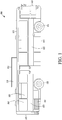
- FIG. 1 illustrates a side view of a transport vehicle 100 including a transport HVAC system 130, according to some embodiments.
- the illustrated transport vehicle 100 is a passenger bus.
- the transport vehicle 100 can be another type of passenger vehicle (e.g., a passenger railcar, etc.).
- the transport vehicle 100 includes a frame 105, an engine (not shown) (e.g., an internal combustion engine, etc.) disposed within an engine compartment 110, front wheels 115, and rear wheels 120.
- a passenger compartment 125 represents a conditioned space of the transport vehicle 100.
- the passenger compartment 125 can also be referred to as the cabin 125.
- the passenger compartment 125 can also be referred to as the conditioned space of the transport vehicle 100 and can be heated or cooled with the transport HVAC system 130.
- the passenger compartment 125 can be heated or cooled by opening one or more windows 160.
- the transport vehicle 100 can also include an optional air cleaning unit (not shown in FIG. 1 ).
- the passenger compartment 125 includes a front 140, a back 145, a right side 150, a left side (not shown in FIG. 1 ), and a roof 155.
- the right side 150 includes windows 160.
- the left side can be the same as or similar to the right side 150. In some embodiments, the left side can be different than the right side 150. For example, the left side may not include windows.
- the transport HVAC system 130 can include a fresh air intake (not shown in FIG. 1 ), a compressor (not shown in FIG. 1 ), a condenser (not shown in FIG. 1 ), an expansion valve (not shown in FIG. 1 ), an evaporator (not shown in FIG. 1 ), and a conditioned air discharge (not shown in FIG. 1 ).
- the components of the transport HVAC system 130 can be housed within a housing 165.
- the housing 165 can protect the components of the transport HVAC system 130 from environmental conditions (e.g., rain, snow, ultraviolet rays, etc.).
- the housing 165 can also function as an aesthetic feature that prevents people from seeing the individual components of the transport HVAC system 130.
- the transport HVAC system 130 can include additional components in some embodiments.
- the transport HVAC system 130 can include a dryer (not shown in FIG. 1 ), an economizer (not shown in FIG. 1 ), a prime mover (not shown in FIG. 1 ), and other components (e.g., a controller and a fresh air damper as shown in FIG. 2 ).
- the housing 165 can include additional components in some embodiments.
- the housing 165 can include a controller (not shown in FIG. 1 ), a power source (e.g., a battery, etc.) (not shown in FIG. 1 ), and other similar components.
- the optional air cleaning unit can include a filter media (not shown) for filtering contaminants (e.g., dust particles, etc.) out of the conditioned air being provided to the passenger compartment 125. Similar to the transport HVAC system 130, the optional air cleaning unit can include an air cleaner housing (not shown in FIG. 1 ).
- the air cleaner housing can function similar to the housing 165 of the transport HVAC system 130 and can, for example, be included for aesthetics or to protect the air cleaning unit from environmental conditions.
- FIG. 2 illustrates a block diagram of a side view of a transport vehicle 200 including a transport HVAC system 230 with a fresh air control system, according to some embodiments.
- the illustrated transport vehicle 200 is a passenger bus.
- the transport vehicle 200 can be another type of passenger vehicle (e.g., a passenger railcar, etc.). Aspects of FIG. 2 can be the same as or similar to aspects of FIG. 1 .
- the transport vehicle 200 includes a passenger compartment 225 that represents a conditioned space of the transport vehicle 200.
- the passenger compartment 225 can also be referred to as the cabin 225.
- the passenger compartment 225 can also be referred to as the conditioned space 225 of the transport vehicle 200.
- the passenger compartment 225 can be heated or cooled with a transport HVAC system 230.
- the transport vehicle 200 can also include an air cleaning unit (not shown in FIG. 2 ). The optional air cleaning unit can be incorporated into the transport HVAC system 230.
- the passenger compartment 225 includes a sensor 280.
- the sensor 280 can be configured to provide feedback to an HVAC controller 270 regarding one or more environmental conditions.
- the HVAC controller 270 and the sensor 280 are described in further detail below.
- the transport HVAC system 230 can include a fresh air intake (not shown in FIG. 2 ), a compressor (not shown in FIG. 2 ), a condenser (not shown in FIG. 2 ), an expansion valve (not shown in FIG. 2 ), an evaporator (not shown in FIG. 2 ), and a supply air outlet (not shown in FIG. 2 ).
- the components of the transport HVAC system 230 can be housed within the housing 265.
- the transport HVAC system 230 can include additional components in some embodiments.
- the transport HVAC system 230 can include a dryer (not shown in FIG. 2 ), an economizer (not shown in FIG. 2 ), a prime mover (not shown in FIG. 2 ), and other components (e.g., a fresh air damper 275, etc.).
- the evaporator (not shown in FIG. 2 ) can include an evaporator fan (not shown in FIG. 2 ).
- the evaporator fan can operate in a high speed mode or a low speed mode.
- the evaporator fan can operate in a low speed mode, a high speed mode, and at least one intermediate mode (e.g., a medium speed mode that is between high speed mode and low speed mode, etc.).
- the evaporator fan can be a variable speed evaporator fan that can operate at variable speeds between a high speed mode and a low speed mode.
- the transport HVAC system 230 can include variable speed evaporator fans without a fresh air damper.
- an evaporator fan at high speed may operate similarly to an evaporator fan with a constant speed and an open fresh air damper.
- An evaporator fan at low speed may operate similarly to an evaporator fan with a constant speed and a closed fresh air damper.
- the transport HVAC system 230 includes the HVAC controller 270 and a fresh air damper 275.
- the HVAC controller 270 and the fresh air damper 275 are in communication.
- the HVAC controller 270 can be configured to manage, command, direct, and regulate the behavior of one or more components of the transport HVAC system 230 (e.g., the fresh air damper 275, etc.).
- the HVAC controller 270 can control the transport HVAC system 230 to obtain various operating conditions (e.g., temperature, humidity, air quality, etc.) of the passenger compartment 225.
- the HVAC controller 270 can be powered by a primary mover (not shown) and/or another power source electrically connected to the HVAC controller 270 (e.g., a battery).
- the HVAC controller 270 can include a processor (not shown in FIG. 2 ), a memory (not shown in FIG. 2 ), a clock (not shown in FIG. 2 ), and an input/output (I/O) interface (not shown in FIG. 2 ), etc.
- the HVAC controller 270 can include fewer or additional components.
- the HVAC controller 270 can be configured to modify a position of the fresh air damper 275 to control an amount of fresh air input into the passenger compartment 225.
- the fresh air damper 275 can be configured to control an amount of fresh air input into the passenger compartment 225 of the transport vehicle 200.
- the fresh air damper 275 can have two positions (e.g., open or closed), according to some embodiments. In a closed position, the fresh air damper 275 can prevent fresh air from entering the transport vehicle 200. In an open position, the fresh air damper 275 can input fresh air into the transport vehicle 200.
- One or more operating conditions (e.g., evaporator fan speed, etc.) of the transport HVAC system 230 can be modified by the controller 270 in conjunction with opening or closing the fresh air damper 275.
- the fresh air damper 275 can have more than two positions.
- the fresh air damper 275 can have at least one intermediate position in which fresh air is input into the transport vehicle 200 in some amount that is less than the air input when the fresh air damper 275 is in the fully opened position.
- the sensor 280 is located within the passenger compartment 225 and is configured to provide feedback on one or more environmental conditions of the passenger compartment 225 to the HVAC controller 270.
- the sensor 280 can be located within a duct (not shown) of the transport HVAC system 230.
- the sensor 280 can be located in a return air duct (not shown) in the transport HVAC system 230.
- the sensor 280 can include a variety of sensors configured to detect air quality.
- the sensor 280 can be a carbon dioxide sensor, a relative humidity sensor, a dust sensor, a volatile organic compound sensor (VOC), or other suitable air quality sensor.
- the sensor 280 can be a combination of two or more types of air quality sensors.
- the sensor 280 can include a temperature sensor in some embodiments.
- the optional air cleaning unit can include a filter media for filtering contaminants (e.g., dust particles, etc.) out of the conditioned air being provided to the passenger compartment 225 (e.g., the supply air). Similar to the transport HVAC system 230, the air cleaning unit can include an air cleaner housing (not shown in FIG. 2 ) that is separate from the transport HVAC system 230.
- the air cleaner housing may function similar to the housing 265 and can, for example, be included for aesthetics or to protect the air cleaning unit.
- the optional air cleaning unit can be contained within the housing 265 of the transport HVAC system 230.
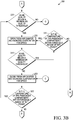
- FIGS. 3A and 3B illustrate a flowchart of a method 300 to control a transport HVAC system (e.g., the transport HVAC system 230 shown in FIG. 2 ), according to some embodiments.
- the method 300 generally controls a supply of fresh air into a passenger compartment (e.g., the passenger compartment 225 shown in FIG. 2 ) of a transport vehicle (e.g., a passenger bus such as in FIGS. 1 or 2 , a passenger railcar, etc.). By controlling the supply of fresh air, the method 300 can maintain air quality within the passenger compartment.
- the method 300 begins at 305 when the transport HVAC system is started (e.g., powered on). In some embodiments, the method 300 repeats while the transport HVAC system is powered on.
- the controller determines whether a temperature of the passenger compartment is within a threshold range of a set point temperature of the passenger compartment.
- the threshold range can, for example, be based on a thermostat of the transport HVAC system. In some embodiments, the range, for example, can be plus or minus about two degrees from the set point temperature. However, it will be appreciated that the range may be modified based on a particular application or user preference. If the temperature of the passenger compartment is not within the threshold range, then the method 300 continues to 315. If the temperature is within the threshold range, then the method 300 continues to 320.
- the controller determines whether free heating or cooling is available.
- Free cooling is considered available when the ambient temperature is lower than the set point temperature.
- free cooling is available when the ambient temperature is within the range from about the set point temperature to about two degrees less than the set point temperature.
- Free heating is available when the ambient temperature is greater than the set point temperature.
- free heating is available when the ambient temperature is within the range from about the set point temperature to about two degrees greater than the set point temperature.
- the range above or below the set point temperature in which free heating or free cooling (respectively) is available can be a range other than about two degrees. The range can vary and be modified based on a particular application or user preference.
- the HVAC system can open the fresh air damper and disable either heating or cooling, providing air at the ambient temperature.
- the windows or doors may be opened to provide free heating or cooling.
- less energy e.g., fuel, etc.
- free heating/cooling mode includes opening a fresh air damper (e.g., the fresh air damper 275 shown in FIG. 2 ) and turning the evaporator fan to a high speed mode regardless of whether an air quality measurement is below a minimum air quality limit. Further, the fresh air damper can be opened and the evaporator fan can be operated in a high speed mode without having to consider the vehicle occupancy. Accordingly, a surplus of fresh air can be added to the passenger compartment.
- a fresh air damper e.g., the fresh air damper 275 shown in FIG. 2
- the fresh air damper can be opened and the evaporator fan can be operated in a high speed mode without having to consider the vehicle occupancy. Accordingly, a surplus of fresh air can be added to the passenger compartment.
- opening the fresh air damper includes fully opening the fresh air damper. In some embodiments, opening the fresh air damper includes opening the fresh air damper to an intermediate position. When the fresh air damper is open and the evaporator fan is in the high speed mode, fresh air is introduced into the passenger compartment of the transport vehicle.
- the free heating or cooling mode can continue until the set point temperature is reached. In other embodiments, free heating can continue until the set point temperature is reached or until the ambient temperature is lower than the temperature of the passenger compartment and free cooling can continue until the set point temperature is reached or until the ambient temperature is greater than the temperature of the passenger compartment.
- the method 300 When free heating or cooling is not available or the set point temperature is reached, then the method 300 continues to 325 and operates in standard mode.
- the standard mode can also be referred to as temperature control mode.
- the transport HVAC system runs the evaporator fan in the high-speed mode when the temperature of the passenger compartment is outside the threshold range of the set point temperature and in the low speed mode when the temperature of the passenger compartment is within the threshold range of the set point temperature. That is, in the standard mode, temperature control takes precedence over demand controlled ventilation.
- the fresh air damper may be closed to prevent introduction of ambient air at an undesired temperature (e.g., warmer ambient air if cooling or cooler ambient air if heating).
- the method 300 continues to 320.
- the controller determines whether an air quality measurement in the passenger compartment is below a minimum air quality threshold.
- the air quality measurement can be a reading from a sensor (e.g., the sensor 280 shown in FIG. 2 ).
- the sensor can be a carbon dioxide sensor, a volatile organic compound sensor (VOC), or other similar type of sensor. If the air quality measurement is below a minimum air quality threshold, even though the temperature of the passenger compartment is within the threshold range of the set point temperature, the controller will open the damper and increase the evaporator fan speed at 335 so that the transport HVAC system is operating at an increased efficiency.
- the method 300 continues to 350, which will be discussed in additional detail below.
- the value of the minimum air quality threshold may depend on the type of sensor and therefore, the parameter of the air being measured. For example, a minimum air quality threshold for carbon dioxide may be different than a minimum air quality threshold for a VOC.
- the minimum air quality threshold can be set based on air quality standards or simulation testing to identify a comfortable air quality operating region.
- the method 300 continues to 340.
- the controller again takes an air quality measurement from the passenger compartment of the transport vehicle. If the air quality measurement is below the air quality threshold, the controller will determine whether the temperature of the passenger compartment is within the threshold range of the set point temperature at 345. If the air quality measurement is not below the air quality threshold, the method 300 continues to 350.
- the method 300 continues to 335. If, however, the temperature of the passenger compartment is not within the threshold range of the set point temperature, the method 300 continues to 315.
- the controller closes the fresh air damper and decreases the evaporator fan speed.
- the method 300 continues to 355 and determines whether the temperature of the passenger compartment is within the threshold range of the set point temperature. If the temperature is within the threshold range, then the method 300 continues to 320. If, however, the temperature is not within the threshold range, then the method continues to 315.
Claims (9)
- Verfahren zum Steuern eines Transportheizungs-, - lüftungs- und Klimatisierungs(HLK)-Systems (230) mit einem Frischlufteinlass, das Folgendes umfasst:
Überwachen einer Luftqualität, einer Einstellpunkttemperatur und einer Fahrgastraumtemperatur innerhalb eines Fahrgastraums (125, 225), und Überwachen einer Umgebungstemperatur, dadurch gekennzeichnet, dass das Verfahren ferner Folgendes umfasst:
Bestimmen, ob die Fahrgastraumtemperatur innerhalb eines Schwellbereichs der Einstellpunkttemperatur ist, und wenn die Fahrgastraumtemperatur innerhalb des Schwellbereichs der Einstellpunkttemperatur ist:Bestimmen, ob eine Frischluftbedingung erfüllt ist, basierend auf der Überwachung;Öffnen einer Frischluftklappe (275), wenn die Frischluftbedingung erfüllt ist; undErhöhen einer Verdampfergebläsedrehzahl in Reaktion auf Öffnen der Frischluftklappe (275),wobei die Frischluftbedingung eine Mindestluftqualitätsschwelle umfasst, wobei die Frischluftbedingung erfüllt ist, wenn die Überwachung eine Luftqualität identifiziert, die unter der Mindestluftqualitätsschwelle ist, undwenn die Fahrgastraumtemperatur nicht innerhalb des Schwellbereichs der Einstellpunkttemperatur liegt, Bestimmen, ob die Umgebungstemperatur entweder innerhalb eines Umgebungstemperaturschwellbereichs über der Einstellpunkttemperatur oder innerhalb des Umgebungstemperaturschwellbereichs unter der Einstellpunkttemperatur ist, und wenn die Umgebungstemperatur entweder innerhalb des Umgebungstemperaturschwellbereichs über der Einstellpunkttemperatur oder innerhalb des Umgebungstemperaturschwellbereichs unter der Einstellpunkttemperatur ist:
Öffnen der Frischluftklappe (275) und Erhöhen der Verdampfergebläsedrehzahl in Reaktion auf Öffnen der Frischluftklappe. - Verfahren nach Anspruch 1, wobei Öffnen der Frischluftklappe (275) Öffnen der Frischluftklappe (275) auf eine Zwischenposition umfasst, wobei die Zwischenposition zwischen einer geöffneten Position und einer geschlossenen Position ist.
- Verfahren nach Anspruch 1, wobei Erhöhen der Verdampfergebläsedrehzahl Erhöhen der Verdampfergebläsedrehzahl auf eine Zwischenverdampfergebläsedrehzahl umfasst, die unter einer maximalen Verdampfergebläsedrehzahl ist.
- Verfahren nach Anspruch 1, ferner umfassend:Schließen der Frischluftklappe (275), wenn die Frischluftbedingung nicht länger erfüllt ist; undVerringern der Verdampfergebläsedrehzahl in Reaktion auf Schließen der Frischluftklappe (275).
- Verfahren nach Anspruch 4, wobei Schließen der Frischluftklappe (275) Schließen der Frischluftklappe (275) auf eine Zwischenposition umfasst, wobei die Zwischenposition zwischen einer geschlossenen Position und einer geöffneten Position ist.
- Verfahren nach Anspruch 4, wobei Verringern der Verdampfergebläsedrehzahl Verringern der Verdampfergebläsedrehzahl auf eine Zwischenverdampfergebläsedrehzahl umfasst, die über einer minimalen Verdampfergebläsedrehzahl ist.
- Frischlufteinlasssystem für ein Transportheizungs-, -lüftungs- und Klimatisierungs(HLK)-System (230), das Folgendes umfasst:eine Frischluftklappe (275), ausgelegt zum Regeln einer Strömung von Frischluft in das Transport-HLK-System (230) ;ein Verdampfergebläse mit zumindest einem Modus mit hoher Drehzahl und einem Modus mit niedriger Drehzahl;einen Temperatursensor (280); undeine Steuerung (270), ausgelegt zum Durchführen des Verfahrens nach Anspruch 1.
- Frischlufteinlasssystem nach Anspruch 7, wobei der eine oder die mehreren Qualitätssensoren (280) einen Kohlendioxidsensor umfassen, ausgelegt zum Detektieren einer Menge von Kohlendioxid in einem Fahrgastraum (225) eines Transportfahrzeugs (200).
- Frischlufteinlasssystem nach Anspruch 7, wobei die Steuerung (230) ferner ausgelegt ist zum:Verringern der Frischluftströmung in Reaktion auf Bestimmen, dass die Frischluftbedingung nicht länger erfüllt ist; undVerringern der Verdampfergebläsedrehzahl, wenn die Frischluftströmung verringert wird.
Applications Claiming Priority (2)
| Application Number | Priority Date | Filing Date | Title |
|---|---|---|---|
| US201361908463P | 2013-11-25 | 2013-11-25 | |
| PCT/US2014/040706 WO2015076872A1 (en) | 2013-11-25 | 2014-06-03 | Fresh air control for a transport refrigeration unit |
Publications (3)
| Publication Number | Publication Date |
|---|---|
| EP3074252A1 EP3074252A1 (de) | 2016-10-05 |
| EP3074252A4 EP3074252A4 (de) | 2017-09-20 |
| EP3074252B1 true EP3074252B1 (de) | 2020-02-12 |
Family
ID=53179983
Family Applications (1)
| Application Number | Title | Priority Date | Filing Date |
|---|---|---|---|
| EP14863536.0A Active EP3074252B1 (de) | 2013-11-25 | 2014-06-03 | Frischluftkontrolle für eine transportkühleinheit |
Country Status (4)
| Country | Link |
|---|---|
| US (1) | US9908386B2 (de) |
| EP (1) | EP3074252B1 (de) |
| CN (1) | CN105873779B (de) |
| WO (1) | WO2015076872A1 (de) |
Cited By (1)
| Publication number | Priority date | Publication date | Assignee | Title |
|---|---|---|---|---|
| EP3640112B1 (de) | 2017-06-12 | 2021-11-17 | Mitsubishi Electric Corporation | Fahrzeugklimatisierungsvorrichtung und klimatisierungsverfahren einer fahrzeugklimatisierungsvorrichtung |
Families Citing this family (26)
| Publication number | Priority date | Publication date | Assignee | Title |
|---|---|---|---|---|
| EP2969613B1 (de) | 2013-03-13 | 2018-08-08 | Bergstrom, Inc. | Klimaanlage mit wärmerückgewinnungslüftung für frischluftzufuhr und temperatursteuerung |
| WO2015065495A1 (en) | 2013-11-04 | 2015-05-07 | Bergstrom, Inc. | Low profile air conditioning system |
| WO2015079895A1 (ja) * | 2013-11-28 | 2015-06-04 | 三菱電機株式会社 | 車両用空気調和装置及びこれを備えた鉄道車両 |
| US9783024B2 (en) | 2015-03-09 | 2017-10-10 | Bergstrom Inc. | System and method for remotely managing climate control systems of a fleet of vehicles |
| WO2017096390A1 (en) * | 2015-12-03 | 2017-06-08 | Soifer Scott Andrew | Vehicular heatstroke prevention device |
| US9874384B2 (en) | 2016-01-13 | 2018-01-23 | Bergstrom, Inc. | Refrigeration system with superheating, sub-cooling and refrigerant charge level control |
| US10589598B2 (en) | 2016-03-09 | 2020-03-17 | Bergstrom, Inc. | Integrated condenser and compressor system |
| FR3051725B1 (fr) * | 2016-05-26 | 2020-04-17 | Valeo Systemes Thermiques | Systeme de qualite d'air pour vehicule automobile |
| US10081226B2 (en) | 2016-08-22 | 2018-09-25 | Bergstrom Inc. | Parallel compressors climate system |
| US10562372B2 (en) | 2016-09-02 | 2020-02-18 | Bergstrom, Inc. | Systems and methods for starting-up a vehicular air-conditioning system |
| US10675948B2 (en) | 2016-09-29 | 2020-06-09 | Bergstrom, Inc. | Systems and methods for controlling a vehicle HVAC system |
| US10724772B2 (en) | 2016-09-30 | 2020-07-28 | Bergstrom, Inc. | Refrigerant liquid-gas separator having an integrated check valve |
| US10369863B2 (en) | 2016-09-30 | 2019-08-06 | Bergstrom, Inc. | Refrigerant liquid-gas separator with electronics cooling |
| US10525791B2 (en) | 2017-03-28 | 2020-01-07 | International Business Machines Corporation | Intelligent in-vehicle air-quality control |
| US10281179B1 (en) * | 2017-04-07 | 2019-05-07 | David John Prezioso | Replacement compressor assembly for an air conditioning system and method |
| US10399409B2 (en) * | 2017-05-16 | 2019-09-03 | GM Global Technology Operations LLC | System and method for reducing volatile organic compounds within a vehicle |
| US11448441B2 (en) | 2017-07-27 | 2022-09-20 | Bergstrom, Inc. | Refrigerant system for cooling electronics |
| US11648818B2 (en) * | 2017-10-27 | 2023-05-16 | Mitsubishi Electric Corporation | Air-conditioning system |
| DE102018124748B4 (de) * | 2017-11-24 | 2023-02-09 | Hanon Systems | Mehrzonenklimaanlage für Fahrzeuge |
| US11420496B2 (en) | 2018-04-02 | 2022-08-23 | Bergstrom, Inc. | Integrated vehicular system for conditioning air and heating water |
| CN109028290A (zh) * | 2018-04-20 | 2018-12-18 | 青岛海尔空调器有限总公司 | 一种空调室内机及其换新风的控制方法 |
| CN108731198A (zh) * | 2018-04-20 | 2018-11-02 | 青岛海尔空调器有限总公司 | 一种空调室内机及其换新风的控制方法 |
| US11105549B2 (en) * | 2018-10-15 | 2021-08-31 | Haier Us Appliance Solutions, Inc. | Refrigerator appliance with a convertible compartment |
| KR20210022916A (ko) * | 2019-08-21 | 2021-03-04 | 현대자동차주식회사 | 차량용 공조 시스템 제어방법 |
| EP3808658A1 (de) | 2019-10-14 | 2021-04-21 | Hamilton Sundstrand Corporation | Klimasteuerungsanlage |
| CN114132145B (zh) * | 2021-12-09 | 2022-08-12 | 三河科达实业有限公司 | 一种带节能温控功能的野战防疫车 |
Family Cites Families (53)
| Publication number | Priority date | Publication date | Assignee | Title |
|---|---|---|---|---|
| US3733849A (en) | 1971-06-29 | 1973-05-22 | Sun Shipbuilding & Dry Dock Co | Apparatus for transportation of commodities |
| US3862549A (en) * | 1972-11-29 | 1975-01-28 | United Aircraft Prod | Modular environmental control system |
| US3896634A (en) | 1974-02-19 | 1975-07-29 | Coleman Co | Air conditioning system |
| JPS5617714A (en) * | 1979-07-24 | 1981-02-19 | Nippon Denso Co Ltd | Internal/external air intake control method and apparatus |
| US4646964A (en) * | 1982-03-26 | 1987-03-03 | Parker Electronics, Inc. | Temperature control system |
| JPH04163269A (ja) * | 1990-10-25 | 1992-06-08 | Toshiba Corp | 車両用空気調和装置の制御装置 |
| US5275012A (en) * | 1993-01-07 | 1994-01-04 | Ford Motor Company | Climate control system for electric vehicle |
| US5971067A (en) * | 1996-02-15 | 1999-10-26 | Carrier Corporation | Air quality control system |
| DE19715748C1 (de) * | 1997-04-16 | 1998-05-07 | Mc Micro Compact Car Ag | Fahrzeugklimatisierungsüberwachungsvorrichtung |
| US5976010A (en) * | 1997-06-27 | 1999-11-02 | York International Corporation | Energy efficient air quality maintenance system and method |
| DE19847504C1 (de) * | 1998-10-15 | 2000-11-16 | Deutsche Bahn Ag | Verfahren zur Steuerung der Luftvolumenströme in einer raumlufttechnischen Anlage |
| JP2000219036A (ja) * | 1999-01-29 | 2000-08-08 | Shukuji Asakura | 自動車用自動換気装置 |
| DE19962966C1 (de) | 1999-12-24 | 2001-06-07 | Bosch Gmbh Robert | Vorrichtung zum Belüften eines Kraftfahrzeugs |
| US6415617B1 (en) * | 2001-01-10 | 2002-07-09 | Johnson Controls Technology Company | Model based economizer control of an air handling unit |
| DE10128166A1 (de) | 2001-06-09 | 2002-12-12 | Behr Gmbh & Co | Verfahren zur Einstellung eines Umluftanteils der einer Fahrgastzelle zugeführten Zuluft |
| DE10132377A1 (de) | 2001-07-06 | 2003-01-30 | Daimler Chrysler Ag | Verfahren zur Regelung einer Klimatisierungseinrichtung mit einer Frischluft und einer Umluftzufuhr |
| US6494777B1 (en) | 2001-09-19 | 2002-12-17 | King Can Industry Corporation | Carbon dioxide concentration modulating device |
| US6581544B1 (en) | 2001-10-24 | 2003-06-24 | Smithway, Inc. | Air conditioned trailer for transporting living fowl |
| DE10154387A1 (de) * | 2001-11-06 | 2003-05-15 | Opel Adam Ag | Lüftungsanlage für einen Innenraum eines Kraftfahrzeuges |
| DE10161254A1 (de) * | 2001-12-13 | 2003-07-03 | Konvekta Ag | Klimatisierungseinrichtung für ein Fahrzeug |
| US6923111B2 (en) | 2002-02-27 | 2005-08-02 | Carrier Corporation | Mobile container for perishable goods |
| JP4110906B2 (ja) * | 2002-02-28 | 2008-07-02 | 株式会社デンソー | 車両用空調装置 |
| DE10237834A1 (de) | 2002-08-19 | 2004-03-04 | Robert Bosch Gmbh | Sicherheitssystem für eine Einrichtung zur Energieerzeugung |
| US20040046038A1 (en) * | 2002-09-09 | 2004-03-11 | Knowles Thomas C. | Blending air apparatus |
| US6758739B1 (en) | 2003-03-04 | 2004-07-06 | Delphi Technologies, Inc. | Air quality system for a vehicle |
| US6877330B2 (en) * | 2003-05-05 | 2005-04-12 | Carrier Corporation | Integrated air conditioning module for a bus |
| US6763670B1 (en) * | 2003-05-05 | 2004-07-20 | Carrier Corporation | Configuration for modular rooftop air conditioning system |
| US6763669B1 (en) * | 2003-05-05 | 2004-07-20 | Carrier Corporation | Modular air conditioner for a bus rooftop |
| US6983619B2 (en) * | 2003-05-05 | 2006-01-10 | Carrier Corporation | Bus rooftop condenser fan |
| US7051544B2 (en) * | 2003-05-05 | 2006-05-30 | Carrier Corporation | Modular bus air conditioning system |
| US6718784B1 (en) * | 2003-05-05 | 2004-04-13 | Carrier Corporation | Evaporator air system for rooftop bus air conditioner |
| DE102004024284A1 (de) * | 2003-07-17 | 2005-02-03 | Robert Bosch Gmbh | Verfahren und Vorrichtung zur Durchführung von Gefahrabwendungsmassnahmen für Lebewesen in Kraftfahrzeugen |
| MXPA05005842A (es) * | 2003-10-02 | 2005-08-26 | Thermo King Deutschland Gmbh | Sistema de aire acondicionado para montaje en techo para vehiculos, en particular autobuses. |
| US7434413B2 (en) * | 2005-01-10 | 2008-10-14 | Honeywell International Inc. | Indoor air quality and economizer control methods and controllers |
| US7472554B2 (en) * | 2005-02-14 | 2009-01-06 | Continental Teves, Inc. | Passenger environmental protection |
| US20070056299A1 (en) * | 2005-09-15 | 2007-03-15 | Shankweiler Matthew C | Modified thermostatic control for enhanced air quality |
| US7758407B2 (en) * | 2006-09-26 | 2010-07-20 | Siemens Industry, Inc. | Ventilation control based on occupancy |
| US7827813B2 (en) * | 2007-01-30 | 2010-11-09 | Johnson Controls Technology Company | Adaptive real-time optimization control |
| US20080179408A1 (en) * | 2007-01-30 | 2008-07-31 | Johnson Controls Technology Company | Sensor-free optimal control of air-side economizer |
| US8641490B2 (en) | 2007-04-09 | 2014-02-04 | Nissan North America, Inc. | Vehicle air recirculation control device |
| CN101497300A (zh) | 2008-01-30 | 2009-08-05 | 鸿富锦精密工业(深圳)有限公司 | 汽车及其空调系统和汽车空调系统控制方法与控制装置 |
| KR20090094978A (ko) * | 2008-03-04 | 2009-09-09 | 한라공조주식회사 | 차량용 공조시스템의 제어장치 |
| US8313038B2 (en) * | 2008-06-25 | 2012-11-20 | Minebea Co., Ltd. | Telecom shelter cooling and control system |
| CN101737910A (zh) * | 2008-11-07 | 2010-06-16 | 塞莫金公司 | 新鲜空气箱 |
| US8506367B2 (en) | 2009-07-30 | 2013-08-13 | Thermo King Corporation | Mobile air cleaning unit and distribution system |
| US8145383B2 (en) | 2009-08-18 | 2012-03-27 | Toyota Motor Engineering & Manufacturing North America, Inc. | Process and system for controlling air quality within an interior of a motor vehicle |
| US8918218B2 (en) * | 2010-04-21 | 2014-12-23 | Honeywell International Inc. | Demand control ventilation system with remote monitoring |
| US20120015594A1 (en) * | 2010-07-14 | 2012-01-19 | Thermo King Corporation | Demand-based fresh air control system |
| US9044101B2 (en) * | 2012-03-29 | 2015-06-02 | Mario Garcia Garcia | Climate controlled sleeping space |
| US8649941B1 (en) | 2012-08-14 | 2014-02-11 | Nissan North America, Inc. | Method for operating a vehicle system |
| US9709294B2 (en) * | 2012-09-20 | 2017-07-18 | Consolidated Energy Solutions Inc. | Air conditioning system for dehumidifying and cooling air |
| JP2016521655A (ja) * | 2013-07-24 | 2016-07-25 | インテル コーポレイション | 車両区画のための適応室内空気質制御装置及び方法 |
| US9254459B2 (en) * | 2013-09-17 | 2016-02-09 | Gregory R. Miller | Room air purifier with pressurization relief |
-
2014
- 2014-06-03 CN CN201480072226.0A patent/CN105873779B/zh active Active
- 2014-06-03 WO PCT/US2014/040706 patent/WO2015076872A1/en active Application Filing
- 2014-06-03 US US15/039,212 patent/US9908386B2/en active Active
- 2014-06-03 EP EP14863536.0A patent/EP3074252B1/de active Active
Non-Patent Citations (1)
| Title |
|---|
| None * |
Cited By (1)
| Publication number | Priority date | Publication date | Assignee | Title |
|---|---|---|---|---|
| EP3640112B1 (de) | 2017-06-12 | 2021-11-17 | Mitsubishi Electric Corporation | Fahrzeugklimatisierungsvorrichtung und klimatisierungsverfahren einer fahrzeugklimatisierungsvorrichtung |
Also Published As
| Publication number | Publication date |
|---|---|
| EP3074252A1 (de) | 2016-10-05 |
| US20170136848A1 (en) | 2017-05-18 |
| CN105873779B (zh) | 2019-05-31 |
| US9908386B2 (en) | 2018-03-06 |
| EP3074252A4 (de) | 2017-09-20 |
| CN105873779A (zh) | 2016-08-17 |
| WO2015076872A1 (en) | 2015-05-28 |
Similar Documents
| Publication | Publication Date | Title |
|---|---|---|
| EP3074252B1 (de) | Frischluftkontrolle für eine transportkühleinheit | |
| JP4897692B2 (ja) | 車両における再循環空気と新鮮な空気との混合物を制御する装置及び方法 | |
| RU2569974C2 (ru) | Устройство и способ селективного контроля впуска воздуха для системы кондиционирования воздуха | |
| US9758015B2 (en) | Vehicle comfort system with efficient coordination of complementary thermal units | |
| US7975496B2 (en) | Vehicle air conditioning system | |
| CN108068577B (zh) | 一种热泵空调系统、电动汽车及其控制方法 | |
| US9493054B2 (en) | Vehicle HVAC control system | |
| US8302417B2 (en) | Air conditioning system with cold thermal storage and evaporator temperature control | |
| US7275379B2 (en) | Automotive HVAC system and method of operating same utilizing enthalpy-based control | |
| CN105020921A (zh) | 车辆用空气调节装置 | |
| US20160236537A1 (en) | System and method of controlling ventilation of a passenger compartment of a vehicle | |
| KR20130030264A (ko) | 차량 공기 조화 시스템 | |
| US11267317B2 (en) | System for controlling inside/outside air in air conditioner | |
| JP4928923B2 (ja) | 車両用空調装置 | |
| KR101250274B1 (ko) | 축냉기를 구비한 차량용 공조장치의 제어방법 | |
| KR101418849B1 (ko) | 차량용 공조장치 및 그 제어방법 | |
| KR101587658B1 (ko) | 차량의 공조장치 및 그 제어방법 | |
| KR20100022693A (ko) | 차량용 공조장치의 제어방법 | |
| JP3336886B2 (ja) | 車両用空調装置 | |
| KR100569983B1 (ko) | Fatc-hvac 시스템의 인테이크 도어 가변제어방법 | |
| KR20180026276A (ko) | 선박 에어컨 에너지 절감방법 | |
| CN117445616A (zh) | 车辆及其热管理方法和装置、计算机可读存储介质 | |
| CN116353290A (zh) | 一种基于座舱热舒适性的暖通空调系统及其控制方法 | |
| KR20140114579A (ko) | 차량 공조 장치의 자동 제어 시스템 및 그 제어 방법 | |
| KR20140111444A (ko) | 전기자동차용 공조장치 |
Legal Events
| Date | Code | Title | Description |
|---|---|---|---|
| PUAI | Public reference made under article 153(3) epc to a published international application that has entered the european phase |
Free format text: ORIGINAL CODE: 0009012 |
|
| 17P | Request for examination filed |
Effective date: 20160624 |
|
| AK | Designated contracting states |
Kind code of ref document: A1 Designated state(s): AL AT BE BG CH CY CZ DE DK EE ES FI FR GB GR HR HU IE IS IT LI LT LU LV MC MK MT NL NO PL PT RO RS SE SI SK SM TR |
|
| AX | Request for extension of the european patent |
Extension state: BA ME |
|
| DAX | Request for extension of the european patent (deleted) | ||
| A4 | Supplementary search report drawn up and despatched |
Effective date: 20170823 |
|
| RIC1 | Information provided on ipc code assigned before grant |
Ipc: B60H 1/00 20060101AFI20170811BHEP Ipc: B60H 1/24 20060101ALI20170811BHEP |
|
| STAA | Information on the status of an ep patent application or granted ep patent |
Free format text: STATUS: EXAMINATION IS IN PROGRESS |
|
| 17Q | First examination report despatched |
Effective date: 20180712 |
|
| GRAP | Despatch of communication of intention to grant a patent |
Free format text: ORIGINAL CODE: EPIDOSNIGR1 |
|
| STAA | Information on the status of an ep patent application or granted ep patent |
Free format text: STATUS: GRANT OF PATENT IS INTENDED |
|
| INTG | Intention to grant announced |
Effective date: 20190828 |
|
| GRAS | Grant fee paid |
Free format text: ORIGINAL CODE: EPIDOSNIGR3 |
|
| GRAA | (expected) grant |
Free format text: ORIGINAL CODE: 0009210 |
|
| STAA | Information on the status of an ep patent application or granted ep patent |
Free format text: STATUS: THE PATENT HAS BEEN GRANTED |
|
| AK | Designated contracting states |
Kind code of ref document: B1 Designated state(s): AL AT BE BG CH CY CZ DE DK EE ES FI FR GB GR HR HU IE IS IT LI LT LU LV MC MK MT NL NO PL PT RO RS SE SI SK SM TR |
|
| REG | Reference to a national code |
Ref country code: GB Ref legal event code: FG4D |
|
| REG | Reference to a national code |
Ref country code: CH Ref legal event code: EP |
|
| REG | Reference to a national code |
Ref country code: AT Ref legal event code: REF Ref document number: 1231627 Country of ref document: AT Kind code of ref document: T Effective date: 20200215 |
|
| REG | Reference to a national code |
Ref country code: DE Ref legal event code: R096 Ref document number: 602014061045 Country of ref document: DE |
|
| REG | Reference to a national code |
Ref country code: IE Ref legal event code: FG4D |
|
| PG25 | Lapsed in a contracting state [announced via postgrant information from national office to epo] |
Ref country code: FI Free format text: LAPSE BECAUSE OF FAILURE TO SUBMIT A TRANSLATION OF THE DESCRIPTION OR TO PAY THE FEE WITHIN THE PRESCRIBED TIME-LIMIT Effective date: 20200212 Ref country code: RS Free format text: LAPSE BECAUSE OF FAILURE TO SUBMIT A TRANSLATION OF THE DESCRIPTION OR TO PAY THE FEE WITHIN THE PRESCRIBED TIME-LIMIT Effective date: 20200212 Ref country code: NO Free format text: LAPSE BECAUSE OF FAILURE TO SUBMIT A TRANSLATION OF THE DESCRIPTION OR TO PAY THE FEE WITHIN THE PRESCRIBED TIME-LIMIT Effective date: 20200512 |
|
| REG | Reference to a national code |
Ref country code: LT Ref legal event code: MG4D |
|
| REG | Reference to a national code |
Ref country code: NL Ref legal event code: MP Effective date: 20200212 |
|
| PG25 | Lapsed in a contracting state [announced via postgrant information from national office to epo] |
Ref country code: BG Free format text: LAPSE BECAUSE OF FAILURE TO SUBMIT A TRANSLATION OF THE DESCRIPTION OR TO PAY THE FEE WITHIN THE PRESCRIBED TIME-LIMIT Effective date: 20200512 Ref country code: IS Free format text: LAPSE BECAUSE OF FAILURE TO SUBMIT A TRANSLATION OF THE DESCRIPTION OR TO PAY THE FEE WITHIN THE PRESCRIBED TIME-LIMIT Effective date: 20200612 Ref country code: LV Free format text: LAPSE BECAUSE OF FAILURE TO SUBMIT A TRANSLATION OF THE DESCRIPTION OR TO PAY THE FEE WITHIN THE PRESCRIBED TIME-LIMIT Effective date: 20200212 Ref country code: SE Free format text: LAPSE BECAUSE OF FAILURE TO SUBMIT A TRANSLATION OF THE DESCRIPTION OR TO PAY THE FEE WITHIN THE PRESCRIBED TIME-LIMIT Effective date: 20200212 Ref country code: GR Free format text: LAPSE BECAUSE OF FAILURE TO SUBMIT A TRANSLATION OF THE DESCRIPTION OR TO PAY THE FEE WITHIN THE PRESCRIBED TIME-LIMIT Effective date: 20200513 Ref country code: HR Free format text: LAPSE BECAUSE OF FAILURE TO SUBMIT A TRANSLATION OF THE DESCRIPTION OR TO PAY THE FEE WITHIN THE PRESCRIBED TIME-LIMIT Effective date: 20200212 |
|
| PG25 | Lapsed in a contracting state [announced via postgrant information from national office to epo] |
Ref country code: NL Free format text: LAPSE BECAUSE OF FAILURE TO SUBMIT A TRANSLATION OF THE DESCRIPTION OR TO PAY THE FEE WITHIN THE PRESCRIBED TIME-LIMIT Effective date: 20200212 |
|
| PG25 | Lapsed in a contracting state [announced via postgrant information from national office to epo] |
Ref country code: EE Free format text: LAPSE BECAUSE OF FAILURE TO SUBMIT A TRANSLATION OF THE DESCRIPTION OR TO PAY THE FEE WITHIN THE PRESCRIBED TIME-LIMIT Effective date: 20200212 Ref country code: SM Free format text: LAPSE BECAUSE OF FAILURE TO SUBMIT A TRANSLATION OF THE DESCRIPTION OR TO PAY THE FEE WITHIN THE PRESCRIBED TIME-LIMIT Effective date: 20200212 Ref country code: DK Free format text: LAPSE BECAUSE OF FAILURE TO SUBMIT A TRANSLATION OF THE DESCRIPTION OR TO PAY THE FEE WITHIN THE PRESCRIBED TIME-LIMIT Effective date: 20200212 Ref country code: SK Free format text: LAPSE BECAUSE OF FAILURE TO SUBMIT A TRANSLATION OF THE DESCRIPTION OR TO PAY THE FEE WITHIN THE PRESCRIBED TIME-LIMIT Effective date: 20200212 Ref country code: RO Free format text: LAPSE BECAUSE OF FAILURE TO SUBMIT A TRANSLATION OF THE DESCRIPTION OR TO PAY THE FEE WITHIN THE PRESCRIBED TIME-LIMIT Effective date: 20200212 Ref country code: LT Free format text: LAPSE BECAUSE OF FAILURE TO SUBMIT A TRANSLATION OF THE DESCRIPTION OR TO PAY THE FEE WITHIN THE PRESCRIBED TIME-LIMIT Effective date: 20200212 Ref country code: CZ Free format text: LAPSE BECAUSE OF FAILURE TO SUBMIT A TRANSLATION OF THE DESCRIPTION OR TO PAY THE FEE WITHIN THE PRESCRIBED TIME-LIMIT Effective date: 20200212 Ref country code: ES Free format text: LAPSE BECAUSE OF FAILURE TO SUBMIT A TRANSLATION OF THE DESCRIPTION OR TO PAY THE FEE WITHIN THE PRESCRIBED TIME-LIMIT Effective date: 20200212 Ref country code: PT Free format text: LAPSE BECAUSE OF FAILURE TO SUBMIT A TRANSLATION OF THE DESCRIPTION OR TO PAY THE FEE WITHIN THE PRESCRIBED TIME-LIMIT Effective date: 20200705 |
|
| REG | Reference to a national code |
Ref country code: DE Ref legal event code: R097 Ref document number: 602014061045 Country of ref document: DE |
|
| REG | Reference to a national code |
Ref country code: AT Ref legal event code: MK05 Ref document number: 1231627 Country of ref document: AT Kind code of ref document: T Effective date: 20200212 |
|
| PLBE | No opposition filed within time limit |
Free format text: ORIGINAL CODE: 0009261 |
|
| STAA | Information on the status of an ep patent application or granted ep patent |
Free format text: STATUS: NO OPPOSITION FILED WITHIN TIME LIMIT |
|
| REG | Reference to a national code |
Ref country code: DE Ref legal event code: R082 Ref document number: 602014061045 Country of ref document: DE Representative=s name: HL KEMPNER PATENTANWAELTE, SOLICITORS (ENGLAND, DE Ref country code: DE Ref legal event code: R082 Ref document number: 602014061045 Country of ref document: DE Representative=s name: HL KEMPNER PATENTANWALT, RECHTSANWALT, SOLICIT, DE |
|
| 26N | No opposition filed |
Effective date: 20201113 |
|
| PG25 | Lapsed in a contracting state [announced via postgrant information from national office to epo] |
Ref country code: AT Free format text: LAPSE BECAUSE OF FAILURE TO SUBMIT A TRANSLATION OF THE DESCRIPTION OR TO PAY THE FEE WITHIN THE PRESCRIBED TIME-LIMIT Effective date: 20200212 Ref country code: IT Free format text: LAPSE BECAUSE OF FAILURE TO SUBMIT A TRANSLATION OF THE DESCRIPTION OR TO PAY THE FEE WITHIN THE PRESCRIBED TIME-LIMIT Effective date: 20200212 Ref country code: MC Free format text: LAPSE BECAUSE OF FAILURE TO SUBMIT A TRANSLATION OF THE DESCRIPTION OR TO PAY THE FEE WITHIN THE PRESCRIBED TIME-LIMIT Effective date: 20200212 |
|
| REG | Reference to a national code |
Ref country code: CH Ref legal event code: PL |
|
| PG25 | Lapsed in a contracting state [announced via postgrant information from national office to epo] |
Ref country code: PL Free format text: LAPSE BECAUSE OF FAILURE TO SUBMIT A TRANSLATION OF THE DESCRIPTION OR TO PAY THE FEE WITHIN THE PRESCRIBED TIME-LIMIT Effective date: 20200212 Ref country code: SI Free format text: LAPSE BECAUSE OF FAILURE TO SUBMIT A TRANSLATION OF THE DESCRIPTION OR TO PAY THE FEE WITHIN THE PRESCRIBED TIME-LIMIT Effective date: 20200212 |
|
| GBPC | Gb: european patent ceased through non-payment of renewal fee |
Effective date: 20200603 |
|
| PG25 | Lapsed in a contracting state [announced via postgrant information from national office to epo] |
Ref country code: LU Free format text: LAPSE BECAUSE OF NON-PAYMENT OF DUE FEES Effective date: 20200603 |
|
| REG | Reference to a national code |
Ref country code: BE Ref legal event code: MM Effective date: 20200630 |
|
| PG25 | Lapsed in a contracting state [announced via postgrant information from national office to epo] |
Ref country code: FR Free format text: LAPSE BECAUSE OF NON-PAYMENT OF DUE FEES Effective date: 20200630 Ref country code: LI Free format text: LAPSE BECAUSE OF NON-PAYMENT OF DUE FEES Effective date: 20200630 Ref country code: CH Free format text: LAPSE BECAUSE OF NON-PAYMENT OF DUE FEES Effective date: 20200630 Ref country code: IE Free format text: LAPSE BECAUSE OF NON-PAYMENT OF DUE FEES Effective date: 20200603 Ref country code: GB Free format text: LAPSE BECAUSE OF NON-PAYMENT OF DUE FEES Effective date: 20200603 |
|
| PG25 | Lapsed in a contracting state [announced via postgrant information from national office to epo] |
Ref country code: BE Free format text: LAPSE BECAUSE OF NON-PAYMENT OF DUE FEES Effective date: 20200630 |
|
| PG25 | Lapsed in a contracting state [announced via postgrant information from national office to epo] |
Ref country code: TR Free format text: LAPSE BECAUSE OF FAILURE TO SUBMIT A TRANSLATION OF THE DESCRIPTION OR TO PAY THE FEE WITHIN THE PRESCRIBED TIME-LIMIT Effective date: 20200212 Ref country code: MT Free format text: LAPSE BECAUSE OF FAILURE TO SUBMIT A TRANSLATION OF THE DESCRIPTION OR TO PAY THE FEE WITHIN THE PRESCRIBED TIME-LIMIT Effective date: 20200212 Ref country code: CY Free format text: LAPSE BECAUSE OF FAILURE TO SUBMIT A TRANSLATION OF THE DESCRIPTION OR TO PAY THE FEE WITHIN THE PRESCRIBED TIME-LIMIT Effective date: 20200212 |
|
| PG25 | Lapsed in a contracting state [announced via postgrant information from national office to epo] |
Ref country code: MK Free format text: LAPSE BECAUSE OF FAILURE TO SUBMIT A TRANSLATION OF THE DESCRIPTION OR TO PAY THE FEE WITHIN THE PRESCRIBED TIME-LIMIT Effective date: 20200212 Ref country code: AL Free format text: LAPSE BECAUSE OF FAILURE TO SUBMIT A TRANSLATION OF THE DESCRIPTION OR TO PAY THE FEE WITHIN THE PRESCRIBED TIME-LIMIT Effective date: 20200212 |
|
| P01 | Opt-out of the competence of the unified patent court (upc) registered |
Effective date: 20230511 |
|
| PGFP | Annual fee paid to national office [announced via postgrant information from national office to epo] |
Ref country code: DE Payment date: 20230523 Year of fee payment: 10 |