EP3060507B1 - Safety related elevator serial communication technology - Google Patents
Safety related elevator serial communication technology Download PDFInfo
- Publication number
- EP3060507B1 EP3060507B1 EP14819070.5A EP14819070A EP3060507B1 EP 3060507 B1 EP3060507 B1 EP 3060507B1 EP 14819070 A EP14819070 A EP 14819070A EP 3060507 B1 EP3060507 B1 EP 3060507B1
- Authority
- EP
- European Patent Office
- Prior art keywords
- data
- data package
- module
- microcontrollers
- elevator car
- Prior art date
- Legal status (The legal status is an assumption and is not a legal conclusion. Google has not performed a legal analysis and makes no representation as to the accuracy of the status listed.)
- Active
Links
Images
Classifications
-
- B—PERFORMING OPERATIONS; TRANSPORTING
- B66—HOISTING; LIFTING; HAULING
- B66B—ELEVATORS; ESCALATORS OR MOVING WALKWAYS
- B66B1/00—Control systems of elevators in general
- B66B1/34—Details, e.g. call counting devices, data transmission from car to control system, devices giving information to the control system
- B66B1/3415—Control system configuration and the data transmission or communication within the control system
- B66B1/3446—Data transmission or communication within the control system
- B66B1/3453—Procedure or protocol for the data transmission or communication
-
- B—PERFORMING OPERATIONS; TRANSPORTING
- B66—HOISTING; LIFTING; HAULING
- B66B—ELEVATORS; ESCALATORS OR MOVING WALKWAYS
- B66B1/00—Control systems of elevators in general
- B66B1/34—Details, e.g. call counting devices, data transmission from car to control system, devices giving information to the control system
- B66B1/3415—Control system configuration and the data transmission or communication within the control system
- B66B1/3446—Data transmission or communication within the control system
-
- B—PERFORMING OPERATIONS; TRANSPORTING
- B66—HOISTING; LIFTING; HAULING
- B66B—ELEVATORS; ESCALATORS OR MOVING WALKWAYS
- B66B5/00—Applications of checking, fault-correcting, or safety devices in elevators
- B66B5/0006—Monitoring devices or performance analysers
- B66B5/0018—Devices monitoring the operating condition of the elevator system
- B66B5/0031—Devices monitoring the operating condition of the elevator system for safety reasons
-
- B—PERFORMING OPERATIONS; TRANSPORTING
- B66—HOISTING; LIFTING; HAULING
- B66B—ELEVATORS; ESCALATORS OR MOVING WALKWAYS
- B66B5/00—Applications of checking, fault-correcting, or safety devices in elevators
- B66B5/0087—Devices facilitating maintenance, repair or inspection tasks
Definitions
- the disclosed technology pertains to transmitting safety related information in an elevator installation.
- US 4,497,391 discloses a method for transmitting data between a plurality of user interfaces (e.g. hall call buttons) and a controller of an elevator installation using a half-duplex multiplexing communication protocol.
- a plurality of user interfaces e.g. hall call buttons
- a controller of an elevator installation using a half-duplex multiplexing communication protocol.
- the technology disclosed herein can be used to implement a safety information communication system comprising an input device and an output device.
- the input device can comprise a communication module and a first plurality of microcontrollers
- the output device can comprise a plurality of serial peripheral interfaces and a second plurality of microcontrollers.
- a first plurality of microcontrollers from an input device can be comprised of microcontrollers which are each configured to periodically receive a plurality of items of safety related data for an elevator car, build a first data package, and send the first data package to the communication module.
- the communication module in turn, can be configured to transmit the first data package to the output device in a serial format.
- a second plurality of microcontrollers in an output device can also comprise microcontrollers which are each configured to perform a set of tasks.
- a set of tasks that the microcontrollers from the second plurality of microcontrollers could be configured to perform could comprise receiving the first data package, checking for errors in the first data package, building a second data package, and sending the second data package to an elevator controller via the plurality of serial peripheral interfaces.
- the input device can be configured to cross check the safety related data among the microcontrollers from the first plurality of microcontrollers comprised by the input device.
- a first data package built by the microcontrollers comprised by the input device could comprise the plurality of items of safety related data for the elevator car and a code for errors detected by the input device.
- the second data package built by the microcontrollers comprised by the output device could comprise the plurality of items of safety data for the elevator car, the code for errors detected by the first input device, and a code for errors detected by the output device.
- the inventors have conceived of novel technology which, for the purpose of illustration, is disclosed herein as applied in the context of communicating safety related information in an elevator installation using a serial connection. While the disclosed applications of the inventors' technology satisfy a long felt but unmet need in the art of communicating safety related information in an elevator installation, it should be understood that the inventors' technology is not limited to being implemented in the precise manners set forth herein, and that other implementations will be immediately apparent to, and could be implemented without undue experimentation by, those of ordinary skill in the art in light of this disclosure. Accordingly, the examples set forth herein should be understood as being illustrative only, and should not be treated as limiting.
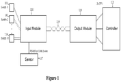
- figure 1 depicts a high level overview of a system which could be used to capture elevator safety related information and transmit it over a serial connection.
- safety related information is captured from switches [101][102][116] representing elevator doors, stop switches, inspection switches and various other safety based switches.
- a typical set of switches could be Car Door Contact Front (CDCF), Car Door Contact Rear (CDCR), Final Limit (FTSD), Safety Gear Switch (SAFGR), In-car stop switch (CST), Cartop inspection transfer switch (INCTM), Cartop inspection up (INCTU), Cartop inspection down (INCTD), Cartop Inspection Enable (INCTE), Hoistway Enable switch (INHAM), and 7 other switches wired in series to 1 input (SAFCAR) including Emergency Exit switch, Comp Chain Pull-out switch, Pendant Station Stop switch, Car Movement Lock, Cartop stop switch, Rear Cartop stop switch, and fireman stop switch.
- Other switches or combinations of switches are also possible, and the particular switches used can vary from installation to installation (e.g., based on local safety codes).
- the inventors' technology might be configured to read information from a larger number of switches than are actually present, in which case the absent switch(es) could be replaced by wire jumper(s).
- a system such as shown in figure 1 can also capture safety related information from other types of devices, such as one or more sensors [117] used to detect the position, velocity and/or speed of an elevator car.
- This capture can be achieved through use of a serialization module [118], which could be configured to read the safety related information from the switches [101][102][116] and/or various sensors [117], and to send it in serial form over a traveling cable [119] to a deserialization module [120].
- the deserialization module [120] could be configured to, once it had received the safety related information, deserialize the information and communicate it to an elevator controller [121].
- other types of safety related information could be captured and sent to the deserialization module [120] as well.
- external sensors [117] such as shown in that figure could be absolute position sensors which could be configured to detect faults as part of their position and velocity calculations.
- any faults detected by an external sensor [117] could be sent to the serialization module [118] from which they could be communicated to, and handled by, a controller [121] via the deseriailzation module [120] in a manner similar to that described herein for other types of errors.
- the serialization module [118] will be configured to send the safety related information via transmissions taking place every 5ms over a single twisted pair cable up to 1500 meters long using a non-return to zero code.
- the serialization module [118] will be configured to send the safety related information via transmissions taking place every 5ms over a single twisted pair cable up to 1500 meters long using a non-return to zero code.
- variations on that preferred approach such as the use of other transmission frequencies, other types of physical media for the traveling cable [119] (e.g., redundant transmission wires), or other types of encoding schemes (e.g., Hamming codes, return to zero codes, etc) known to those of ordinary skill in the art could also be used to implement a system shown in figure 1 .
- the serialization module [118] and deserialization module [120] will both be implemented as two separate PCB plug in boards.
- Such PCB plug in boards may be encased in housings, though it should be understood that, where the serialization module [118] and/or the deserialization module [120] is implemented as a PCB plug in board, it is not necessary for such a board to be encased in a housing for it to be used in a system such as shown in figure 1 .
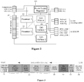
- FIG 2 that figure illustrates an exemplary set of components which could be used to implement a serialization module [118] such as shown in figure 1 .
- a serialization module [118] such as shown in figure 1 .
- the components of figure 2 are described in the context of performing four main functions: reading safety related switches [101][102][116], reading information from an external sensor [117], building a data package for transmission to the deserialization module [120], and transmitting the safety related information to the deserialization module [120].
- the functions of reading the safety related switches [101][102][116] and reading the information from the external sensor [117] can be performed using two microcontrollers [201][202] and two network interfaces (depicted as CAN interfaces [204][205]).
- These microcontrollers [201][202] would preferably be configured (e.g., through appropriately programmed software or firmware) to compare the read signals on the switch input terminals [203] (shown as 16 input terminals in figure 2 , though different numbers (e.g., more terminals in a serialization module [118] which intended to capture input from more than 16 switches) could also be used).
- microcontrollers [201][202] would also preferably each be configured to receive and cross check information from multiple external sensors [117] via the corresponding CAN interfaces [204] [205]. These comparisons and cross checks could be used to detect data corruption, short circuits or stuck-at-failures, thereby increasing the overall safety of the system.
- each microcontroller [201][202] will independently build the data package. This allows the integrity of the microcontrollers [201] [202] to be checked through comparison of the independently built data packages.
- one of the microcontrollers [201] could operate as a master microcontroller [which would transmit a data package to the communiation module [206], while the other microcontroller [202] could operate as a slave microcontroller which would not transmit a data package, but would instead monitor the communication module [206] for data packages transmitted by the master microcontroller [201].
- a slave microcontroller when a slave microcontroller detects a transmission from the master microcontroller it will compare the data package in that communication with its own independently build data package and disable the inbound transmission to the communication module if the packages are inconsistent.
- other approaches to ensuring the consistency of the data packets such as using a separate comparison component of the serialization module [118] (not shown in figure 1 ), or through use of microcontrollers in the deserialization module [120] are also possible, and will be immediately apparent to, and could be implemented without undue experimentation by, those of ordinary skill in the art in light of this disclosure.
- the information in a data package can also support increased reliability, and therefore safety, for the system.
- the microcontrollers [201][202] and/or a separate communications module [206] can be configured to create the data package to include, in addition to safety related information captured from sensors or switches, failure codes or status information determined by the serialization module [118] itself.
- microprocessors [201][202] in a serialization module could be configured to detect and generate error codes for internal errors, such as failures of components or failures to communicate with external sensors [107].
- microprocessors [201][202] could be configured to detect errors in the operation of an external sensor [107], such as by checking, for example, the sequence number, time expectation, or CRC from a frame used in communicating data from an external sensor [107], to verify that that data is valid.
- a microprocessor [201][202] from a serialization module could be configured to cross check information from those channels (e.g., by comparing the positions of the two channels and, if they do not match an expected fixed position offset, logging a communication error).
- Various types of administrative data could also be added to a data package, such as a sequence counter and a cyclic redundancy check/checksum value over the whole data carrier which could potentially be used by the deserialization module [120] to find corrupted data.
- FIG. 3 An exemplary format which could be used for a data package to be transmitted between the serialization module [118] (referred to as S3I) and the deserialization module [120] (referred to as S3O) is illustrated in figure 3 .
- the first byte of the package [301] will include the sequence counter added by the microcontrollers [201] [202].
- the next ten bytes of the package [302] will include position and speed information retrieved from external sensors (referred to in figure 3 as data from the APS, an acronym for Absolute Position Sensor).
- the following two bytes of the package [303] include information on the status of the safety related switches, with the values of the individual bits (e.g., zero or one) indicating the status of the individual switches.
- the two bytes after that [304] include information on the status of the serialization module [118].
- This status information can include information such as the manufacturer of the external sensors, whether the external sensors are properly aligned or need alignment for some reason (e.g., reading too close, reading too far, reading too left, reading too right), and whether the elevator car associated with the serialization module is ok, is recommended for service, is operating in a warning state (e.g., that it should go to its target floor then cease operation), and whether it is (or should be) stopped.
- the next one byte field in the package [305] would include codes providing information on errors.
- error codes could indicate error types such as that there is an error in the position or velocity found by an external sensor, that an internal error was detected in the serialization module, that there is a fault in a switch, that there are alignment errors, communication faults or internal errors in a sensor, or other types of error information.
- the last two bytes [306] of a package sent using the format of figure 3 will include a cyclic redundancy check value which, as described previously, can be used to identify corrupted data in the package.
- the elevator associated with the serialization module [118] which sent the package with the error codes will be immediately stopped so that the problem associated with the error codes can be addressed and the elevator can resume safe operation.
- the elevator associated with the serialization module [118] whose package was not received will preferably be stopped so that the problem which caused the loss of communication can be identified and addressed, thereby allowing the elevator to resume safe operation.
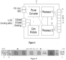
- figure 4 that figure illustrates an exemplary set of components which could be used to implement a deserialization module [120] such as shown in figure 1 .
- the discussion of figure 4 focuses on three main functions those components could perform - reading data packages received from the serialization module [118], building new data packages for transmission to the controller [121], and actually transmitting the new data packages to the controller [121] - to illustrate how those components could operate and interact with each other.
- the following discussion of the components depicted in figure 4 should be understood as being illustrative only, and should not be treated as implying limitations on the protection accorded by this document or any related document.
- the exemplary deserialization module [120] depicted in figure 4 includes parallel microcontrollers [401][402]. These microcontrollers [401][402] can be configured to retrieve the data packages sent from the serialization module [118] and check those packages for consistency with each other, as well as for internal data corruption (e.g., using sequence numbers and cyclic redundancy check values, as described previously). The microcontrollers [401][402] can also be configured to, once the data packages have been retrieved and checked, use the information from those data packages to build new data packages which will be sent to the elevator controller [121].
- a deserialization module [120] such as discussed in the context of figure 4 could be implemented in a variety of manners, including using a master/slave design similar to that discussed in the context of figure 2 .
- a master microprocessor [401] would receive data packages from the serialization module [118] and build a new data package which could be transmitted to the elevator controller [121].
- the slave microprocessor [402] would receive the same data package from the serialization module [118] and independently build a new data package.
- the slave microprocessor [402] would monitor for transmissions from the master microprocessor [401] and would compare the two independently created new data packages. If the slave microprocessor [402] detected any inconsistencies across the two independently created new data packages it would prevent the elevator controller [121] from receiving the new data package sent by the master microcontroller [401].
- FIG. 5 An exemplary format which could be used for new data packages created by a deserialization module [120] is shown in figure 5 . As shown in the labels in that figure, most of the data from the new data package is actually taken directly from the data packages received from the serialization module [118]. However, a new data package following the format of figure 5 will differ from the data package received from the serialization module [118] in that the first [501] and last [502] bytes of the new package include new sequence counter and cyclic redundancy check values determined by the deserialization module [120], rather than simply repeating the values from the original data package.
- the second byte [503] of a new data package following the format of figure 5 will include new error codes, which error codes could indicate information such as whether there was a communication error in (or loss of) communication between the serialization and deserialization modules and whether there is an error in trying to communicate data from the deserialization module to the controller (or some other type of internal error in the deserialization module).
- the elevator or elevators in the event that the error code information in a new data package indicates that an error has been detected, or an expected communication from the deserialization module is not received, the elevator or elevators whose information would be handled by that deserialization module would preferably be stopped so that the issue underlying the error or loss of communication could be resolved, and safe operation of the elevator or elevators could resume.
- these new data packages will preferably be independently created and cross checked against each other. Once they have been cross checked, the data packages will be communicated to the elevator controller [121] via a set (shown as a set of three interfaces in figure 4 , though other numbers of interfaces could be used) of redundant serial to parallel (SPI) interfaces [403].
- SPI serial to parallel
- these redundant SPI interfaces [403] will preferably be cross checked against each other (e.g., by a separate comparison component [not shown], by one or more of the microcontrollers [401][402] from the deserialization module [120], and/or by the controller [121]) to identify if any of the interfaces [403] is corrupted.
- figure 2 illustrated the example serialization module [118] as having 16 switch input terminals [203], and figures 3 and 5 illustrated exemplary data package formats as having two bytes (16 bits) of space reserved for storing information on the status of safety related switches.
Landscapes
- Engineering & Computer Science (AREA)
- Automation & Control Theory (AREA)
- Computer Networks & Wireless Communication (AREA)
- Maintenance And Inspection Apparatuses For Elevators (AREA)
- Indicating And Signalling Devices For Elevators (AREA)
Applications Claiming Priority (3)
| Application Number | Priority Date | Filing Date | Title |
|---|---|---|---|
| US201361895477P | 2013-10-25 | 2013-10-25 | |
| US14/219,494 US9452909B2 (en) | 2013-10-25 | 2014-03-19 | Safety related elevator serial communication technology |
| PCT/IB2014/002553 WO2015059565A1 (en) | 2013-10-25 | 2014-10-23 | Safety related elevator serial communication technology |
Publications (2)
| Publication Number | Publication Date |
|---|---|
| EP3060507A1 EP3060507A1 (en) | 2016-08-31 |
| EP3060507B1 true EP3060507B1 (en) | 2021-12-15 |
Family
ID=52146550
Family Applications (1)
| Application Number | Title | Priority Date | Filing Date |
|---|---|---|---|
| EP14819070.5A Active EP3060507B1 (en) | 2013-10-25 | 2014-10-23 | Safety related elevator serial communication technology |
Country Status (7)
| Country | Link |
|---|---|
| US (1) | US9452909B2 (enExample) |
| EP (1) | EP3060507B1 (enExample) |
| CN (1) | CN105764825B (enExample) |
| BR (1) | BR112016009081B1 (enExample) |
| CA (1) | CA2926769A1 (enExample) |
| ES (1) | ES2908606T3 (enExample) |
| WO (1) | WO2015059565A1 (enExample) |
Families Citing this family (12)
| Publication number | Priority date | Publication date | Assignee | Title |
|---|---|---|---|---|
| WO2016203513A1 (ja) * | 2015-06-15 | 2016-12-22 | 三菱電機株式会社 | エレベータ安全システム |
| EP3187448A1 (en) * | 2015-12-28 | 2017-07-05 | Kone Corporation | Elevator data communication arrangement |
| EP3336032B1 (en) | 2016-12-14 | 2020-10-14 | Otis Elevator Company | Elevator safety system and method of operating an elevator system |
| EP3401256B1 (en) * | 2017-05-09 | 2021-08-18 | KONE Corporation | Elevator data communication arrangement |
| EP3533741B1 (en) * | 2018-03-01 | 2021-01-06 | KONE Corporation | A communication system for transmitting safety information in an elevator system |
| EP3599203B1 (en) | 2018-07-27 | 2022-06-15 | Otis Elevator Company | Elevator safety system |
| CN108975118B (zh) * | 2018-09-03 | 2020-06-26 | 日立楼宇技术(广州)有限公司 | 电梯监控方法、装置、终端、设备、监控平台及系统 |
| CN109626165A (zh) * | 2018-12-29 | 2019-04-16 | 辽宁工程技术大学 | 一种分布式电梯状态监测系统 |
| US11993488B2 (en) | 2019-09-27 | 2024-05-28 | Otis Elevator Company | Processing service requests in a conveyance system |
| US11169877B2 (en) * | 2020-03-17 | 2021-11-09 | Allegro Microsystems, Llc | Non-volatile memory data and address encoding for safety coverage |
| CN113460818B (zh) * | 2020-03-31 | 2023-04-07 | 苏州汇川技术有限公司 | 电梯电子板通信系统、方法、设备及计算机可读存储介质 |
| EP3988489A1 (en) * | 2020-10-21 | 2022-04-27 | KONE Corporation | Elevator communication system |
Family Cites Families (38)
| Publication number | Priority date | Publication date | Assignee | Title |
|---|---|---|---|---|
| US3807531A (en) * | 1973-03-12 | 1974-04-30 | Westinghouse Electric Corp | Elevator system |
| US3841443A (en) * | 1973-09-13 | 1974-10-15 | Westinghouse Electric Corp | Elevator system |
| US4397377A (en) * | 1981-07-23 | 1983-08-09 | Westinghouse Electric Corp. | Elevator system |
| US4473133A (en) * | 1982-12-06 | 1984-09-25 | Westinghouse Electric Corp. | Elevator system |
| US4497391A (en) | 1983-10-27 | 1985-02-05 | Otis Elevator Company | Modular operational elevator control system |
| JPS62230578A (ja) * | 1986-03-31 | 1987-10-09 | 三菱電機株式会社 | エレベ−タかごの位置表示装置 |
| US4823914A (en) * | 1987-06-24 | 1989-04-25 | Elevator Performance Technologies, Inc. | Status line monitoring system and method of using same |
| JPH0398972A (ja) * | 1989-09-08 | 1991-04-24 | Mitsubishi Electric Corp | エレベータの制御装置 |
| FI98362C (fi) * | 1991-07-16 | 1997-06-10 | Kone Oy | Menetelmä hissiryhmän modernisoimiseksi |
| JPH06227766A (ja) | 1993-02-01 | 1994-08-16 | Hitachi Ltd | エレベーターの信号伝送方式 |
| FI93339C (fi) | 1993-03-17 | 1995-03-27 | Kone Oy | Menetelmä hissin ohjaustietojen toimittamiseksi, tallentamiseksi ja näyttämiseksi |
| US5551532A (en) | 1994-02-28 | 1996-09-03 | Otis Elevator Company | Method for transmitting messages in an elevator communications system |
| TW475919B (en) | 1997-08-20 | 2002-02-11 | Lg Otis Elevator Co | An elevator control system |
| US6173814B1 (en) | 1999-03-04 | 2001-01-16 | Otis Elevator Company | Electronic safety system for elevators having a dual redundant safety bus |
| US6672429B1 (en) | 2000-03-10 | 2004-01-06 | Thyssen Elevator Capital Corp. | Encoding system for communicating with elevator I/O devices |
| JP2002003108A (ja) | 2000-06-20 | 2002-01-09 | Mitsubishi Electric Corp | エレベータ群管理システム |
| ZA200307740B (en) | 2002-10-29 | 2004-07-02 | Inventio Ag | Device and method for remote maintenance of a lift. |
| FI113754B (fi) | 2003-09-10 | 2004-06-15 | Kone Corp | Hissin ohjaus |
| EP1737174B1 (en) | 2004-04-16 | 2015-05-27 | Thine Electronics, Inc. | Transmitter circuit, receiver circuit, data transmitting method and system |
| ES2293392T5 (es) | 2005-01-07 | 2011-07-20 | Thyssenkrupp Elevator Ag | Ascensor con sistema de control. |
| DE102006013578B4 (de) * | 2006-03-22 | 2008-03-27 | Phoenix Contact Gmbh & Co. Kg | Verfahren und Steuer- und Datenübertragungsanlage zum Überprüfen des Einbauortes eines sicheren Kommunikationsteilnehmers |
| FI118382B (fi) | 2006-06-13 | 2007-10-31 | Kone Corp | Hissijärjestelmä |
| SG144027A1 (en) | 2006-12-21 | 2008-07-29 | Inventio Ag | Method and system for modernisation of a lift installation |
| FI20070486L (fi) | 2007-01-03 | 2008-07-04 | Kone Corp | Hissin turvajärjestely |
| FI119508B (fi) | 2007-04-03 | 2008-12-15 | Kone Corp | Vikaturvallinen tehonohjauslaitteisto |
| ES2499340T3 (es) | 2007-08-07 | 2014-09-29 | Thyssenkrupp Elevator Ag | Sistema de elevador |
| US8151943B2 (en) | 2007-08-21 | 2012-04-10 | De Groot Pieter J | Method of controlling intelligent destination elevators with selected operation modes |
| FI120301B (fi) * | 2007-11-26 | 2009-09-15 | Kone Corp | Hissijärjestelmä |
| WO2009132697A1 (de) | 2008-04-29 | 2009-11-05 | Inventio Ag | Aufzugsanlage und rufsteuerung zur verwendung in einer aufzugsanlage |
| EP2117144A1 (en) | 2008-05-09 | 2009-11-11 | Inventio Ag | A master-less time division multiplexing method for communicating safety states |
| US8875156B2 (en) * | 2008-09-30 | 2014-10-28 | Rockwell Automation Technologies, Inc. | Remote object data property replication method and system |
| WO2010069347A1 (en) | 2008-12-18 | 2010-06-24 | Otis Elevator Company | Access control system and access control method for a people conveyor control system |
| FI121065B (fi) | 2009-03-05 | 2010-06-30 | Kone Corp | Hissijärjestelmä |
| FI121423B (fi) | 2009-04-23 | 2010-11-15 | Kone Corp | Hissin turvajärjestely |
| WO2011076533A1 (de) | 2009-12-21 | 2011-06-30 | Inventio Ag | Stockwerkpositionserkennungsvorrichtung |
| SG186731A1 (en) * | 2010-06-18 | 2013-02-28 | Hitachi Ltd | Elevator system |
| US9371210B2 (en) * | 2010-09-13 | 2016-06-21 | Otis Elevator Company | Elevator safety system having multiple buses |
| FI122474B (fi) * | 2010-12-01 | 2012-02-15 | Kone Corp | Hissin turvakytkentä sekä menetelmä hissin turvakytkennän toiminnallisen poikkeaman tunnistamiseksi |
-
2014
- 2014-03-19 US US14/219,494 patent/US9452909B2/en active Active
- 2014-10-23 EP EP14819070.5A patent/EP3060507B1/en active Active
- 2014-10-23 CN CN201480058006.2A patent/CN105764825B/zh active Active
- 2014-10-23 WO PCT/IB2014/002553 patent/WO2015059565A1/en not_active Ceased
- 2014-10-23 BR BR112016009081-0A patent/BR112016009081B1/pt active IP Right Grant
- 2014-10-23 CA CA2926769A patent/CA2926769A1/en not_active Abandoned
- 2014-10-23 ES ES14819070T patent/ES2908606T3/es active Active
Also Published As
| Publication number | Publication date |
|---|---|
| US20150114764A1 (en) | 2015-04-30 |
| WO2015059565A1 (en) | 2015-04-30 |
| BR112016009081B1 (pt) | 2022-10-18 |
| CN105764825A (zh) | 2016-07-13 |
| BR112016009081A2 (enExample) | 2017-08-01 |
| US9452909B2 (en) | 2016-09-27 |
| CA2926769A1 (en) | 2015-04-30 |
| EP3060507A1 (en) | 2016-08-31 |
| CN105764825B (zh) | 2018-06-05 |
| ES2908606T3 (es) | 2022-05-03 |
Similar Documents
| Publication | Publication Date | Title |
|---|---|---|
| EP3060507B1 (en) | Safety related elevator serial communication technology | |
| CN101557278B (zh) | 用于失效保护地传输的方法、安全开关装置和控制单元 | |
| US7624219B2 (en) | Bus node | |
| RU2665890C2 (ru) | Система управления и передачи данных, шлюзовой модуль, модуль ввода/вывода и способ управления процессами | |
| US8959405B2 (en) | Signal transmission device for elevator | |
| JP6734029B2 (ja) | プロセス制御システム内で、オンオフバルブをコントローラに通信可能に接続する方法、装置、及び記憶媒体 | |
| CN101647234B (zh) | 用于安全的周期性传输待传输的处理数据的方法及系统 | |
| EP2362570B1 (en) | Communication circuit, communication network, and connecting apparatus | |
| US9367416B2 (en) | Safety circuit of an elevator, and method for identifying a functional nonconformance of a safety circuit of an elevator | |
| CN108028791A (zh) | 井道通信系统 | |
| KR101406685B1 (ko) | 분산형 배터리 관리 시스템 및 분산형 배터리 관리 방법 | |
| US7844865B2 (en) | Bus module for connection to a bus system and use of such a bus module in an AS-i bus system | |
| US20140107863A1 (en) | Vehicle Control Device, Vehicle Control System | |
| CN111094164A (zh) | 与建筑物相关的人员运送系统的现场设备的状态检查 | |
| US20020128986A1 (en) | Communication system for franking system | |
| US7808917B2 (en) | Method and system for transmitting telegrams | |
| US7836224B2 (en) | Method and system for transmitting data of a data type to be transmitted cyclically and of a data type which can be transmitted acyclically via a common transmission channel | |
| US6725419B1 (en) | Automation system and method for operating an automation system | |
| CN111698016B (zh) | 用于数据传输的设备和方法 | |
| EP1223710A2 (en) | A control system for actuators and a method for controlling actuators | |
| US12360936B2 (en) | Interconnect bus safety | |
| JP2019528625A (ja) | データパケットをセンサから制御装置へ伝送するための方法、センサおよび制御装置 | |
| Rofar et al. | Functional safety specification of communication profile PROFIsafe | |
| JPS6394733A (ja) | 信号伝送装置 |
Legal Events
| Date | Code | Title | Description |
|---|---|---|---|
| PUAI | Public reference made under article 153(3) epc to a published international application that has entered the european phase |
Free format text: ORIGINAL CODE: 0009012 |
|
| 17P | Request for examination filed |
Effective date: 20160418 |
|
| AK | Designated contracting states |
Kind code of ref document: A1 Designated state(s): AL AT BE BG CH CY CZ DE DK EE ES FI FR GB GR HR HU IE IS IT LI LT LU LV MC MK MT NL NO PL PT RO RS SE SI SK SM TR |
|
| AX | Request for extension of the european patent |
Extension state: BA ME |
|
| DAX | Request for extension of the european patent (deleted) | ||
| RAP1 | Party data changed (applicant data changed or rights of an application transferred) |
Owner name: THYSSENKRUPP ELEVATOR AG |
|
| RAP1 | Party data changed (applicant data changed or rights of an application transferred) |
Owner name: THYSSENKRUPP ELEVATOR INNOVATION AND OPERATIONS AG |
|
| GRAP | Despatch of communication of intention to grant a patent |
Free format text: ORIGINAL CODE: EPIDOSNIGR1 |
|
| STAA | Information on the status of an ep patent application or granted ep patent |
Free format text: STATUS: GRANT OF PATENT IS INTENDED |
|
| INTG | Intention to grant announced |
Effective date: 20210706 |
|
| RAP3 | Party data changed (applicant data changed or rights of an application transferred) |
Owner name: TK ELEVATOR INNOVATION AND OPERATIONS GMBH |
|
| GRAS | Grant fee paid |
Free format text: ORIGINAL CODE: EPIDOSNIGR3 |
|
| GRAA | (expected) grant |
Free format text: ORIGINAL CODE: 0009210 |
|
| STAA | Information on the status of an ep patent application or granted ep patent |
Free format text: STATUS: THE PATENT HAS BEEN GRANTED |
|
| AK | Designated contracting states |
Kind code of ref document: B1 Designated state(s): AL AT BE BG CH CY CZ DE DK EE ES FI FR GB GR HR HU IE IS IT LI LT LU LV MC MK MT NL NO PL PT RO RS SE SI SK SM TR |
|
| REG | Reference to a national code |
Ref country code: GB Ref legal event code: FG4D Ref country code: CH Ref legal event code: EP |
|
| REG | Reference to a national code |
Ref country code: IE Ref legal event code: FG4D Ref country code: DE Ref legal event code: R096 Ref document number: 602014081759 Country of ref document: DE |
|
| REG | Reference to a national code |
Ref country code: AT Ref legal event code: REF Ref document number: 1455358 Country of ref document: AT Kind code of ref document: T Effective date: 20220115 |
|
| REG | Reference to a national code |
Ref country code: FI Ref legal event code: FGE |
|
| REG | Reference to a national code |
Ref country code: LT Ref legal event code: MG9D |
|
| REG | Reference to a national code |
Ref country code: NL Ref legal event code: MP Effective date: 20211215 |
|
| PG25 | Lapsed in a contracting state [announced via postgrant information from national office to epo] |
Ref country code: RS Free format text: LAPSE BECAUSE OF FAILURE TO SUBMIT A TRANSLATION OF THE DESCRIPTION OR TO PAY THE FEE WITHIN THE PRESCRIBED TIME-LIMIT Effective date: 20211215 Ref country code: LT Free format text: LAPSE BECAUSE OF FAILURE TO SUBMIT A TRANSLATION OF THE DESCRIPTION OR TO PAY THE FEE WITHIN THE PRESCRIBED TIME-LIMIT Effective date: 20211215 Ref country code: BG Free format text: LAPSE BECAUSE OF FAILURE TO SUBMIT A TRANSLATION OF THE DESCRIPTION OR TO PAY THE FEE WITHIN THE PRESCRIBED TIME-LIMIT Effective date: 20220315 |
|
| REG | Reference to a national code |
Ref country code: ES Ref legal event code: FG2A Ref document number: 2908606 Country of ref document: ES Kind code of ref document: T3 Effective date: 20220503 |
|
| REG | Reference to a national code |
Ref country code: AT Ref legal event code: MK05 Ref document number: 1455358 Country of ref document: AT Kind code of ref document: T Effective date: 20211215 |
|
| PG25 | Lapsed in a contracting state [announced via postgrant information from national office to epo] |
Ref country code: SE Free format text: LAPSE BECAUSE OF FAILURE TO SUBMIT A TRANSLATION OF THE DESCRIPTION OR TO PAY THE FEE WITHIN THE PRESCRIBED TIME-LIMIT Effective date: 20211215 Ref country code: NO Free format text: LAPSE BECAUSE OF FAILURE TO SUBMIT A TRANSLATION OF THE DESCRIPTION OR TO PAY THE FEE WITHIN THE PRESCRIBED TIME-LIMIT Effective date: 20220315 Ref country code: LV Free format text: LAPSE BECAUSE OF FAILURE TO SUBMIT A TRANSLATION OF THE DESCRIPTION OR TO PAY THE FEE WITHIN THE PRESCRIBED TIME-LIMIT Effective date: 20211215 Ref country code: HR Free format text: LAPSE BECAUSE OF FAILURE TO SUBMIT A TRANSLATION OF THE DESCRIPTION OR TO PAY THE FEE WITHIN THE PRESCRIBED TIME-LIMIT Effective date: 20211215 Ref country code: GR Free format text: LAPSE BECAUSE OF FAILURE TO SUBMIT A TRANSLATION OF THE DESCRIPTION OR TO PAY THE FEE WITHIN THE PRESCRIBED TIME-LIMIT Effective date: 20220316 |
|
| PG25 | Lapsed in a contracting state [announced via postgrant information from national office to epo] |
Ref country code: NL Free format text: LAPSE BECAUSE OF FAILURE TO SUBMIT A TRANSLATION OF THE DESCRIPTION OR TO PAY THE FEE WITHIN THE PRESCRIBED TIME-LIMIT Effective date: 20211215 |
|
| PG25 | Lapsed in a contracting state [announced via postgrant information from national office to epo] |
Ref country code: SM Free format text: LAPSE BECAUSE OF FAILURE TO SUBMIT A TRANSLATION OF THE DESCRIPTION OR TO PAY THE FEE WITHIN THE PRESCRIBED TIME-LIMIT Effective date: 20211215 Ref country code: SK Free format text: LAPSE BECAUSE OF FAILURE TO SUBMIT A TRANSLATION OF THE DESCRIPTION OR TO PAY THE FEE WITHIN THE PRESCRIBED TIME-LIMIT Effective date: 20211215 Ref country code: RO Free format text: LAPSE BECAUSE OF FAILURE TO SUBMIT A TRANSLATION OF THE DESCRIPTION OR TO PAY THE FEE WITHIN THE PRESCRIBED TIME-LIMIT Effective date: 20211215 Ref country code: PT Free format text: LAPSE BECAUSE OF FAILURE TO SUBMIT A TRANSLATION OF THE DESCRIPTION OR TO PAY THE FEE WITHIN THE PRESCRIBED TIME-LIMIT Effective date: 20220418 Ref country code: EE Free format text: LAPSE BECAUSE OF FAILURE TO SUBMIT A TRANSLATION OF THE DESCRIPTION OR TO PAY THE FEE WITHIN THE PRESCRIBED TIME-LIMIT Effective date: 20211215 Ref country code: CZ Free format text: LAPSE BECAUSE OF FAILURE TO SUBMIT A TRANSLATION OF THE DESCRIPTION OR TO PAY THE FEE WITHIN THE PRESCRIBED TIME-LIMIT Effective date: 20211215 |
|
| PG25 | Lapsed in a contracting state [announced via postgrant information from national office to epo] |
Ref country code: PL Free format text: LAPSE BECAUSE OF FAILURE TO SUBMIT A TRANSLATION OF THE DESCRIPTION OR TO PAY THE FEE WITHIN THE PRESCRIBED TIME-LIMIT Effective date: 20211215 Ref country code: AT Free format text: LAPSE BECAUSE OF FAILURE TO SUBMIT A TRANSLATION OF THE DESCRIPTION OR TO PAY THE FEE WITHIN THE PRESCRIBED TIME-LIMIT Effective date: 20211215 |
|
| REG | Reference to a national code |
Ref country code: DE Ref legal event code: R097 Ref document number: 602014081759 Country of ref document: DE |
|
| PG25 | Lapsed in a contracting state [announced via postgrant information from national office to epo] |
Ref country code: IS Free format text: LAPSE BECAUSE OF FAILURE TO SUBMIT A TRANSLATION OF THE DESCRIPTION OR TO PAY THE FEE WITHIN THE PRESCRIBED TIME-LIMIT Effective date: 20220415 |
|
| PLBE | No opposition filed within time limit |
Free format text: ORIGINAL CODE: 0009261 |
|
| STAA | Information on the status of an ep patent application or granted ep patent |
Free format text: STATUS: NO OPPOSITION FILED WITHIN TIME LIMIT |
|
| PG25 | Lapsed in a contracting state [announced via postgrant information from national office to epo] |
Ref country code: DK Free format text: LAPSE BECAUSE OF FAILURE TO SUBMIT A TRANSLATION OF THE DESCRIPTION OR TO PAY THE FEE WITHIN THE PRESCRIBED TIME-LIMIT Effective date: 20211215 Ref country code: AL Free format text: LAPSE BECAUSE OF FAILURE TO SUBMIT A TRANSLATION OF THE DESCRIPTION OR TO PAY THE FEE WITHIN THE PRESCRIBED TIME-LIMIT Effective date: 20211215 |
|
| 26N | No opposition filed |
Effective date: 20220916 |
|
| PG25 | Lapsed in a contracting state [announced via postgrant information from national office to epo] |
Ref country code: SI Free format text: LAPSE BECAUSE OF FAILURE TO SUBMIT A TRANSLATION OF THE DESCRIPTION OR TO PAY THE FEE WITHIN THE PRESCRIBED TIME-LIMIT Effective date: 20211215 |
|
| PG25 | Lapsed in a contracting state [announced via postgrant information from national office to epo] |
Ref country code: MC Free format text: LAPSE BECAUSE OF FAILURE TO SUBMIT A TRANSLATION OF THE DESCRIPTION OR TO PAY THE FEE WITHIN THE PRESCRIBED TIME-LIMIT Effective date: 20211215 Ref country code: IT Free format text: LAPSE BECAUSE OF FAILURE TO SUBMIT A TRANSLATION OF THE DESCRIPTION OR TO PAY THE FEE WITHIN THE PRESCRIBED TIME-LIMIT Effective date: 20211215 |
|
| REG | Reference to a national code |
Ref country code: BE Ref legal event code: MM Effective date: 20221031 |
|
| GBPC | Gb: european patent ceased through non-payment of renewal fee |
Effective date: 20221023 |
|
| PG25 | Lapsed in a contracting state [announced via postgrant information from national office to epo] |
Ref country code: LU Free format text: LAPSE BECAUSE OF NON-PAYMENT OF DUE FEES Effective date: 20221023 |
|
| P01 | Opt-out of the competence of the unified patent court (upc) registered |
Effective date: 20230526 |
|
| PG25 | Lapsed in a contracting state [announced via postgrant information from national office to epo] |
Ref country code: BE Free format text: LAPSE BECAUSE OF NON-PAYMENT OF DUE FEES Effective date: 20221031 |
|
| PG25 | Lapsed in a contracting state [announced via postgrant information from national office to epo] |
Ref country code: IE Free format text: LAPSE BECAUSE OF NON-PAYMENT OF DUE FEES Effective date: 20221023 Ref country code: GB Free format text: LAPSE BECAUSE OF NON-PAYMENT OF DUE FEES Effective date: 20221023 |
|
| PG25 | Lapsed in a contracting state [announced via postgrant information from national office to epo] |
Ref country code: HU Free format text: LAPSE BECAUSE OF FAILURE TO SUBMIT A TRANSLATION OF THE DESCRIPTION OR TO PAY THE FEE WITHIN THE PRESCRIBED TIME-LIMIT; INVALID AB INITIO Effective date: 20141023 |
|
| PG25 | Lapsed in a contracting state [announced via postgrant information from national office to epo] |
Ref country code: CY Free format text: LAPSE BECAUSE OF FAILURE TO SUBMIT A TRANSLATION OF THE DESCRIPTION OR TO PAY THE FEE WITHIN THE PRESCRIBED TIME-LIMIT Effective date: 20211215 |
|
| PG25 | Lapsed in a contracting state [announced via postgrant information from national office to epo] |
Ref country code: MK Free format text: LAPSE BECAUSE OF FAILURE TO SUBMIT A TRANSLATION OF THE DESCRIPTION OR TO PAY THE FEE WITHIN THE PRESCRIBED TIME-LIMIT Effective date: 20211215 |
|
| PG25 | Lapsed in a contracting state [announced via postgrant information from national office to epo] |
Ref country code: MT Free format text: LAPSE BECAUSE OF FAILURE TO SUBMIT A TRANSLATION OF THE DESCRIPTION OR TO PAY THE FEE WITHIN THE PRESCRIBED TIME-LIMIT Effective date: 20211215 |
|
| PGFP | Annual fee paid to national office [announced via postgrant information from national office to epo] |
Ref country code: DE Payment date: 20241021 Year of fee payment: 11 |
|
| PGFP | Annual fee paid to national office [announced via postgrant information from national office to epo] |
Ref country code: FI Payment date: 20241025 Year of fee payment: 11 |
|
| PGFP | Annual fee paid to national office [announced via postgrant information from national office to epo] |
Ref country code: FR Payment date: 20241021 Year of fee payment: 11 |
|
| PGFP | Annual fee paid to national office [announced via postgrant information from national office to epo] |
Ref country code: ES Payment date: 20241127 Year of fee payment: 11 |
|
| PGFP | Annual fee paid to national office [announced via postgrant information from national office to epo] |
Ref country code: CH Payment date: 20241101 Year of fee payment: 11 |
|
| REG | Reference to a national code |
Ref country code: CH Ref legal event code: U11 Free format text: ST27 STATUS EVENT CODE: U-0-0-U10-U11 (AS PROVIDED BY THE NATIONAL OFFICE) Effective date: 20251101 |
|
| PG25 | Lapsed in a contracting state [announced via postgrant information from national office to epo] |
Ref country code: TR Free format text: LAPSE BECAUSE OF FAILURE TO SUBMIT A TRANSLATION OF THE DESCRIPTION OR TO PAY THE FEE WITHIN THE PRESCRIBED TIME-LIMIT Effective date: 20211215 |