EP3056626A1 - Fugendichtband mit vorbestimmter Geometrie und Dichtanordnung mit derartigem Fugendichtband - Google Patents
Fugendichtband mit vorbestimmter Geometrie und Dichtanordnung mit derartigem Fugendichtband Download PDFInfo
- Publication number
- EP3056626A1 EP3056626A1 EP15155102.5A EP15155102A EP3056626A1 EP 3056626 A1 EP3056626 A1 EP 3056626A1 EP 15155102 A EP15155102 A EP 15155102A EP 3056626 A1 EP3056626 A1 EP 3056626A1
- Authority
- EP
- European Patent Office
- Prior art keywords
- sealing
- joint
- sealing element
- profile
- component
- Prior art date
- Legal status (The legal status is an assumption and is not a legal conclusion. Google has not performed a legal analysis and makes no representation as to the accuracy of the status listed.)
- Withdrawn
Links
- 238000007789 sealing Methods 0.000 title claims abstract description 345
- 239000012790 adhesive layer Substances 0.000 claims abstract description 38
- 239000000463 material Substances 0.000 claims description 35
- 239000007787 solid Substances 0.000 claims description 20
- 239000010410 layer Substances 0.000 claims description 18
- 239000002985 plastic film Substances 0.000 claims description 9
- 229920006255 plastic film Polymers 0.000 claims description 9
- 230000001413 cellular effect Effects 0.000 claims description 7
- 229920001971 elastomer Polymers 0.000 claims description 7
- 229920005830 Polyurethane Foam Polymers 0.000 claims description 6
- 239000011496 polyurethane foam Substances 0.000 claims description 6
- 239000000779 smoke Substances 0.000 abstract description 8
- 239000006260 foam Substances 0.000 description 27
- 229910052602 gypsum Inorganic materials 0.000 description 10
- 239000010440 gypsum Substances 0.000 description 10
- 239000000565 sealant Substances 0.000 description 10
- 239000003566 sealing material Substances 0.000 description 7
- 239000000654 additive Substances 0.000 description 6
- 230000006835 compression Effects 0.000 description 6
- 238000007906 compression Methods 0.000 description 6
- 238000010521 absorption reaction Methods 0.000 description 5
- 239000000853 adhesive Substances 0.000 description 5
- 230000001070 adhesive effect Effects 0.000 description 5
- 239000007789 gas Substances 0.000 description 5
- 150000001875 compounds Chemical class 0.000 description 4
- 238000010276 construction Methods 0.000 description 4
- 238000005259 measurement Methods 0.000 description 4
- 238000006243 chemical reaction Methods 0.000 description 3
- 239000011888 foil Substances 0.000 description 3
- 238000004519 manufacturing process Methods 0.000 description 3
- RNFJDJUURJAICM-UHFFFAOYSA-N 2,2,4,4,6,6-hexaphenoxy-1,3,5-triaza-2$l^{5},4$l^{5},6$l^{5}-triphosphacyclohexa-1,3,5-triene Chemical compound N=1P(OC=2C=CC=CC=2)(OC=2C=CC=CC=2)=NP(OC=2C=CC=CC=2)(OC=2C=CC=CC=2)=NP=1(OC=1C=CC=CC=1)OC1=CC=CC=C1 RNFJDJUURJAICM-UHFFFAOYSA-N 0.000 description 2
- -1 For example Substances 0.000 description 2
- 238000005520 cutting process Methods 0.000 description 2
- 239000003063 flame retardant Substances 0.000 description 2
- 239000006261 foam material Substances 0.000 description 2
- 238000009434 installation Methods 0.000 description 2
- 238000000034 method Methods 0.000 description 2
- 230000035515 penetration Effects 0.000 description 2
- 238000003825 pressing Methods 0.000 description 2
- 238000003892 spreading Methods 0.000 description 2
- 239000007858 starting material Substances 0.000 description 2
- NIXOWILDQLNWCW-UHFFFAOYSA-M Acrylate Chemical compound [O-]C(=O)C=C NIXOWILDQLNWCW-UHFFFAOYSA-M 0.000 description 1
- 239000004831 Hot glue Substances 0.000 description 1
- 239000004698 Polyethylene Substances 0.000 description 1
- 239000004826 Synthetic adhesive Substances 0.000 description 1
- 230000015572 biosynthetic process Effects 0.000 description 1
- 239000003795 chemical substances by application Substances 0.000 description 1
- 230000001419 dependent effect Effects 0.000 description 1
- 238000001125 extrusion Methods 0.000 description 1
- 239000004744 fabric Substances 0.000 description 1
- 229920001821 foam rubber Polymers 0.000 description 1
- 239000003365 glass fiber Substances 0.000 description 1
- 239000011507 gypsum plaster Substances 0.000 description 1
- 239000012784 inorganic fiber Substances 0.000 description 1
- 230000002045 lasting effect Effects 0.000 description 1
- 239000002184 metal Substances 0.000 description 1
- 239000011490 mineral wool Substances 0.000 description 1
- 239000000203 mixture Substances 0.000 description 1
- 239000004033 plastic Substances 0.000 description 1
- 229920003023 plastic Polymers 0.000 description 1
- 229920000573 polyethylene Polymers 0.000 description 1
- 229920001296 polysiloxane Polymers 0.000 description 1
- 239000011148 porous material Substances 0.000 description 1
- 238000002360 preparation method Methods 0.000 description 1
- 230000001007 puffing effect Effects 0.000 description 1
- 230000000630 rising effect Effects 0.000 description 1
- 239000002689 soil Substances 0.000 description 1
- 239000007921 spray Substances 0.000 description 1
- 239000000126 substance Substances 0.000 description 1
- 239000000758 substrate Substances 0.000 description 1
Images




Classifications
-
- E—FIXED CONSTRUCTIONS
- E04—BUILDING
- E04B—GENERAL BUILDING CONSTRUCTIONS; WALLS, e.g. PARTITIONS; ROOFS; FLOORS; CEILINGS; INSULATION OR OTHER PROTECTION OF BUILDINGS
- E04B1/00—Constructions in general; Structures which are not restricted either to walls, e.g. partitions, or floors or ceilings or roofs
- E04B1/62—Insulation or other protection; Elements or use of specified material therefor
- E04B1/92—Protection against other undesired influences or dangers
- E04B1/94—Protection against other undesired influences or dangers against fire
- E04B1/948—Fire-proof sealings or joints
-
- C—CHEMISTRY; METALLURGY
- C09—DYES; PAINTS; POLISHES; NATURAL RESINS; ADHESIVES; COMPOSITIONS NOT OTHERWISE PROVIDED FOR; APPLICATIONS OF MATERIALS NOT OTHERWISE PROVIDED FOR
- C09J—ADHESIVES; NON-MECHANICAL ASPECTS OF ADHESIVE PROCESSES IN GENERAL; ADHESIVE PROCESSES NOT PROVIDED FOR ELSEWHERE; USE OF MATERIALS AS ADHESIVES
- C09J7/00—Adhesives in the form of films or foils
- C09J7/20—Adhesives in the form of films or foils characterised by their carriers
- C09J7/22—Plastics; Metallised plastics
- C09J7/26—Porous or cellular plastics
-
- E—FIXED CONSTRUCTIONS
- E04—BUILDING
- E04B—GENERAL BUILDING CONSTRUCTIONS; WALLS, e.g. PARTITIONS; ROOFS; FLOORS; CEILINGS; INSULATION OR OTHER PROTECTION OF BUILDINGS
- E04B1/00—Constructions in general; Structures which are not restricted either to walls, e.g. partitions, or floors or ceilings or roofs
- E04B1/62—Insulation or other protection; Elements or use of specified material therefor
- E04B1/92—Protection against other undesired influences or dangers
- E04B1/94—Protection against other undesired influences or dangers against fire
- E04B1/946—Protection against smoke or toxic gases
-
- E—FIXED CONSTRUCTIONS
- E04—BUILDING
- E04B—GENERAL BUILDING CONSTRUCTIONS; WALLS, e.g. PARTITIONS; ROOFS; FLOORS; CEILINGS; INSULATION OR OTHER PROTECTION OF BUILDINGS
- E04B1/00—Constructions in general; Structures which are not restricted either to walls, e.g. partitions, or floors or ceilings or roofs
- E04B1/62—Insulation or other protection; Elements or use of specified material therefor
- E04B1/92—Protection against other undesired influences or dangers
- E04B1/94—Protection against other undesired influences or dangers against fire
- E04B1/947—Protection against other undesired influences or dangers against fire by closing openings in walls or the like in the case of fire
-
- E—FIXED CONSTRUCTIONS
- E04—BUILDING
- E04B—GENERAL BUILDING CONSTRUCTIONS; WALLS, e.g. PARTITIONS; ROOFS; FLOORS; CEILINGS; INSULATION OR OTHER PROTECTION OF BUILDINGS
- E04B2/00—Walls, e.g. partitions, for buildings; Wall construction with regard to insulation; Connections specially adapted to walls
- E04B2/74—Removable non-load-bearing partitions; Partitions with a free upper edge
- E04B2/7407—Removable non-load-bearing partitions; Partitions with a free upper edge assembled using frames with infill panels or coverings only; made-up of panels and a support structure incorporating posts
- E04B2/7409—Removable non-load-bearing partitions; Partitions with a free upper edge assembled using frames with infill panels or coverings only; made-up of panels and a support structure incorporating posts special measures for sound or thermal insulation, including fire protection
- E04B2/7411—Details for fire protection
-
- C—CHEMISTRY; METALLURGY
- C09—DYES; PAINTS; POLISHES; NATURAL RESINS; ADHESIVES; COMPOSITIONS NOT OTHERWISE PROVIDED FOR; APPLICATIONS OF MATERIALS NOT OTHERWISE PROVIDED FOR
- C09J—ADHESIVES; NON-MECHANICAL ASPECTS OF ADHESIVE PROCESSES IN GENERAL; ADHESIVE PROCESSES NOT PROVIDED FOR ELSEWHERE; USE OF MATERIALS AS ADHESIVES
- C09J2400/00—Presence of inorganic and organic materials
- C09J2400/20—Presence of organic materials
- C09J2400/24—Presence of a foam
-
- C—CHEMISTRY; METALLURGY
- C09—DYES; PAINTS; POLISHES; NATURAL RESINS; ADHESIVES; COMPOSITIONS NOT OTHERWISE PROVIDED FOR; APPLICATIONS OF MATERIALS NOT OTHERWISE PROVIDED FOR
- C09J—ADHESIVES; NON-MECHANICAL ASPECTS OF ADHESIVE PROCESSES IN GENERAL; ADHESIVE PROCESSES NOT PROVIDED FOR ELSEWHERE; USE OF MATERIALS AS ADHESIVES
- C09J2421/00—Presence of unspecified rubber
- C09J2421/006—Presence of unspecified rubber in the substrate
-
- C—CHEMISTRY; METALLURGY
- C09—DYES; PAINTS; POLISHES; NATURAL RESINS; ADHESIVES; COMPOSITIONS NOT OTHERWISE PROVIDED FOR; APPLICATIONS OF MATERIALS NOT OTHERWISE PROVIDED FOR
- C09J—ADHESIVES; NON-MECHANICAL ASPECTS OF ADHESIVE PROCESSES IN GENERAL; ADHESIVE PROCESSES NOT PROVIDED FOR ELSEWHERE; USE OF MATERIALS AS ADHESIVES
- C09J2475/00—Presence of polyurethane
- C09J2475/006—Presence of polyurethane in the substrate
-
- C—CHEMISTRY; METALLURGY
- C09—DYES; PAINTS; POLISHES; NATURAL RESINS; ADHESIVES; COMPOSITIONS NOT OTHERWISE PROVIDED FOR; APPLICATIONS OF MATERIALS NOT OTHERWISE PROVIDED FOR
- C09K—MATERIALS FOR MISCELLANEOUS APPLICATIONS, NOT PROVIDED FOR ELSEWHERE
- C09K21/00—Fireproofing materials
- C09K21/14—Macromolecular materials
-
- E—FIXED CONSTRUCTIONS
- E04—BUILDING
- E04B—GENERAL BUILDING CONSTRUCTIONS; WALLS, e.g. PARTITIONS; ROOFS; FLOORS; CEILINGS; INSULATION OR OTHER PROTECTION OF BUILDINGS
- E04B1/00—Constructions in general; Structures which are not restricted either to walls, e.g. partitions, or floors or ceilings or roofs
- E04B1/62—Insulation or other protection; Elements or use of specified material therefor
- E04B1/66—Sealings
- E04B1/68—Sealings of joints, e.g. expansion joints
- E04B1/6812—Compressable seals of solid form
-
- E—FIXED CONSTRUCTIONS
- E04—BUILDING
- E04B—GENERAL BUILDING CONSTRUCTIONS; WALLS, e.g. PARTITIONS; ROOFS; FLOORS; CEILINGS; INSULATION OR OTHER PROTECTION OF BUILDINGS
- E04B1/00—Constructions in general; Structures which are not restricted either to walls, e.g. partitions, or floors or ceilings or roofs
- E04B1/62—Insulation or other protection; Elements or use of specified material therefor
- E04B1/66—Sealings
- E04B1/68—Sealings of joints, e.g. expansion joints
- E04B1/6813—Compressable seals of hollow form
-
- E—FIXED CONSTRUCTIONS
- E04—BUILDING
- E04B—GENERAL BUILDING CONSTRUCTIONS; WALLS, e.g. PARTITIONS; ROOFS; FLOORS; CEILINGS; INSULATION OR OTHER PROTECTION OF BUILDINGS
- E04B2/00—Walls, e.g. partitions, for buildings; Wall construction with regard to insulation; Connections specially adapted to walls
- E04B2/74—Removable non-load-bearing partitions; Partitions with a free upper edge
- E04B2/7407—Removable non-load-bearing partitions; Partitions with a free upper edge assembled using frames with infill panels or coverings only; made-up of panels and a support structure incorporating posts
- E04B2/7453—Removable non-load-bearing partitions; Partitions with a free upper edge assembled using frames with infill panels or coverings only; made-up of panels and a support structure incorporating posts with panels and support posts, extending from floor to ceiling
- E04B2/7457—Removable non-load-bearing partitions; Partitions with a free upper edge assembled using frames with infill panels or coverings only; made-up of panels and a support structure incorporating posts with panels and support posts, extending from floor to ceiling with wallboards attached to the outer faces of the posts, parallel to the partition
Definitions
- the present invention relates to a joint sealing strip and a sealing arrangement with such joint sealing strip for sealing building joints, in particular for sealing against sound and smoke and optionally against fire.
- the invention relates to the acoustic, smoke-proof and / or fireproof sealing of connection joints in drywall walls, especially of expansion joints.
- Connecting joints usually arise when different components meet. Connecting joints are located in the connection area to the floor slab, to the floor and to solid walls. Weight bearing or thermal influences can lead to lowering or lifting of the ceiling in buildings.
- the upper connection joint is designed as a movement joint. As expansion joints, therefore, joints for interrupting components are called to prevent stress cracks.
- the ceiling profile is designed such that a relative movement between the ceiling profile and the vertical wall components is possible.
- connection components which is part of the stud work.
- the gypsum plasterboards themselves are attached with a defined distance to the connection component.
- the sealing of the system takes place in the gap between gypsum board and ceiling. This is either a suitable Inserted sealant or the gap filled with mineral wool and provided on the surface with a sealing layer. In both cases, the material in the joint impedes the movement relatively strong, with the consequence that must be worked to achieve sufficient movement absorption with relatively large joint widths.
- the sealing of the gap with sealant has some disadvantages. It is particularly labor intensive and the seal tends to crack overstress over time. Furthermore, the seal can be made only after installation of the plasterboard and requires two-sided access to the finished drywall. In addition, this approach is prone to error as the user himself must dose the right amount of material to adequately seal the gap. In addition, the drywall must dimension the joint in width according to the material and expansion properties of the sealant. When installing the sealant then only the gap can be filled. When extending the gap, it must be ensured that the sealant adheres sufficiently strongly to the substrate and can absorb the resulting tensile forces.
- the object of the present invention is therefore to provide a joint sealing strip which avoids the disadvantages of the known materials, which in particular is simpler and safer to use, simplifies the assembly of further components, a good one Sealing already in its application and ensures excellent tightness with maximum movement absorption.
- a further object of the present invention is to provide an arrangement which, in the event of a fire, allows a better sealing of the joint between two components, in particular between a dry wall and a connection component, such as a wall, ceiling or floor, and thus a better and lasting one Sealing against sound and / or smoke and possibly provides a better and more durable fire protection and can be installed reliably and error-free with less effort.
- the present invention relates to a joint sealing strip for sealing a joint between a first component and a second component, comprising a sealing element and an adhesive layer, which is characterized in that the sealing element has a predetermined geometry.
- the present invention further relates to a sealing arrangement for sealing a joint between two adjoining components, comprising at least a first component, a second component and the previously described joint sealing strip, wherein the sealing element is positioned in the upper region of the joint and configured to externally open the joint seal.
- deformable in the context of the present invention means that unevenness in the component can be compensated, against which the sealing element is pressed.
- “Plastic deformable” means that the sealing element is deformable and does not return to its original shape after deformation.
- Elastic deformable means that the sealing element is deformable and after deformation returns to its original shape, i. that the material can be reversibly deformed to a certain degree.
- intumescence in the context of the present invention means that under the action of heat, for example in case of fire, the material inflates and forms an insulating layer of flame-retardant material, ie intumescent.
- slow-burning foam is understood as meaning a foam which offers no possibility of the foam spreading through the foam, is not intrinsically inflammable and does not drip off.
- the joint sealing strip is arranged in particular on the second component, preferably a blanket.
- adheresive layer in the context of the present invention means in particular a self-adhesive layer, but may also be present in the form of positive or non-positively acting agents, such as suitable profiles or a putty material, or by means of a separately applicable adhesive or the like.
- the present invention relates to a joint sealing tape for sealing a joint between a first component and a second component, comprising a sealing element and an adhesive layer, which is characterized in that the sealing element has a predetermined geometry.
- the present invention relates to a sealing arrangement for sealing a joint between two adjoining components, comprising at least a first component, a second component and the previously described joint sealing tape, wherein the joint sealing tape is positioned in the upper region of the joint and configured to Seal the joint from the outside.
- the joint sealing strip according to the invention is particularly suitable for securely sealing a structural joint between two adjoining components in a simple manner, in particular against sound and / or smoke and optionally also against fire.
- the sealing element of the joint sealing strip must have a predetermined geometry.
- the joint sealing tape must be positioned in the upper region of the joint and configured to seal the joint from the outside.
- the sealing element it is an object of the present invention to describe the sealing element.
- the joint sealing strip according to the invention for sealing a joint between a first component and a second component, with a sealing element and an adhesive layer, is characterized in that the sealing element has a predetermined geometry.
- Geometries in the context of the present invention comprise, as already mentioned above, various cross-sectional types and cross-sectional shapes.
- Preferred cross-sectional types of the sealing element according to the present invention are solid profile and hollow profile, wherein the hollow profile may be a closed or open hollow profile.
- Solid profile and hollow profile with large profile wall thickness have the advantage that automatically creates no gap at the joint of two touching sealing elements. Hollow profiles can be compressed more, and thus absorb more movement. It is particularly preferred that the sealing element has a solid profile.
- Preferred cross-sectional shapes of the sealing element according to the present invention are round profile, polygonal profile, in particular rectangular profile, square profile, parallelogram profile, and triangular profile. Particularly preferred are round profile and rectangular profile, with rectangular profile is most preferred. However, there are also other or mixed cross-sectional shapes conceivable and possible, as long as the joint sealing strip adjacent to the installation of the sealing element to the two components and can close the gap existing between the components.
- the sealing element has a round profile.
- the sealing element has a rectangular profile.
- the sealing element has a solid profile and a round profile.
- the sealing element has a solid profile and a rectangular profile.
- the geometry of the sealing elements may be prefabricated, for example by defined cutting, extruding or pressing of suitable sealing material, or directly from flat material, for example by means of folds or rolls of flat starting material, such as fabric, in particular non-combustible material, such as inorganic fibers , For example, glass fibers, a non-woven or the like can be produced.
- suitable sealing material such as fabric, in particular non-combustible material, such as inorganic fibers , for example, glass fibers, a non-woven or the like can be produced.
- the preparation of such cross-sectional types and cross-sectional shapes is known to the person skilled in the art. It is preferred that the geometry of the sealing element is prefabricated by defined cutting or extrusion.
- the sealing element according to the invention may consist of one or more parts of a material in one piece and present, for example, as a layered body.
- the outer region and the inner region of a sealing element may define separate regions of the sealing element that have different cross-sectional shapes and / or cross-sectional types and / or may consist of different materials.
- the sealing element consists of a deformable material.
- the material can be either plastically or elastically deformable.
- the sealing elements consist at least partially, preferably completely of a material which can be restored after compression, for example foam, sponge rubber, cellular rubber or the like.
- the sealing element according to the invention preferably consists of a soft, resilient after compression foam.
- Foam material are conventional foams, such as polyethylene and polyurethane foam or cellular rubber to name.
- the foam may be an open-cell foam with very low air resistance, as well as a nearly closed-cell foam with extremely low air penetration values. Even foams with air penetration values, which lie between the two extreme cases mentioned above, can be used in the context of the present invention.
- the foam may be impregnated with an impregnate which increases the sealing properties of the foam.
- an impregnate which increases the sealing properties of the foam.
- at least the outer surface of the sealing element should be formed closed pores.
- an open-cell sealing element may be provided with a cover layer or sheathing, for example of a film, in particular plastic film. It is preferred that the sealing element consists of an open-cell polyurethane foam or of a cellular rubber.
- the sealing element consists of a slow-burning foam, such as cellular rubber or polyurethane foam.
- a slow-burning foam there is no possibility of fire spreading through the foam.
- a self-ignition is excluded in the above-mentioned foam starting materials. It is advantageous that in case of fire no dripping takes place.
- a slow-burning foam should still be at least 20%, still at least 25%, preferably still at least 30%, between 20% to 60%, between 20% to 40%, preferably between 25%, in a temperature range between 500 ° C. and 800 ° C. up to 30% of its initial volume.
- a slow-burning foam in a temperature range between 500 ° C to 800 ° C should still at least 10%, at least 20%, preferably still at least 30%, between 10% to 40%, between 10% to 30%, preferably between 15% up to 20% of its original mass.
- the material may contain appropriate additives. Under the influence of heat, as in the case of fire, the material inflates and forms an insulating layer of flame-retardant material.
- a voluminous, insulating layer namely an ash layer
- Heat reaction with each other can be formed.
- the voluminous insulating layer can be formed by puffing a single compound which releases gases when no heat is applied to a chemical reaction between two compounds.
- Such systems are known to the person skilled in the art under the term physical intumescence and can also be used according to the invention. Both systems can be used alone or together as a combination according to the invention.
- the sealing element consists of an open-cell foam.
- the sealing element consists of a closed-cell foam.
- the sealing element consists of an open-cell polyurethane foam.
- the sealing element consists of a cellular rubber.
- the sealing element is at least over a part of its circumference fixed by a cover layer or sheath, for example, a film, in particular plastic film, surrounded.
- the sealing element is firmly surrounded over its entire circumference by a covering layer or sheathing, for example of a film, in particular plastic film.
- a covering layer or sheathing for example of a film, in particular plastic film.
- an open-cell foam material can be used for the sealing element.
- the sealing element may be advantageous to provide with a projecting film, such as a film strip.
- the adhesive layer of the jointing sealing strip according to the invention can be in the form of an adhesive layer, in particular a self-adhesive layer, in the form of positive or non-positive acting means, such as suitable profilings or a putty material, or by means of a separately applicable adhesive or the like.
- Synthetic adhesives such as acrylate adhesives or hot melt adhesives can be used in the present invention, but silicone based adhesives are also conceivable.
- the adhesive layer of the joint sealing tape is a self-adhesive layer.
- the positioning of the joint sealing strip to the component can be effected by means for attachment, for example in the form of just-mentioned adhesive layer, in particular a self-adhesive layer, in the form of positive or non-positively acting means, such as suitable profiles or a putty material, by means of a separately applicable adhesive or the like. Preference is given to positioning the joint sealing strip on the connection component by means of a self-adhesive layer.
- the attachment, in particular the bonding, of the joint sealing strip according to the invention can be performed flat or only selectively, preferably by pressing.
- the bonding is only necessary for a temporary fixation of the joint sealing tape. Once the gypsum board is mounted, precompression keeps the joint sealing tape in place.
- the sealing element is provided with a protruding foil
- the adhesive layer is applied to the protruding foil strip, this is folded over and then the joint sealing strip is attached to the component.
- the dimension and materials of the joint sealing tape are chosen according to the intended use of the joint sealing tape.
- the dimension of the joint sealing strip is selected depending on the profiles used and the material used. The dimension must be chosen so that the joint sealing tape fills the gap between the plasterboard and the ceiling and sealingly abuts both the ceiling and the plasterboard. Should a vertical movement of the plasterboard be approved, the joint sealing tape must follow the movement of the plasterboard, so that the contact with the plasterboard does not break and no gap between joint sealing tape and plasterboard can arise.
- the sealing element of the joint sealing strip is preferably made of resilient and compressible material and is precompressed accordingly during assembly of the plasterboard so that a downward movement of the plasterboard, whereby the gap between the latter and the ceiling is increased, can be followed. The preset freedom of movement of the plasterboard thus determines the dimension of the sealing element and thus the joint sealing strip.
- the height of the narrow side of a rectangular sealing element is selected depending on the desired application of the joint sealing strip, with a simple Plankung the height selected approximately in the thickness of a plasterboard and double planking the height about twice the thickness of a plasterboard becomes. But it is also possible to use with simple planking designed for double planking joint sealing tape.
- the material and geometry of the sealing element can be chosen such that its hardness or compressibility is adjusted so that the sealing elements are compressed to a defined height solely by the weight of the plasterboard in the bottom region, for example by a two-layered construction of the sealing element made of foams with different compression density.
- a correct distance between soil and plasterboard can be set without further measuring. This is particularly necessary if damage to the plasterboard is to be prevented by rising wet.
- the joint-sealing tape according to the invention is positioned after the attachment of a first component to a second component, in particular arranged in abutment with the first component.
- the first component is a frame profile of a drywall stand, such as a U-profile
- the second component is a wall, ceiling, or floor of a building.
- the first component is a U-profile
- the second component is a ceiling.
- connection components such as a ceiling, wall or floor, positioned on or in front of that U-profile and on the Connection component, preferably a ceiling, fixed.
- the plasterboard one or two layers, the front side pressed against the sealing element, so that with double planking the two plasterboard come with their upper edge in contact with the sealing element, and thereby a seal of the joint is achieved.
- the sealing element In order to allow the movement of the plasterboard (s) without creating a gap between the sealing element and the plasterboard or gypsum board at maximum movement, the sealing element must be compressed during assembly of the gypsum board (s). Once the gypsum board is mounted, precompression keeps the joint sealing tape in place. Further, any compression of any unevenness occluded by this compression.
- the material and the thickness of the sealing element is selected in each case so that the sealing element does not hinder the movement of the plasterboard (s) and at maximum joint width, the upper edge of the plasterboard (s) touches the sealing element to ensure adequate sealing against gases.
- the width of the sealing element is preferably chosen so that it corresponds approximately to twice the width of a plasterboard. It has been found that a sufficient seal can be achieved even if the width of the sealing element corresponds to the width of only one gypsum plaster board.
- the sealing tape may be partially laminated with a layer of a material which neither obstructs nor is destroyed by the movement of the plasterboard, such as a plastic film. For example, on a slide can be easily apply the positioning mark for the plasterboard.
- a seal of the joint can be achieved if the two gypsum plasterboards are mounted horizontally offset with double planking, that the outer of the two plasterboard (also referred to as outer, second plasterboard) higher (ie closer to the ceiling ) as the inner gypsum board (also referred to as inner, first gypsum board) is mounted.
- the thickness of the sealing element is selected according to the thickness of a plasterboard.
- the first, inner plasterboard is mounted such that its upper edge touches the end faces of the sealing element, with little or no precompression of the sealing element is required.
- the second, outer plasterboard is placed horizontally offset, ie it is mounted higher than the first, inner plasterboard, so that they partially covered the sealing strip.
- the sealing element and the plasterboard should seal against each other to seal the gap between the outer, second plasterboard and the sealing element, in particular against gases. This results in a seal between the sealing element and the second component, such as a ceiling, a wall or a floor, and between sealing element and outer, second plasterboard instead.
- the second component such as a ceiling, a wall or a floor
- the outer, second plasterboard remains an empty gap. This gap is completely in the case of a vertical movement of the second component or the plasterboard a movement recording available.
- the dimension of the sealing element is chosen so that its thickness is slightly larger than the thickness of a plasterboard and its height slightly more than the maximum allowable movement of the components (maximum joint width) includes.
- the plasterboard is pressed during assembly against the sealing element and slightly compressed, whereby the gap between the sealing element and plasterboard is reliable, especially against gases sealed.
- markings can be placed laterally on the joint sealing tape, a so-called positioning mark.
- the sealing tape can be laminated on one side with a layer of a material which neither obstructs nor destroys the movement of the plasterboard, such as a plastic film.
- a material which neither obstructs nor destroys the movement of the plasterboard such as a plastic film.
- on a slide can be easily apply the positioning mark for the outer, second plasterboard.
- the joint sealing tape can be applied to all types of connection joints, in which one component strikes another component. Accordingly, the joint sealing tape can be applied to all profiles, including closed profiles or wooden beams, which must be sealed to form a connection surface.
- a particularly preferred application of the joint sealing tape relates to the sealing of the profiles in the dry construction, wherein the first component is a ceiling, floor or wall profile or a metal or wooden stand of a dry construction element and the second component is a floor, a ceiling or a wall of a component, For example, a masonry or concrete element is.
- the profile may be any of the commonly used drywall profiles, whether it has a slotted or unslotted web between slotted or unslotted flanges.
- the other components are plasterboard, which fit tightly against the profiles and are fixed to the framework. In order to allow a vertical movement of the plasterboard, such as in the case of an earthquake, the plasterboard panels are mounted vertically movable at a distance to a wall, a floor or a ceiling.
- This joint is filled by the sealing element of the joint sealing strip, so that the sealing element seals the joint against sound and / or smoke and, depending on the material of the sealing element optionally also against fire.
- the joint sealing tape is applied to the Connecting joints used in drywall walls.
- the skilled person is clear that the sealing tape can also be applied to other types of building joints.
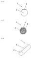
- FIGS. 1a to 1c a preferred embodiment of a joint sealing strip 1 according to the invention is shown.
- the joint sealing tape 1 comprises a sealing element 2 and an adhesive layer 3.
- the sealing element 2 has a round profile and a solid profile.
- the sealing element 2 is completely, that is surrounded over its entire circumference by a cover layer 4.
- the sealing element 2 consists of a compressible foam, optionally containing fire protection additives, and the cover layer 4 of a plastic film.
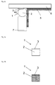
- Figure 1d is a sealing arrangement with the in FIGS. 1a to 1c shown embodiment of a joint sealing strip according to the invention, wherein the joint sealing strip 1 is positioned after attachment of a U-profile 5 on a ceiling 6 and at impact with the U-profile 5 and fixed to the ceiling 6.
- Figure 1e shows a sectional view through a finished component with the in Figure 1d shown embodiment of a sealing arrangement according to the invention, wherein the sealing element is positioned in the upper region of the joint and configured to seal the joint from the outside.
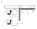
- FIG. 6 the step-by-step approach to manufacturing a finished device with the in FIGS. 1a to 1c shown embodiment of a joint sealing strip according to the invention for sealing a gap between a ceiling 6, the U-section 5 of a drywall stand and a plasterboard 7 outlined.
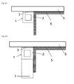
- FIGS. 2a and 2b a further preferred embodiment of a joint sealing strip 1 according to the invention is shown.
- the joint sealing tape 1 comprises a sealing element 2 and an adhesive layer 3.
- the sealing element 2 has a round profile and a solid profile.
- the sealing element 2 is completely, that is surrounded over its entire circumference by a cover layer 4.
- the sealing element 2 is provided with a projecting film strip 4a.
- the sealing element 2 consists of a compressible foam, optionally containing fire protection additives, and the cover layer 4 and the film strip 4a of a plastic film.
- Figure 2c is a sealing arrangement with the in FIGS.
- FIG. 2a and 2b shown embodiment of a joint sealing strip according to the invention, wherein the joint sealing strip 1 is positioned after attachment of a U-profile 5 on a ceiling 6 and at impact with the U-profile 5 and fixed to the ceiling 6.
- the adhesive layer 3 is mounted in this embodiment on the protruding film strip 4a, this is bent over and then attached the joint sealing tape to the component.
- Figure 2d shows a sectional view through a finished component with the in Figure 2c shown embodiment of a sealing arrangement according to the invention, wherein the sealing element is positioned in the upper region of the joint and configured to seal the joint from the outside.
- FIGS. 3a to 3c a further preferred embodiment of a joint sealing strip 1 according to the invention is shown.
- the joint sealing tape 1 comprises a sealing element 2 and an adhesive layer 3.
- the sealing element 2 has a rectangular profile and a solid profile.
- the sealing element 2 consists of a compressible foam which optionally contains fire protection additives.
- 3d figure is a sealing arrangement with the in FIGS. 3a to 3c shown embodiment of a joint sealing strip according to the invention, wherein the joint sealing strip 1 is positioned after attachment of a U-profile 5 on a ceiling 6 and at impact with the U-profile 5 and fixed to the ceiling 6.
- FIG. 3e shows a sectional view through a finished component with the in 3d figure shown embodiment of a sealing arrangement according to the invention, wherein the sealing element is positioned in the upper region of the joint and configured to seal the joint from the outside.
- FIGS. 4a and 4b a further preferred embodiment of a joint sealing strip 1 according to the invention is shown.
- the joint sealing tape 1 comprises a sealing element 2 and an adhesive layer 3.
- the sealing element 2 has an open hollow profile and a round profile.
- the sealing element 2 consists of a compressible foam which optionally contains fire protection additives.
- 4c is a sealing arrangement with the in FIGS. 4a and 4b shown embodiment of a joint sealing strip according to the invention, wherein the joint sealing strip 1 is positioned after attachment of a U-profile 5 on a ceiling 6 and at impact with the U-profile 5 and fixed to the ceiling 6.
- the open side of the hollow profile of the sealing element 2 points in the direction of the U-profile.
- FIG. 4d shows a sectional view through a finished component with the in Figure 4c shown embodiment of a sealing arrangement according to the invention, wherein the sealing element is positioned in the upper region of the joint and configured to seal the joint from the outside.
- FIGS. 5a and 5b a further preferred embodiment of a joint sealing strip 1 according to the invention is shown.
- the joint sealing tape 1 comprises a sealing element 2 and an adhesive layer 3.
- the sealing element 2 has a closed hollow profile and a rectangular profile.
- the sealing element 2 consists of a compressible foam which optionally contains fire protection additives.
- FIG. 5c is a sealing arrangement with the in FIGS. 5a and 5b shown embodiment of a joint sealing strip according to the invention, wherein the joint sealing strip 1 is positioned after attachment of a U-profile 5 on a ceiling 6 and at impact with the U-profile 5 and fixed to the ceiling 6.
- FIG. 5d shows a sectional view through a finished component with the in FIG. 5c shown embodiment of a sealing arrangement according to the invention, wherein the sealing element is positioned in the upper region of the joint and configured to seal the joint from the outside.
- FIG. 6 is the step-by-step approach to making a finished device with the in FIGS. 1a to 1c shown embodiment of a joint sealing strip according to the invention for sealing a gap between a ceiling 6, the U-section 5 of a drywall stand and a plasterboard 7 outlined.
- the joint sealing tape 1 is positioned after the attachment of a U-profile 5 to a ceiling 6 and at the joint with the U-profile 5 and fixed to the ceiling 6 in a conventional manner, preferably by means of adhesive layer.
- a second step II the plasterboard 7 is applied to the flanges of the U-profile 5, pushed upward towards the ceiling 6, leaving a gap between the upper edge of the plasterboard 7 and the ceiling 6, with the sealing element 2 of the joint sealing strip. 1 is filled to allow about a vertical movement of the plasterboard 7. As a result, the sealing element 2 is compressed and thus seals the gap between the ceiling 6 and the U-profile 5 and the gap between the ceiling 6 and the plasterboard 7 from.
- the finished construction is in Figure 1e shown.
- FIG. 6 is exemplary of the procedure for producing a finished component with joint sealing tapes according to the present invention.
- Each joint sealing strip according to the invention can thus be used for sealing.
- the joint-sealing tape according to the invention is particularly suitable for securely sealing a building joint between two adjoining components in a simple manner, in particular against sound and / or smoke and optionally also against fire.
- the application is very easy to install, since no additional attachment of the joint sealing tape about to the profile or to another connection component, such as a plasterboard, is necessary.
- the assembly is therefore very simple and the amount of work for mounting the joint sealing strip is significantly reduced.
- a safe and reliable sealing of joints between two components in particular between a profile of a drywall stand and an adjoining component, such as a ceiling, wall or floor achieved.
- a double-sided seal can be achieved in only one operation by a prefabricated joint sealing tape is provided.
- joint sealing strip With the joint sealing strip according to the invention it can also be ensured that sufficient material is already installed by the selection of the sealing materials and / or geometry design in order to ensure excellent tightness with maximum movement absorption.
- jointing sealing strip according to the invention, unevenness of a component surface can be reliably sealed already during placement, since the sealing element of the joint sealing strip is pressed firmly enough against the surface of one component and simultaneously against the side surfaces of the other component.
Landscapes
- Engineering & Computer Science (AREA)
- Architecture (AREA)
- Physics & Mathematics (AREA)
- Electromagnetism (AREA)
- Civil Engineering (AREA)
- Structural Engineering (AREA)
- Chemical & Material Sciences (AREA)
- Organic Chemistry (AREA)
- Health & Medical Sciences (AREA)
- Toxicology (AREA)
- Building Environments (AREA)
Abstract
Es wird ein Fugendichtband zur Abdichtung von Bauwerksfugen, insbesondere zur Abdichtung gegen Schall und/oder Rauch und gegebenenfalls gegen Feuer beschrieben. Insbesondere wird ein Fugendichtband zur Abdichtung einer Fuge zwischen einem ersten Bauteil und einem zweiten Bauteil beschrieben, mit einem Dichtelement und einer Klebeschicht, das eine vorbestimmte Geometrie aufweist. Ferner wird eine Dichtanordnung zum Abdichten von Bauwerksfugen, insbesondere zur Abdichtung gegen Schall und/oder Rauch und gegebenenfalls gegen Feuer mit einem derartigen Fugendichtband beschrieben.
Description
- Die vorliegende Erfindung betrifft ein Fugendichtband sowie eine Dichtanordnung mit derartigem Fugendichtband zum Abdichten von Bauwerksfugen, insbesondere zur Abdichtung gegen Schall und Rauch und gegebenenfalls gegen Feuer. Insbesondere betrifft die Erfindung die akustische, rauchsichere und/oder brandsichere Abdichtung von Anschlussfugen bei Trockenbauwänden vor allem von Bewegungsfugen.
- Anschlussfugen entstehen in der Regel, wenn unterschiedliche Bauteile aufeinander treffen. Anschlussfugen befinden sich im Anschlussbereich zur Geschossdecke, zum Fußboden und zu Massivwänden. Durch Gewichtsbelastung oder thermische Einflüsse kann es bei Gebäuden zu einem Senken oder Heben der Decke kommen. Um Beschädigungen der Trockenbauwand zu vermeiden, wird in diesem Fall die obere Anschlussfuge als Bewegungsfuge ausgeführt. Als Bewegungsfugen werden daher Fugen zur Unterbrechung von Bauteilen bezeichnet, um Spannungsrissen vorzubeugen. Das Deckenprofil wird derart ausgeführt, dass eine Relativbewegung zwischen Deckenprofil und den senkrechten Wandkomponenten möglich ist.
- Im Allgemeinen wird auf die Anschlussbauteile ein U-Profil befestigt, welches Teil des Ständerwerkes ist. Die Gipskartonplatten selber werden mit einem definierten Abstand zum Anschlussbauteil angebracht. Üblicherweise erfolgt die Abdichtung des Systems im Spalt zwischen Gipskartonplatte und Decke. Hierzu wird entweder eine geeignete Dichtmasse eingebracht oder aber der Spalt mit Mineralwolle gefüllt und an der Oberfläche mit einer abdichtenden Schicht versehen. In beiden Fällen behindert das in der Fuge befindliche Material die Bewegung relativ stark, mit der Konsequenz, dass zur Erzielung einer ausreichenden Bewegungsaufnahme mit verhältnismäßig großen Fugenbreiten gearbeitet werden muss.
- Insbesondere die Abdichtung des Spaltes mit Dichtmasse hat einige Nachteile. Sie ist insbesondere arbeitsintensiv und die Abdichtung neigt im Laufe der Zeit zu Rissbildung bei Überbeanspruchung. Ferner kann die Abdichtung erst nach Montage der Gipskartonplatten erfolgen und erfordert beidseitigen Zugang zu der fertig gestellten Trockenbauwand. Darüber hinaus ist diese Vorgehensweise fehleranfällig, da der Anwender selber die richtige Menge an Material dosieren muss, um den Spalt ausreichend abzudichten. Darüber hinaus muss der Trockenbauer die Fuge, entsprechend den Material und Dehneigenschaften der Dichtmasse, in der Breite dimensionieren. Bei der Installation der Dichtmasse kann dann nur noch die Fuge gefüllt werden. Bei einer Ausdehnung des Spaltes muss gewährleistet sein, dass die Dichtmasse ausreichend stark am Untergrund haftet und die entstehenden Zugkräfte aufnehmen kann. Häufig ist das nicht der Fall und es besteht die Gefahr des Ablösens der Dichtmasse vom Untergrund oder aber die Dichtmasse selber wird überbeansprucht und reißt. Im Falle einer Verringerung des Spaltes kann die Dichtmasse aufgrund ihrer Materialeigenschaften nur begrenzt komprimiert werden und es besteht die Gefahr, dass sie bei falsch dimensionierter Fuge aus dem Spalt gedrückt wird. Aufgrund des begrenzten Dehn- und Komprimiervermögens der Dichtmasse (max. +/- 25%) kommt der ausreichend großen Dimensionierung des Abstandes zwischen Gipskartonplatte und Decke eine große Bedeutung zu. Dies wird häufig unterschätzt, bei der Verwendung von gewöhnlichen Dichtmassen kann daher eine ausreichende Dichtigkeit oft nicht gewährleistet werden.
- Zum Abdichten von Fugen existieren einige weitere Lösungen, insbesondere Fugenschnüre oder Fugensprays, die zum Teil dieselben Nachteile haben, wie sie für die Dichtmassen beschrieben wurden.
- Aufgabe der vorliegenden Erfindung ist es daher, ein Fugendichtband bereitzustellen, das die Nachteile der bekannten Materialien vermeidet, das insbesondere einfacher und sicherer anzuwenden ist, die Montage weiterer Bauteile vereinfacht, eine gute Abdichtung bereits bei seiner Anwendung und eine hervorragende Dichtigkeit bei maximaler Bewegungsaufnahme gewährleistet.
- Eine weitere Aufgabe der vorliegenden Erfindung ist es, eine Anordnung bereitzustellen, die im Brandfall eine bessere Abdichtung der Fuge zwischen zwei Bauteilen, insbesondere zwischen einer Trockenbauwand und einem Anschlussbauteil, wie eine Wand, eine Decke oder ein Boden, ermöglicht und so eine bessere und dauerhafte Abdichtung gegenüber Schall und/oder Rauch und gegebenenfalls einen besseren und dauerhaften Brandschutz bereitstellt und mit geringerem Arbeitsaufwand zuverlässig und fehlerfrei montiert werden kann.
- Diese und weitere Aufgaben, die aus der folgenden Beschreibung der Erfindung ersichtlich sind, werden durch die vorliegende Erfindung, wie sie in den unabhängigen Ansprüchen beschrieben ist, gelöst. Die abhängigen Ansprüche beziehen sich auf bevorzugte Ausführungsformen.
- Die vorliegende Erfindung betrifft ein Fugendichtband zur Abdichtung einer Fuge zwischen einem ersten Bauteil und einem zweiten Bauteil, mit einem Dichtelement und einer Klebeschicht, das dadurch gekennzeichnet ist, dass das Dichtelement eine vorbestimmte Geometrie aufweist.
- Die vorliegende Erfindung betrifft weiter eine Dichtanordnung zur Abdichtung einer Fuge zwischen zwei aneinander anliegenden Bauteilen, mit wenigstens einem ersten Bauteil, einem zweiten Bauteil und dem vorher beschriebenen Fugendichtband, wobei das Dichtelement im oberen Bereich der Fuge positioniert und dazu konfiguriert ist, die Fuge von außen abzudichten.
- Andere Aufgaben und Merkmale dieser Erfindung sind zum Teil offensichtlich und werden zum Teil im Folgenden erläutert. Insbesondere wird der Gegenstand der vorliegenden Erfindung im Detail durch Bezugnahme auf die folgenden Figuren beschrieben:
-
-
Figur 1a zeigt eine skizzierte Vorderansicht eines Fugendichtbandes mit einem Dichtelement und einer Klebeschicht gemäß einer Ausführungsform der vorliegenden Erfindung, wobei das Dichtelement ein Vollprofil und Rundprofil aufweist. -
Figur 1b zeigt einen Querschnitt durch die inFigur 1a gezeigte Ausführungsform eines erfindungsgemäßen Fugendichtbandes. -
Figur 1c zeigt eine Perspektive der inFigur 1a und 1b gezeigten Ausführungsform eines erfindungsgemäßen Fugendichtbandes. -
Figur 1d zeigt eine skizzierte Dichtanordnung mit der inFiguren 1a bis 1c gezeigten Ausführungsform eines erfindungsgemäßen Fugendichtbandes. -
Figur 1e zeigt eine Schnittansicht durch ein fertiges Bauelement mit der inFigur 1d gezeigten Ausführungsform einer erfindungsgemäßen Dichtanordnung. -
Figur 2a zeigt eine skizzierte Vorderansicht eines Fugendichtbandes mit einem Dichtelement und einer Klebeschicht gemäß einer Ausführungsform der vorliegenden Erfindung, wobei das Dichtelement ein Vollprofil und Rundprofil aufweist und wobei das Dichtelement mit einer überstehenden Folie versehen ist. -
Figur 2b zeigt einen Querschnitt durch die inFigur 2a gezeigte Ausführungsform eines erfindungsgemäßen Fugendichtbandes. -
Figur 2c zeigt eine skizzierte Dichtanordnung mit der inFiguren 2a und 2b gezeigten Ausführungsform eines erfindungsgemäßen Fugendichtbandes. -
Figur 2d zeigt eine Schnittansicht durch ein fertiges Bauelement mit der inFigur 2c gezeigten Ausführungsform einer erfindungsgemäßen Dichtanordnung. -
Figur 3a zeigt eine skizzierte Vorderansicht eines Fugendichtbandes mit einem Dichtelement und einer Klebeschicht gemäß einer Ausführungsform der vorliegenden Erfindung, wobei das Dichtelement ein Vollprofil und Rechteckprofil aufweist. -
Figur 3b zeigt einen Querschnitt durch die inFigur 3a gezeigte Ausführungsform eines erfindungsgemäßen Fugendichtbandes. -
Figur 3c zeigt eine Perspektive der inFigur 3a und 3b gezeigten Ausführungsform eines erfindungsgemäßen Fugendichtbandes. -
Figur 3d zeigt eine skizzierte Dichtanordnung mit der inFiguren 3a bis 3c gezeigten Ausführungsform eines erfindungsgemäßen Fugendichtbandes. -
Figur 3e zeigt eine Schnittansicht durch ein fertiges Bauelement mit der inFigur 3d gezeigten Ausführungsform einer erfindungsgemäßen Dichtanordnung. -
Figur 4a zeigt eine skizzierte Vorderansicht eines Fugendichtbandes mit einem Dichtelement und einer Klebeschicht gemäß einer Ausführungsform der vorliegenden Erfindung, wobei das Dichtelement ein offenes Hohlprofil und Rundprofil aufweist. -
Figur 4b zeigt einen Querschnitt durch die inFigur 4a gezeigte Ausführungsform eines erfindungsgemäßen Fugendichtbandes. -
Figur 4c zeigt eine skizzierte Dichtanordnung mit der inFiguren 4a und4b gezeigten Ausführungsform eines erfindungsgemäßen Fugendichtbandes. -
Figur 4d zeigt eine Schnittansicht durch ein fertiges Bauelement mit der inFigur 4c gezeigten Ausführungsform einer erfindungsgemäßen Dichtanordnung. -
Figur 5a zeigt eine skizzierte Vorderansicht eines Fugendichtbandes mit einem Dichtelement und einer Klebeschicht gemäß einer Ausführungsform der vorliegenden Erfindung, wobei das Dichtelement ein geschlossenes Hohlprofil und Rechteckprofil aufweist. -
Figur 5b zeigt einen Querschnitt durch die inFigur 5a gezeigte Ausführungsform eines erfindungsgemäßen Fugendichtbandes. -
Figur 5c zeigt eine skizzierte Dichtanordnung mit der inFiguren 5a und 5b gezeigten Ausführungsform eines erfindungsgemäßen Fugendichtbandes. -
Figur 5d zeigt eine Schnittansicht durch ein fertiges Bauelement mit der inFigur 5c gezeigten Ausführungsform einer erfindungsgemäßen Dichtanordnung. -
Figur 6 zeigt die schrittweise Vorgehensweise zur Herstellung eines fertigen Bauelements mit der inFiguren 1a bis 1c gezeigten Ausführungsform eines erfindungsgemäßen Fugendichtbandes. - Die folgenden Begriffe werden im Rahmen der vorliegenden Erfindung verwendet:
- Der Begriff "Geometrie / Geometrien" im Rahmen der vorliegenden Erfindung umfasst verschiedene Querschnittsarten und Querschnittsformen. Dies bedeutet, dass das Dichtelement unterschiedliche Querschnittsarten und Querschnittsformen aufweisen kann. Unter Querschnittsarten werden u.a. Rundprofil (runder Querschnitt), Mehreckprofil (mehreckiger Querschnitt), insbesondere Quadratprofil (quadratischer Querschnitt), Rechteckprofil (rechteckiger Querschnitt), Parallelogrammprofil (Querschnitt in Form eines Parallelogramms), etc., verstanden. Unter Querschnittsformen werden u.a. Vollprofil und Hohlprofil verstanden, wobei beim Vollprofil das Dichtelement vollständig aus Dichtmaterial besteht, wohingegen beim Hohlprofil das Dichtelement nur teilweise aus Dichtmaterial besteht.
- Der Begriff "verformbar" im Rahmen der vorliegenden Erfindung bedeutet, dass Unebenheiten im Bauteil ausgeglichen werden können, gegen das das Dichtelement gepresst wird. "Plastisch verformbar" bedeutet dabei, dass das Dichtelement verformbar ist und nach der Verformung nicht wieder in seine ursprüngliche Form zurückkehrt. "Elastisch verformbar" bedeutet dabei, dass das Dichtelement verformbar ist und nach der Verformung wieder in seine ursprüngliche Form zurückkehrt, d.h. dass das Material sich zu einem gewissen Grad reversibel verformen lässt.
- Die Begriffe "aufweisen", "mit" und "haben" sollen einschließend sein und bedeuten, dass auch andere als die genannten Elemente gemeint sein können.
- Der Begriff "Intumeszenz" im Rahmen der vorliegenden Erfindung bedeutet dabei, dass unter Einwirkung von Hitze, beispielsweise im Brandfall, sich das Material aufbläht und eine isolierende Schicht aus schwerentflammbarem Material bildet, also intumesziert.
- Unter "langsam abbrennenden Schaumstoff" wird im Rahmen der vorliegenden Erfindung ein Schaumstoff verstanden, der keine Möglichkeit der Brandausbreitung durch den Schaumstoff bietet, nicht eigenentflammbar ist und auch nicht abtropft.
- Im "oberen Bereich der Fuge positioniert" bedeutet, dass das Fugendichtband dabei insbesondere am zweiten Bauteil, vorzugsweise einer Decke, angeordnet ist.
- Der Begriff "Klebeschicht" im Rahmen der vorliegenden Erfindung bedeutet insbesondere eine Selbstklebeschicht, kann aber auch in Form von form- oder kraftschlüssig wirkenden Mitteln vorliegend, wie geeignete Profilierungen oder ein Puttymaterial, oder mittels einem separat anwendbaren Kleber oder dergleichen erzeugt werden.
- Im Rahmen der vorliegenden Erfindung verwendet, schließen die Singularformen "ein", "eine" und "einer" auch die entsprechenden Pluralformen ein, sofern der Zusammenhang nicht eindeutig auf etwas anderes schließen lässt. Somit soll zum Beispiel der Begriff "ein" "ein oder mehrere" oder "zumindest ein" bedeuten, sofern nicht anders angegeben.
- In einem Aspekt betrifft die vorliegende Erfindung ein Fugendichtband zur Abdichtung einer Fuge zwischen einem ersten Bauteil und einem zweiten Bauteil, mit einem Dichtelement und einer Klebeschicht, das dadurch gekennzeichnet ist, dass das Dichtelement eine vorbestimmte Geometrie aufweist.
- In einem weiteren Aspekt betrifft die vorliegende Erfindung eine Dichtanordnung zur Abdichtung einer Fuge zwischen zwei aneinander anliegenden Bauteilen, mit wenigstens einem ersten Bauteil, einem zweiten Bauteil und dem vorher beschriebenen Fugendichtband, wobei das Fugendichtband im oberen Bereich der Fuge positioniert und dazu konfiguriert ist, die Fuge von außen abzudichten.
- Es wurde herausgefunden, dass das erfindungsgemäße Fugendichtband sich besonders dazu eignet, in einfacher Weise eine Bauwerksfuge zwischen zwei aneinandergrenzenden Bauteilen sicher abzudichten, insbesondere gegen Schall und/oder Rauch und gegebenenfalls auch gegen Feuer. Damit das Fugendichtband seine Funktion erfüllen kann, muss das Dichtelement des Fugendichtbandes eine vorbestimmte Geometrie aufweisen. Ferner muss das Fugendichtband im oberen Bereich der Fuge positioniert und dazu konfiguriert sein, die Fuge von außen abzudichten.
- Daher ist es ein Ziel der vorliegenden Erfindung, das Dichtelement zu beschreiben. Insbesondere ist es Ziel der vorliegenden Erfindung, die Geometrie des Dichtelementes detailliert zu beschreiben. Ferner ist es Ziel der der vorliegenden Erfindung, die Positionierung des Fugendichtbandes, insbesondere eine Dichtanordnung, zu beschreiben.
- Das erfindungsgemäße Fugendichtband zur Abdichtung einer Fuge zwischen einem ersten Bauteil und einem zweiten Bauteil, mit einem Dichtelement und einer Klebeschicht, ist dadurch gekennzeichnet, dass das Dichtelement eine vorbestimmte Geometrie aufweist. Geometrien im Rahmen der vorliegenden Erfindung umfassen, wie oben schon erwähnt, verschiedene Querschnittsarten und Querschnittsformen.
- Bevorzugte Querschnittsarten des Dichtelementes gemäß der vorliegenden Erfindung sind Vollprofil und Hohlprofil, wobei das Hohlprofil ein geschlossenes oder offenes Hohlprofil sein kann. Vollprofil und Hohlprofil mit großer Profilwandstärke haben den Vorteil, dass am Stoß zweier sich berührender Dichtelemente automatisch keine Lücke entsteht. Hohlprofile können stärker komprimiert werden, und somit mehr Bewegung aufnehmen. Besonders bevorzugt ist, dass das Dichtelement ein Vollprofil aufweist.
- Bevorzugte Querschnittsformen des Dichtelementes gemäß der vorliegenden Erfindung sind Rundprofil, Mehreckprofil, insbesondere Rechteckprofil, Quadratprofil, Parallelogrammprofil, und Dreieckprofil. Besonders bevorzugt sind Rundprofil und Rechteckprofil, wobei Rechteckprofil am bevorzugtesten ist. Es sind jedoch auch andere oder gemischte Querschnittsformen denkbar und möglich, solange das Fugendichtband nach der Installation des Dichtelementes an die beiden Bauteile angrenzt und die zwischen den Bauteilen bestehende Fuge verschließen kann.
- In einer bevorzugten Ausführungsform des erfindungsgemäßen Fugendichtbandes weist das Dichtelement ein Rundprofil auf.
- In einer weiteren, bevorzugten Ausführungsform des erfindungsgemäßen Fugendichtbandes weist das Dichtelement ein Rechteckprofil auf.
- In einer besonders bevorzugten Ausführungsform des erfindungsgemäßen Fugendichtbandes weist das Dichtelement ein Vollprofil und ein Rundprofil auf.
- In einer weiteren, besonders bevorzugten Ausführungsform des erfindungsgemäßen Fugendichtbandes weist das Dichtelement ein Vollprofil und ein Rechteckprofil auf.
- Die Geometrie der Dichtelemente kann vorgefertigt werden, zum Beispiel durch definiertes Zuschneiden, Extrudieren oder Pressen von geeignetem Dichtmaterial, oder direkt aus Flachmaterial, beispielsweise mittels Falten oder Rollen aus einem flachen Ausgangsmaterial, wie zum Beispiel Gewebe, insbesondere aus einem nichtbrennbaren Material, wie anorganische Fasern, beispielsweise Glasfasern, einem Vlies oder dergleichen hergestellt werden. Die Herstellung solcher Querschnittsarten und Querschnittsformen, ist dem Fachmann bekannt. Bevorzugt ist, dass die Geometrie des Dichtelementes durch definiertes Zuschneiden oder Extrudieren vorgefertigt wird.
- Das erfindungsgemäße Dichtelement kann einstückig aus einem Material oder mehrteilig aus mehreren Materialien bestehen und beispielsweise als Schichtkörper vorliegen. In alternativen Ausführungsformen können der Außenbereich und der Innenbereich eines Dichtelementes separate Bereiche des Dichtelementes definieren, die unterschiedliche Querschnittsformen und/oder Querschnittsarten aufweisen und/oder aus unterschiedlichen Materialien bestehen können.
- Erfindungsgemäß besteht das Dichtelement aus einem verformbaren Material. Das Material kann dabei entweder plastisch oder elastisch verformbar sein. Insbesondere besteht das Dichtelemente zumindest teilweise, bevorzugt vollständig aus einem nach Kompression rückstellfähigen Material, wie beispielsweise Schaumstoff, Moosgummi, Zellkautschuk oder dergleichen. Das erfindungsgemäße Dichtelement besteht bevorzugt aus einem weichen, nach Kompression rückstellfähigen Schaumstoff. Als Schaumstoffmaterial sind übliche Schaumstoffe, wie Polyethylen- und Polyurethanschaumstoff oder Zellkautschuk zu nennen. Der Schaumstoff kann dabei ein offenzelliger Schaumstoff mit sehr geringem Luftdurchtrittswiderstand sein, ebenso ein nahezu geschlossenzelliger Schaumstoff mit extrem geringen Luftdurchtrittswerten. Auch Schaumstoffe mit Luftdurchtrittswerten, die zwischen den beiden oben genannten Extremfällen liegen, können im Rahmen der vorliegenden Erfindung verwendet werden. Der Schaumstoff kann mit einem Imprägnat getränkt sein, das die Dichteigenschaften des Schaumstoffs erhöht. Um Dichtigkeit gegenüber Rauch zu erreichen, sollte zumindest die Außenfläche des Dichtelements geschlossenporig ausgebildet sein. Alternativ kann ein offenzelliges Dichtelement mit einer Deckschicht oder Ummantelung, beispielsweise aus einer Folie, insbesondere Kunststofffolie versehen sein. Bevorzugt ist, dass das Dichtelement aus einem offenzelligen Polyurethanschaumstoff oder aus einem Zellkautschuk besteht.
- Es hat sich als vorteilhaft erwiesen, wenn das Dichtelement aus einem langsam abbrennenden Schaumstoff, wie beispielsweise Zellkautschuk oder Polyurethanschaum, bestehen. Bei einem langsam abbrennenden Schaumstoff besteht keine Möglichkeit der Brandausbreitung durch den Schaumstoff. Eine Eigenentflammung ist bei den oben genannten Schaumstoffausgangsmaterialien ausgeschlossen. Vorteilhaft ist, dass im Brandfall auch kein Abtropfen erfolgt. Ein langsam abbrennender Schaumstoff sollte in einem Temperaturbereich zwischen 500°C bis 800°C noch mindestens 20%, noch mindestens 25%, vorzugsweise noch mindestens 30%, zwischen 20% bis 60%, zwischen 20% bis 40%, vorzugsweise zwischen 25% bis 30%, seines Ausgangsvolumens besitzen. Ferner sollte ein langsam abbrennender Schaumstoff in einem Temperaturbereich zwischen 500°C bis 800°C noch mindestens 10%, mindestens 20%, vorzugsweise noch mindestens 30%, zwischen 10% bis 40%, zwischen 10% bis 30%, vorzugsweise zwischen 15% bis 20%, seiner Ausgangsmasse besitzen.
- Ferner kann das Material kann, sofern Brandschutzeigenschaften, wie beispielsweise Intumeszenz, gewünscht sind, entsprechende Additive enthalten. Unter Einwirkung von Hitze, wie im Brandfall, bläht sich das Material auf und bildet eine isolierende Schicht aus schwerentflammbarem Material. Die Bildung einer voluminösen, isolierenden Schicht, nämlich einer Ascheschicht, kann durch die chemische Reaktion eines Gemisches aus entsprechenden aufeinander abgestimmten Verbindungen, die bei Hitzeeinwirkung miteinander reagieren, gebildet werden. Solche Systeme sind dem Fachmann unter dem Begriff chemische Intumeszenz bekannt und können erfindungsgemäß eingesetzt werden. Alternativ kann die voluminöse, isolierende Schicht durch Aufblähen einer einzelnen Verbindung, die, ohne dass eine chemische Reaktion zwischen zwei Verbindungen stattgefunden hat, bei Hitzeeinwirkung Gase freisetzen, gebildet werden. Solche Systeme sind dem Fachmann unter dem Begriff physikalische Intumeszenz bekannt und können ebenfalls erfindungsgemäß eingesetzt werden. Beide Systeme können jeweils alleine oder zusammen als Kombination erfindungsgemäß eingesetzt werden.
- In einer bevorzugten Ausführungsform des erfindungsgemäßen Fugendichtbandes besteht das Dichtelement aus einem offenzelligen Schaum.
- In einer weiteren, bevorzugten Ausführungsform des erfindungsgemäßen Fugendichtbandes besteht das Dichtelement aus einem geschlossenzelligen Schaum.
- In einer besonderen bevorzugten Ausführungsform des erfindungsgemäßen Fugendichtbandes besteht das Dichtelement aus einem offenzelligen Polyurethanschaum.
- In einer weiteren, besonderen bevorzugten Ausführungsform des erfindungsgemäßen Fugendichtbandes besteht das Dichtelement aus einem Zellkautschuk.
- In einer Ausführungsform des erfindungsgemäßen Fugendichtbandes ist das Dichtelement zumindest über einen Teil seines Umfangs fest von einer Deckschicht oder Ummantelung, beispielsweise aus einer Folie, insbesondere Kunststofffolie, umgeben.
- In einer weiteren Ausführungsform des erfindungsgemäßen Fugendichtbandes ist das Dichtelement über seinen gesamten Umfang fest von einer Deckschicht oder Ummantelung, beispielsweise aus einer Folie, insbesondere Kunststofffolie, umgeben. So kann ein offenzelliges Schaummaterial für das Dichtelement verwendet werden.
- Aus Fertigungsgründen kann es vorteilhaft sein, das Dichtelement mit einer überstehenden Folie, wie einem Folienstreifen, zu versehen.
- Die Klebeschicht des erfindungsgemäßen Fugendichtbandes kann in Form einer Klebeschicht sein, insbesondere eine Selbstklebeschicht, in Form von form- oder kraftschlüssig wirkenden Mitteln, wie geeignete Profilierungen oder ein Puttymaterial, oder mittels einem separat anwendbaren Kleber oder dergleichen erzeugt werden. Synthetische Klebstoffe, wie Acrylatklebstoffe oder Hotmeltklebstoffe, können in der vorliegenden Erfindung eingesetzt werden, denkbar sind aber auch Klebstoffe auf Silikonbasis. Vorzugsweise ist die Klebeschicht des Fugendichtbandes eine Selbstklebeschicht.
- Die Positionierung des Fugendichtbandes an das Bauteil kann durch Mittel zur Befestigung erfolgen, beispielsweise in Form von ebenerwähnter Klebeschicht, insbesondere eine Selbstklebeschicht, in Form von form- oder kraftschlüssig wirkenden Mitteln, wie geeignete Profilierungen oder ein Puttymaterial, mittels einem separat anwendbaren Kleber oder dergleichen. Bevorzugt ist eine Positionierung des Fugendichtbandes an das Anschlussbauteil mittels einer Selbstklebeschicht.
- Die Anbringung, insbesondere die Verklebung, des erfindungsgemäßen Fugendichtbandes kann flächig oder nur punktuell ausgeführt werden, vorzugsweise durch Andrücken. Eigens ist die Verklebung nur für eine temporäre Fixierung des Fugendichtbandes notwendig. Sobald die Gipskartonplatte montiert ist, wird durch die Vorkomprimierung das Fugendichtband an Ort und Stelle gehalten.
- Ist das Dichtelement mit einer überstehenden Folie versehen, wird die Klebeschicht auf dem überstehenden Folienstreifen angebracht, dieser umgeknickt und anschließend das Fugendichtband an das Bauteil angebracht.
- Die Dimension und die Materialen des Fugendichtbandes werden entsprechend der geplanten Verwendung des Fugendichtbandes gewählt.
- Im Allgemeinen wird die Dimension des Fugendichtbandes in Abhängigkeit der verwendeten Profile und des verwendeten Materials gewählt. Die Dimension muss so gewählt werden, dass das Fugendichtband den Spalt zwischen der Gipskartonplatte und der Decke ausfüllt und abdichtend sowohl an der Decke als auch an der Gipskartonplatte anliegt. Soll eine vertikale Bewegung der Gipskartonplatten zugelassen werden, muss das Fugendichtband der Bewegung der Gipskartonplatte folgen, damit der Kontakt mit der Gipskartonplatte nicht abreißt und keine Lücke zwischen Fugendichtband und Gipskartonplatte entstehen kann. Hierzu besteht das Dichtelement des Fugendichtbandes bevorzugt aus rückstellfähigem und komprimierbarem Material und wird bei der Montage der Gipskartonplatten entsprechend vorkomprimiert, damit einer Abwärtsbewegung der Gipskartonplatte, wodurch der Spalt zwischen dieser und der Decke vergrößert wird, gefolgt werden kann. Die voreingestellte Bewegungsfreiheit der Gipskartonplatte bestimmt somit die Dimension des Dichtelementes und somit des Fugendichtbandes.
- Beispielhaft soll erwähnt sein, dass die Höhe der Schmalseite von einem rechteckigen Dichtelement in Abhängigkeit der gewünschten Anwendung des Fugendichtbandes gewählt wird, wobei bei einfacher Beplankung die Höhe etwa in der Dicke einer Gipskartonplatte und bei doppelter Beplankung die Höhe etwa in der doppelten Dicke einer Gipskartonplatte gewählt wird. Es ist aber auch möglich, bei einfacher Beplankung das für die doppelte Beplankung ausgelegte Fugendichtband zu verwenden.
- Beispielhaft soll auch erwähnt werden, dass Material und Geometrie des Dichtelementes derart gewählt werden können, dass dessen Härte bzw. Komprimierbarkeit so eingestellt ist, dass allein durch das Eigengewicht der Gipskartonplatte im Bodenbereich der Dichtelemente auf eine definierte Höhe zusammengedrückt wird, beispielsweise durch einen zweilagigen Aufbau des Dichtelements aus Schaumstoffen mit unterschiedlicher Stauchdichte. Damit kann ohne weiteres Messen ein korrekter Abstand zwischen Boden und Gipskarton eingestellt werden. Dies ist insbesondere dann erforderlich, wenn eine Beschädigung der Gipskartonplatte durch aufsteigende Nässe verhindert werden soll.
- Im Folgenden wird die Erfindung anhand der Anwendung des Fugendichtbandes auf ein U-Profil eines Trockenbauständerwerks näher beschrieben, ohne dass hierdurch der Schutzbereich eingeschränkt wird.
- Zum Erstellen einer erfindungsgemäßen Dichtanordnung, wird das erfindungsgemäße Fugendichtband nach der Anbringung eines ersten Bauteils an ein zweites Bauteil, positioniert, insbesondere auf Stoß mit dem ersten Bauteil angeordnet. Vorzugsweise ist das erste Bauteil ein Rahmenprofil eines Trockenbauständerwerks, etwa ein U-Profil, und das zweite Bauteil eine Wand, eine Decke oder ein Boden eines Bauwerks. Besonders bevorzugt ist das erste Bauteil ein U-Profil, und das zweite Bauteil eine Decke. Mit dieser Anordnung ist das Fugendichtband im oberen Bereich der Fuge positioniert und dazu konfiguriert, die Fuge von außen abzudichten.
- In einer Möglichkeit zum Abdichten einer Anschlussfuge im Trockenbau wird das erfindungsgemäße Fugendichtband nach der Anbringung eines Profils, insbesondere ein U-Profil, an den Anschlussbauteilen, wie etwa eine Decke, Wand oder Boden, an bzw. vor jenem U-Profil positioniert und an dem Anschlussbauteil, vorzugsweise einer Decke, fixiert. In einem weiteren Arbeitsgang werden die Gipskartonplatten, ein- oder zweilagig, stirnseitig an das Dichtelement gedrückt, so dass bei doppelter Beplankung die beiden Gipskartonplatten mit jeweils ihrer Oberkante in Kontakt mit dem Dichtelement kommen, und dadurch eine Abdichtung der Fuge erreicht wird. Um die Bewegung der Gipskartonplatte(n) zuzulassen, ohne dass bei maximaler Bewegung ein Spalt zwischen dem Dichtelement und der Gipskartonplatte bzw. den Gipskartonplatten entsteht, muss bei der Montage der Gipskartonplatte(n) das Dichtelement komprimiert werden. Sobald die Gipskartonplatte montiert ist, wird durch die Vorkomprimierung das Fugendichtband an Ort und Stelle gehalten. Weiter werden durch diese Komprimierung etwaig vorhandene Unebenheiten verschlossen.
- Hierbei wird das Material und die Dicke des Dichtelements jeweils so gewählt, dass das Dichtelement die Bewegung der Gipskartonplatte(n) nicht behindert und bei maximaler Fugenbreite weiterhin die Oberkante der Gipskartonplatte(n) das Dichtelement berührt, um eine hinreichende Abdichtung gegen Gase sicherzustellen. Die Breite des Dichtelements wird bevorzugt so gewählt, dass diese etwa der doppelten Breite einer Gipskartonplatte entspricht. Es hat sich herausgestellt, dass eine hinreichende Abdichtung auch dann erreicht werden kann, wenn die Breite des Dichtelements der Breite nur einer Gipskartonplatte entspricht.
- Bei der Anordnung des Fugendichtbandes an der Decke und auf Stoß mit dem U-Profil können Unebenheiten in beiden Bauteilen ausgeglichen werden und eine einfache Positionierung mit einer Verklebung an nur einem Bauteil ist möglich. Ferner kann durch die anschließende Positionierung der Gipskartonplatte sowie durch die Auswahl der Dichtmaterialien und/oder Geometriegestaltung des Fugendichtbandes der Fugenabstand kontrolliert werden.
- Alternativ kann bei Verwendung nur einer Gipskartonplatte, diese nicht von unten auf Stoß mit dem Dichtelement montiert werden, sondern so, dass die Gipskartonplatte mit dem Dichtelement teilweise überlappt. Dadurch überragt die Gipskartonplatte das Dichtelement teilweise und der überlappende Teil des Dichtelements wird zwischen das U-Profil und die Gipskartonplatte gepresst. Es hat sich herausgestellt, dass auch hierdurch eine ausreichende Abdichtung, insbesondere gegen Gase, erreicht werden kann. Zur Verbesserung der Dichtigkeit und/oder der Gleiteigenschaften kann das Dichtband teilweise mit einer Schicht aus einem Material, welche die Bewegung der Gipskartonplatte weder behindert noch durch diese zerstört wird, wie etwa eine Kunststofffolie, kaschiert werden. Auf beispielsweise eine Folie lässt sich einfach die Positionierungsmarkierung für die Gipskartonplatte aufbringen.
- Bei dieser Montageart wird eine große Bewegungsaufnahme, im Verhältnis zur Fugenbreite, möglich. Ferner ist diese Art montagefreundlicher als die zuvor erwähnte einfache oder doppelte Beplankung, da die Gipskartonplatte ohne Abstandmessung einfach auf dem Dichtelement montiert werden kann. Bei Verwendung einer Positionierungsmarkierung kann die Gipskartonplatte ohne Abstandmessung montiert werden. Darüber hinaus ist man bei dieser Montageart nicht auf gut komprimierbare Materialien für die Dichtelemente angewiesen und hat daher eine relativ große Freiheit bei der Wahl des Materials.
- In einer weiteren, besonders bevorzugten Alternative kann eine Abdichtung der Fuge erreicht werden, wenn bei doppelter Beplankung die beiden Gipskartonplatten derart horizontal versetzt montiert werden, dass die äußere der beiden Gipskartonplatten (auch als äußere, zweite Gipskartonplatte bezeichnet) höher (d.h. näher an die Decke) als die innere Gipskartonplatte (auch als innere, erste Gipskartonplatte bezeichnet) montiert wird. In dieser Ausführungsform wird die Dicke des Dichtelements entsprechend der Dicke einer Gipskartonplatte gewählt. Die erste, innere Gipskartonplatte wird derart montiert, dass deren Oberkante die Stirnflächen des Dichtelements berührt, wobei keine oder wenig Vorkomprimierung des Dichtelements erforderlich ist. Die zweite, äußere Gipskartonplatte wird horizontal versetzt angebracht, d.h. sie wird höher montiert als die erste, innere Gipskartonplatte, so dass sie den Dichtstreifen teilweise überdeckt. Dabei sollten sich das Dichtelement und die Gipskartonplatte dichtend aneinanderlegen, um den Spalt zwischen der äußeren, zweiten Gipskartonplatte und dem Dichtelement, insbesondere gegen Gase, abzudichten. Damit findet eine Abdichtung zwischen Dichtelement und dem zweiten Bauteil, etwa eine Decke, eine Wand oder ein Boden, sowie zwischen Dichtelement und äußerer, zweiter Gipskartonplatte statt.
- Zwischen dem zweiten Bauteil, etwa eine Decke, eine Wand oder ein Boden, und der äußeren, zweiten Gipskartonplatte verbleibt ein leerer Spalt. Dieser Spalt steht im Falle einer vertikalen Bewegung des zweiten Bauteils oder der Gipskartonplatten vollständig einer Bewegungsaufnahme zur Verfügung.
- Abhängig davon wie weit die äußere, zweite Gipskartonplatte das Dichtelement überdeckt (Größe des Versatzes) kann auch eine Bewegung in die andere Richtung aufgenommen werden. Wichtig ist, dass in diesem Falle eine Überdeckung zwischen der zweiten Gipskartonplatte und dem Dichtstreifen gewährleistet bleibt. Bevorzugt wird daher die Dimension des Dichtelements so gewählt, dass dessen Dicke etwas größer ist als die Dicke einer Gipskartonplatte und dessen Höhe etwas mehr als die maximal zulässige Bewegung der Bauteile (maximale Fugenbreite) umfasst.
- Dadurch dass die Dicke des Dichtelements größer ist als die Dicke der Gipskartonplatte wird die Gipskartonplatte bei deren Montage gegen das Dichtelement gepresst und etwas komprimiert, wodurch der Spalt zwischen Dichtelement und Gipskartonplatte zuverlässig, insbesondere gegen Gase, abgedichtet wird.
- Für eine leichtere Einstellung des richtigen Fugenmaßes bei der äußeren, zweiten Gipskartonplatte können Markierungen seitlich auf dem Fugendichtband angebracht werden, eine sogenannte Positionierungsmarkierung. Zur Verbesserung der Dichtigkeit und/oder der Gleiteigenschaften kann das Dichtband einseitig mit einer Schicht aus einem Material, welche die Bewegung der Gipskartonplatte weder behindert noch durch diese zerstört wird, wie etwa eine Kunststofffolie, kaschiert werden. Auf beispielsweise eine Folie lässt sich einfach die Positionierungsmarkierung für die äußere, zweite Gipskartonplatte aufbringen.
- Bei dieser Montageart wird eine maximale Bewegungsaufnahme, im Verhältnis zur Fugenbreite, möglich. Ferner ist diese Art sehr montagefreundlich, da zum einen die erste Gipskartonplatte ohne Abstandmessung einfach auf Kontakt zu dem Dichtelement montiert werden kann. Zum zweiten kann insbesondere bei Verwendung einer Positionierungsmarkierung die zweite Gipskartonplatte ebenfalls ohne Abstandmessung montiert werden. Darüber hinaus ergibt sich durch diese Montageart eine größtmögliche Freiheit bei der Wahl des Materials für die Dichtelemente, da diese nur wenig komprimiert werden und somit nur geringe Anforderung an die Komprimierbarkeit des Dichtelements gestellt werden.
- Erfindungsgemäß lässt sich das Fugendichtband auf alle Arten von Anschlussfugen, bei denen ein Bauteil auf ein anderes Bauteil trifft. Dementsprechend lässt sich das Fugendichtband auf alle Profile, auch geschlossene Profile oder Holzbalken, anwenden, die zu einer Anschlussfläche abgedichtet werden müssen.
- Eine besonders bevorzugte Anwendung des Fugendichtbandes betrifft die Abdichtung der Profile im Trockenbau, wobei das erste Bauteil ein Decken-, Boden- oder Wandprofil oder ein Metall- oder Holzständerwerk eines Trockenbauelements ist und das zweite Bauteil ein Boden, eine Decke oder eine Wand eines Bauelements, beispielsweise ein Mauerwerk oder Betonbauelement, ist. Bei dem Profil kann es sich um irgendeines der üblicherweise verwendeten Profile für den Trockenbau handeln, unabhängig davon, ob es einen geschlitzten oder ungeschlitzten Steg zw. geschlitzte oder ungeschlitzte Flansche aufweist. Die weiteren Bauteile sind Gipskartonplatten, die eng an die Profile anliegen und am Ständerwerk befestigt werden. Um eine vertikale Bewegung der Gipskartonplatten, etwa im Falle eines Erdbebens, zuzulassen, werden die Gipskartonplatten auf Abstand zu einer Wand, einem Boden oder einer Decke, vertikal beweglich montiert. Dadurch entsteht eine Lücke (hierin auch Fuge genannt) zwischen der Gipskartonplatte und der Wand, dem Boden oder der Decke. Diese Fuge wird durch das Dichtelement des Fugendichtbandes ausgefüllt, so dass das Dichtelement die Fuge gegen Schall und/oder Rauch und je nach Material des Dichtelements gegebenenfalls auch gegen Feuer abdichtet.
- Ohne den Schutzumfang der Erfindung einzuschränken, wird die Erfindung anhand spezieller Ausführungsformen des Fugendichtbandes sowie seiner Positionierung näher beschrieben. In diesen Ausführungsformen wird das Fugendichtband auf die Anschlussfugen bei Trockenbauwänden angewendet. Dem Fachmann ist klar, dass das Dichtband auch auf andere geartete Bauwerksfugen angewendet werden kann.
- In
Figuren 1a bis 1c ist eine bevorzugte Ausführungsform eines erfindungsgemäßen Fugendichtbandes 1 gezeigt. Das Fugendichtband 1 umfasst ein Dichtelement 2 und eine Klebeschicht 3. Das Dichtelement 2 weist ein Rundprofil und ein Vollprofil auf. Weiter ist das Dichtelement 2 vollständig, d.h. über seinen vollen Umfang von einer Deckschicht 4 umgeben. Das Dichtelement 2 besteht aus einem komprimierbaren Schaumstoff, der gegebenenfalls Brandschutzadditive enthält, und die Deckschicht 4 aus einer Kunststofffolie. InFigur 1d ist eine Dichtanordnung mit der inFiguren 1a bis 1c gezeigten Ausführungsform eines erfindungsgemäßen Fugendichtbandes dargestellt, wobei das Fugendichtband 1 nach der Anbringung eines U-Profils 5 an einer Decke 6 und auf Stoß mit dem U-Profil 5 positioniert und an der Decke 6 fixiert ist.Figur 1e zeigt eine Schnittansicht durch ein fertiges Bauelement mit der inFigur 1d gezeigten Ausführungsform einer erfindungsgemäßen Dichtanordnung, wobei das Dichtelement im oberen Bereich der Fuge positioniert und dazu konfiguriert ist, die Fuge von außen abzudichten. Insbesondere ist inFigur 6 die schrittweise Vorgehensweise zur Herstellung eines fertigen Bauelements mit der inFiguren 1a bis 1c gezeigten Ausführungsform eines erfindungsgemäßen Fugendichtbandes zur Abdichtung eines Spalts zwischen einer Decke 6, dem U-Profil 5 eines Trockenbauständerwerks und einer Gipskartonplatte 7 skizziert. - In
Figuren 2a und 2b ist eine weitere bevorzugte Ausführungsform eines erfindungsgemäßen Fugendichtbandes 1 gezeigt. Das Fugendichtband 1 umfasst ein Dichtelement 2 und eine Klebeschicht 3. Das Dichtelement 2 weist ein Rundprofil und ein Vollprofil auf. Weiter ist das Dichtelement 2 vollständig, d.h. über seinen vollen Umfang von einer Deckschicht 4 umgeben. Ferner ist das Dichtelement 2 mit einem überstehenden Folienstreifen 4a versehen. Das Dichtelement 2 besteht aus einem komprimierbaren Schaumstoff, der gegebenenfalls Brandschutzadditive enthält, und die Deckschicht 4 sowie der Folienstreifen 4a aus einer Kunststofffolie. InFigur 2c ist eine Dichtanordnung mit der inFiguren 2a und 2b gezeigten Ausführungsform eines erfindungsgemäßen Fugendichtbandes dargestellt, wobei das Fugendichtband 1 nach der Anbringung eines U-Profils 5 an einer Decke 6 und auf Stoß mit dem U-Profil 5 positioniert und an der Decke 6 fixiert ist. Die Klebeschicht 3 ist in dieser Ausführungsform auf dem überstehenden Folienstreifen 4a angebracht, dieser wird umgeknickt und anschließend das Fugendichtband an das Bauteil angebracht.Figur 2d zeigt eine Schnittansicht durch ein fertiges Bauelement mit der inFigur 2c gezeigten Ausführungsform einer erfindungsgemäßen Dichtanordnung, wobei das Dichtelement im oberen Bereich der Fuge positioniert und dazu konfiguriert ist, die Fuge von außen abzudichten. - In
Figuren 3a bis 3c ist eine weitere bevorzugte Ausführungsform eines erfindungsgemäßen Fugendichtbandes 1 gezeigt. Das Fugendichtband 1 umfasst ein Dichtelement 2 und eine Klebeschicht 3. Das Dichtelement 2 weist ein Rechteckprofil und ein Vollprofil auf. Das Dichtelement 2 besteht aus einem komprimierbaren Schaumstoff, der gegebenenfalls Brandschutzadditive enthält. InFigur 3d ist eine Dichtanordnung mit der inFiguren 3a bis 3c gezeigten Ausführungsform eines erfindungsgemäßen Fugendichtbandes dargestellt, wobei das Fugendichtband 1 nach der Anbringung eines U-Profils 5 an einer Decke 6 und auf Stoß mit dem U-Profil 5 positioniert und an der Decke 6 fixiert ist.Figur 3e zeigt eine Schnittansicht durch ein fertiges Bauelement mit der inFigur 3d gezeigten Ausführungsform einer erfindungsgemäßen Dichtanordnung, wobei das Dichtelement im oberen Bereich der Fuge positioniert und dazu konfiguriert ist, die Fuge von außen abzudichten. - In
Figuren 4a und4b ist eine weitere bevorzugte Ausführungsform eines erfindungsgemäßen Fugendichtbandes 1 gezeigt. Das Fugendichtband 1 umfasst ein Dichtelement 2 und eine Klebeschicht 3. Das Dichtelement 2 weist ein offenes Hohlprofil und ein Rundprofil auf. Das Dichtelement 2 besteht aus einem komprimierbaren Schaumstoff, der gegebenenfalls Brandschutzadditive enthält. InFigur 4c ist eine Dichtanordnung mit der inFiguren 4a und4b gezeigten Ausführungsform eines erfindungsgemäßen Fugendichtbandes dargestellt, wobei das Fugendichtband 1 nach der Anbringung eines U-Profils 5 an einer Decke 6 und auf Stoß mit dem U-Profil 5 positioniert und an der Decke 6 fixiert ist. Die offene Seite des Hohlprofils des Dichtelementes 2 zeigt in Richtung U-Profil 5.Figur 4d zeigt eine Schnittansicht durch ein fertiges Bauelement mit der inFigur 4c gezeigten Ausführungsform einer erfindungsgemäßen Dichtanordnung, wobei das Dichtelement im oberen Bereich der Fuge positioniert und dazu konfiguriert ist, die Fuge von außen abzudichten. - In
Figuren 5a und 5b ist eine weitere bevorzugte Ausführungsform eines erfindungsgemäßen Fugendichtbandes 1 gezeigt. Das Fugendichtband 1 umfasst ein Dichtelement 2 und eine Klebeschicht 3. Das Dichtelement 2 weist ein geschlossenes Hohlprofil und ein Rechteckprofil auf. Das Dichtelement 2 besteht aus einem komprimierbaren Schaumstoff, der gegebenenfalls Brandschutzadditive enthält. InFigur 5c ist eine Dichtanordnung mit der inFiguren 5a und 5b gezeigten Ausführungsform eines erfindungsgemäßen Fugendichtbandes dargestellt, wobei das Fugendichtband 1 nach der Anbringung eines U-Profils 5 an einer Decke 6 und auf Stoß mit dem U-Profil 5 positioniert und an der Decke 6 fixiert ist.Figur 5d zeigt eine Schnittansicht durch ein fertiges Bauelement mit der inFigur 5c gezeigten Ausführungsform einer erfindungsgemäßen Dichtanordnung, wobei das Dichtelement im oberen Bereich der Fuge positioniert und dazu konfiguriert ist, die Fuge von außen abzudichten. - In
Figur 6 ist die schrittweise Vorgehensweise zur Herstellung eines fertigen Bauelements mit der inFiguren 1a bis 1c gezeigten Ausführungsform eines erfindungsgemäßen Fugendichtbandes zur Abdichtung eines Spalts zwischen einer Decke 6, dem U-Profil 5 eines Trockenbauständerwerks und einer Gipskartonplatte 7 skizziert. Zuerst wird in dem ersten Schritt I das Fugendichtband 1 nach der Anbringung eines U-Profils 5 an einer Decke 6 und auf Stoß mit dem U-Profil 5 positioniert und an der Decke 6 in üblicher Weise fixiert, vorzugsweise mittels Klebeschicht. Dann wird in einem zweiten Schritt II die Gipskartonplatte 7 an die Flansche des U-Profils 5 angelegt, nach oben Richtung Decke 6 geschoben, wobei ein Spalt zwischen der Oberkante der Gipskartonplatte 7 und der Decke 6 verbleibt, der mit dem Dichtelement 2 des Fugendichtbandes 1 ausgefüllt ist, um etwa eine vertikale Bewegung der Gipskartonplatte 7 zuzulassen. Dadurch wird das Dichtelement 2 zusammengedrückt und dichtet so den Spalt zwischen der Decke 6 und dem U-Profil 5 und den Spalt zwischen der Decke 6 und der Gipskartonplatte 7 ab. Der fertige Aufbau ist inFigur 1e gezeigt. -
Figur 6 steht beispielhaft für die Vorgehensweise zur Herstellung eines fertigen Bauelements mit Fugendichtbändern gemäß der vorliegenden Erfindung. Jedes erfindungsgemäße Fugendichtband kann so zur Abdichtung verwendet werden. - Wie aus dem oben Ausgeführten ersichtlich wird, eignet sich das erfindungsgemäße Fugendichtband besonders dazu, in einfacher Weise eine Bauwerksfuge zwischen zwei aneinandergrenzenden Bauteilen sicher abzudichten, insbesondere gegen Schall und/oder Rauch und gegebenenfalls auch gegen Feuer.
- Ferner ist die Anwendung sehr montagefreundlich, da keine zusätzliche Befestigung des Fugendichtbandes etwa an dem Profil oder an einem weiteren Anschlussbauteil, wie eine Gipskartonplatte, notwendig ist. Die Montage ist daher denkbar einfach und der Arbeitsaufwand zur Montage des Fugendichtbandes ist deutlich reduziert. Mit der Erfindung wird daher eine sichere und zuverlässige Abdichtung von Fugen zwischen zwei Bauteilen, insbesondere zwischen einem Profil eines Trockenbauständerwerks und einem daran angrenzenden Bauteil, wie etwa eine Decke, Wand oder ein Boden, erreicht. Dabei kann eine beidseitige Abdichtung in nur einem Arbeitsgang erreicht werden, indem ein vorgefertigtes Fugendichtband bereitgestellt wird.
- Weiterhin hat sich gezeigt, dass mit dem erfindungsgemäßen Fugendichtband hervorragende Dichtigkeiten erzielt werden können, da eine gute Komprimierbarkeit des Dichtelementes durch Auswahl der Dichtmaterialien und/oder Geometriegestaltung ohne zusätzliche Hilfsmittel gewährleistest ist. Die Erfindung ermöglicht es auch, durch entsprechende Auswahl der Dichtmaterialien und/oder Geometriegestaltung den richtigen Abstand dem Anschlussbauteil zu der Gipskartonplatte zu ohne zusätzliche Hilfsmittel einzustellen, um besagte Vorkomprimierung zu erreichen.
- Mit dem erfindungsgemäßen Fugendichtband kann auch sichergestellt werden, das bereits durch die Auswahl der Dichtmaterialien und/oder Geometriegestaltung genügend Material installiert wird, um eine hervorragende Dichtigkeit bei maximaler Bewegungsaufnahme zu gewährleisten.
- Mit dem erfindungsgemäßen Fugendichtband können ferner Unebenheiten einer Bauteiloberfläche bereits beim Anordnen sicher abgedichtet werden, da das Dichtelement des Fugendichtbandes ausreichend fest an die Oberfläche des einen Bauteils und gleichzeitig an die Seitenflächen des anderen Bauteils angepresst wird.
- In Anbetracht des Vorstehenden ist ersichtlich, dass die Aufgaben der Erfindung gelöst werden. Da verschiedene Änderungen an dem oben beschriebenen Dichtelement gemacht werden können, ohne vom Umfang der Erfindung abzuweichen, ist es beabsichtigt, dass alle in der obigen Beschreibung enthaltenen Gegenstände als illustrativ und nicht in einem einschränkenden Sinne interpretiert werden.
Claims (17)
- Fugendichtband (1) zur Abdichtung einer Fuge zwischen einem ersten Bauteil und einem zweiten Bauteil, mit einem Dichtelement (2) und einer Klebeschicht (3),
dadurch gekennzeichnet,
dass das Dichtelement (2) eine vorbestimmte Geometrie aufweist. - Fugendichtband (1) nach Anspruch 1, dadurch gekennzeichnet, dass das Dichtelement (2) ein Vollprofil oder Hohlprofil, bevorzugt ein Vollprofil, aufweist.
- Fugendichtband (1) nach Anspruch 1 oder 2, dadurch gekennzeichnet, dass das Dichtelement (2) ein Rundprofil oder Mehreckprofil, insbesondere ein Rechteckprofil, Quadratprofil, Parallelogrammprofil oder Dreieckprofil, bevorzugt ein Rundprofil oder Rechteckprofil, aufweist.
- Fugendichtband (1) nach Anspruch 1 oder 2, dadurch gekennzeichnet, dass das Dichtelement (2) zumindest über einen Teil seines Umfangs fest mit einer Deckschicht (4), vorzugsweise einer Kunststofffolie, verbunden ist.
- Fugendichtband (1) nach Anspruch 4, dadurch gekennzeichnet, dass das Dichtelement (2) über seinen gesamten Umfang fest mit einer Deckschicht (4), vorzugsweise einer Kunststofffolie, verbunden ist.
- Fugendichtband (1) nach einem der vorhergehenden Ansprüche, dadurch gekennzeichnet, dass das Dichtelement (2) mit einer überstehenden Folie, wie einem Folienstreifen (4a), versehen ist.
- Fugendichtband (1) nach einem der vorhergehenden Ansprüche, dadurch gekennzeichnet, dass das Dichtelement (2) aus einem verformbaren Material besteht.
- Fugendichtband (1) nach Anspruch 7, dadurch gekennzeichnet, dass das Dichtelement (2) aus einem intumeszierenden Material besteht.
- Fugendichtband (1) nach einem der vorhergehenden Ansprüche, dadurch gekennzeichnet, dass die Klebeschicht (2) eine Selbstklebeschicht ist.
- Fugendichtband (1) nach einem der vorhergehenden Ansprüche, dadurch gekennzeichnet, dass das Dichtelement (2) ein Vollprofil und Rundprofil aufweist, die Klebeschicht (2) eine Selbstklebeschicht ist und das Dichtelement (2) aus einem offenzelligen Polyurethanschaum besteht.
- Fugendichtband (1) nach einem der Ansprüche 1 bis 9, dadurch gekennzeichnet, dass das Dichtelement (2) ein Vollprofil und Rundprofil aufweist, die Klebeschicht (2) eine Selbstklebeschicht ist und das Dichtelement (2) aus Zellkautschuk besteht.
- Fugendichtband (1) nach einem der Ansprüche 1 bis 9, dadurch gekennzeichnet, dass das Dichtelement (2) ein Vollprofil und Rechteckprofil aufweist, die Klebeschicht (2) eine Selbstklebeschicht ist und das Dichtelement (2) aus Zellkautschuk besteht.
- Fugendichtband (1) nach einem der Ansprüche 1 bis 9, dadurch gekennzeichnet, dass das Dichtelement (2) ein Vollprofil und Rechteckprofil aufweist, die Klebeschicht (2) eine Selbstklebeschicht ist und das Dichtelement (2) aus einem offenzelligen Polyurethanschaum besteht.
- Dichtanordnung zur Abdichtung einer Fuge zwischen zwei aneinander anliegenden Bauteilen mit wenigstens einem ersten Bauteil (5), einem zweiten Bauteil (6) und einem Fugendichtband (1) nach einem der Ansprüche 1 bis 13,
dadurch gekennzeichnet,
dass das Dichtelement (2) im oberen Bereich der Fuge, vorzugsweise am zweiten Bauteil (6), positioniert und dazu konfiguriert ist, die Fuge von außen abzudichten. - Dichtanordnung nach Anspruch 14, dadurch gekennzeichnet, dass das Dichtelement (2) auf Stoß mit dem ersten Bauteil (5) angeordnet ist.
- Dichtanordnung nach Anspruch 14 oder 15, dadurch gekennzeichnet, dass das Dichtelement (2) an dem zweiten Bauteil (6) positioniert und fixiert ist.
- Dichtanordnung nach einem der Ansprüche 14 bis 16, dadurch gekennzeichnet, dass das erste Bauteil (5) ein Rahmenprofil einer Trockenbauwand und das zweite Bauteil (6) eine Wand, eine Decke oder ein Boden, vorzugsweise eine Decke, eines Bauwerks ist.
Priority Applications (26)
| Application Number | Priority Date | Filing Date | Title |
|---|---|---|---|
| EP15155102.5A EP3056626A1 (de) | 2015-02-13 | 2015-02-13 | Fugendichtband mit vorbestimmter Geometrie und Dichtanordnung mit derartigem Fugendichtband |
| SG11201705262VA SG11201705262VA (en) | 2015-02-13 | 2016-02-05 | Joint-sealing element and sealing arrangement with such a joint-sealing element |
| CA2962191A CA2962191A1 (en) | 2015-02-13 | 2016-02-05 | Joint-sealing element having a predetermined geometry and sealing assembly having such a joint-sealing element |
| CA2971953A CA2971953C (en) | 2015-02-13 | 2016-02-05 | Joint-sealing element and sealing assembly comprising such a joint-sealing element |
| PCT/EP2016/052449 WO2016128301A1 (de) | 2015-02-13 | 2016-02-05 | Fugendichtungselement mit vorbestimmter geometrie und dichtanordnung mit derartigem fugendichtungselement |
| SG11201705631WA SG11201705631WA (en) | 2015-02-13 | 2016-02-05 | Joint-sealing tape with predetermined geometry and sealing arrangement with such joint sealing tape |
| EP16703119.4A EP3256661A1 (de) | 2015-02-13 | 2016-02-05 | Fugendichtungselement mit vorbestimmter geometrie und dichtanordnung mit derartigem fugendichtungselement |
| PCT/EP2016/052448 WO2016128300A1 (de) | 2015-02-13 | 2016-02-05 | Fugendichtungselement und dichtanordnung mit derartigem fugendichtungselement |
| EP16703121.0A EP3256662B2 (de) | 2015-02-13 | 2016-02-05 | Fugendichtband mit vorbestimmter geometrie und dichtanordnung mit derartigem fugendichtband |
| PCT/EP2016/052461 WO2016128304A1 (de) | 2015-02-13 | 2016-02-05 | Fugendichtband mit vorbestimmter geometrie und dichtanordnung mit derartigem fugendichtband |
| EP16703118.6A EP3256660B1 (de) | 2015-02-13 | 2016-02-05 | Fugendichtungselement und dichtanordnung mit derartigem fugendichtungselement |
| US15/517,404 US20170306615A1 (en) | 2015-02-13 | 2016-02-05 | Joint-sealing element with predetermined geometry and sealing arrangement with such a joint-sealing element |
| CA2972146A CA2972146C (en) | 2015-02-13 | 2016-02-05 | Joint-sealing tape having predetermined geometry and sealing assembly having such a joint-sealing tape |
| US15/550,578 US10519652B2 (en) | 2015-02-13 | 2016-02-05 | Joint-sealing tape with predetermined geometry and sealing arrangement with such joint sealing tape |
| US15/547,691 US10982435B2 (en) | 2015-02-13 | 2016-02-05 | Joint-sealing element and sealing arrangement with such a joint-sealing element |
| CA2970246A CA2970246C (en) | 2015-02-13 | 2016-02-12 | Universal joint sealing strip for different profile dimensions, and sealing arrangement having a joint sealing strip of this type |
| PCT/EP2016/053013 WO2016128552A1 (de) | 2015-02-13 | 2016-02-12 | Universelles fugendichtband für unterschiedliche profildimensionen und dichtanordnung mit derartigem fugendichtband |
| CA2969176A CA2969176C (en) | 2015-02-13 | 2016-02-12 | Method and device for producing a universal profiled element |
| US15/550,629 US10501934B2 (en) | 2015-02-13 | 2016-02-12 | Method and apparatus for producing a universal profile element |
| SG11201705197SA SG11201705197SA (en) | 2015-02-13 | 2016-02-12 | Universal joint sealing tape for different profile dimensions and seal arrangement having such a joint sealing tape |
| EP16704214.2A EP3256666B1 (de) | 2015-02-13 | 2016-02-12 | Universelles fugendichtband für unterschiedliche profildimensionen und dichtanordnung mit derartigem fugendichtband |
| SG11201705258RA SG11201705258RA (en) | 2015-02-13 | 2016-02-12 | Method and apparatus for producing a universal profile element |
| EP16704216.7A EP3256302B1 (de) | 2015-02-13 | 2016-02-12 | Verfahren und vorrichtung zur herstellung eines universellen profilelements |
| US15/535,655 US10267036B2 (en) | 2015-02-13 | 2016-02-12 | Universal joint sealing tape for different profile dimensions and seal arrangement having such a joint sealing tape |
| PCT/EP2016/053019 WO2016128553A1 (de) | 2015-02-13 | 2016-02-12 | Verfahren und vorrichtung zur herstellung eines universellen profilelements |
| US16/297,964 US10774528B2 (en) | 2015-02-13 | 2019-03-11 | Universal joint sealing tape for different profile dimensions and seal arrangement having such a joint sealing tape |
Applications Claiming Priority (1)
| Application Number | Priority Date | Filing Date | Title |
|---|---|---|---|
| EP15155102.5A EP3056626A1 (de) | 2015-02-13 | 2015-02-13 | Fugendichtband mit vorbestimmter Geometrie und Dichtanordnung mit derartigem Fugendichtband |
Publications (1)
| Publication Number | Publication Date |
|---|---|
| EP3056626A1 true EP3056626A1 (de) | 2016-08-17 |
Family
ID=52472224
Family Applications (4)
| Application Number | Title | Priority Date | Filing Date |
|---|---|---|---|
| EP15155102.5A Withdrawn EP3056626A1 (de) | 2015-02-13 | 2015-02-13 | Fugendichtband mit vorbestimmter Geometrie und Dichtanordnung mit derartigem Fugendichtband |
| EP16703118.6A Active EP3256660B1 (de) | 2015-02-13 | 2016-02-05 | Fugendichtungselement und dichtanordnung mit derartigem fugendichtungselement |
| EP16703121.0A Active EP3256662B2 (de) | 2015-02-13 | 2016-02-05 | Fugendichtband mit vorbestimmter geometrie und dichtanordnung mit derartigem fugendichtband |
| EP16703119.4A Withdrawn EP3256661A1 (de) | 2015-02-13 | 2016-02-05 | Fugendichtungselement mit vorbestimmter geometrie und dichtanordnung mit derartigem fugendichtungselement |
Family Applications After (3)
| Application Number | Title | Priority Date | Filing Date |
|---|---|---|---|
| EP16703118.6A Active EP3256660B1 (de) | 2015-02-13 | 2016-02-05 | Fugendichtungselement und dichtanordnung mit derartigem fugendichtungselement |
| EP16703121.0A Active EP3256662B2 (de) | 2015-02-13 | 2016-02-05 | Fugendichtband mit vorbestimmter geometrie und dichtanordnung mit derartigem fugendichtband |
| EP16703119.4A Withdrawn EP3256661A1 (de) | 2015-02-13 | 2016-02-05 | Fugendichtungselement mit vorbestimmter geometrie und dichtanordnung mit derartigem fugendichtungselement |
Country Status (5)
| Country | Link |
|---|---|
| US (3) | US10519652B2 (de) |
| EP (4) | EP3056626A1 (de) |
| CA (3) | CA2972146C (de) |
| SG (2) | SG11201705262VA (de) |
| WO (3) | WO2016128304A1 (de) |
Cited By (7)
| Publication number | Priority date | Publication date | Assignee | Title |
|---|---|---|---|---|
| EP3388591A1 (de) * | 2017-04-13 | 2018-10-17 | HILTI Aktiengesellschaft | Dichtband zur abdichtung von anschlussfugen bei trockenbauwänden |
| EP3584381A1 (de) * | 2018-06-20 | 2019-12-25 | Promat Australia Pty. Ltd | Brandschutzverbindung |
| US20220056686A1 (en) * | 2020-08-19 | 2022-02-24 | California Expanded Metal Products Company | Building joint with compressible firestopping component |
| US11486150B2 (en) | 2016-12-20 | 2022-11-01 | Clarkwestern Dietrich Building Systems Llc | Finishing accessory with backing strip |
| EP3737818B1 (de) * | 2018-04-13 | 2023-08-09 | Protektorwerk Florenz Maisch GmbH & Co. KG | Profil für den baukörperanschluss |
| US11885138B2 (en) | 2020-11-12 | 2024-01-30 | Clarkwestern Dietrich Building Systems Llc | Control joint |
| USD1026252S1 (en) | 2020-11-12 | 2024-05-07 | Clarkwestern Dietrich Building Systems Llc | Control joint |
Families Citing this family (23)
| Publication number | Priority date | Publication date | Assignee | Title |
|---|---|---|---|---|
| US10563399B2 (en) | 2007-08-06 | 2020-02-18 | California Expanded Metal Products Company | Two-piece track system |
| US8555566B2 (en) | 2007-08-06 | 2013-10-15 | California Expanded Metal Products Company | Two-piece track system |
| US10619347B2 (en) | 2007-08-22 | 2020-04-14 | California Expanded Metal Products Company | Fire-rated wall and ceiling system |
| US8671632B2 (en) | 2009-09-21 | 2014-03-18 | California Expanded Metal Products Company | Wall gap fire block device, system and method |
| US10184246B2 (en) | 2010-04-08 | 2019-01-22 | California Expanded Metal Products Company | Fire-rated wall construction product |
| US12215498B2 (en) | 2012-01-20 | 2025-02-04 | Cemco, Llc | Fire-rated joint system |
| US10077550B2 (en) | 2012-01-20 | 2018-09-18 | California Expanded Metal Products Company | Fire-rated joint system |
| SG11201705197SA (en) * | 2015-02-13 | 2017-07-28 | Hilti Ag | Universal joint sealing tape for different profile dimensions and seal arrangement having such a joint sealing tape |
| US10626598B2 (en) * | 2017-03-31 | 2020-04-21 | James Alan Klein | Fire rated building construction framing members |
| US11713572B2 (en) * | 2017-05-19 | 2023-08-01 | Hilti Aktiengesellschaft | Process for assembling a unitized panel for use within an exterior dynamic curtain wall assembly |
| US10202759B2 (en) * | 2017-05-19 | 2019-02-12 | Hilti Aktiengesellschaft | Dynamic, fire-resistance-rated thermally insulating and sealing system having a F-rating of 120 min for use with curtain wall structures |
| WO2019045681A1 (en) | 2017-08-28 | 2019-03-07 | Advanced Bionics Ag | SYSTEMS FOR FACILITATING OPTIMAL ALIGNMENT OF COCHLEAR IMPLANT SYSTEM COMPONENTS |
| JP6853776B2 (ja) * | 2017-12-21 | 2021-03-31 | 住友林業株式会社 | 貫通部の耐火被覆構造 |
| US10689842B2 (en) | 2018-03-15 | 2020-06-23 | California Expanded Metal Products Company | Multi-layer fire-rated joint component |
| US10753084B2 (en) | 2018-03-15 | 2020-08-25 | California Expanded Metal Products Company | Fire-rated joint component and wall assembly |
| EP3556957A1 (de) * | 2018-04-16 | 2019-10-23 | HILTI Aktiengesellschaft | Dichtungselement, dichtung und verfahren zur installation einer wandkonfiguration |
| CA3041494C (en) | 2018-04-30 | 2022-07-05 | California Expanded Metal Products Company | Mechanically fastened firestop flute plug |
| US11111666B2 (en) | 2018-08-16 | 2021-09-07 | California Expanded Metal Products Company | Fire or sound blocking components and wall assemblies with fire or sound blocking components |
| US11274464B2 (en) * | 2018-09-13 | 2022-03-15 | Baker Engineering & Risk Consultants, Inc. | Fragment-, overpressure-, radiation-, and toxic-resistant emergency safety shelter |
| US10914065B2 (en) | 2019-01-24 | 2021-02-09 | California Expanded Metal Products Company | Wall joint or sound block component and wall assemblies |
| US11268274B2 (en) | 2019-03-04 | 2022-03-08 | California Expanded Metal Products Company | Two-piece deflection drift angle |
| US11920343B2 (en) | 2019-12-02 | 2024-03-05 | Cemco, Llc | Fire-rated wall joint component and related assemblies |
| US12607009B2 (en) | 2021-12-27 | 2026-04-21 | Cemco, Llc | Fire-rated gaskets and wall assemblies |
Citations (4)
| Publication number | Priority date | Publication date | Assignee | Title |
|---|---|---|---|---|
| US1960137A (en) * | 1932-09-26 | 1934-05-22 | Durkee Atwood Company | Article of manufacture |
| US3041682A (en) * | 1957-05-21 | 1962-07-03 | Sterling W Alderfer | Foamed sealing strip products |
| US20110011019A1 (en) * | 2009-07-14 | 2011-01-20 | Specified Technologies Inc. | Firestopping sealing means for use with gypsum wallboard in head-of-wall construction |
| US20130031856A1 (en) * | 2010-04-08 | 2013-02-07 | California Expanded Metal Products Company | Fire-rated wall construction product |
Family Cites Families (37)
| Publication number | Priority date | Publication date | Assignee | Title |
|---|---|---|---|---|
| US2347158A (en) * | 1939-04-28 | 1944-04-18 | Bridgeport Fabrics Inc | Beading strip |
| US2686747A (en) * | 1950-03-24 | 1954-08-17 | Nat Motor Bearing Co Inc | Method of manufacturing elastic sealing material |
| US3566541A (en) * | 1969-03-06 | 1971-03-02 | Rixson Inc | Protective barrier for products of combustion |
| BE792282A (fr) * | 1971-12-06 | 1973-06-05 | Schaum Chemie Wilhelm | Element de construction isolant contre le feu |
| SE7603754L (sv) * | 1976-03-29 | 1977-09-30 | Gunnar Hast | Tetningslist |
| DE2645807C2 (de) * | 1976-10-11 | 1978-11-02 | Schroeders, Theo, 5140 Erkelenz | Dichtungselement |
| DE3404221A1 (de) † | 1984-02-07 | 1985-08-08 | Lentia GmbH Chem. u. pharm. Erzeugnisse - Industriebedarf, 8000 München | Verfahren zur im brandfall wirksamen abdichtung von oeffnungen in bauteilen |
| AT385899B (de) † | 1984-02-15 | 1988-05-25 | Chemie Linz Ag | Anordnung zur im brandfall wirksamen abdichtung von oeffnungen in bauteilen |
| GB2160920B (en) * | 1984-06-26 | 1987-10-14 | Draftex Ind Ltd | Sealing strip |
| DE3735779A1 (de) | 1987-10-22 | 1989-05-03 | Irbit Research & Consulting Ag | Dichtungselement |
| US5215806A (en) * | 1988-06-08 | 1993-06-01 | The Carborundum Company | Fire barrier material |
| US5505497A (en) * | 1993-11-15 | 1996-04-09 | Shea; Lawrence E. | Mechanical joint connections for fiberglass reinforced duct sections |
| US5765332A (en) * | 1995-02-21 | 1998-06-16 | Minnesota Mining And Manufacturing Company | Fire barrier protected dynamic joint |
| US6110312A (en) * | 1997-12-29 | 2000-08-29 | Arnold; Gregory A. | Process of making a seal and apparatus for sealing doublewide manufactured homes |
| SE9702863L (sv) * | 1997-08-05 | 1998-05-11 | Forsheda Ab | Anordning vid ett tätningselement |
| DE19930836A1 (de) † | 1999-07-03 | 2001-01-04 | Niemann Hans Dieter | Fugenabdichtung und Verfahren zur Herstellung einer Fugenabdichtung |
| US7240905B1 (en) * | 2003-06-13 | 2007-07-10 | Specified Technologies, Inc. | Method and apparatus for sealing a joint gap between two independently movable structural substrates |
| US7654049B2 (en) | 2004-02-09 | 2010-02-02 | Trim-Tex, Inc. | Crown molding member having planar portion, intermediate portion, and mounting flange |
| DE202005006879U1 (de) * | 2005-04-29 | 2006-08-31 | Webasto Ag | Glasdach mit mindestens zwei Glasdeckeln |
| ATE431912T1 (de) * | 2006-12-18 | 2009-06-15 | Iso Chemie Gmbh | Dichtband aus weichschaum und verfahren zu seiner herstellung |
| PL1983119T3 (pl) † | 2007-04-18 | 2012-02-29 | Iso Chemie Gmbh | Taśma uszczelniająca z miękkiego tworzywa piankowego |
| DE102007034112A1 (de) † | 2007-07-21 | 2009-01-22 | Irrgeher, Karin | Brandschutzelement sowie Gebäude-Wärmedämmanordnung |
| US8397453B2 (en) * | 2007-08-03 | 2013-03-19 | Fireline 520, Llc | Moisture impermeable fire-barriers |
| US8365495B1 (en) † | 2008-11-20 | 2013-02-05 | Emseal Joint Systems Ltd. | Fire and water resistant expansion joint system |
| US8353139B2 (en) * | 2009-09-21 | 2013-01-15 | California Expanded Metal Products Company | Wall gap fire block device, system and method |
| US8318304B2 (en) † | 2009-11-24 | 2012-11-27 | Alva-Tech, Inc. | Intumescent rod |
| CA2736834C (en) * | 2010-04-08 | 2015-12-15 | California Expanded Metal Products Company | Fire-rated wall construction product |
| US20120023846A1 (en) † | 2010-08-02 | 2012-02-02 | Mattox Timothy M | Intumescent backer rod |
| EP2415942B1 (de) * | 2010-08-05 | 2013-02-20 | ISO-Chemie GmbH | Dichtband |
| DE202010008322U1 (de) † | 2010-08-20 | 2011-11-21 | Tremco Illbruck Produktion Gmbh | Schaumstoff-Dichtband in einer Bauwerksfuge und Schaumstoff-Dichtband |
| DE102010055788A1 (de) * | 2010-12-23 | 2012-06-28 | Hanno-Werk Gmbh & Co. Kg | Fugendichtungsband |
| US8397470B2 (en) * | 2010-12-23 | 2013-03-19 | Sashco, Inc. | System and method of securing roofing components with one another |
| DE102011006223A1 (de) | 2011-03-28 | 2012-10-04 | August Braun | Anputzleiste sowie Bauwerksecke mit Anputzleiste |
| US9045899B2 (en) * | 2012-01-20 | 2015-06-02 | California Expanded Metal Products Company | Fire-rated joint system |
| US9151106B2 (en) * | 2013-03-15 | 2015-10-06 | Charles A. Noble, III | Fire door stop system |
| US20150275510A1 (en) * | 2014-03-31 | 2015-10-01 | Hilti Aktiengesellschaft | Intumescent sealing element for head-of-wall joints |
| US9512614B2 (en) * | 2014-07-21 | 2016-12-06 | Hilti Aktiengesellschaft | Insulating sealing element for construction joints |
-
2015
- 2015-02-13 EP EP15155102.5A patent/EP3056626A1/de not_active Withdrawn
-
2016
- 2016-02-05 EP EP16703118.6A patent/EP3256660B1/de active Active
- 2016-02-05 EP EP16703121.0A patent/EP3256662B2/de active Active
- 2016-02-05 CA CA2972146A patent/CA2972146C/en active Active
- 2016-02-05 CA CA2962191A patent/CA2962191A1/en not_active Abandoned
- 2016-02-05 US US15/550,578 patent/US10519652B2/en active Active
- 2016-02-05 US US15/547,691 patent/US10982435B2/en active Active
- 2016-02-05 CA CA2971953A patent/CA2971953C/en active Active
- 2016-02-05 WO PCT/EP2016/052461 patent/WO2016128304A1/de not_active Ceased
- 2016-02-05 SG SG11201705262VA patent/SG11201705262VA/en unknown
- 2016-02-05 SG SG11201705631WA patent/SG11201705631WA/en unknown
- 2016-02-05 WO PCT/EP2016/052449 patent/WO2016128301A1/de not_active Ceased
- 2016-02-05 US US15/517,404 patent/US20170306615A1/en not_active Abandoned
- 2016-02-05 EP EP16703119.4A patent/EP3256661A1/de not_active Withdrawn
- 2016-02-05 WO PCT/EP2016/052448 patent/WO2016128300A1/de not_active Ceased
Patent Citations (4)
| Publication number | Priority date | Publication date | Assignee | Title |
|---|---|---|---|---|
| US1960137A (en) * | 1932-09-26 | 1934-05-22 | Durkee Atwood Company | Article of manufacture |
| US3041682A (en) * | 1957-05-21 | 1962-07-03 | Sterling W Alderfer | Foamed sealing strip products |
| US20110011019A1 (en) * | 2009-07-14 | 2011-01-20 | Specified Technologies Inc. | Firestopping sealing means for use with gypsum wallboard in head-of-wall construction |
| US20130031856A1 (en) * | 2010-04-08 | 2013-02-07 | California Expanded Metal Products Company | Fire-rated wall construction product |
Cited By (14)
| Publication number | Priority date | Publication date | Assignee | Title |
|---|---|---|---|---|
| US11725401B2 (en) | 2016-12-20 | 2023-08-15 | Clarkwestern Dietrich Building Systems Llc | Finishing accessory with backing strip |
| US12486676B2 (en) | 2016-12-20 | 2025-12-02 | Clarkwestern Dietrich Building Systems Llc | Finishing accessory with backing strip |
| US12018496B2 (en) | 2016-12-20 | 2024-06-25 | Clarkwestern Dietrich Building Systems Llc | Finishing accessory with backing strip |
| US11486150B2 (en) | 2016-12-20 | 2022-11-01 | Clarkwestern Dietrich Building Systems Llc | Finishing accessory with backing strip |
| WO2018188999A1 (de) * | 2017-04-13 | 2018-10-18 | Hilti Aktiengesellschaft | Dichtband zur abdichtung von anschlussfugen bei trockenbauwänden |
| US11136767B2 (en) | 2017-04-13 | 2021-10-05 | Hilti Aktiengesellschaft | Sealing strip for sealing drywall connecting joints |
| EP3388591A1 (de) * | 2017-04-13 | 2018-10-17 | HILTI Aktiengesellschaft | Dichtband zur abdichtung von anschlussfugen bei trockenbauwänden |
| EP3737818B1 (de) * | 2018-04-13 | 2023-08-09 | Protektorwerk Florenz Maisch GmbH & Co. KG | Profil für den baukörperanschluss |
| EP3584381A1 (de) * | 2018-06-20 | 2019-12-25 | Promat Australia Pty. Ltd | Brandschutzverbindung |
| US20220056686A1 (en) * | 2020-08-19 | 2022-02-24 | California Expanded Metal Products Company | Building joint with compressible firestopping component |
| US12454824B2 (en) * | 2020-08-19 | 2025-10-28 | Cemco, Llc | Building joint with compressible firestopping component |
| US11885138B2 (en) | 2020-11-12 | 2024-01-30 | Clarkwestern Dietrich Building Systems Llc | Control joint |
| USD1026252S1 (en) | 2020-11-12 | 2024-05-07 | Clarkwestern Dietrich Building Systems Llc | Control joint |
| US12618242B2 (en) | 2020-11-12 | 2026-05-05 | Clarkwestern Dietrich Building Systems Llc | Control joint |
Also Published As
| Publication number | Publication date |
|---|---|
| US10982435B2 (en) | 2021-04-20 |
| EP3256660A1 (de) | 2017-12-20 |
| EP3256662A1 (de) | 2017-12-20 |
| US20180010333A1 (en) | 2018-01-11 |
| CA2962191A1 (en) | 2016-08-18 |
| EP3256662B2 (de) | 2023-05-24 |
| EP3256661A1 (de) | 2017-12-20 |
| WO2016128301A1 (de) | 2016-08-18 |
| SG11201705631WA (en) | 2017-08-30 |
| CA2971953A1 (en) | 2016-08-18 |
| WO2016128304A1 (de) | 2016-08-18 |
| WO2016128300A1 (de) | 2016-08-18 |
| US20180044913A1 (en) | 2018-02-15 |
| CA2971953C (en) | 2023-05-23 |
| US20170306615A1 (en) | 2017-10-26 |
| EP3256660B1 (de) | 2021-12-29 |
| CA2972146C (en) | 2023-09-05 |
| SG11201705262VA (en) | 2017-07-28 |
| EP3256662B1 (de) | 2020-04-01 |
| CA2972146A1 (en) | 2016-08-18 |
| US10519652B2 (en) | 2019-12-31 |
Similar Documents
| Publication | Publication Date | Title |
|---|---|---|
| EP3256662B1 (de) | Fugendichtband mit vorbestimmter geometrie und dichtanordnung mit derartigem fugendichtband | |
| EP3256666B1 (de) | Universelles fugendichtband für unterschiedliche profildimensionen und dichtanordnung mit derartigem fugendichtband | |
| EP3256663B1 (de) | Fugendichtband mit vorbestimmter geometrie und dichtanordnung mit derartigem fugendichtband | |
| EP3256664B1 (de) | Fugendichtband und dichtanordnung mit derartigem dichtband | |
| EP2404008B1 (de) | Dichtanordnung an einer fuge an einem bauwerk | |
| EP3294965B1 (de) | Verfahren und vorrichtung zur herstellung eines profilelements | |
| EP3569791B1 (de) | Anputzleiste, verwendung eines doppelseitig klebenden schaumstoff-klebebands bei einer anputzleiste zur platzierung an einem gebäudeübergang sowie gebäudeübergang mit einer solchen anputzleiste | |
| EP1947280B1 (de) | Profilanschlussleiste für einen übergang von einem bauteil zu einer gebäudewand | |
| EP3856988B1 (de) | Wasserableitendes fugendichtband aus schaumstoff | |
| EP3009577B1 (de) | Dichtband | |
| EP1222346A1 (de) | Eine an einem fensterrahmen oder türrahmen anbringbare leiste | |
| EP2853649A2 (de) | Verbundplatte mit Dichtband | |
| EP3256665A1 (de) | Fugendichtband und dichtanordnung mit derartigem dichtband | |
| EP3124712B1 (de) | Komprimierbares fugendichtungsband sowie verfahren zur herstellung desselben | |
| HK1242753B (en) | Sealing tape with predetermined geometry and sealing assembly comprising such a sealing tape | |
| EP1548222A1 (de) | Profilleiste für den Anschluss einer Putzschicht oder Fliesenschicht an Bauteile | |
| DE10326014A1 (de) | Gebäudewandkonstruktion mit Wärmedämmplatten mit vorzugsweise vertikaler Fuge | |
| DE20320494U1 (de) | Gebäudewandkonstruktion mit Wärmedämmplatten mit vorzugsweise vertikaler Fuge |
Legal Events
| Date | Code | Title | Description |
|---|---|---|---|
| PUAI | Public reference made under article 153(3) epc to a published international application that has entered the european phase |
Free format text: ORIGINAL CODE: 0009012 |
|
| AK | Designated contracting states |
Kind code of ref document: A1 Designated state(s): AL AT BE BG CH CY CZ DE DK EE ES FI FR GB GR HR HU IE IS IT LI LT LU LV MC MK MT NL NO PL PT RO RS SE SI SK SM TR |
|
| AX | Request for extension of the european patent |
Extension state: BA ME |
|
| STAA | Information on the status of an ep patent application or granted ep patent |
Free format text: STATUS: THE APPLICATION IS DEEMED TO BE WITHDRAWN |
|
| 18D | Application deemed to be withdrawn |
Effective date: 20170218 |