EP3055899B1 - All climate battery and manufacturing and using same - Google Patents
All climate battery and manufacturing and using same Download PDFInfo
- Publication number
- EP3055899B1 EP3055899B1 EP14877290.8A EP14877290A EP3055899B1 EP 3055899 B1 EP3055899 B1 EP 3055899B1 EP 14877290 A EP14877290 A EP 14877290A EP 3055899 B1 EP3055899 B1 EP 3055899B1
- Authority
- EP
- European Patent Office
- Prior art keywords
- battery
- temperature
- resistor
- resistance
- resistor sheet
- Prior art date
- Legal status (The legal status is an assumption and is not a legal conclusion. Google has not performed a legal analysis and makes no representation as to the accuracy of the status listed.)
- Active
Links
Images


Classifications
-
- H—ELECTRICITY
- H01—ELECTRIC ELEMENTS
- H01M—PROCESSES OR MEANS, e.g. BATTERIES, FOR THE DIRECT CONVERSION OF CHEMICAL ENERGY INTO ELECTRICAL ENERGY
- H01M10/00—Secondary cells; Manufacture thereof
- H01M10/04—Construction or manufacture in general
- H01M10/0413—Large-sized flat cells or batteries for motive or stationary systems with plate-like electrodes
-
- H—ELECTRICITY
- H01—ELECTRIC ELEMENTS
- H01M—PROCESSES OR MEANS, e.g. BATTERIES, FOR THE DIRECT CONVERSION OF CHEMICAL ENERGY INTO ELECTRICAL ENERGY
- H01M10/00—Secondary cells; Manufacture thereof
- H01M10/04—Construction or manufacture in general
- H01M10/0431—Cells with wound or folded electrodes
-
- H—ELECTRICITY
- H01—ELECTRIC ELEMENTS
- H01M—PROCESSES OR MEANS, e.g. BATTERIES, FOR THE DIRECT CONVERSION OF CHEMICAL ENERGY INTO ELECTRICAL ENERGY
- H01M10/00—Secondary cells; Manufacture thereof
- H01M10/05—Accumulators with non-aqueous electrolyte
- H01M10/058—Construction or manufacture
-
- H—ELECTRICITY
- H01—ELECTRIC ELEMENTS
- H01M—PROCESSES OR MEANS, e.g. BATTERIES, FOR THE DIRECT CONVERSION OF CHEMICAL ENERGY INTO ELECTRICAL ENERGY
- H01M10/00—Secondary cells; Manufacture thereof
- H01M10/42—Methods or arrangements for servicing or maintenance of secondary cells or secondary half-cells
- H01M10/44—Methods for charging or discharging
- H01M10/443—Methods for charging or discharging in response to temperature
-
- H—ELECTRICITY
- H01—ELECTRIC ELEMENTS
- H01M—PROCESSES OR MEANS, e.g. BATTERIES, FOR THE DIRECT CONVERSION OF CHEMICAL ENERGY INTO ELECTRICAL ENERGY
- H01M10/00—Secondary cells; Manufacture thereof
- H01M10/42—Methods or arrangements for servicing or maintenance of secondary cells or secondary half-cells
- H01M10/48—Accumulators combined with arrangements for measuring, testing or indicating the condition of cells, e.g. the level or density of the electrolyte
- H01M10/486—Accumulators combined with arrangements for measuring, testing or indicating the condition of cells, e.g. the level or density of the electrolyte for measuring temperature
-
- H—ELECTRICITY
- H01—ELECTRIC ELEMENTS
- H01M—PROCESSES OR MEANS, e.g. BATTERIES, FOR THE DIRECT CONVERSION OF CHEMICAL ENERGY INTO ELECTRICAL ENERGY
- H01M10/00—Secondary cells; Manufacture thereof
- H01M10/60—Heating or cooling; Temperature control
- H01M10/61—Types of temperature control
- H01M10/615—Heating or keeping warm
-
- H—ELECTRICITY
- H01—ELECTRIC ELEMENTS
- H01M—PROCESSES OR MEANS, e.g. BATTERIES, FOR THE DIRECT CONVERSION OF CHEMICAL ENERGY INTO ELECTRICAL ENERGY
- H01M10/00—Secondary cells; Manufacture thereof
- H01M10/60—Heating or cooling; Temperature control
- H01M10/63—Control systems
-
- H—ELECTRICITY
- H01—ELECTRIC ELEMENTS
- H01M—PROCESSES OR MEANS, e.g. BATTERIES, FOR THE DIRECT CONVERSION OF CHEMICAL ENERGY INTO ELECTRICAL ENERGY
- H01M10/00—Secondary cells; Manufacture thereof
- H01M10/60—Heating or cooling; Temperature control
- H01M10/65—Means for temperature control structurally associated with the cells
- H01M10/657—Means for temperature control structurally associated with the cells by electric or electromagnetic means
- H01M10/6571—Resistive heaters
-
- H—ELECTRICITY
- H01—ELECTRIC ELEMENTS
- H01M—PROCESSES OR MEANS, e.g. BATTERIES, FOR THE DIRECT CONVERSION OF CHEMICAL ENERGY INTO ELECTRICAL ENERGY
- H01M4/00—Electrodes
- H01M4/02—Electrodes composed of, or comprising, active material
- H01M4/64—Carriers or collectors
- H01M4/66—Selection of materials
-
- H—ELECTRICITY
- H01—ELECTRIC ELEMENTS
- H01M—PROCESSES OR MEANS, e.g. BATTERIES, FOR THE DIRECT CONVERSION OF CHEMICAL ENERGY INTO ELECTRICAL ENERGY
- H01M50/00—Constructional details or processes of manufacture of the non-active parts of electrochemical cells other than fuel cells, e.g. hybrid cells
- H01M50/50—Current conducting connections for cells or batteries
- H01M50/543—Terminals
- H01M50/547—Terminals characterised by the disposition of the terminals on the cells
- H01M50/548—Terminals characterised by the disposition of the terminals on the cells on opposite sides of the cell
-
- H—ELECTRICITY
- H01—ELECTRIC ELEMENTS
- H01M—PROCESSES OR MEANS, e.g. BATTERIES, FOR THE DIRECT CONVERSION OF CHEMICAL ENERGY INTO ELECTRICAL ENERGY
- H01M50/00—Constructional details or processes of manufacture of the non-active parts of electrochemical cells other than fuel cells, e.g. hybrid cells
- H01M50/50—Current conducting connections for cells or batteries
- H01M50/572—Means for preventing undesired use or discharge
- H01M50/574—Devices or arrangements for the interruption of current
- H01M50/581—Devices or arrangements for the interruption of current in response to temperature
-
- H—ELECTRICITY
- H01—ELECTRIC ELEMENTS
- H01M—PROCESSES OR MEANS, e.g. BATTERIES, FOR THE DIRECT CONVERSION OF CHEMICAL ENERGY INTO ELECTRICAL ENERGY
- H01M10/00—Secondary cells; Manufacture thereof
- H01M10/05—Accumulators with non-aqueous electrolyte
- H01M10/052—Li-accumulators
- H01M10/0525—Rocking-chair batteries, i.e. batteries with lithium insertion or intercalation in both electrodes; Lithium-ion batteries
-
- H—ELECTRICITY
- H01—ELECTRIC ELEMENTS
- H01M—PROCESSES OR MEANS, e.g. BATTERIES, FOR THE DIRECT CONVERSION OF CHEMICAL ENERGY INTO ELECTRICAL ENERGY
- H01M10/00—Secondary cells; Manufacture thereof
- H01M10/24—Alkaline accumulators
- H01M10/30—Nickel accumulators
-
- H—ELECTRICITY
- H01—ELECTRIC ELEMENTS
- H01M—PROCESSES OR MEANS, e.g. BATTERIES, FOR THE DIRECT CONVERSION OF CHEMICAL ENERGY INTO ELECTRICAL ENERGY
- H01M2220/00—Batteries for particular applications
- H01M2220/10—Batteries in stationary systems, e.g. emergency power source in plant
-
- H—ELECTRICITY
- H01—ELECTRIC ELEMENTS
- H01M—PROCESSES OR MEANS, e.g. BATTERIES, FOR THE DIRECT CONVERSION OF CHEMICAL ENERGY INTO ELECTRICAL ENERGY
- H01M2220/00—Batteries for particular applications
- H01M2220/20—Batteries in motive systems, e.g. vehicle, ship, plane
-
- H—ELECTRICITY
- H01—ELECTRIC ELEMENTS
- H01M—PROCESSES OR MEANS, e.g. BATTERIES, FOR THE DIRECT CONVERSION OF CHEMICAL ENERGY INTO ELECTRICAL ENERGY
- H01M50/00—Constructional details or processes of manufacture of the non-active parts of electrochemical cells other than fuel cells, e.g. hybrid cells
- H01M50/50—Current conducting connections for cells or batteries
- H01M50/543—Terminals
- H01M50/564—Terminals characterised by their manufacturing process
- H01M50/566—Terminals characterised by their manufacturing process by welding, soldering or brazing
-
- Y—GENERAL TAGGING OF NEW TECHNOLOGICAL DEVELOPMENTS; GENERAL TAGGING OF CROSS-SECTIONAL TECHNOLOGIES SPANNING OVER SEVERAL SECTIONS OF THE IPC; TECHNICAL SUBJECTS COVERED BY FORMER USPC CROSS-REFERENCE ART COLLECTIONS [XRACs] AND DIGESTS
- Y02—TECHNOLOGIES OR APPLICATIONS FOR MITIGATION OR ADAPTATION AGAINST CLIMATE CHANGE
- Y02E—REDUCTION OF GREENHOUSE GAS [GHG] EMISSIONS, RELATED TO ENERGY GENERATION, TRANSMISSION OR DISTRIBUTION
- Y02E60/00—Enabling technologies; Technologies with a potential or indirect contribution to GHG emissions mitigation
- Y02E60/10—Energy storage using batteries
-
- Y—GENERAL TAGGING OF NEW TECHNOLOGICAL DEVELOPMENTS; GENERAL TAGGING OF CROSS-SECTIONAL TECHNOLOGIES SPANNING OVER SEVERAL SECTIONS OF THE IPC; TECHNICAL SUBJECTS COVERED BY FORMER USPC CROSS-REFERENCE ART COLLECTIONS [XRACs] AND DIGESTS
- Y02—TECHNOLOGIES OR APPLICATIONS FOR MITIGATION OR ADAPTATION AGAINST CLIMATE CHANGE
- Y02P—CLIMATE CHANGE MITIGATION TECHNOLOGIES IN THE PRODUCTION OR PROCESSING OF GOODS
- Y02P70/00—Climate change mitigation technologies in the production process for final industrial or consumer products
- Y02P70/50—Manufacturing or production processes characterised by the final manufactured product
Definitions
- the present invention relates generally to rechargeable batteries, and more particularly, to a rechargeable battery that delivers high power and energy at subfreezing temperatures.
- batteries include lithium-ion batteries for vehicles, grid energy storage and outdoor power backup systems.
- Rechargeable batteries for electronics, transportation and grid energy storage commonly suffer from low performance and safety concerns at extreme temperatures. At low temperatures, especially subfreezing temperatures, rechargeable batteries, especially lithium-ion batteries, exhibit very low power performance and low energy due to sluggish electrochemical kinetics and transport processes occurring in the battery cell. At high temperatures, lithium-ion batteries become safety hazards. There is a strong need for all climate batteries (ACB) that deliver high performance efficiently and safely at all ambient temperatures.
- ACB climate batteries
- US 2010/173179 A1 describes a battery pack having at least one battery with two electrical contacts in which a parallel circuit comprising a first and a second resistor is arranged between a first contact and a first pole.
- the first resistor switches off at a first temperature and the second resistor switches off at a second temperature, whereby the first temperature is higher than the second temperature, and the first resistor has a higher current carrying capability than the second resistor.
- the circuit serves as a fuse protection for the battery against overheating both when the battery is charging and when the battery is discharging.
- JP 2010 205710 A describes a device for adjusting battery temperature which includes a secondary battery and a control means.
- the secondary battery comprises electrode terminals having a different resistance in at least one of a positive electrode and a negative electrode.
- the control means changes over electrically connecting electrode terminals according to the temperature of the secondary battery.
- US 2006/275653 A1 describes a secondary battery and a protection circuit for the secondary battery.
- the protection circuit can interrupt electric current input into the secondary battery when the temperature of the secondary battery increases due to an overcharge and can also protect the secondary battery in the case where the already charged secondary battery is exposed to a high temperature due to the increase of an external or internal temperature of the secondary battery.
- the protection circuit includes means having one end connected to a first electrode of the secondary battery, for restricting electric current; switching means for connecting a second electrode of the secondary battery to a first outer electrode, or to the current restriction means in response to temperature; and a conducting wire for connecting the first electrode of the secondary battery to a second electrode.
- JP 2012 069280 A describes a battery heating device comprising a resistive element disposed in thermal contact with a storage battery and generating heat by energization; a battery temperature sensor for detecting temperature of the storage battery; a direct current to direct current (DC/DC) converter for transforming an input/output voltage of the storage battery; and a control device for controlling operation of the DC/DC convertor.
- the resistive element has such temperature resistance characteristics that a resistance increases with decrease in temperature of the resistive element itself, and is electrically connected in series with the storage battery.
- the control device operates the DC/DC converter, whereby charge and discharge are repeated between the storage battery and the DC/DC converter.
- An advantage of the present disclosure is a rechargeable battery, such as a lithium ion battery, having one level of internal resistance (R 1 ) over a temperature range of the battery between a first temperature (T 1 ) and a second temperature (T 2 ), and having a second level of internal resistance (R 2 ) outside the range of T 1 - T 2 , and a switch that activates R 2 when the temperature of the battery is outside the range of T 1 - T 2 .
- a rechargeable battery can be operated at one internal resistance level over a temperature range, e.g., the battery can be operated at a low level of internal resistance during normal operation of the battery over normal operating temperatures, and at the other internal resistance level over other temperatures or ranges.
- the rechargeable battery can advantageously exhibit an unusually high internal resistance at subfreezing temperatures so that internal heat generated by operating the battery at R 2 is sufficiently intensified to cause rapid warm up of the battery and which subsequently enables the battery to output high power and energy despite operating at a low ambient temperature environment.
- a rechargeable battery comprising: one or more electrochemical cells; at least one negative terminal and at least one positive terminal forming a first internal resistance (R 1 ) over a temperature range of the battery between a first temperature (T 1 ) and a second temperature (T 2 ); at least one high resistance terminal electrically connected to at least one resistor sheet within a cell of the battery or between cells of the battery forming a second internal resistance (R 2 ), R 2 being higher than R 1 ; and a switch configured to electrically connect or disconnect the at least one high resistance terminal with either the at least one positive terminal or the at least one negative terminal to activate R 2 when the temperature of the battery is outside the range of T 1 - T 2 .
- Embodiments of the present disclosure include wherein the value of R 2 /R 1 is between and including 2 to 500, e.g., the value of R 2 /R 1 is between and including 2 to 100, or 2 to 50, when the value of R 2 is determined at about 2 °C below T 1 and R 1 is determined at T 1 . Additional or alternative embodiments include wherein the value of R 2 /R 1 is between and including 2 to 500, e.g., the value of R 2 /R 1 is between and including 2 to 100, or 2 to 50, when the value of R 2 is determined at about 2 °C above T 2 and R 1 is determined at T 2 .
- a rechargeable battery includes wherein the at least one high resistance terminal is electrically connected to at least one resistor sheet within a cell of the battery or wherein the at least one resistor sheet is integrally part of the current collector of an electrode of the cell of the battery.
- the rechargeable battery can include one or more resistor sheets embedded within stacks or jelly-rolls of electrode-separator sheets of a conventional battery and three terminals for operating the battery.
- the terminals allow operation of the battery at a low-resistance level R 1 or at a high-resistance level R 2 .
- the three terminals can include either of one positive and two negative terminals or two positive terminals and one negative terminal. The former configuration is preferred.
- the two same-polarity terminals can further be connected by a switch that is self-activated thermally or driven by a temperature controller such that the battery switches between the terminals for operating the battery at R 1 and the terminals for operating the battery at R 2 , depending on the battery temperature.
- Embodiments of the present disclosure include wherein the at least one resistor sheet is configured to have two tabs, with one tab electrically connected to other electrode tabs in the battery to form a low-resistance terminal, and the other tab of the at least one resistor sheet forming the at least one high-resistance terminal or wherein the at least one resistor sheet is the same as either or both of the two metal current collectors used in a battery cell, or a portion of the two metal current collectors.
- Additional embodiments of the disclosure include a rechargeable battery including one or more resistor sheets or foils outside and between battery cells in a module such that the resistor sheets do not contact directly with the battery electrolyte and battery cells do not need modification.
- the resistor sheets are connected in series with battery cells with a thermally activated switch in between. Such a construction can act to change the resistance levels of the battery module as a function of temperature.
- Another aspect of the present disclosure is a method of operating a rechargeable battery.
- the method comprising operating a battery comprising one or more electrochemical cells, at least one negative terminal and at least one positive terminal forming a first internal resistance (R 1 ) over a temperature range of the battery between a first temperature (T 1 ) and a second temperature (T 2 ), at least one high resistance terminal electrically connected to at least one resistor sheet within a cell of the battery or between cells of the battery forming a second internal resistance (R 2 ), R 2 being higher than R 1 , by activating a switch configured to electrically connect or disconnect the at least one high resistance terminal with either the at least one positive terminal or the at least one negative terminal that activates R 2 when the temperature of the battery is outside the range of T 1 - T 2 .
- Another aspect of the present disclosure is a method of activating a rechargeable battery from a very low ambient temperature, e.g. -40 °C, for high power and energy output.
- the battery is initially at the high resistance level, and the activation process comprises of discharging the battery by a constant-voltage, constant-current (CVCC) cycle where the constant voltage is set, for example, between 0.2 and 1V and the current limit is set in a range from 1C to 10C. Then the constant current at the limit ensues.
- CVCC constant-voltage, constant-current
- This activation process results in generation of significant internal heat within the battery, raising the battery temperature much higher in a very short period of time, e.g. 30 seconds.
- the all climate battery automatically switches to the low resistance mode, able to output high power and energy comparable to that at room temperature.
- Embodiments of the methods include any individual or combination of the various features and configurations of the rechargeable battery of the present disclosure.
- the value of R 2 /R 1 is between and including 2 to 500, e.g., the value of R 2 /R 1 is between and including 2 to 100, or 2 to 50, when the value of R 2 is determined at about 2 °C below T 1 and R 1 is determined at T 1 .
- Additional or alternative embodiments include wherein the value of R 2 /R 1 is between and including 2 to 500, e.g., the value of R 2 /R 1 is between and including 2 to 100, or 2 to 50, when the value of R 2 is determined at about 2 °C above T 2 and R 1 is determined at T 2 .
- the present disclosure relates to a rechargeable battery that can deliver improved power and energy at subfreezing temperatures compared to conventional rechargeable batteries.
- Such batteries are referred to herein as an All Climate Battery (ACB).
- ACB All Climate Battery
- the term battery represents any rechargeable electrochemical energy storage device that contains one or more electrochemical cells.
- the basic elements of a battery cell include an anode electrode coated on a current collector, a separator, a cathode electrode coated on another current collector and an electrolyte.
- the rechargeable battery can amplify internal heating within battery cells at low ambient temperatures so that the electrochemical and transport processes controlling the battery performance can be greatly improved.
- the internal heating of the battery can be addressed, in part, by configuring a battery with one or more resistor sheets to heat one or more of the cells of the battery and a switch to enable the battery to operate at a high resistance or a low resistance depending on the battery temperature.
- the battery configuration of the present disclosure can be applied to a variety of batteries such as, but not limited to, lithium-ion, lithium-polymer, lead-acid, nickel-metal hydride, nickel-manganese-cobalt, lithium-sulfur, lithium-air and all solid-state batteries.
- the rechargeable battery can be in the form of, for example, a pouch, cylindrical, prismatic or an angular form. Such batteries are useful for transportation, aerospace, military, and stationary energy storage applications.
- An advantage of the All Climate Battery of the present disclosure is that the internal resistance of the battery becomes very high at temperatures below normal operating temperatures, e.g., less than 5 °C or at subfreezing temperatures (temperatures less than about 0 °C, e.g., less than about -10 °C, -20 °C, -30 °C, or -40 °C).
- the high internal resistance of the battery creates heat within the battery which can be used to warm the battery.
- the internal resistance of the battery becomes high enough to rapidly warm the battery by tens of degree Celsius within seconds or within up to a few minutes.
- the rechargeable batteries of the present disclosure do not require voltage boosters to change the internal resistance of the battery with temperature.
- the rechargeable batteries of the present disclosure do not include a transformer or DC/DC converter to power a resistor to change the internal resistance of the battery with temperature as an embodiment.
- a rechargeable battery includes one level of internal resistance (R 1 ) over a temperature range of the battery between a first temperature (T 1 ) and a second temperature (T 2 ), and a second level of internal resistance (R 2 ) outside of either T 1 or T 2 .
- the value of R 2 /R 1 is between and including 2 to 500, e.g., the value of R 2 /R 1 is between and including 2 to 100, or 2 to 50, when the value of R 2 is determined at about 2 °C below T 1 and R 1 is determined at T 1 .
- R 2 /R 1 is between and including 2 to 500, e.g., the value of R 2 /R 1 is between and including 2 to 100, or 2 to 50, when the value of R 2 is determined at about 2 °C above T 2 and R 1 is determined at T 2 .
- T 1 is less than about 5 °C, e.g., preferably less than about 0 °C, -10 °C, -20 °C, -30 °C, or -40 °C; and T 2 is a temperature greater than about the normal or an optimum operating temperature of a given rechargeable battery, e.g., greater than about 50 °C.
- An example of such a battery includes a rechargeable battery comprising at least one negative terminal and at least one positive terminal for operating the battery at R 1 , e.g. at a low internal resistance level (LoR), between T 1 and T 2 and at least one high resistance terminal for operating the battery at R 2 , e.g. at a high internal resistance level (HiR), when the battery temperature is outside of either T 1 or T 2 .
- the high resistance terminal can either be an additional negative terminal (i.e., a HiR (-)) or an additional positive terminal (i.e., a HiR(+)).
- Such a rechargeable battery can include a switch that switches the resistance levels of the battery.
- the switch can engage the low resistance terminals of the battery, e.g., LoR (-) and/or LoR (+), to operate the battery when the temperature of the battery is between T 1 and T 2 , and can engage one or more high resistance terminal, e.g., HiR(-) and/or HiR(+), when the battery temperature is outside of either T 1 or T 2 .
- the switch of the present disclosure can include those activated by thermally sensitive devices such as a glycol-water liquid capsule that expands upon freezing and pushes the switch open, a phase-change material that undergoes phase transition and appreciable volume change at T 1 or T 2 or both, or a bimetal switch, or a solid material whose volume expands appreciably at temperature T 1 or T 2 or both, for example.
- thermally sensitive devices such as a glycol-water liquid capsule that expands upon freezing and pushes the switch open, a phase-change material that undergoes phase transition and appreciable volume change at T 1 or T 2 or both, or a bimetal switch, or a solid material whose volume expands appreciably at temperature T 1 or T 2 or both, for example.
- the switch of the present disclosure can be composed of an electromechanical relay and a temperature controller, or a solid-state relay with a temperature sensor, a power MOSFET with a temperature sensor, or a high-current switch with a temperature sensor.
- the switch connecting LoR(-) and HiR(-) terminals can be carried out by a controller having an electric circuit and a cell temperature sensor in a battery management system.
- the rechargeable battery includes at least one resistor sheet that is electrically connected to the high resistance terminal.
- the at least one resistor sheet can be located either inside a battery cell (exposed to the electrolyte), or outside and between two battery cells, or a combination of some resistor sheets inside cells and some resistor sheets outside cells.
- the resistor sheet configured within a cell of the battery can be integrally part of the current collector of an electrode of the cell of the battery.
- a resistor sheet is a material that has a similar or lower electrical conductivity relative to an unmodified current-collecting foil of a battery's electrode but causes a significant increase in the internal electrical resistance of the battery when activated during battery operation.
- the resistor sheet preferably has a resistance in units of Ohm equal to the numerical value of between 0.1 to 5 divided by the battery's capacity in Amp-hours (Ah), e.g. between about 0.5 to 2 divided by the battery's capacity in Ah.
- the resistor sheet for a 20 Ah battery is preferably between about 0.005 Ohm (0.1 divided by 20) to about 0.25 Ohm (5 divided by 20), e.g. between about 0.025 Ohm (0.5 divided by 20) to about 0.1 Ohm (2 divided by 20).
- the resistor sheets of the present disclosure can be any sufficiently conductive material that is stable when exposed to battery electrolytes and within the electrochemical voltage window of an All Climate Battery when the resistor sheet is exposed to such an environment.
- Such resistor sheets can be made of, for example, graphite, highly ordered pyrolytic graphite (HOPG), stainless steel, nickel, chrome, nichrome, copper, aluminum, titanium, or combinations thereof. If used outside of battery cells and between two adjacent cells in a module, the resistor sheets do not need to be anti-corrosive and thus additional materials are available for use as resistor sheets of the present disclosure.
- the resistor sheet of the present disclosure is preferably flat with a large surface area so that it can have good contact with adjacent battery components.
- the resistor sheets of the present disclosure can have a thickness between about 1 micrometer and about 150 micrometers with a preferred range of about 5 to about 60 micrometers. Resistor sheets that have large electrical resistance, high thermal conductivity, and small heat capacity are useful for certain embodiments of the present disclosure.
- the resistance of the resistor sheet can be adjusted by patterning the sheet, i.e., removing material from the resistor sheet. Patterning allows a resistor sheet to have a sufficient thickness for mechanical strength and weldability but a reduced resistance. Patterns with rounded corners have the advantage of reducing temperature build-up at the corner of a pattern. Patterned resistor sheets can be manufactured by photo etching, electrical discharge machining, water jet cutting, laser cutting, stamping, etc.
- a substantial portion of the surface of a resistor sheet can be coated to avoid undesired chemical reactions or electrical connection with an electrolyte.
- resistor sheets may be selectively coated, with part of their surface uncoated for electrical connection to other tabs or terminals and with the remainder of the surface coated and thus electrically and chemically isolated.
- a protective coating can be applied to completely cover the whole surface of resistor sheets at the beginning, and then the coating in certain area can be selectively removed to allow necessary electrical connection with other tabs or terminals.
- the protective coating should be thermally conductive, electrically insulating, and chemically stable within a battery cell. It can be made of polymers, metal oxides, and others.
- polymer materials for the protective coating include: polyethylene, polypropylene, chlorinated polypropylene, polyester, polyimide, PVDF, PTFE, nylon, or co-polymers of them.
- metal oxide materials for the protective coating include oxides of Mg, Al, Ti, V, Cr. Mn, Fe, Co, Ni, Cu, Zn, and combinations thereof.
- the protective coating is preferred to have a high dielectric constant.
- adhesive may be used between resistor sheets and protective coating.
- the thickness of the protective coating may be between 10nm to 100um, preferably 10 nm to 50 um. The coating should be thin enough to allow good heat transfer but impervious to protect the resistor sheet from contact with the electrolyte inside a battery cell.
- the protective coating may be applied onto resistor sheets by such methods as taping, laminating, dip coating, spin coating, spraying coating, chemical vapor deposition, atomic layer deposition, solution casting, electrodeposition, self-assembled monolayer, stereolithography, surface oxidation, and others.
- the rechargeable battery includes one or more high resistance tabs or terminals and one or more low resistance tabs or terminals.
- the high resistance terminals electrically connect the one or more resistance sheets and the low resistance tabs or terminals are configured to operate the battery in a low internal resistance mode.
- a conventional battery such as a lithium-ion battery
- a conventional battery includes sheets of one or more of anode electrodes, separators and cathode electrodes that can be either stacked up or wound in a jelly roll and packaged in a pouch cover or hard case. Then the pouch or case is filled with an electrolyte.
- the cathode active materials can include, for example, lithium cobalt oxide, lithium iron phosphate, lithium manganese oxide, lithium nickel-cobalt-manganese oxides, lithium-rich layered oxides, or their mixtures, etc.
- Anode active materials can include, for example, graphite, silicon, silicon alloys, lithium metal, lithium alloys such as lithium titanate, their mixtures, etc.
- a conventional lithium-ion battery includes a positive electrode, a negative electrode, a separator, a positive electrode current collector, a negative electrode current collector, an electrolyte and a battery cover or can.
- the positive electrode coated on one current collecting foil e.g. Al foil
- the negative electrode coated on another current collecting foil e.g. Cu foil
- an electrolyte solution in which an electrolyte is dissolved in a solvent is impregnated in the separator and the two porous electrodes.
- Both positive and negative electrodes include afore-described active materials, binders and conducting agents if necessary.
- Common binders include PVDF (Polyvinylidene fluoride) and styrene-butadiene rubber (SBR) and sodium salt of carboxymethyl cellulose (CMC).
- Conducting agents are usually carbon-based and mixed with the active materials to increase the electrode conductivity.
- Lithium salts such as LiPF 6 , LiBF 4 , etc. can be used singly or in combination as the electrolyte.
- Chained carbonate, annular carbonate, annular ester, nitrile compounds and the like can be used as the solvent used to dissolve the lithium salts.
- Specific examples thereof include ethylene carbonate (EC), ethyl methyl carbonate (EMC), dimethyl carbonate (DMC), propylene carbonate (PC), diethyl carbonate, dimethoxyethane, etc.
- EC ethylene carbonate
- EMC ethyl methyl carbonate
- DMC dimethyl carbonate
- PC propylene carbonate
- diethyl carbonate dimethoxyethane
- a polymer-gel electrolyte or a solid electrolyte can be used as the electrolyte.
- a rechargeable battery of the present disclosure can include the conventional components of a rechargeable battery and additionally include one or more high resistance terminals connected to one or more resistor sheets, for example.
- the one or more resistor sheets can be positioned within a cell of the battery or between cells of a battery or some combination thereof to generate heat within the battery.
- Figs. 1 and 2 illustrate embodiments of the present disclosure.
- rechargeable battery 110 has several resistor sheets 112 embedded within a stack of electrode-separator assemblies.
- the electrode-separator assemblies include anode electrodes 114 having anode tabs 114a, separators 116 and cathode electrodes 118 having cathode tabs 118a.
- Battery 110 further includes one low-resistance negative terminal LoR(-) 120 and one high-resistance negative terminal HiR(-) 122, switch 124 and positive terminal (+) 126.
- each resistor sheet has two tabs (112a, 112b), which can be attached by welding.
- Resistor tab 112a and anode tabs 114a of anode electrodes 114 are electrically connected to low-resistance negative terminal LoR(-) 120 to form a low electrical resistance circuit.
- Resistor tab 112b is electrically connected to high-resistance negative terminal HiR(-) 122 to form a high electrical resistance level circuit that is activated by switch 124.
- Cathode tabs 118a of cathode electrodes 118 are electrically connected together and to positive terminal 126.
- switch 124 is a thermally activated switch that can electrically connect or disconnect LoR(-) terminal 120 and HiR(-) terminal 122.
- the anode-separator-cathode-resistor sheet assembly can be place in an appropriate package, e.g., in a casing of a pouch cell and filled with electrolyte.
- the anode-separator-cathode-resistor sheet assembly is contained in casing 140.
- the negative and positive terminals can be electrically connected to an external circuit 128a and 128b.
- the rechargeable battery illustrated in Fig. 1 features three terminals on the outside of casing 140, two negative terminals, LoR(-) and HiR(-), and one positive terminal (+).
- the two negative terminals, LoR(-) and HiR(-) are further connected by a temperature-sensitive switch immediately outside of the battery.
- the switch In operation, when the battery temperature is within in a normal operating range, defined as between a first temperature T 1 and a second temperature T 2 , the switch is CLOSED and the battery current bypasses the resistor sheets since current prefers to flow through the low-resistance circuit. In this case, the battery operates between the terminals (+) and LoR(-), exhibiting a low internal resistance.
- the switch When the battery temperature goes outside the normal range of T 1 and T 2 , the switch is made OPEN, leaving the terminals (+) and HiR(-) operative. This forces the battery current to flow through the resistor sheets and hence exhibits high internal resistance.
- the internal resistance of the battery becomes several-fold higher due to the presence of the resistor sheets in the current flow path.
- there is intense internal heating (as the battery's heat generation is proportional to its internal resistance), which leads to rapid rise of the battery temperature to a point that triggers the temperature-sensitive switch to CLOSED.
- the CLOSED switch immediately enables the LoR(-) terminal to be operative and lowers battery internal resistance.
- the combination of low internal resistance and high internal temperature substantially improves power and energy output of the battery despite operating in subfreezing environments.
- Fig. 2 shows another configuration of a rechargeable battery having at least one resistor sheets inserted between a stack of the electrode-separator assemblies for generating heat in the battery.
- rechargeable battery 210 includes resistor sheet 212 positioned between two electrode-separator assemblies 213a and 213b.
- the resistor sheet is preferably positioned in the middle of the stack of electrodes for more even heating and can be sandwiched by separators 217 that can be the same or different than separators 216.
- Each electrode-separator assembly includes anode electrodes 214, separators 216 and cathode electrodes 218.
- Battery 210 further includes one low-resistance negative terminal LoR(-) 220, one high-resistance negative terminal HiR(-) 222, switch 224 and positive terminal (+) 226.
- resistor sheet 212 has two tabs (212a, 212b), which can be attached by welding.
- Resistor tab 212a and anode tabs 214a of anode electrodes 214 are electrically connected to low-resistance negative terminal LoR(-) 220 to form a low electrical resistance circuit.
- Resistor tab 212b is electrically connected to high-resistance negative terminal HiR(-) 222 to form a high electrical resistance level circuit that is activated by switch 224.
- Cathode tabs 218a of cathode electrodes 218 are electrically connected together and to positive terminal 226.
- switch 224 is a thermally activated switch that can electrically connect or disconnect LoR(-) terminal 220 and HiR(-) terminal 222.
- the anode-separator-cathode-resistor sheet assembly can be placed in an appropriate package, e.g., in a casing of a pouch cell and filled with electrolyte.
- the anode-separator-cathode-resistor sheet assembly is contained in casing 240.
- the negative and positive terminals can be electrically connected to an external circuit 228a and 228b.
- the rechargeable battery 210 of Fig. 2 can be operated in the same manner as described for Fig. 1 .
- Fig. 3 illustrates different resistor sheet configurations that can be used in the rechargeable batteries of the present disclosure, including in the configurations shown in Figs 1 and 2 .
- Each resistor sheet, 310, 320, 330, 340, 350, 360 has two tabs, which can be attached by welding. The tabs on the various resistor sheets can be positioned in various configurations, as shown in Fig. 3 .
- These configurations include: (a) 2 tabs on the same side (311, 312), separated by cut 314; (b) 2 tabs on the opposite side of the resistor sheet and located at approximately in the middle of the edge (321, 322); (c) and (e) 2 tabs on the same side, but on the outer edges of the resistor sheet (331, 332) and separated by cut 334; and (d) and (f) 2 tabs on the opposite side of the resistor sheet but on outer edges (341, 342).
- the resistance of the resistor sheet can be adjusted through patterning.
- patterning allows a thicker resistor sheet than if the resistance of the sheet were adjusted by making it thinner, which may adversely affect the mechanical strength or weldability of the resistor sheet with other tabs.
- round corners are preferred over straight corners so as to minimize hot spots.
- Patterned resistor sheets can be manufactured by photo etching, electrical discharge machining, water jet cutting, laser cutting, stamping, etc.
- Fig 3E illustrates a patterned resistor sheet that can be used in the rechargeable batteries of the present disclosure.
- the resistor sheet can be coated with a polymer or oxide thin layer that is thermally conductive, electrically insulating, and chemically stable within a battery cell.
- Fig.3F illustrates a resistor sheet having a coating on both major sides of the sheet.
- the coating is a laminate (362) that completely surrounds resistor sheet (364) but exposes the tabs (341, 342).
- one or more of the resistor sheets shown in Fig 3 can be used in the configurations of Figs 1 or 2 .
- the tabs labeled as Tab 1 can be connected (e.g. welded) with all tabs of the anode electrode sheets in the battery. Together, they form the low-resistance terminal LoR(-) in Fig.1 or Fig.2 .
- Tabs 2 as shown in Fig. 3 can be welded together to form the high-resistance terminal HiR(-) in either Fig.1 or Fig.2 .
- a rechargeable battery can be configured by placing one or more resistor sheets outside a cell of the battery.
- the one or more resistor sheets can be sandwiched between two adjacent cells within the battery module.
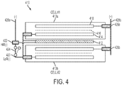
- Figure 4 illustrates such an embodiment.
- battery module 410 includes resistor sheet 412 positioned between two cells 413a and 413b.
- the resistor sheet is preferably positioned between the cells to provide even heating of the cells and battery module, such as interposed tightly between the two cells.
- Each cell includes anode electrodes 414, separators 416 and cathode electrodes 418.
- Battery module 410 further includes one low-resistance negative terminal LoR(-) 420 which is electrically connected to each cell of the module and one high-resistance negative terminal HiR(-) 422, which is electrically connected to the resistor sheet.
- the battery module also includes switch 424 and positive terminals (+) 426a and 426b. The negative and positive terminals can be electrically connected to an external circuit 428a and 428b.
- the rechargeable battery module 410 of Fig. 4 can be operated in the same manner as described for Fig. 1 .
- battery module 410 in Fig. 4 is illustrated as a twin-cell module with one resistor sheet between the two cells
- battery modules of the present disclosure can have more than two cells and/or more than one resistor sheets positioned in the middle of the cell modules.
- the battery module can have 4, 5 or 6 cells with one or more resistor sheets positioned between cells and around other positions near the cells.
- one or more of the resistor sheets shown in Fig. 3 can be used in the configurations of Fig. 4 .
- the tabs labeled as Tab 1 can be connected to the negative terminals of the cells, forming a low-resistance terminal for the battery module, LoR(-).
- Tab 2 of any of the resistor sheets shown in Fig. 3 can be welded together to form the high resistance terminal of the battery module, HiR(-). The activation and operation of such a battery module is the same as for a single cell described earlier.
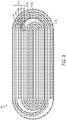
- one or more resistor sheets can be sandwiched between two jelly rolls of electrode-separator assembly of a rechargeable battery.
- Figure 5 illustrates such an embodiment.
- resistor sheet 512 is sandwiched between two jelly rolls (513a, 513b).
- the design in this embodiment can be used with any conventional rechargeable battery containing jelly roll electrode assemblies.
- the electrically resistor sheet 512 has two tabs (512a, 512b), which can be attached by welding.
- Resistor tab 512a is electrically connected to anode tabs 514a of anode electrodes of the jelly roll (not shown for illustrative convenience) and to a low-resistance negative terminal LoR(-) (not shown) to form a low electrical resistance circuit.
- Resistor tab 512b is electrically connected to high-resistance negative terminal HiR(-) (not shown) to form a high electrical resistance level circuit.
- Cathode tabs 518a of cathode electrodes of the jelly roll are electrically connected together and to a positive terminal (not shown for illustrative convenience).
- the rechargeable battery in this embodiment would also include a switch outside of the battery that can electrically connect or disconnect the LoR(-) terminal and the HiR(-) terminal.
- the rechargeable battery 510 of Fig. 5 can be operated in the same manner as described for Fig. 1 .
- rechargeable batteries of the present disclosure can have more than two jelly rolls and/or more than one resistor sheet positioned in the middle of the jelly roll.
- the one or more resistor sheets can be coated with a thin layer of a polymer or oxide to isolate it from an electrolyte within the battery.
- the battery can have three or more jelly rolls with one or more resistor sheets positioned between a pair of jelly rolls and/or around other positions near each or some of the jelly rolls.
- one or more of the resistor sheets shown in Fig. 3 can be used in the configurations of Fig. 5 .
- the tabs labeled as Tab 1 can be connected to the negative terminals of the cells, forming a low-resistance terminal for the battery, LoR(-).
- Tab 2 of any of the resistor sheets shown in Fig. 3 can be welded together to form the high resistance terminal of the battery, HiR(-). The activation and operation of such a battery is the same as described for the battery of Fig. 1 .
- a rechargeable battery can be constructed without using a separate resistor sheet to produce the high electrical internal resistance level of the battery.
- a high electrical resistance circuit can be configured to be integrally part of the current collector of an electrode of the cell of the battery.
- a rechargeable battery includes at least one negative terminal and at least one positive terminal for operating the battery at R 1 over T 1 and T 2 ; at least one high resistance terminal (e.g., an additional negative or positive terminal) for operating the battery at R 2 outside of either T 1 or T 2 ; and a switch that activates R 2 when the temperature of the battery is outside of either T 1 or T 2 , wherein the at least one high resistance terminal is electrically connected to at least one resistor sheet within a cell of the battery and wherein the at least one resistor sheet is integrally part of the current collector of an electrode of the cell of the battery.
- the at least one high resistance terminal is electrically connected to at least one resistor sheet within a cell of the battery and wherein the at least one resistor sheet is integrally part of the current collector of an electrode of the cell of the battery.
- FIG. 6 illustrates such an embodiment.
- Fig. 6 shows an assembly including anode electrode 614, separator 616 and cathode electrode 618.
- This assembly is applicable to a wide variety of rechargeable battery configurations, such as a jelly roll design in a cell casing.
- cathode (positive) electrode 618 includes a number of closely spaced tabs 618a electrically connected (e.g., welded together) to form Terminal (+) 626.
- anode (negative) electrode 614 includes a few closely spaced tabs (614a) electrically connected together to form terminal LoR(-) 620 and tab 614b that is at a distance from the closest tab 614a.
- Tab 614b can be electrically connected to a high electrical resistance terminal. In this example, Tab 614b forms the high electrical resistance terminal HiR(-).
- the material between tabs 614a and 614b acts as the resistor sheet for this battery design.
- the terminals LoR(-) and HiR(-) can be electrically connected and disconnected via switch 624, e.g., a temperature-sensitive switch. Activation and operation of a battery with the configuration illustrated in Fig. 6 can be done in the same manner as described for the battery in Fig. 1 .
- the electrical resistance of 630 will depend on, among other things, the distance between tab 614b and the closest tab 614a, on the material used to form the current collector, e.g., the composition of the foil, and any material on the foil between the two tabs and the desired resistance level of the high resistance terminal. Electrodes of a rechargeable battery are typically formed by coating one or more electrochemically active materials, with or without a binder and/or conductive diluent, onto a current collector. Such materials can also affect the electrical resistance of 630.
- Figure 7 illustrates another embodiment of a rechargeable battery of the present disclosure including a resistor sheet that is integrally part of the current collector of an electrode of the cell of the battery.
- an assembly including anode electrode 714, separator 716 and cathode electrode 718 are shown.
- the assembly shown in Fig. 7 is applicable to a wide variety of rechargeable battery configurations.
- both cathode and anode electrodes have a number of closely spaced tabs electrically connected to form Terminals LoR(+) and LoR(-) as well as far-away tabs to form HiR(+) and HiR(-).
- cathode (positive) electrode 718 includes a number of closely spaced tabs 718a electrically connected to form Terminal (+) 726 and tab 718b that is at a distance from the closest tab 718a to form the high electrical resistance terminal HiR(+).
- Anode (negative) electrode 714 includes a few closely spaced tabs (714a) electrically connected together to form terminal LoR(-) 720 and tab 714b that is at a distance from the closest tab 714a to form the high electrical resistance terminal HiR(-)
- the portions of the negative electrode foil (i.e. Cu) and positive electrode foil (i.e. Al) between the closely spaced tab group and far-away tab act as a large resistance to be operative when the battery temperature is below the normal range, i.e. below T 1 .
- the material between tabs 714a and 714b (designated 730a) and the material between tabs 718a and 718b (designated 730b) act as resistor sheets for this battery design.
- two independent switches (724a, 724b) can be used to connect the terminal LoR(+) with HiR(+) and LoR(-) with HiR(-), respectively.
- the two switches can operate simultaneously, or independently from each other, or according to an algorithm as a function of battery temperature. Otherwise, activation and operation of a battery with the configuration illustrated in Fig. 7 can be done in the same manner as described for the battery in Fig. 1 .
- one or more resistor sheets can be included with a rolled electrode assembly of a rechargeable battery.
- Figures 8 , 9 and 10 illustrate embodiments of a jelly rolled electrode assembly having one or more resistor sheets.
- resistor sheet 812 is included within about the center of the jelly roll assembly.
- the resistor does not directly contact any electrode and should not adversely affect the capacity of the cell.
- the resistor sheet can be inserted after the jelly roll is assembled or while assembling the jelly roll.
- the resistor sheet can also advantageously act as a structural support for the jelly roll assembly.
- the design in this embodiment can be used with any conventional rechargeable battery containing jelly roll electrode assemblies. As further shown in Fig.
- the jelly roll assembly 813 further includes anode electrode 814 on current collector 815, e.g., a copper foil, first separator 816a, cathode electrode 818 on current collector 819, e.g. an aluminum foil, and second separator 816b.
- anode electrode 814 on current collector 815 e.g., a copper foil
- first separator 816a e.g., a copper foil
- cathode electrode 818 on current collector 819 e.g. an aluminum foil
- second separator 816b e.g. an aluminum foil
- a resistor sheet can be included on the outermost layer of the jelly roll.
- the jelly roll can be flat in shape, as shown in Fig.8 , or cylindrical.
- Fig. 9 illustrates another embodiment of a jelly roll electrode assembly having a resistor sheet.
- a series of resistor sheets are wrapped around a series of jelly roll assemblies.
- resistor sheets 912a and 912b are wrapped around jelly roll assemblies 913a and 913b.
- Fig. 9 shows two jelly roll assemblies each having a resistor sheet on the outer circumference thereof. This configuration can be extended to additional jelly roll assemblies some or all of which have a resistor sheet on the outer circumference thereof to form a jelly roll assembly having a series of resistor sheets wrapped around a series of jelly roll assemblies.
- Such an assembly can be fabricated by winding a jelly roll assembly and then wrapping the resistor sheet on the outer circumference thereof followed by winding additional jelly roll assemblies with or without resistor sheets thereon.
- Each of the jelly roll assemblies includes an anode electrode, cathode electrode, and separator.
- jelly roll assemblies 913a and 913b include anode electrode 914 on current collector 915, e.g., a copper foil, first separator 916a, cathode electrode 918 on current collector 919, e.g. an aluminum foil.
- a second separator can be included after current collector 919, which is not shown in the figure.
- a resistor sheet can be included in more or less the center of the inner most jelly roll assembly.
- Fig. 10 illustrates another embodiment of a jelly roll electrode assembly having a resistor sheet.
- the container holding the jelly roll assembly or assemblies can act as the resistor sheet even though it is not in the shape of a sheet.
- resistor sheet 1012 surrounds two jelly roll assemblies 1013a and 1013b.
- Resistor sheet 1012 has an inner surface 1012a contact a substantial portion of the outermost layer of the jelly roll assemblies.
- the resistor sheet can be a container holding the assemblies, e.g., a steel can.
- resistor sheet 1012 is shaped to have two compartments to hold the two jelly roll assemblies but this embodiment is not limited to such a shape so long as an inner surface of resistor sheet 1012 contacts a substantial portion of at least one of the jelly roll assemblies, the resistor sheet can function as described in the present disclosure.
- the configuration of Fig. 10 can be extended to additional jelly roll assemblies some or all of which are positioned in one or more compartments or contact the resistor sheet.
- Each of the jelly roll assemblies includes an anode electrode, first separator, cathode electrode, and second separator.
- jelly roll assemblies 1013a and 1013b include anode electrode 1014 on current collector 1015, e.g., a copper foil, first separator 1016a, cathode electrode 1018 on current collector 1019, e.g. an aluminum foil.
- a second separator can be included after current collector 919, which is not shown in the figure.
- resistor sheet 1012 a resistor sheet can be included in more or less the center of one or all of the jelly roll assemblies in this embodiment.
- Figs. 8 , 9 , and 10 are illustrated as jelly rolls that having an asymmetrical shape, the jelly rolls and resistor sheets can be symmetrical, such as cylindrical jelly roll assemblies with corresponding cylindrical resistor sheets.
- Figs. 8 , 9 , 10 additional elements are included to form working batteries with the configurations of Figs. 8 , 9 and 10 , which were not shown for illustrative convenience.
- These elements include, for example, a high resistance terminal electrically connected to the resistor sheet as part of a high electrical resistance level circuit; a low resistance terminal which is electrically connected to the resistor sheet and to one of the electrodes, e.g., the anode or cathode electrodes, to form a low electrical resistance circuit; a switch that can electrically connect or disconnect the low resistance and high resistance terminals.
- the rechargeable battery 810, 910 and 1010 of Figs. 8 , 9 and 10 respectively, can be operated in the same manner as described for Fig. 1 , for example.
- one or more of the resistor sheets shown in Fig. 3 can be used in the configurations of Figs. 8 , 9 and 10 .
- the tabs labeled as Tab 1 can be connected to the negative terminals of the cells, forming a low-resistance terminal for the battery, LoR(-).
- Tab 2 of any of the resistor sheets shown in Fig. 3 can be welded together to form the high resistance terminal of the battery, HiR(-). The activation and operation of such a battery is the same as described for the battery of Fig. 1 .
- the rechargeable battery of the present disclosure can be implemented for all battery chemistries, such as rechargeable lithium ion, nickel-metal hydride, or advanced lithium batteries such as lithium-sulfur, lithium-polymer, lithium-air batteries or all solid-state batteries, and for all form factors, either pouch, cylindrical, prismatic or angular.
- the cell designs described above for Figs. 1-10 can be used to fabricate an all climate battery with a low internal resistance (R 1 ) for one set of terminals and a high internal resistance (R 2 ) for a second set of terminals.
- the cell structure can accommodate rolled electrode and stacked electrode designs, among other designs.
- a rechargeable battery is operated at R 1 when the temperature of the battery is between T 1 and T 2 , and at R 2 outside of either T 1 or T 2 by activating a switch that activates R 2 when the temperature of the battery is outside of either T 1 or T 2 .
- Operating the battery at a high resistance level (R 2 ) can include applying a constant voltage - constant current (CVCC) cycle to increase the internal temperature of the battery.
- CVCC constant voltage - constant current
- Such an activation cycle can generate a large amount of internal heat by operating the battery in the high-resistance mode and under a low cell voltage.
- the activation cycle can include operating the battery under constant voltage followed by constant current limit.
- the constant voltage is set in a range from 0.2 to 1V and the current limit is set in a range from 1C to 10C (C-rate defined here is a ratio of the current in Amps to the battery nominal capacity; say for a 10Ah battery, 1C means 10A).
- C-rate defined here is a ratio of the current in Amps to the battery nominal capacity; say for a 10Ah battery, 1C means 10A).
- the constant voltage ranges from 0.4V to 1.0V and the current limit is 2C to 5C, e.g. 4C.
- a pilot-production battery of 26Ah in the form of a pouch cell and made of lithium-nickel-manganese-cobalt (NMC) cathode and graphite anode, was developed according to the construction described in Fig.1 .
- the resistor sheet is a stainless steel foil of 25 cm long, 6 cm wide and 100 um thick. Its resistance is approximately 0.05 Ohm and its weight is -13 grams which is about 2.3% of the total battery weight.
- the switch between the LoR(-) and HiR(-) terminals is done by an electromechanical relay driven by a temperature controller. The relay is set to switch at about 0 °C. The relay weighs about 7 grams.
- test battery Prior to testing, the test battery is fully charged and then soaked for 5-6 hours in a thermal chamber that is preset at a subfreezing temperature.
- a thermal chamber that is preset at a subfreezing temperature.
- several thermocouples are mounted onto the battery and connected to voltmeters to read the average battery temperature which drives the relay.
- a baseline cell without the resistor foil and the temperature-sensitive switch but remaining otherwise identical was also tested for a comparative study.
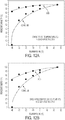
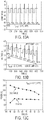
- the conventional LiB outputs only 60% and 50% of room-temperature capacity and energy at -30°C.
- the improvement of ACB performance at -40 °C is even more substantial, retaining 85% and 70% of room-temperature capacity and energy, whereas the conventional LiB has almost zero capacity and energy output under the same ambient condition. 2C discharge experiments have been also carried out, and power and energy output is equally impressive.
- HPPC hybrid power pulse characterization
Landscapes
- Chemical & Material Sciences (AREA)
- Chemical Kinetics & Catalysis (AREA)
- General Chemical & Material Sciences (AREA)
- Electrochemistry (AREA)
- Engineering & Computer Science (AREA)
- Manufacturing & Machinery (AREA)
- Materials Engineering (AREA)
- Physics & Mathematics (AREA)
- Electromagnetism (AREA)
- Automation & Control Theory (AREA)
- Secondary Cells (AREA)
- Connection Of Batteries Or Terminals (AREA)
- Cell Electrode Carriers And Collectors (AREA)
- Battery Electrode And Active Subsutance (AREA)
Priority Applications (1)
| Application Number | Priority Date | Filing Date | Title |
|---|---|---|---|
| PL14877290T PL3055899T3 (pl) | 2013-10-11 | 2014-10-08 | Akumulator do każdych warunków klimatycznych i jego wytwarzanie oraz stosowanie |
Applications Claiming Priority (3)
| Application Number | Priority Date | Filing Date | Title |
|---|---|---|---|
| US201361890012P | 2013-10-11 | 2013-10-11 | |
| US14/255,780 US9882197B2 (en) | 2013-10-11 | 2014-04-17 | All climate battery and manufacturing and using the same |
| PCT/US2014/059726 WO2015102708A2 (en) | 2013-10-11 | 2014-10-08 | All climate battery and manufacturing and using same |
Publications (3)
| Publication Number | Publication Date |
|---|---|
| EP3055899A2 EP3055899A2 (en) | 2016-08-17 |
| EP3055899A4 EP3055899A4 (en) | 2017-04-19 |
| EP3055899B1 true EP3055899B1 (en) | 2019-01-02 |
Family
ID=53494191
Family Applications (1)
| Application Number | Title | Priority Date | Filing Date |
|---|---|---|---|
| EP14877290.8A Active EP3055899B1 (en) | 2013-10-11 | 2014-10-08 | All climate battery and manufacturing and using same |
Country Status (9)
| Country | Link |
|---|---|
| US (1) | US9882197B2 (https=) |
| EP (1) | EP3055899B1 (https=) |
| JP (1) | JP6581974B2 (https=) |
| KR (1) | KR101979071B1 (https=) |
| CN (1) | CN105849968B (https=) |
| ES (1) | ES2710780T3 (https=) |
| HU (1) | HUE043148T2 (https=) |
| PL (1) | PL3055899T3 (https=) |
| WO (1) | WO2015102708A2 (https=) |
Families Citing this family (43)
| Publication number | Priority date | Publication date | Assignee | Title |
|---|---|---|---|---|
| US9502708B2 (en) | 2013-10-11 | 2016-11-22 | Ec Power, Llc | Ohmically modulated battery |
| US10033071B2 (en) | 2013-10-11 | 2018-07-24 | Ec Power, Llc | Ohmically modulated battery |
| WO2016018830A1 (en) | 2014-07-28 | 2016-02-04 | Ec Power, Llc | Systems and methods for fast charging batteries at low temperatures |
| KR102546297B1 (ko) | 2014-12-01 | 2023-06-21 | 이씨 파워, 엘엘씨 | 완전 고체 상태 리튬 배터리 |
| WO2016118740A1 (en) | 2015-01-21 | 2016-07-28 | Ec Power, Llc | Self-heating fuel cell systems |
| US10431858B2 (en) | 2015-02-04 | 2019-10-01 | Global Web Horizons, Llc | Systems, structures and materials for electrochemical device thermal management |
| KR20160097677A (ko) * | 2015-02-09 | 2016-08-18 | 삼성에스디아이 주식회사 | 리튬 이차 전지용 음극 활물질 및 이를 포함하는 리튬 이차 전지 |
| JP2019514002A (ja) | 2016-04-15 | 2019-05-30 | プレジデント アンド フェローズ オブ ハーバード カレッジ | 液滴および/または他の実体の収集のためのシステムおよび方法 |
| KR102589287B1 (ko) | 2017-01-19 | 2023-10-13 | 내션얼 리서치 카운슬 오브 캐나다 | 배터리에서 열폭주를 개시하기 위한 장치 및 방법 |
| CN106684458B (zh) * | 2017-01-22 | 2019-09-17 | 湖南立方新能源科技有限责任公司 | 一种改善低温充放电性能的锂离子电池及其制备方法 |
| JP2018147704A (ja) * | 2017-03-06 | 2018-09-20 | マツダ株式会社 | リチウムイオン電池構造 |
| CN110402519A (zh) * | 2017-03-22 | 2019-11-01 | 通用汽车环球科技运作有限责任公司 | 自动加热蓄电池 |
| USD911961S1 (en) | 2017-04-03 | 2021-03-02 | Latent Heat Solutions, Llc | Battery container |
| EP3413393A1 (en) * | 2017-06-07 | 2018-12-12 | Robert Bosch GmbH | Electrode assembly for a battery module |
| CN107275895A (zh) * | 2017-06-13 | 2017-10-20 | 安顺云首创科技开发有限公司 | 一种自动切换电阻连接器 |
| DE102017211001A1 (de) | 2017-06-29 | 2019-01-03 | Robert Bosch Gmbh | Hybrides Batteriesystem und Verfahren zum Betrieb eines hybriden Batteriesystems |
| US11367910B2 (en) | 2018-04-16 | 2022-06-21 | Ec Power, Llc | Systems and method of battery charging assisted by heating |
| JP7014030B2 (ja) * | 2018-04-20 | 2022-02-01 | マツダ株式会社 | 車両用蓄電装置 |
| DE102018209461A1 (de) * | 2018-06-13 | 2019-12-19 | Bayerische Motoren Werke Aktiengesellschaft | Verfahren zum impedanzgesteuerten Schnellladen, Steuereinheit für ein Ladesystem, Energiespeicher und Arbeitsvorrichtung |
| DE102018210660B4 (de) | 2018-06-28 | 2025-08-28 | Bayerische Motoren Werke Aktiengesellschaft | Speicherzelle für einen Energiespeicher eines Kraftfahrzeugs sowie Energiespeicher für ein Kraftfahrzeug |
| CN109244598B (zh) * | 2018-10-30 | 2021-06-01 | 江苏塔菲尔新能源科技股份有限公司 | 一种具有快速加热功能的复合正极极片、及采用其的电芯和电池 |
| CN109244599B (zh) * | 2018-10-30 | 2021-09-21 | 宁德时代新能源科技股份有限公司 | 一种具有快速加热功能的复合负极极片、及采用其的电芯和电池 |
| CN109378556B (zh) * | 2018-10-30 | 2021-07-02 | 江苏塔菲尔新能源科技股份有限公司 | 一种具有快速加热功能的热阻复合箔材、及采用其的电芯和电池 |
| CN109755656B (zh) * | 2019-01-14 | 2022-03-22 | 西北工业大学 | 一种新型“自激活式”锂离子二次贮备电池及其制备方法 |
| US20200259232A1 (en) * | 2019-02-13 | 2020-08-13 | Ec Power, Llc | Stable battery with high performance on demand |
| US11444339B2 (en) | 2019-07-23 | 2022-09-13 | Global Graphene Group, Inc. | Battery fast-charging system and method of operating same |
| US11502341B2 (en) | 2019-07-24 | 2022-11-15 | Global Graphene Group, Inc. | Battery fast-charging and cooling system and method of operating same |
| CN113514772B (zh) * | 2020-04-10 | 2024-08-23 | 广汽埃安新能源汽车有限公司 | 一种电池直流内阻在线测试方法及电池管理系统 |
| CN113594637A (zh) | 2020-04-30 | 2021-11-02 | 宁德时代新能源科技股份有限公司 | 电池模组、装置、电池包以及电池模组的制造方法和设备 |
| CN114342173B (zh) | 2020-07-29 | 2023-12-22 | 宁德时代新能源科技股份有限公司 | 电池模组、电池包、装置以及电池模组的制造方法和制造设备 |
| CN119864587B (zh) | 2020-09-30 | 2025-10-14 | 宁德时代新能源科技股份有限公司 | 电池、装置、电池的制备方法以及制备装置 |
| JP7466656B2 (ja) | 2020-09-30 | 2024-04-12 | 寧徳時代新能源科技股▲分▼有限公司 | 電池、装置、電池の製造方法及び製造装置 |
| EP4064436A4 (en) | 2020-09-30 | 2023-05-03 | Contemporary Amperex Technology Co., Limited | BATTERY, DEVICE AND METHOD OF MANUFACTURE AND DEVICE FOR A BATTERY |
| CN112151851B (zh) * | 2020-10-30 | 2022-03-29 | 珠海冠宇电池股份有限公司 | 一种能够降低内部温升的叠片式锂离子电池用叠芯 |
| EP4064421A4 (en) | 2020-11-17 | 2023-09-13 | Contemporary Amperex Technology Co., Limited | BATTERY, DEVICE USING BATTERY, AND METHOD AND DEVICE FOR PREPARING BATTERY |
| CN112670622A (zh) * | 2020-12-22 | 2021-04-16 | 山东大学 | 一种基于恒流恒压充放电的低温锂离子电池交流预热方法 |
| WO2022133959A1 (zh) | 2020-12-24 | 2022-06-30 | 宁德时代新能源科技股份有限公司 | 电池模组及其制造方法和设备、电池包及用电装置 |
| CN113437351B (zh) * | 2021-06-22 | 2023-01-24 | 宁德新能源科技有限公司 | 电化学装置及包括该电化学装置的用电设备 |
| CN116438697A (zh) * | 2021-07-30 | 2023-07-14 | 宁德时代新能源科技股份有限公司 | 一种电池组、电池包和用电装置 |
| DE102021004055A1 (de) * | 2021-08-05 | 2021-12-02 | Daimler Ag | Verfahren zum Heizen einer Batterie und Batterie |
| KR20230071656A (ko) | 2021-11-16 | 2023-05-23 | 주식회사 엘지에너지솔루션 | 이차 전지 및 감지 시스템 |
| WO2023147701A1 (zh) * | 2022-02-07 | 2023-08-10 | 宁德新能源科技有限公司 | 电化学装置及用电装置 |
| DE102024002164A1 (de) | 2024-07-03 | 2026-01-08 | Mercedes-Benz Group AG | Batteriemodul, Batterie und Fahrzeug |
Family Cites Families (31)
| Publication number | Priority date | Publication date | Assignee | Title |
|---|---|---|---|---|
| JPS5718402B2 (https=) * | 1973-11-28 | 1982-04-16 | ||
| JPS63205049A (ja) * | 1987-02-20 | 1988-08-24 | Shin Kobe Electric Mach Co Ltd | リチウム電池 |
| JPH0992335A (ja) | 1995-09-27 | 1997-04-04 | Sony Corp | 円筒形二次電池 |
| JPH11162310A (ja) * | 1997-11-28 | 1999-06-18 | Alps Electric Co Ltd | 熱応動スイッチ及びこの熱応動スイッチを用いた電気機器 |
| WO1999067836A1 (fr) | 1998-06-25 | 1999-12-29 | Mitsubishi Denki Kabushiki Kaisha | Cellule et procede de production |
| US6072301A (en) | 1998-10-20 | 2000-06-06 | Chrysler Corporation | Efficient resonant self-heating battery electric circuit |
| JP2001035641A (ja) * | 1999-07-23 | 2001-02-09 | Nok Corp | 面状発熱体 |
| JP2001319636A (ja) * | 2000-05-11 | 2001-11-16 | Japan Storage Battery Co Ltd | 非水電解質二次電池 |
| JP2002125326A (ja) | 2000-10-12 | 2002-04-26 | Honda Motor Co Ltd | バッテリの充電制御方法 |
| KR100470287B1 (ko) * | 2000-12-28 | 2005-02-05 | 마쯔시다덴기산교 가부시키가이샤 | 비수전해질(非水電解質) 이차전지 |
| JP2002369402A (ja) | 2001-06-04 | 2002-12-20 | Toyota Motor Corp | 充電制御装置 |
| JP2005285624A (ja) * | 2004-03-30 | 2005-10-13 | Sanyo Electric Co Ltd | 自己復帰型安全機構付き二次電池 |
| KR100786941B1 (ko) * | 2005-05-10 | 2007-12-17 | 주식회사 엘지화학 | 이차전지 보호회로 및 이를 구비한 이차전지 |
| DE102007029744A1 (de) | 2007-06-27 | 2009-01-08 | Robert Bosch Gmbh | Anordnung mit wenigstens einer Batterie |
| JP5314872B2 (ja) | 2007-10-01 | 2013-10-16 | 株式会社オハラ | 発熱機構を備える二次電池 |
| JP5169715B2 (ja) | 2007-10-17 | 2013-03-27 | 株式会社デンソー | 車両用蓄電手段の加熱装置 |
| JP5315742B2 (ja) * | 2008-03-25 | 2013-10-16 | 株式会社Gsユアサ | 電池 |
| JP2010067386A (ja) * | 2008-09-09 | 2010-03-25 | Toyota Motor Corp | 蓄電素子の昇温構造及び蓄電装置 |
| JP5359390B2 (ja) * | 2009-03-06 | 2013-12-04 | トヨタ自動車株式会社 | 電池温度調節装置 |
| US9431688B2 (en) * | 2010-05-21 | 2016-08-30 | GM Global Technology Operations LLC | Method for heating a high voltage vehicle battery |
| US8334675B2 (en) | 2010-07-28 | 2012-12-18 | Honda Motor Co., Ltd. | Method of charging battery based on calcualtion of an ion concentration of a solid active material and battery charging control system |
| CN102074762B (zh) | 2010-07-30 | 2012-07-04 | 比亚迪股份有限公司 | 一种电池的加热电路 |
| JP5617473B2 (ja) | 2010-09-21 | 2014-11-05 | 株式会社デンソー | 電池加熱装置 |
| JP2012069496A (ja) | 2010-09-27 | 2012-04-05 | Denso Corp | 電池加熱装置 |
| US9252402B2 (en) * | 2011-02-02 | 2016-02-02 | Gs Yuasa International Ltd. | Battery system |
| JP5708070B2 (ja) | 2011-03-11 | 2015-04-30 | 日産自動車株式会社 | バッテリ温度制御装置 |
| WO2012169063A1 (ja) * | 2011-06-10 | 2012-12-13 | 日立ビークルエナジー株式会社 | 電池制御装置、電池システム |
| DE102012210146A1 (de) | 2012-06-15 | 2013-12-19 | Robert Bosch Gmbh | Vorrichtung und Verfahren zum Heizen einer Batterie, Batterie und Kraftfahrzeug mit Batterie |
| JP5842759B2 (ja) * | 2012-07-30 | 2016-01-13 | 株式会社豊田自動織機 | 温度推定方法及び温度推定装置 |
| US9502708B2 (en) * | 2013-10-11 | 2016-11-22 | Ec Power, Llc | Ohmically modulated battery |
| US9627723B2 (en) * | 2014-07-30 | 2017-04-18 | Ec Power, Llc | Operation of electrochemical energy systems |
-
2014
- 2014-04-17 US US14/255,780 patent/US9882197B2/en active Active
- 2014-10-08 HU HUE14877290A patent/HUE043148T2/hu unknown
- 2014-10-08 PL PL14877290T patent/PL3055899T3/pl unknown
- 2014-10-08 JP JP2016521719A patent/JP6581974B2/ja active Active
- 2014-10-08 KR KR1020167010745A patent/KR101979071B1/ko active Active
- 2014-10-08 ES ES14877290T patent/ES2710780T3/es active Active
- 2014-10-08 WO PCT/US2014/059726 patent/WO2015102708A2/en not_active Ceased
- 2014-10-08 EP EP14877290.8A patent/EP3055899B1/en active Active
- 2014-10-08 CN CN201480055954.0A patent/CN105849968B/zh active Active
Non-Patent Citations (1)
| Title |
|---|
| None * |
Also Published As
| Publication number | Publication date |
|---|---|
| KR20160070767A (ko) | 2016-06-20 |
| EP3055899A2 (en) | 2016-08-17 |
| JP6581974B2 (ja) | 2019-09-25 |
| WO2015102708A2 (en) | 2015-07-09 |
| PL3055899T3 (pl) | 2019-06-28 |
| US9882197B2 (en) | 2018-01-30 |
| EP3055899A4 (en) | 2017-04-19 |
| WO2015102708A3 (en) | 2015-08-20 |
| KR101979071B1 (ko) | 2019-05-15 |
| JP2016538683A (ja) | 2016-12-08 |
| HUE043148T2 (hu) | 2019-08-28 |
| US20150303444A1 (en) | 2015-10-22 |
| CN105849968B (zh) | 2019-05-21 |
| CN105849968A (zh) | 2016-08-10 |
| ES2710780T3 (es) | 2019-04-26 |
Similar Documents
| Publication | Publication Date | Title |
|---|---|---|
| EP3055899B1 (en) | All climate battery and manufacturing and using same | |
| EP3055898B1 (en) | Ohmically modulated battery | |
| US10033071B2 (en) | Ohmically modulated battery | |
| CA2911485C (en) | Rechargeable battery with multiple resistance levels | |
| KR102213020B1 (ko) | 저온에서 배터리를 고속으로 충전하는 시스템 및 방법 | |
| JP3799463B2 (ja) | 電池モジュール | |
| US20200235444A1 (en) | Self-heating battery | |
| KR20170091133A (ko) | 완전 고체 상태 리튬 배터리 | |
| KR20130089376A (ko) | 온도 센서를 포함하는 이차전지 | |
| KR20140089455A (ko) | 이차전지 어셈블리 |
Legal Events
| Date | Code | Title | Description |
|---|---|---|---|
| PUAI | Public reference made under article 153(3) epc to a published international application that has entered the european phase |
Free format text: ORIGINAL CODE: 0009012 |
|
| 17P | Request for examination filed |
Effective date: 20160511 |
|
| AK | Designated contracting states |
Kind code of ref document: A2 Designated state(s): AL AT BE BG CH CY CZ DE DK EE ES FI FR GB GR HR HU IE IS IT LI LT LU LV MC MK MT NL NO PL PT RO RS SE SI SK SM TR |
|
| AX | Request for extension of the european patent |
Extension state: BA ME |
|
| DAX | Request for extension of the european patent (deleted) | ||
| RIC1 | Information provided on ipc code assigned before grant |
Ipc: H01M 10/30 20060101ALN20170301BHEP Ipc: H01M 10/48 20060101ALI20170301BHEP Ipc: H01M 10/36 20100101AFI20170301BHEP Ipc: H01M 10/6571 20140101ALI20170301BHEP Ipc: H01M 2/30 20060101ALN20170301BHEP Ipc: H01M 10/0525 20100101ALN20170301BHEP Ipc: H01M 10/44 20060101ALI20170301BHEP Ipc: H01M 2/10 20060101ALI20170301BHEP Ipc: H01M 10/63 20140101ALI20170301BHEP |
|
| A4 | Supplementary search report drawn up and despatched |
Effective date: 20170309 |
|
| RA4 | Supplementary search report drawn up and despatched (corrected) |
Effective date: 20170317 |
|
| STAA | Information on the status of an ep patent application or granted ep patent |
Free format text: STATUS: EXAMINATION IS IN PROGRESS |
|
| 17Q | First examination report despatched |
Effective date: 20180409 |
|
| GRAP | Despatch of communication of intention to grant a patent |
Free format text: ORIGINAL CODE: EPIDOSNIGR1 |
|
| STAA | Information on the status of an ep patent application or granted ep patent |
Free format text: STATUS: GRANT OF PATENT IS INTENDED |
|
| RIC1 | Information provided on ipc code assigned before grant |
Ipc: H01M 10/63 20140101ALI20180522BHEP Ipc: H01M 10/6571 20140101ALI20180522BHEP Ipc: H01M 10/30 20060101ALN20180522BHEP Ipc: H01M 2/30 20060101ALN20180522BHEP Ipc: H01M 10/44 20060101ALI20180522BHEP Ipc: H01M 10/36 20100101AFI20180522BHEP Ipc: H01M 2/10 20060101ALI20180522BHEP Ipc: H01M 10/48 20060101ALI20180522BHEP Ipc: H01M 10/0525 20100101ALN20180522BHEP |
|
| INTG | Intention to grant announced |
Effective date: 20180607 |
|
| GRAS | Grant fee paid |
Free format text: ORIGINAL CODE: EPIDOSNIGR3 |
|
| GRAJ | Information related to disapproval of communication of intention to grant by the applicant or resumption of examination proceedings by the epo deleted |
Free format text: ORIGINAL CODE: EPIDOSDIGR1 |
|
| GRAL | Information related to payment of fee for publishing/printing deleted |
Free format text: ORIGINAL CODE: EPIDOSDIGR3 |
|
| STAA | Information on the status of an ep patent application or granted ep patent |
Free format text: STATUS: EXAMINATION IS IN PROGRESS |
|
| INTC | Intention to grant announced (deleted) | ||
| GRAR | Information related to intention to grant a patent recorded |
Free format text: ORIGINAL CODE: EPIDOSNIGR71 |
|
| STAA | Information on the status of an ep patent application or granted ep patent |
Free format text: STATUS: GRANT OF PATENT IS INTENDED |
|
| GRAA | (expected) grant |
Free format text: ORIGINAL CODE: 0009210 |
|
| STAA | Information on the status of an ep patent application or granted ep patent |
Free format text: STATUS: THE PATENT HAS BEEN GRANTED |
|
| RIC1 | Information provided on ipc code assigned before grant |
Ipc: H01M 10/44 20060101ALI20181029BHEP Ipc: H01M 10/48 20060101ALI20181029BHEP Ipc: H01M 10/63 20140101ALI20181029BHEP Ipc: H01M 10/30 20060101ALN20181029BHEP Ipc: H01M 10/36 20100101AFI20181029BHEP Ipc: H01M 10/0525 20100101ALN20181029BHEP Ipc: H01M 2/30 20060101ALN20181029BHEP Ipc: H01M 2/10 20060101ALI20181029BHEP Ipc: H01M 10/6571 20140101ALI20181029BHEP |
|
| INTG | Intention to grant announced |
Effective date: 20181120 |
|
| AK | Designated contracting states |
Kind code of ref document: B1 Designated state(s): AL AT BE BG CH CY CZ DE DK EE ES FI FR GB GR HR HU IE IS IT LI LT LU LV MC MK MT NL NO PL PT RO RS SE SI SK SM TR |
|
| REG | Reference to a national code |
Ref country code: GB Ref legal event code: FG4D |
|
| REG | Reference to a national code |
Ref country code: CH Ref legal event code: EP Ref country code: AT Ref legal event code: REF Ref document number: 1085567 Country of ref document: AT Kind code of ref document: T Effective date: 20190115 |
|
| REG | Reference to a national code |
Ref country code: IE Ref legal event code: FG4D |
|
| REG | Reference to a national code |
Ref country code: DE Ref legal event code: R096 Ref document number: 602014039368 Country of ref document: DE |
|
| REG | Reference to a national code |
Ref country code: NL Ref legal event code: FP |
|
| REG | Reference to a national code |
Ref country code: SE Ref legal event code: TRGR |
|
| REG | Reference to a national code |
Ref country code: ES Ref legal event code: FG2A Ref document number: 2710780 Country of ref document: ES Kind code of ref document: T3 Effective date: 20190426 |
|
| REG | Reference to a national code |
Ref country code: NO Ref legal event code: T2 Effective date: 20190102 |
|
| REG | Reference to a national code |
Ref country code: LT Ref legal event code: MG4D |
|
| REG | Reference to a national code |
Ref country code: AT Ref legal event code: MK05 Ref document number: 1085567 Country of ref document: AT Kind code of ref document: T Effective date: 20190102 |
|
| PG25 | Lapsed in a contracting state [announced via postgrant information from national office to epo] |
Ref country code: FI Free format text: LAPSE BECAUSE OF FAILURE TO SUBMIT A TRANSLATION OF THE DESCRIPTION OR TO PAY THE FEE WITHIN THE PRESCRIBED TIME-LIMIT Effective date: 20190102 Ref country code: PT Free format text: LAPSE BECAUSE OF FAILURE TO SUBMIT A TRANSLATION OF THE DESCRIPTION OR TO PAY THE FEE WITHIN THE PRESCRIBED TIME-LIMIT Effective date: 20190502 Ref country code: LT Free format text: LAPSE BECAUSE OF FAILURE TO SUBMIT A TRANSLATION OF THE DESCRIPTION OR TO PAY THE FEE WITHIN THE PRESCRIBED TIME-LIMIT Effective date: 20190102 |
|
| REG | Reference to a national code |
Ref country code: HU Ref legal event code: AG4A Ref document number: E043148 Country of ref document: HU |
|
| PG25 | Lapsed in a contracting state [announced via postgrant information from national office to epo] |
Ref country code: GR Free format text: LAPSE BECAUSE OF FAILURE TO SUBMIT A TRANSLATION OF THE DESCRIPTION OR TO PAY THE FEE WITHIN THE PRESCRIBED TIME-LIMIT Effective date: 20190403 Ref country code: HR Free format text: LAPSE BECAUSE OF FAILURE TO SUBMIT A TRANSLATION OF THE DESCRIPTION OR TO PAY THE FEE WITHIN THE PRESCRIBED TIME-LIMIT Effective date: 20190102 Ref country code: IS Free format text: LAPSE BECAUSE OF FAILURE TO SUBMIT A TRANSLATION OF THE DESCRIPTION OR TO PAY THE FEE WITHIN THE PRESCRIBED TIME-LIMIT Effective date: 20190502 Ref country code: BG Free format text: LAPSE BECAUSE OF FAILURE TO SUBMIT A TRANSLATION OF THE DESCRIPTION OR TO PAY THE FEE WITHIN THE PRESCRIBED TIME-LIMIT Effective date: 20190402 Ref country code: LV Free format text: LAPSE BECAUSE OF FAILURE TO SUBMIT A TRANSLATION OF THE DESCRIPTION OR TO PAY THE FEE WITHIN THE PRESCRIBED TIME-LIMIT Effective date: 20190102 Ref country code: RS Free format text: LAPSE BECAUSE OF FAILURE TO SUBMIT A TRANSLATION OF THE DESCRIPTION OR TO PAY THE FEE WITHIN THE PRESCRIBED TIME-LIMIT Effective date: 20190102 |
|
| REG | Reference to a national code |
Ref country code: DE Ref legal event code: R097 Ref document number: 602014039368 Country of ref document: DE |
|
| PG25 | Lapsed in a contracting state [announced via postgrant information from national office to epo] |
Ref country code: SK Free format text: LAPSE BECAUSE OF FAILURE TO SUBMIT A TRANSLATION OF THE DESCRIPTION OR TO PAY THE FEE WITHIN THE PRESCRIBED TIME-LIMIT Effective date: 20190102 Ref country code: RO Free format text: LAPSE BECAUSE OF FAILURE TO SUBMIT A TRANSLATION OF THE DESCRIPTION OR TO PAY THE FEE WITHIN THE PRESCRIBED TIME-LIMIT Effective date: 20190102 Ref country code: DK Free format text: LAPSE BECAUSE OF FAILURE TO SUBMIT A TRANSLATION OF THE DESCRIPTION OR TO PAY THE FEE WITHIN THE PRESCRIBED TIME-LIMIT Effective date: 20190102 Ref country code: AT Free format text: LAPSE BECAUSE OF FAILURE TO SUBMIT A TRANSLATION OF THE DESCRIPTION OR TO PAY THE FEE WITHIN THE PRESCRIBED TIME-LIMIT Effective date: 20190102 Ref country code: EE Free format text: LAPSE BECAUSE OF FAILURE TO SUBMIT A TRANSLATION OF THE DESCRIPTION OR TO PAY THE FEE WITHIN THE PRESCRIBED TIME-LIMIT Effective date: 20190102 Ref country code: AL Free format text: LAPSE BECAUSE OF FAILURE TO SUBMIT A TRANSLATION OF THE DESCRIPTION OR TO PAY THE FEE WITHIN THE PRESCRIBED TIME-LIMIT Effective date: 20190102 |
|
| PLBE | No opposition filed within time limit |
Free format text: ORIGINAL CODE: 0009261 |
|
| STAA | Information on the status of an ep patent application or granted ep patent |
Free format text: STATUS: NO OPPOSITION FILED WITHIN TIME LIMIT |
|
| PG25 | Lapsed in a contracting state [announced via postgrant information from national office to epo] |
Ref country code: SM Free format text: LAPSE BECAUSE OF FAILURE TO SUBMIT A TRANSLATION OF THE DESCRIPTION OR TO PAY THE FEE WITHIN THE PRESCRIBED TIME-LIMIT Effective date: 20190102 |
|
| 26N | No opposition filed |
Effective date: 20191003 |
|
| PG25 | Lapsed in a contracting state [announced via postgrant information from national office to epo] |
Ref country code: SI Free format text: LAPSE BECAUSE OF FAILURE TO SUBMIT A TRANSLATION OF THE DESCRIPTION OR TO PAY THE FEE WITHIN THE PRESCRIBED TIME-LIMIT Effective date: 20190102 |
|
| PG25 | Lapsed in a contracting state [announced via postgrant information from national office to epo] |
Ref country code: TR Free format text: LAPSE BECAUSE OF FAILURE TO SUBMIT A TRANSLATION OF THE DESCRIPTION OR TO PAY THE FEE WITHIN THE PRESCRIBED TIME-LIMIT Effective date: 20190102 |
|
| PG25 | Lapsed in a contracting state [announced via postgrant information from national office to epo] |
Ref country code: MC Free format text: LAPSE BECAUSE OF FAILURE TO SUBMIT A TRANSLATION OF THE DESCRIPTION OR TO PAY THE FEE WITHIN THE PRESCRIBED TIME-LIMIT Effective date: 20190102 |
|
| REG | Reference to a national code |
Ref country code: CH Ref legal event code: PL |
|
| PG25 | Lapsed in a contracting state [announced via postgrant information from national office to epo] |
Ref country code: LI Free format text: LAPSE BECAUSE OF NON-PAYMENT OF DUE FEES Effective date: 20191031 Ref country code: LU Free format text: LAPSE BECAUSE OF NON-PAYMENT OF DUE FEES Effective date: 20191008 Ref country code: CH Free format text: LAPSE BECAUSE OF NON-PAYMENT OF DUE FEES Effective date: 20191031 |
|
| PG25 | Lapsed in a contracting state [announced via postgrant information from national office to epo] |
Ref country code: IE Free format text: LAPSE BECAUSE OF NON-PAYMENT OF DUE FEES Effective date: 20191008 |
|
| PG25 | Lapsed in a contracting state [announced via postgrant information from national office to epo] |
Ref country code: CY Free format text: LAPSE BECAUSE OF FAILURE TO SUBMIT A TRANSLATION OF THE DESCRIPTION OR TO PAY THE FEE WITHIN THE PRESCRIBED TIME-LIMIT Effective date: 20190102 |
|
| PG25 | Lapsed in a contracting state [announced via postgrant information from national office to epo] |
Ref country code: MT Free format text: LAPSE BECAUSE OF FAILURE TO SUBMIT A TRANSLATION OF THE DESCRIPTION OR TO PAY THE FEE WITHIN THE PRESCRIBED TIME-LIMIT Effective date: 20190102 |
|
| REG | Reference to a national code |
Ref country code: DE Ref legal event code: R082 Ref document number: 602014039368 Country of ref document: DE Representative=s name: DOMPATENT VON KREISLER SELTING WERNER - PARTNE, DE Ref country code: DE Ref legal event code: R082 Ref document number: 602014039368 Country of ref document: DE Representative=s name: DOMPATENT - PARTNERSCHAFT VON PATENTANWAELTEN , DE |
|
| PG25 | Lapsed in a contracting state [announced via postgrant information from national office to epo] |
Ref country code: MK Free format text: LAPSE BECAUSE OF FAILURE TO SUBMIT A TRANSLATION OF THE DESCRIPTION OR TO PAY THE FEE WITHIN THE PRESCRIBED TIME-LIMIT Effective date: 20190102 |
|
| P01 | Opt-out of the competence of the unified patent court (upc) registered |
Effective date: 20230502 |
|
| PGFP | Annual fee paid to national office [announced via postgrant information from national office to epo] |
Ref country code: PL Payment date: 20250923 Year of fee payment: 12 |
|
| PGFP | Annual fee paid to national office [announced via postgrant information from national office to epo] |
Ref country code: CZ Payment date: 20250924 Year of fee payment: 12 |
|
| PGFP | Annual fee paid to national office [announced via postgrant information from national office to epo] |
Ref country code: HU Payment date: 20250923 Year of fee payment: 12 |
|
| PGFP | Annual fee paid to national office [announced via postgrant information from national office to epo] |
Ref country code: NL Payment date: 20251026 Year of fee payment: 12 |
|
| PGFP | Annual fee paid to national office [announced via postgrant information from national office to epo] |
Ref country code: DE Payment date: 20251029 Year of fee payment: 12 |
|
| PGFP | Annual fee paid to national office [announced via postgrant information from national office to epo] |
Ref country code: GB Payment date: 20251027 Year of fee payment: 12 |
|
| PGFP | Annual fee paid to national office [announced via postgrant information from national office to epo] |
Ref country code: NO Payment date: 20251029 Year of fee payment: 12 |
|
| PGFP | Annual fee paid to national office [announced via postgrant information from national office to epo] |
Ref country code: IT Payment date: 20251021 Year of fee payment: 12 |
|
| PGFP | Annual fee paid to national office [announced via postgrant information from national office to epo] |
Ref country code: FR Payment date: 20251027 Year of fee payment: 12 |
|
| PGFP | Annual fee paid to national office [announced via postgrant information from national office to epo] |
Ref country code: BE Payment date: 20251027 Year of fee payment: 12 |
|
| PGFP | Annual fee paid to national office [announced via postgrant information from national office to epo] |
Ref country code: SE Payment date: 20251027 Year of fee payment: 12 |
|
| PGFP | Annual fee paid to national office [announced via postgrant information from national office to epo] |
Ref country code: ES Payment date: 20251103 Year of fee payment: 12 |