EP3054154A1 - Structure material, wind power generation equipment, and wind power generation system - Google Patents
Structure material, wind power generation equipment, and wind power generation system Download PDFInfo
- Publication number
- EP3054154A1 EP3054154A1 EP16154296.4A EP16154296A EP3054154A1 EP 3054154 A1 EP3054154 A1 EP 3054154A1 EP 16154296 A EP16154296 A EP 16154296A EP 3054154 A1 EP3054154 A1 EP 3054154A1
- Authority
- EP
- European Patent Office
- Prior art keywords
- protection layer
- power generation
- wind power
- structure material
- layer
- Prior art date
- Legal status (The legal status is an assumption and is not a legal conclusion. Google has not performed a legal analysis and makes no representation as to the accuracy of the status listed.)
- Withdrawn
Links
- 239000000463 material Substances 0.000 title claims abstract description 112
- 238000010248 power generation Methods 0.000 title claims description 85
- 239000000758 substrate Substances 0.000 claims abstract description 58
- 238000012545 processing Methods 0.000 claims description 23
- 238000000034 method Methods 0.000 claims description 12
- 238000004891 communication Methods 0.000 claims description 7
- 238000009826 distribution Methods 0.000 claims description 3
- 230000008569 process Effects 0.000 claims description 2
- 230000008439 repair process Effects 0.000 description 18
- 239000005084 Strontium aluminate Substances 0.000 description 14
- 238000012544 monitoring process Methods 0.000 description 11
- 239000005083 Zinc sulfide Substances 0.000 description 10
- 229920005749 polyurethane resin Polymers 0.000 description 10
- 229910052761 rare earth metal Inorganic materials 0.000 description 10
- 229920003002 synthetic resin Polymers 0.000 description 10
- 229910052984 zinc sulfide Inorganic materials 0.000 description 10
- 230000007547 defect Effects 0.000 description 9
- 230000005283 ground state Effects 0.000 description 8
- 229920005989 resin Polymers 0.000 description 8
- 239000011347 resin Substances 0.000 description 8
- 230000000694 effects Effects 0.000 description 7
- 239000003822 epoxy resin Substances 0.000 description 7
- 238000012423 maintenance Methods 0.000 description 7
- 239000000203 mixture Substances 0.000 description 7
- 229920000647 polyepoxide Polymers 0.000 description 7
- FNWBQFMGIFLWII-UHFFFAOYSA-N strontium aluminate Chemical compound [O-2].[O-2].[O-2].[O-2].[O-2].[Al+3].[Al+3].[Sr+2].[Sr+2] FNWBQFMGIFLWII-UHFFFAOYSA-N 0.000 description 7
- 239000000057 synthetic resin Substances 0.000 description 7
- 239000004925 Acrylic resin Substances 0.000 description 6
- 229920000178 Acrylic resin Polymers 0.000 description 6
- 229910020472 SiO7 Inorganic materials 0.000 description 6
- 239000011248 coating agent Substances 0.000 description 6
- 238000000576 coating method Methods 0.000 description 6
- 230000008034 disappearance Effects 0.000 description 6
- 238000005516 engineering process Methods 0.000 description 6
- XEEYBQQBJWHFJM-UHFFFAOYSA-N iron Substances [Fe] XEEYBQQBJWHFJM-UHFFFAOYSA-N 0.000 description 6
- 229920001225 polyester resin Polymers 0.000 description 6
- 239000004645 polyester resin Substances 0.000 description 6
- 150000002910 rare earth metals Chemical class 0.000 description 6
- 229910052723 transition metal Inorganic materials 0.000 description 6
- 150000003624 transition metals Chemical class 0.000 description 6
- BZHJMEDXRYGGRV-UHFFFAOYSA-N Vinyl chloride Chemical compound ClC=C BZHJMEDXRYGGRV-UHFFFAOYSA-N 0.000 description 5
- 229910052782 aluminium Inorganic materials 0.000 description 5
- 229920001577 copolymer Polymers 0.000 description 5
- 239000005011 phenolic resin Substances 0.000 description 5
- 229920006122 polyamide resin Polymers 0.000 description 5
- 229920005668 polycarbonate resin Polymers 0.000 description 5
- 239000004431 polycarbonate resin Substances 0.000 description 5
- 229920005672 polyolefin resin Polymers 0.000 description 5
- 238000001931 thermography Methods 0.000 description 5
- DRDVZXDWVBGGMH-UHFFFAOYSA-N zinc;sulfide Chemical compound [S-2].[Zn+2] DRDVZXDWVBGGMH-UHFFFAOYSA-N 0.000 description 5
- 229910000873 Beta-alumina solid electrolyte Inorganic materials 0.000 description 4
- 150000004645 aluminates Chemical group 0.000 description 4
- 230000007797 corrosion Effects 0.000 description 4
- 238000005260 corrosion Methods 0.000 description 4
- 229910052593 corundum Inorganic materials 0.000 description 4
- 230000006866 deterioration Effects 0.000 description 4
- 230000001965 increasing effect Effects 0.000 description 4
- 150000002500 ions Chemical class 0.000 description 4
- 239000011572 manganese Substances 0.000 description 4
- 229910021645 metal ion Inorganic materials 0.000 description 4
- -1 rare earth metal ions Chemical class 0.000 description 4
- 229910052596 spinel Inorganic materials 0.000 description 4
- 229910001428 transition metal ion Inorganic materials 0.000 description 4
- 238000003466 welding Methods 0.000 description 4
- 229910052693 Europium Inorganic materials 0.000 description 3
- 102100040287 GTP cyclohydrolase 1 feedback regulatory protein Human genes 0.000 description 3
- 101710185324 GTP cyclohydrolase 1 feedback regulatory protein Proteins 0.000 description 3
- OGPBJKLSAFTDLK-UHFFFAOYSA-N europium atom Chemical compound [Eu] OGPBJKLSAFTDLK-UHFFFAOYSA-N 0.000 description 3
- 229910052742 iron Inorganic materials 0.000 description 3
- 229910052751 metal Inorganic materials 0.000 description 3
- 239000002184 metal Substances 0.000 description 3
- 239000002952 polymeric resin Substances 0.000 description 3
- 150000003839 salts Chemical class 0.000 description 3
- 229910026161 MgAl2O4 Inorganic materials 0.000 description 2
- 229910017623 MgSi2 Inorganic materials 0.000 description 2
- BPQQTUXANYXVAA-UHFFFAOYSA-N Orthosilicate Chemical compound [O-][Si]([O-])([O-])[O-] BPQQTUXANYXVAA-UHFFFAOYSA-N 0.000 description 2
- 229910003669 SrAl2O4 Inorganic materials 0.000 description 2
- PNEYBMLMFCGWSK-UHFFFAOYSA-N aluminium oxide Inorganic materials [O-2].[O-2].[O-2].[Al+3].[Al+3] PNEYBMLMFCGWSK-UHFFFAOYSA-N 0.000 description 2
- 230000005540 biological transmission Effects 0.000 description 2
- 239000004918 carbon fiber reinforced polymer Substances 0.000 description 2
- 239000000919 ceramic Substances 0.000 description 2
- 150000004696 coordination complex Chemical class 0.000 description 2
- 239000010431 corundum Substances 0.000 description 2
- 239000013078 crystal Substances 0.000 description 2
- 238000010586 diagram Methods 0.000 description 2
- 229910001650 dmitryivanovite Inorganic materials 0.000 description 2
- 239000000428 dust Substances 0.000 description 2
- 239000010419 fine particle Substances 0.000 description 2
- 238000005470 impregnation Methods 0.000 description 2
- 150000002484 inorganic compounds Chemical class 0.000 description 2
- 229910010272 inorganic material Inorganic materials 0.000 description 2
- 238000007689 inspection Methods 0.000 description 2
- 229910001707 krotite Inorganic materials 0.000 description 2
- WPBNNNQJVZRUHP-UHFFFAOYSA-L manganese(2+);methyl n-[[2-(methoxycarbonylcarbamothioylamino)phenyl]carbamothioyl]carbamate;n-[2-(sulfidocarbothioylamino)ethyl]carbamodithioate Chemical compound [Mn+2].[S-]C(=S)NCCNC([S-])=S.COC(=O)NC(=S)NC1=CC=CC=C1NC(=S)NC(=O)OC WPBNNNQJVZRUHP-UHFFFAOYSA-L 0.000 description 2
- 238000005259 measurement Methods 0.000 description 2
- 229910001719 melilite Inorganic materials 0.000 description 2
- 229910044991 metal oxide Inorganic materials 0.000 description 2
- 150000004706 metal oxides Chemical class 0.000 description 2
- 238000002156 mixing Methods 0.000 description 2
- 238000012986 modification Methods 0.000 description 2
- 230000004048 modification Effects 0.000 description 2
- NIFIFKQPDTWWGU-UHFFFAOYSA-N pyrite Chemical group [Fe+2].[S-][S-] NIFIFKQPDTWWGU-UHFFFAOYSA-N 0.000 description 2
- 230000005855 radiation Effects 0.000 description 2
- 229910052814 silicon oxide Inorganic materials 0.000 description 2
- 239000011029 spinel Substances 0.000 description 2
- 239000012209 synthetic fiber Substances 0.000 description 2
- 229920002994 synthetic fiber Polymers 0.000 description 2
- 238000012546 transfer Methods 0.000 description 2
- 229910001845 yogo sapphire Inorganic materials 0.000 description 2
- 229910052727 yttrium Inorganic materials 0.000 description 2
- PWHULOQIROXLJO-UHFFFAOYSA-N Manganese Chemical compound [Mn] PWHULOQIROXLJO-UHFFFAOYSA-N 0.000 description 1
- 229910000831 Steel Inorganic materials 0.000 description 1
- XAGFODPZIPBFFR-UHFFFAOYSA-N aluminium Chemical compound [Al] XAGFODPZIPBFFR-UHFFFAOYSA-N 0.000 description 1
- 238000011074 autoclave method Methods 0.000 description 1
- 238000005452 bending Methods 0.000 description 1
- 239000007767 bonding agent Substances 0.000 description 1
- 230000008859 change Effects 0.000 description 1
- 238000006243 chemical reaction Methods 0.000 description 1
- 239000003086 colorant Substances 0.000 description 1
- 238000010276 construction Methods 0.000 description 1
- 238000011109 contamination Methods 0.000 description 1
- 239000013256 coordination polymer Substances 0.000 description 1
- 230000002596 correlated effect Effects 0.000 description 1
- 238000013500 data storage Methods 0.000 description 1
- 238000001514 detection method Methods 0.000 description 1
- 230000005611 electricity Effects 0.000 description 1
- 230000002708 enhancing effect Effects 0.000 description 1
- 239000011152 fibreglass Substances 0.000 description 1
- 238000009787 hand lay-up Methods 0.000 description 1
- 230000020169 heat generation Effects 0.000 description 1
- 238000005286 illumination Methods 0.000 description 1
- 229910052748 manganese Inorganic materials 0.000 description 1
- 238000012805 post-processing Methods 0.000 description 1
- 239000004576 sand Substances 0.000 description 1
- 239000013535 sea water Substances 0.000 description 1
- 239000007787 solid Substances 0.000 description 1
- 239000007921 spray Substances 0.000 description 1
- 239000010959 steel Substances 0.000 description 1
- 238000011144 upstream manufacturing Methods 0.000 description 1
- 230000000007 visual effect Effects 0.000 description 1
- XLYOFNOQVPJJNP-UHFFFAOYSA-N water Substances O XLYOFNOQVPJJNP-UHFFFAOYSA-N 0.000 description 1
Images


Classifications
-
- F—MECHANICAL ENGINEERING; LIGHTING; HEATING; WEAPONS; BLASTING
- F03—MACHINES OR ENGINES FOR LIQUIDS; WIND, SPRING, OR WEIGHT MOTORS; PRODUCING MECHANICAL POWER OR A REACTIVE PROPULSIVE THRUST, NOT OTHERWISE PROVIDED FOR
- F03D—WIND MOTORS
- F03D80/00—Details, components or accessories not provided for in groups F03D1/00 - F03D17/00
- F03D80/50—Maintenance or repair
-
- F—MECHANICAL ENGINEERING; LIGHTING; HEATING; WEAPONS; BLASTING
- F03—MACHINES OR ENGINES FOR LIQUIDS; WIND, SPRING, OR WEIGHT MOTORS; PRODUCING MECHANICAL POWER OR A REACTIVE PROPULSIVE THRUST, NOT OTHERWISE PROVIDED FOR
- F03D—WIND MOTORS
- F03D17/00—Monitoring or testing of wind motors, e.g. diagnostics
-
- G—PHYSICS
- G01—MEASURING; TESTING
- G01M—TESTING STATIC OR DYNAMIC BALANCE OF MACHINES OR STRUCTURES; TESTING OF STRUCTURES OR APPARATUS, NOT OTHERWISE PROVIDED FOR
- G01M5/00—Investigating the elasticity of structures, e.g. deflection of bridges or air-craft wings
- G01M5/0016—Investigating the elasticity of structures, e.g. deflection of bridges or air-craft wings of aircraft wings or blades
-
- G—PHYSICS
- G01—MEASURING; TESTING
- G01M—TESTING STATIC OR DYNAMIC BALANCE OF MACHINES OR STRUCTURES; TESTING OF STRUCTURES OR APPARATUS, NOT OTHERWISE PROVIDED FOR
- G01M5/00—Investigating the elasticity of structures, e.g. deflection of bridges or air-craft wings
- G01M5/0033—Investigating the elasticity of structures, e.g. deflection of bridges or air-craft wings by determining damage, crack or wear
-
- G—PHYSICS
- G01—MEASURING; TESTING
- G01M—TESTING STATIC OR DYNAMIC BALANCE OF MACHINES OR STRUCTURES; TESTING OF STRUCTURES OR APPARATUS, NOT OTHERWISE PROVIDED FOR
- G01M5/00—Investigating the elasticity of structures, e.g. deflection of bridges or air-craft wings
- G01M5/0091—Investigating the elasticity of structures, e.g. deflection of bridges or air-craft wings by using electromagnetic excitation or detection
-
- G—PHYSICS
- G01—MEASURING; TESTING
- G01M—TESTING STATIC OR DYNAMIC BALANCE OF MACHINES OR STRUCTURES; TESTING OF STRUCTURES OR APPARATUS, NOT OTHERWISE PROVIDED FOR
- G01M99/00—Subject matter not provided for in other groups of this subclass
- G01M99/002—Thermal testing
-
- G—PHYSICS
- G01—MEASURING; TESTING
- G01N—INVESTIGATING OR ANALYSING MATERIALS BY DETERMINING THEIR CHEMICAL OR PHYSICAL PROPERTIES
- G01N25/00—Investigating or analyzing materials by the use of thermal means
- G01N25/72—Investigating presence of flaws
-
- F—MECHANICAL ENGINEERING; LIGHTING; HEATING; WEAPONS; BLASTING
- F05—INDEXING SCHEMES RELATING TO ENGINES OR PUMPS IN VARIOUS SUBCLASSES OF CLASSES F01-F04
- F05B—INDEXING SCHEME RELATING TO WIND, SPRING, WEIGHT, INERTIA OR LIKE MOTORS, TO MACHINES OR ENGINES FOR LIQUIDS COVERED BY SUBCLASSES F03B, F03D AND F03G
- F05B2230/00—Manufacture
- F05B2230/90—Coating; Surface treatment
-
- Y—GENERAL TAGGING OF NEW TECHNOLOGICAL DEVELOPMENTS; GENERAL TAGGING OF CROSS-SECTIONAL TECHNOLOGIES SPANNING OVER SEVERAL SECTIONS OF THE IPC; TECHNICAL SUBJECTS COVERED BY FORMER USPC CROSS-REFERENCE ART COLLECTIONS [XRACs] AND DIGESTS
- Y02—TECHNOLOGIES OR APPLICATIONS FOR MITIGATION OR ADAPTATION AGAINST CLIMATE CHANGE
- Y02E—REDUCTION OF GREENHOUSE GAS [GHG] EMISSIONS, RELATED TO ENERGY GENERATION, TRANSMISSION OR DISTRIBUTION
- Y02E10/00—Energy generation through renewable energy sources
- Y02E10/70—Wind energy
- Y02E10/72—Wind turbines with rotation axis in wind direction
-
- Y—GENERAL TAGGING OF NEW TECHNOLOGICAL DEVELOPMENTS; GENERAL TAGGING OF CROSS-SECTIONAL TECHNOLOGIES SPANNING OVER SEVERAL SECTIONS OF THE IPC; TECHNICAL SUBJECTS COVERED BY FORMER USPC CROSS-REFERENCE ART COLLECTIONS [XRACs] AND DIGESTS
- Y02—TECHNOLOGIES OR APPLICATIONS FOR MITIGATION OR ADAPTATION AGAINST CLIMATE CHANGE
- Y02P—CLIMATE CHANGE MITIGATION TECHNOLOGIES IN THE PRODUCTION OR PROCESSING OF GOODS
- Y02P70/00—Climate change mitigation technologies in the production process for final industrial or consumer products
- Y02P70/50—Manufacturing or production processes characterised by the final manufactured product
Definitions
- the present invention relates to a wind power generation equipment, particularly to a method for monitoring a surface state of each portion in the wind power generation equipment.
- a windmill that is, a rotor including a blade and a hub rotates by receiving wind, and converts the rotation energy into electricity.
- the wind power generation equipment is used continuously, and is inspected regularly every one year or two years.
- the wind power generation equipment is generally installed at a place where the strong wind blows continuously for a long time, and is often installed on the shoreline around which a high building or a tree does not exist.
- construction of a large wind power generation equipment on the sea far away from the seashore is increasing.
- the wind power generation equipment may be affected by salt water in addition to ultraviolet rays due to the sunlight, wind, and rain, or a hailstone or a bird may collide therewith. A defect such as lightning damage also occurs.
- the wind power generation equipment is often installed at a place having severe weather conditions. For example, in a desert, a difference in temperature is very large, and the wind power generation equipment is exposed to the strong sunlight and may be affected by a sand storm. In a volcanic region, the wind power generation equipment may be affected by corrosive gas or volcanic ash.
- a surface protection layer to protect a surface is provided on a surface of a structure substrate (hereinafter, referred to as a substrate) constituting the wind power generation equipment, such as a blade or a tower, by a means such as coating.
- the substrate is isolated from an outdoor environment by the surface protection layer, and therefore is prevented from being damaged.
- this surface protection layer disappears, the substrate is exposed to an outdoor environment, and therefore is easily damaged or subjected to material deterioration.
- execution of works such as removing parts temporarily or performing repair works while the parts are unloaded on the ground, is necessary. During the execution of works, the wind power generation equipment is stopped and power generation cannot be performed.
- JP 2014-519024 W proposes a method and a device for optically assessing damage of a blade or a sign thereof.
- JP 2014-519024 W describes that the method and the device are inexpensive and that a working risk to service workers can be reduced when a wind power generation device is repaired by detecting a sign of damage.
- JP 2011-21988 A proposes a corrosion detecting device capable of detecting, in advance, corrosion caused by salt or the like, on a surface of a structure of a wind power generation equipment, and an outdoor structure provided with the same.
- JP 2011-21988 A describes that it is possible to accurately perform maintenance of a coated film, a member, a part, or the like of the outdoor structure according to a corrosion environment.
- JP 2013-155062 A proposes a technology of monitoring a crack generated in a structure from a remote place with a camera.
- JP 2013-155062 A uses a stress light emitting material which emits light when a stress is applied, and has a characteristic that a magnitude of the stress is highly correlated with an emission intensity.
- a part where a high stress is applied or a portion where a crack is generated is detected by a camera by attaching a coating material containing this stress light emitting material or a sheet-like processed material to a surface of a structure.
- JP 2014-519024 W a light-emitting means proposed in JP 2014-519024 W , such as a camera or a laser pointer.
- JP 2011-21988 A it is not easy to detect corrosion or deterioration on a surface of a structure located far away from a sensor part, and an amount of data is increased when the number of the sensor is increased. Therefore, a means for enhancing reliability of a data storage device or a transmission device is necessary separately.
- JP 2013-155062 A a part an emission intensity of which is increased after a crack is generated in a structure is detected as a portion where a crack is generated.
- An external force caused by natural wind is applied to a wind power generation equipment constantly. Therefore, once a crack is generated in a structure material, the equipment may be broken immediately by a contingent stiff wind.
- JP 2013-155062 A before such an accident occurs, it is possible to repair a part having a crack or replace the part with a new one by detecting the part. However, it is necessary to stop the power generation equipment in the meanwhile.
- an object of the present invention is to provide a structure material capable of easily monitoring a damage state of a surface.
- Another object of the present invention is to provide a wind power generation equipment capable of easily monitoring a damage state of a surface of a portion exposed to an outdoor environment.
- Still another object of the present invention is to provide a wind power generation system capable of easily monitoring a damage state of a surface of a portion exposed to an outdoor environment.
- the present invention provides a structure material of a structure used mainly in an outdoor environment.
- the structure material is characterized by including a substrate as a base of the structure material, a first protection layer formed on one main surface of the substrate, and/or a second protection layer formed on the first protection layer so as to cover the first protection layer.
- the present invention provides a wind power generation equipment including a rotation axis to which a plurality of blades is connected, a nacelle supporting the rotation axis rotatably, and a tower serving as a prop of the nacelle.
- the wind power generation equipment is characterized in that a structure material on a surface of which a protection layer is formed is used in at least one portion of the plurality of blades, the rotation axis, the nacelle, and the tower and that the structure material is the structure material according to any one of claims 1 to 5.
- the present invention provides a wind power generation system including the wind power generation equipment according to any one of claims 6 to 12, a damage detecting unit configured to detect a damage state of a surface of the wind power generation equipment from the outside, and a surface damage detecting system configured to process data acquired by the damage detecting unit.
- the surface damage detecting system is characterized by including an image processing device configured to perform image processing for the data acquired by the damage detecting unit, an image display device configured to display the image processing data processed by the image processing device, a recording device configured to record the image processing data processed by the image processing device, and/or a transmitting unit configured to transmit the image processing data recorded in the recording device to the outside by wired communication or wireless communication.
- Fig. 1 is a schematic structure view of a typical wind power generation equipment according to the present embodiment.
- a blade 10 (10a, 10b, 10c) of a wind power generation equipment 1 is attached to a rotation axis 12, and power is generated by a power generation device (not illustrated) in a nacelle 13.
- a reference sign 11 indicates a tower supporting the nacelle 13.
- FIG. 2 is a schematic view of the blade of the wind power generation equipment in a planar view of the blade 10 in the wind power generation equipment illustrated in Fig. 1 .
- Fig. 3 illustrates an A-A' cross section in Fig. 2 , viewed in the arrow direction.
- Fig. 4 illustrates an enlarged view in a range B surrounded by a dotted line in Fig. 3 .
- a first layer 105 containing a stress light emitting material is disposed on a surface of a blade substrate 100, provided with a surface protection layer 15 in which a second layer 106 is disposed on the other surface of the first layer 105.
- Fig. 5 is a view illustrating an exposed part 16 in which the second layer 106 is exposed in Fig. 4 .
- the blade 10 is molded and manufactured by a hand lay up method, a resin impregnation method, a vacuum impregnation method, an autoclave method, or the like, using glass-fiber-reinforced-plastic (hereinafter, referred to as GFRP) containing a polyester resin or an epoxy resin as a base material and using carbon-fiber-reinforced-plastic (hereinafter, referred to as CFRP) as a structure material.
- GFRP glass-fiber-reinforced-plastic
- CFRP carbon-fiber-reinforced-plastic
- An airfoil is formed by bonding a plurality of members by a bonding agent or another bonding means.
- the blade 10 is formed into an airfoil to obtain a rotating force aerodynamically.
- main components of the blade 10 main body are a front side outer skin 100a and a rear side outer skin 100b which are divided into an upstream side and a downstream side and face each other, a front end 101a disposed in a front end of the front side outer skin 100a and the rear side outer skin 100b in a rotational direction, and a rear end 101b disposed in a rear end of the front side outer skin 100a and the rear side outer skin 100b in the rotational direction.
- the front end 101a and the rear end 101b are adhesively bonded to an adhesively bonded part 102a and an adhesively bonded part 102b, respectively, and thereby form the airfoil of the blade 10 main body.
- Webs 103a and 103b are each formed into a long and narrow plate shape extending toward an end of the blade 10 main body in a longitudinal direction. These webs 103a and 103b are disposed substantially perpendicularly to the front side outer skin 100a and the rear side outer skin 100b.
- One edge thereof is connected to the front side outer skin 100a via a girder member 104a directly or indirectly.
- the other edge thereof is connected to the rear side outer skin 100b via a girder member 104b directly or indirectly. Therefore, the webs 103a and 103b support the front side outer skin 100a and the rear side outer skin 100b facing each other and suppress bending of the blade 10 main body anteroposteriorly.
- the stress light emitting material contained in the first layer 105 emits light by itself by strain energy due to a mechanical external force such as a friction force, a shear force, an impact force, or pressure, and an emission intensity thereof changes in proportion to the strain energy.
- this stress light emitting material examples include a material containing zinc sulfide (ZnS), strontium aluminate (SrAl 2 O 4 ), or the like as a main component; a material having an unstable electron shell of 3d, 4d, 5d, or 4f in a base crystal of at least one metal oxide or complex oxide selected from MgAl 2 O 4 and CaAl 2 O 4 having a spinel structure, Al 2 O 3 having a corundum structure, and SrMgAl 10 O 17 having a ⁇ -alumina structure and containing at least one metal ion selected from rare earth metal ions and transition metal ions which can cause radiation transfer in this electron shell as a central ion of an emission center; a material containing at least one aluminate having a nonstoichiometric composition and having a lattice defect of emitting light when a carrier excited by mechanical energy returns to a ground state; a material containing at least one metal ion selected from rare earth metal ions
- examples thereof include a material obtained by adding an emission center containing at least one rare earth metal or transition metal which emits light when an electron excited by mechanical energy returns to a ground state to a base material containing at least one oxide of CaYAl 3 O 7 , Ca 2 Al 2 SiO 7 , Ca 2 (Mg,Fe)Si 2 O 7 , Ca 2 B 2 SiO 7 , CaNaAlSi 2 O 7 , Ca 2 MgSi 2 O 7 , (Ca,Na) 2 (Al,Mg) (Si,Al) 2 O 7 , and Ca 2 (Mg,Al) (Al,Si)SiO 7 having a melilite structure; and a material obtained by adding an emission center containing at least one rare earth metal or transition metal which emits light when an electron excited by mechanical energy returns to a ground state to a base material containing Sr 3 Al 2 O 6 or Ca 3 Al 2 O 6 having a FeS 2 structure, such as ceramics or strontium alumina
- an inorganic compound such as an aluminate or a silicate is used.
- fine particles of strontium aluminate (SrAl 2 O 4 :Eu) obtained by adding europium which is becoming general or zinc sulfide (ZnS:Mn) obtained by adding manganese, or the like are more preferable.
- These stress light emitting materials preferably have a spherical shape and a diameter of 1 ⁇ m to 10 ⁇ m in order to be filled in a synthetic resin or a synthetic fiber efficiently.
- a base material of the first layer 105 preferably has high transparency in order to highlight a state when the stress light emitting material emits light.
- Specific examples thereof include a polyurethane resin, an acrylic resin, a fluororesin, an olefin resin, a polyester resin, a polyamide resin, an epoxy resin, a phenol resin, a vinyl chloride resin, a polycarbonate resin, and a copolymer and a blend of these synthetic resins.
- a resin having a high surface hardness and a small elasticity is more preferable in order to transmit a stress sufficiently.
- the second layer 106 is made of a polymer resin material.
- a polyurethane resin an acrylic resin, a fluororesin, an olefin resin, a polyester resin, a polyamide resin, an epoxy resin, a phenol resin, a vinyl chloride resin, and a polycarbonate resin.
- a polyurethane resin or a fluororesin is preferably used from a viewpoint of light resistance.
- examples thereof include a copolymer and a blend of these synthetic resins.
- the blade 10 is exposed to an outdoor environment. Therefore, a surface thereof is shaved by a raindrop or a dust, the surface is deteriorated by ultraviolet rays, or the first layer is worn away or peeled by collision of a flying object such as a bird, snow, or a hailstone.
- the first layer 105 is exposed as illustrated in Fig. 5 . (Exposed part 16 of first layer generated by damage of substrate surface)
- the first layer 105 emits light by receiving an external force, and therefore only an exposed part emits light in this state. Therefore, at night, it is possible to specify a light emitting portion visually at a close distance and to specify a light emitting portion using a camera capable of photographing even at night at a long distance.
- a camera capable of photographing even at night at a long distance.
- a portion to be provided with the first layer 105 and the second layer 106 is not limited to the blade substrate 100.
- the first layer 105 and the second layer 106 can be disposed on a substrate surface such as the adhesively bonded part 102 (102a, 102b) of the blade substrate, the web member 103 (103a, 103b), or the girder member 104 (104a, 104b), a bonded part between the members, a curved surface part having a rapidly-changing shape or size, or a notch. Use thereof is not limited according to a portion.
- Fig. 6 is a partial schematic view of a tower according to the present embodiment, and illustrates a tower 11 in the wind power generation equipment illustrated in Fig. 1 .
- Fig. 7 illustrates a C-C' cross section in Fig. 6 , viewed in the arrow direction.
- the unit 110 is a smooth part of the tower substrate, and the unit 113 is a welded part of the tower in a height direction, that is, a longitudinal welded part.
- Fig. 8 is an enlarged view of the smooth part 110 in Fig. 7 .
- the first layer 105 containing a stress light emitting material is disposed on a surface of the smooth part 110.
- the second layer 106 is disposed on the other surface of the first layer 105.
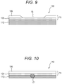
- Fig. 9 is a view illustrating the exposed part 16 in which the first layer 105 is exposed in Fig. 8 .
- the tower 11 is made of a steel material.
- a rolled material having a predetermined thickness is bent, one end is then bonded to the other end by welding at the longitudinal welded part 113 (113a, 113b), and the bonded material is processed into a cylinder shape like the tower cylinder 110a or 110b.
- a plurality of longitudinal welded parts 113 (113a, 113b) may be disposed on the circumferences of the tower cylinders 110a and 110b.
- One tower cylinder 110a or 110b is bonded to the other tower cylinder 110a or 110b by welding at a circumferential welded part 114 (114a, 114b). This step is repeated multiple times, and a tower assembly part 111 (111a, 111b) obtained by welding bonding is bonded to the other tower assembly part 111 (111a, 111b) by fastening bolts at a flange part 112 (112a, 112b).
- a revolving bearing (not illustrated), the nacelle 13 housing a power transmission system and a generator, the rotation axis 12, and a plurality of blades 10 (10a, 10b, 10c) is attached to the top of the tower 11.
- the tower 11 is exposed to an outdoor environment. Therefore, a substrate surface thereof is shaved by a raindrop or a dust, the surface is deteriorated by ultraviolet rays, or the first layer 105 is worn away or peeled by collision of a flying object such as a bird, snow, or a hailstone.
- a flying object such as a bird, snow, or a hailstone.
- the wind power generation equipment is installed near the seashore or on the sea, the first layer is worn away or peeled by a spray or salt of sea water, and the first layer 105 is exposed as illustrated in Fig. 9 . (Exposed part 16 of first layer generated by damage of substrate surface)
- the first layer 105 emits light by receiving an external force, and therefore only an exposed part emits light. At night, it is possible to specify a light emitting portion visually at a close distance and to specify a light emitting portion using a camera capable of photographing even at night at a long distance. At a point of time when disappearance of the first layer 105 is detected by emission, soundness of the substrate is maintained or the substrate is damaged slightly. Therefore, it is possible to repair the tower 11 properly before the damage of the tower 11 is enlarged.
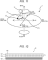
- Fig. 10 is an enlarged view of the longitudinal welded part 113 (113a, 113b) in Fig. 6 .
- a welded part such as the longitudinal welded part 113 (113a, 113b)
- a discontinuous part 17 is formed by welding, and therefore a stress is concentrated easily.
- the stress emission intensity of the first layer 105 which is exposed due to disappearance of the second layer 106 becomes higher and stronger light is emitted than in the smooth part described in Examples 1 and 2. Therefore, it is possible to detect damage on a surface of the structure material quickly.
- the substrate surface protection layer 15 including the first layer 105 and the second layer 106 may be disposed not only at the longitudinal welded part 113 (113a, 113b) of the tower 11 as in the present Example, but also, for example, at the flange part 112 (112a, 112b), a bonded part (welded part) such as the circumferential welded part 114 (114a, 114b), or a portion having a rapidly-changing shape or size.
- the surface protection layer is provided not only on the smooth part in the blade 10 or the tower 11, but also can be applied to the adhesively bonded part 102 of the front end 101a and the rear end 101b in the blade 10 or a bonded part of the outer skin of the web 103 (103a, 103b) and the girder member 104 (104a, 104b).
- the surface protection layer can be disposed on a bonded part between the plurality of members, a portion having a rapidly-changing shape or size, a notch such as a hole for fastening a bolt, or the like.
- An application range thereof is not limited according to a portion.
- the exposed part 16 is detected by detecting a difference in stress distribution caused by a difference in heat elastic modulus between the first layer 105 and the second layer 106 described in Example 1 or 2 by an infrared temperature measuring unit such as infrared thermography.
- the infrared thermography is a device for measuring an unsteady change in temperature.
- gas is expanded adiabatically, the temperature of the gas is lowered.
- gas is compressed adiabatically, the temperature of the gas is elevated.
- a stress is applied to solid suddenly, a similar phenomenon occurs. This is referred to as a heat elastic effect.
- ⁇ represents a value of stress fluctuation of an object
- T represents temperature
- K m represents heat elastic modulus.
- the heat elastic modulus K m is a specific numerical value determined by a thermophysical property of a material.
- Table 1 indicates a relation between thermophysical property values of typical structure materials used for the wind power generation equipment and the heat elastic modulus K m thereof.
- K m of iron (Fe) is 3.45 ⁇ 10 -6 N/mm 2 .
- a minute temperature fluctuation caused when a stress fluctuation occurs in a measurement object is measured by a measurement unit such as infrared thermography, and is converted into a value of stress fluctuation ⁇ based on Formula 1.
- Table 1 indicates conversion values of ⁇ at the temperature fluctuation of 1.0 mK in typical structure materials used for the wind power generation equipment.
- ⁇ of iron (Fe) is 0.97N/mm 2
- ⁇ of GFRP is 0.64 N/mm 2 . That is, it is indicated that a measured temperature fluctuation ⁇ T is high in a part where a high stress is generated in an object to be measured, such as a shape discontinuous part or a notch.
- the first layer 105 is made of a material having a different K m from that of the material of the second layer 106.
- the exposed part 16 can be detected as follows. That is, when the second layer 106 remains as in Figs. 4 and 8 , only ⁇ generated in the second layer 106 is measured. However, as in Figs. 5 and 9 , in the exposed part 16 in which the second layer 106 is exposed by disappearance of a part of the first layer 105, ⁇ generated in the first layer 105 and ⁇ generated in the second layer 106 are measured, and a difference in ⁇ therebetween is measured to detect the exposed part 16.
- the first layer 105 is made of a polymer resin material.
- a polyurethane resin an acrylic resin, a fluororesin, an olefin resin, a polyester resin, a polyamide resin, an epoxy resin, a phenol resin, a vinyl chloride resin, and a polycarbonate resin.
- a polyurethane resin or a fluororesin is preferably used from a viewpoint of light resistance.
- examples thereof include a copolymer and a blend of these synthetic resins.
- the second layer 106 is preferably made of a material having a different heat elastic modulus K m from the first layer 105.
- a fluororesin for the first layer 105 and using a polyurethane resin for the second layer 106 the temperature fluctuation ⁇ T when the stress fluctuation ⁇ is 1.0 N/mm 2 can be calculated to be 14 mK and 1.5 mK by Formula 1 with reference to Table 1, respectively.
- an infrared detecting unit such as infrared thermography, it is possible to detect the exposed part 16 of the first layer.
- the smooth part of the substrate has been exemplified.
- the first layer and the second layer can be disposed in a bonded part between the plurality of members, a curved surface portion having a rapidly-changing shape or size, or a notch.
- An application range thereof is not limited according to a portion.
- the material is not limited to the materials indicated in Table 1, and suitable materials can be combined to each other appropriately.
- the exposed part 16 is detected by a difference in color between the first layer 105 and the second layer 106 described in Example 1 or 2.
- the first layer 105 is formed of a layer having a different color from that of the second layer 106, and the exposed part 16 obtained by disappearance of the first layer 105 is detected by a color difference meter.
- Fig. 11 illustrates a color system expressing a color of an object, which is a L*a*b* color system 2 standardized by International Commission on Illumination in 1976 and established by JIS-Z8781-4:2013.
- a brightness is represented by L*
- a chromaticity expressing hue and chroma is represented by a* and b*.
- a* or b* indicates a direction of color.
- a* indicates a red direction
- -a* indicates a green direction
- b* indicates an yellow direction
- -b* indicates a blue direction.
- a numerical value thereof is larger, a color is clearer. As the numerical value goes toward the center, the color is darker.
- a difference in color can be represented by a numerical value of ⁇ E*ab23.
- a color difference between a color 21 of the first layer 105 and a color 22 of the exposed second layer 106 is determined with Formula 3 by a color measuring unit, for example, using a color meter manufactured by Konica Minolta, Inc.
- ⁇ E * ab ⁇ L * 2 + ⁇ a * 2 + ⁇ b * 2 1 / 2
- an arrangement of colors of the first layer 105 and the second layer 106 is not limited.
- the color difference ⁇ E*ab23 between the first layer 105 and the second layer 106 is determined with reference to the color system 2, and disappearance of the second layer 106 is detected using this value as a threshold during operation.
- the color system is not limited to the L*a*b* color system 2.
- a standardized color system such as a Munsell color system, an XYZ color system, an L*c*h color system, or a Hunter Lab color system may be used as a standard.
- An original color system may be used.
- a color difference can be determined by recording an image or a video in a recording device with a camera having a high resolution and performing post-processing using an image processing device. Under some conditions, it is also possible to determine a color difference visually without using a color difference meter.
- FIG. 12 is a view illustrating another embodiment of the surface protection layer 15 of the blade substrate 100.
- a third layer 107 containing a stress light emitting material different from that blended in the first layer 105 is disposed between the first layer 105 disposed on a surface of the blade substrate 100 and the second layer 106.
- Fig. 13 illustrates a state in which the surface protection layer 15 disposed on the surface of the blade substrate 100 is worn away in a plate thickness direction and the first layer 105 and the third layer 107 are exposed in a contour-like shape in the present Example.
- Examples of the stress light emitting material blended in the first layer 105 or the third layer 107 include a material containing zinc sulfide (ZnS), strontium aluminate (SrAl 2 O 4 ), or the like as a main component; a material having an unstable electron shell of 3d, 4d, 5d, or 4f in a base crystal of at least one metal oxide or complex oxide selected from MgAl 2 O 4 and CaAl 2 O 4 having a spinel structure, Al 2 O 3 having a corundum structure, and SrMgAl 10 O 17 having a ⁇ -alumina structure and containing at least one metal ion selected from rare earth metal ions and transition metal ions which can cause radiation transfer in this electron shell as a central ion of an emission center; a material containing at least one aluminate having a nonstoichiometric composition and having a lattice defect of emitting light when a carrier excited by mechanical energy returns to a ground state; a material containing
- examples thereof include a material obtained by adding an emission center containing at least one rare earth metal or transition metal which emits light when an electron excited by mechanical energy returns to a ground state to a base material containing at least one oxide of CaYAl 3 O 7 , Ca 2 Al 2 SiO 7 , Ca 2 (Mg,Fe)Si 2 O 7 , Ca 2 B 2 SiO 7 , CaNaAlSi 2 O 7 , Ca 2 MgSi 2 O 7 , (Ca,Na) 2 (Al,Mg) (Si,Al) 2 O 7 , and Ca 2 (Mg,Al) (Al,Si)SiO 7 having a melilite structure; and a material obtained by adding an emission center containing at least one rare earth metal or transition metal which emits light when an electron excited by mechanical energy returns to a ground state to a base material containing Sr 3 Al 2 O 6 or Ca 3 Al 2 O 6 having a FeS 2 structure, such as ceramics or strontium alumina
- an inorganic compound such as an aluminate or a silicate is used.
- fine particles of strontium aluminate (SrAl 2 O 4 :Eu) obtained by adding europium which is becoming general or zinc sulfide (ZnS:Mn) obtained by adding manganese, or the like are more preferable.
- These stress light emitting materials preferably have a spherical shape and a diameter of 1 ⁇ m to 10 ⁇ m in order to be filled in a synthetic resin or a synthetic fiber efficiently.
- a base material of the first layer 105 or the third layer 107 preferably has high transparency in order to highlight a state when the stress light emitting material emits light.
- Specific examples thereof include a polyurethane resin, an acrylic resin, a fluororesin, an olefin resin, a polyester resin, a polyamide resin, an epoxy resin, a phenol resin, a vinyl chloride resin, a polycarbonate resin, and a copolymer and a blend of these synthetic resins.
- a resin having a high surface hardness and a small elasticity is more preferable in order to transmit a stress sufficiently.
- the first layer 105 has a structure to perform stress emission of a color different from that of the third layer 107.
- strontium aluminate SrAl 2 O 4 :Eu
- zinc sulfide ZnS:Mn
- the second layer 106 is made of a polymer resin material.
- a polyurethane resin an acrylic resin, a fluororesin, an olefin resin, a polyester resin, a polyamide resin, an epoxy resin, a phenol resin, a vinyl chloride resin, and a polycarbonate resin.
- a polyurethane resin or a fluororesin is preferably used from a viewpoint of light resistance.
- examples thereof include a copolymer and a blend of these synthetic resins.
- the combination of materials is not limited only to the above materials, and the number of layers to constitute the surface protection layer is not limited.
- the substrate including the surface protection layer is not limited to the blade of the wind power generation equipment, but a similar effect can be obtained when the substrate is applied to a tower or the like.
- Example 4 or 5 the structure of the present Example can be applied.
- the structure of the present Example can be applied.
- FIG. 14 is a cross sectional view after the surface protection layer 15 is repaired in Fig. 12 described in Example 6, and includes the blade substrate 100, the first layer 105, the second layer 106, the third layer 107, a repair part 18, a repaired first layer 105a, and a repaired second layer 106a.
- the present Example is an example in which the repair part 18 has a structure different from a new one.
- the repaired first layer 105a may have a different plate thickness from the first layer 105
- the repaired second layer 106a may have a different plate thickness from the second layer 106.
- the repaired first layer 105a may be made of a material different from the new first layer 105.
- the layer number of the surface protection layer 15 is not limited.
- the substrate to be provided with the protection layer is not limited the blade of the present Example. Therefore, a similar effect can be obtained even when the repair is applied to another portion such as a tower.
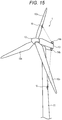
- Fig. 15 illustrates a wind power generation equipment provided with a substrate surface damage detecting system 14 (14a, 14b).
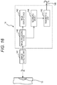
- Fig. 16 illustrates a detailed structure of the substrate surface damage detecting system 14.
- the substrate surface damage detecting system in the present Example includes a damage detecting unit 141 to detect damage, an image processing device 142 to perform image processing, an image display device 143 to display an image, a recording device 144 to record image processing data, a transmitting unit 145 to transmit the image processing data to the outside, and a communication cable 146 to connect the transmitting unit 145, that is, the substrate surface damage detecting system 14 to an external equipment or device.
- the damage detecting unit 141 is provided with any one of a CCD camera, an infrared camera, and a camera with a color difference meter according to the layer number of the surface protection layer 15 disposed on the substrate, the kind of each layer, and the film thickness of each layer.
- the color difference meter may be incorporated into the image processing device 142.
- Fig. 16 illustrates an example in which the transmitting unit 145 is connected to an external equipment or device using the communication cable 146. However, data may be transmitted to an external equipment or device wirelessly by disposing a wireless communication unit in the transmitting unit 145 or the like.
- the substrate surface damage detecting system 14 (14a, 14b) disposed in the nacelle 13 of the wind power generation equipment 1 detects the exposed part 16 (damaged part) generated on the substrate surface by any means described in Examples 1 to 7.
- the image processing device 142 includes a threshold-inputting unit to detect damage of the substrate surface.
- a threshold set in advance during operation of the wind power generation equipment is exceeded, a person in charge of maintenance is informed of a damaged portion requiring repair. It is possible to carry out a repair plan properly by recording the history of the repaired portion, the repair number of the whole, or the like in the recording device 144 and by recording and analyzing the tendency or frequency of the repaired portion. By feeding back these to a designer, a next-type wind power generation equipment is reinforced when being designed, and reliability can be enhanced.
- thresholds of a size (area) of a damaged region, a magnitude of emission intensity, a difference in color (color difference), and the like are used.
- a damage quantitative value (degree of damage) of the exposed part 16 (damaged part), extracted by image processing performed by the image processing device, is compared with the threshold.
- a place to install the substrate surface damage detecting system 14 is only required to be a portion capable of monitoring the substrate of the wind power generation equipment 1.
- a height or a position to be installed is not limited.
- the substrate surface damage detecting system 14 may be attached to the tower 11.
- Fig. 17 illustrates a set type wind power generation equipment (wind farm) 19 provided with the substrate surface damage detecting system 14.
- the detailed structure of Fig. 17 is almost similar to that of Example 8. It is preferable for the damage detecting unit 141 to use a damage detecting device having a high resolution, capable of photographing even at a long distance.
- the substrate surface damage detecting system 14 of the wind farm 19 is installed at a remote place, that is, at a place far away from each wind power generation equipment.
- the wind power generation equipment when the wind power generation equipment is installed on land, on the seashore (along the coast), or on the sea, it is possible to monitor a state of the wind power generation equipment or the wind farm 19 including a plurality of wind power generation equipments from a remote place. Therefore, it is possible to reduce the number of the substrate surface damage detecting system 14 installed.
- the structure material according to an aspect of the present invention has been described mainly using an example of the wind power generation equipment.
- a similar effect can be obtained even when the structure material is applied to a railway vehicle, an automobile body, an airplane body, a pressure vessel used for various plant equipments, or the like, exposed to an outdoor severe environment, like the wind power generation equipment.
- the present invention is not limited to the above Examples, but includes various modification examples.
- the above Examples have been described in detail in order to explain the present invention to be understood easily.
- the present invention does not necessarily include all the components described above. It is possible to replace some components of an Example with components of another Example. It is also possible to add some components of an Example to another Example. In addition, some components of an Example can be deleted or replaced by other components, or another component can be added thereto.
Landscapes
- Engineering & Computer Science (AREA)
- Physics & Mathematics (AREA)
- General Physics & Mathematics (AREA)
- Chemical & Material Sciences (AREA)
- Life Sciences & Earth Sciences (AREA)
- Aviation & Aerospace Engineering (AREA)
- Sustainable Development (AREA)
- General Engineering & Computer Science (AREA)
- Sustainable Energy (AREA)
- Mechanical Engineering (AREA)
- Combustion & Propulsion (AREA)
- Health & Medical Sciences (AREA)
- Analytical Chemistry (AREA)
- Biochemistry (AREA)
- General Health & Medical Sciences (AREA)
- Immunology (AREA)
- Pathology (AREA)
- Electromagnetism (AREA)
- Wind Motors (AREA)
Applications Claiming Priority (1)
| Application Number | Priority Date | Filing Date | Title |
|---|---|---|---|
| JP2015020865A JP6469467B2 (ja) | 2015-02-05 | 2015-02-05 | 構造材および風力発電設備、風力発電システム |
Publications (1)
| Publication Number | Publication Date |
|---|---|
| EP3054154A1 true EP3054154A1 (en) | 2016-08-10 |
Family
ID=55486453
Family Applications (1)
| Application Number | Title | Priority Date | Filing Date |
|---|---|---|---|
| EP16154296.4A Withdrawn EP3054154A1 (en) | 2015-02-05 | 2016-02-04 | Structure material, wind power generation equipment, and wind power generation system |
Country Status (2)
| Country | Link |
|---|---|
| EP (1) | EP3054154A1 (https=) |
| JP (1) | JP6469467B2 (https=) |
Cited By (2)
| Publication number | Priority date | Publication date | Assignee | Title |
|---|---|---|---|---|
| TWI648189B (zh) * | 2016-12-01 | 2019-01-21 | 日商山葉發動機股份有限公司 | 傾斜車輛 |
| CN114000989A (zh) * | 2021-11-30 | 2022-02-01 | 中国华能集团清洁能源技术研究院有限公司 | 一种风力发电机组叶片气动性能衰减检测方法及测试系统 |
Families Citing this family (5)
| Publication number | Priority date | Publication date | Assignee | Title |
|---|---|---|---|---|
| WO2020054460A1 (ja) * | 2018-09-10 | 2020-03-19 | 国立研究開発法人産業技術総合研究所 | 内部空間を有する構造物およびその異常検出システム |
| JP6857432B1 (ja) * | 2020-08-31 | 2021-04-14 | 有限会社讃宝住設 | 風力発電設備のブレードの非接触検査方法 |
| JP7044283B2 (ja) * | 2020-08-31 | 2022-03-30 | 有限会社讃宝住設 | 風力発電設備のブレードの非接触検査方法 |
| JP7611870B2 (ja) * | 2022-04-25 | 2025-01-10 | 北海道電力株式会社 | 鉄筋コンクリート構造物の内部鉄筋の検査装置及び検査方法 |
| JP7473143B1 (ja) | 2023-12-13 | 2024-04-23 | 株式会社日立パワーソリューションズ | 風力発電設備の保守支援システム及び保守支援方法 |
Citations (10)
| Publication number | Priority date | Publication date | Assignee | Title |
|---|---|---|---|---|
| US6974641B1 (en) * | 1998-07-27 | 2005-12-13 | Southside Thermal Sciences (Sts) Limited | Thermal barrier coating with thermoluminescent indicator material embedded therein |
| JP2007101278A (ja) * | 2005-09-30 | 2007-04-19 | National Institute Of Advanced Industrial & Technology | 応力−ひずみ検出システム |
| JP2011021988A (ja) | 2009-07-15 | 2011-02-03 | Mitsubishi Heavy Ind Ltd | 腐食検知装置及び屋外構造物 |
| DE202011104315U1 (de) * | 2011-08-15 | 2012-11-20 | Repower Systems Se | Markierungslaminat |
| JP2013155062A (ja) | 2012-01-27 | 2013-08-15 | Komaihaltec Inc | コンクリート構造物の表面被覆材とこれを用いた変状検知方法 |
| US20130220005A1 (en) * | 2012-02-24 | 2013-08-29 | Mitsubishi Heavy Industries, Ltd. | Wind turbine blade, method for manufacturing wind turbine blade, and wind power generator and wind turbine blade monitoring system including wind turbine blade |
| WO2013131516A2 (de) * | 2012-03-05 | 2013-09-12 | Igus Ingenieurgemeinschaft Umweltschutz Mess- Und Verfahrenstechnik G.M.B.H. | Verfahren und vorrichtung zur überwachung des oberflächenzustandes von bauteilen |
| JP2013246097A (ja) * | 2012-05-28 | 2013-12-09 | Central Research Institute Of Electric Power Industry | コーティング層における剥離の非破壊検査方法および非破壊検査装置 |
| EP2679769A2 (en) * | 2012-06-27 | 2014-01-01 | General Electric Company | Turbomachine monitoring system and method |
| JP2014519024A (ja) | 2011-05-11 | 2014-08-07 | ヴォッベン プロパティーズ ゲーエムベーハー | ロータブレードの診断 |
Family Cites Families (3)
| Publication number | Priority date | Publication date | Assignee | Title |
|---|---|---|---|---|
| JPS62180695U (https=) * | 1986-05-09 | 1987-11-16 | ||
| JPH0517174U (ja) * | 1991-08-15 | 1993-03-05 | 三菱重工業株式会社 | 風車翼 |
| WO2006085424A1 (ja) * | 2005-02-09 | 2006-08-17 | National Institute Of Advanced Industrial Science And Technology | 応力解析方法及び応力解析装置 |
-
2015
- 2015-02-05 JP JP2015020865A patent/JP6469467B2/ja active Active
-
2016
- 2016-02-04 EP EP16154296.4A patent/EP3054154A1/en not_active Withdrawn
Patent Citations (10)
| Publication number | Priority date | Publication date | Assignee | Title |
|---|---|---|---|---|
| US6974641B1 (en) * | 1998-07-27 | 2005-12-13 | Southside Thermal Sciences (Sts) Limited | Thermal barrier coating with thermoluminescent indicator material embedded therein |
| JP2007101278A (ja) * | 2005-09-30 | 2007-04-19 | National Institute Of Advanced Industrial & Technology | 応力−ひずみ検出システム |
| JP2011021988A (ja) | 2009-07-15 | 2011-02-03 | Mitsubishi Heavy Ind Ltd | 腐食検知装置及び屋外構造物 |
| JP2014519024A (ja) | 2011-05-11 | 2014-08-07 | ヴォッベン プロパティーズ ゲーエムベーハー | ロータブレードの診断 |
| DE202011104315U1 (de) * | 2011-08-15 | 2012-11-20 | Repower Systems Se | Markierungslaminat |
| JP2013155062A (ja) | 2012-01-27 | 2013-08-15 | Komaihaltec Inc | コンクリート構造物の表面被覆材とこれを用いた変状検知方法 |
| US20130220005A1 (en) * | 2012-02-24 | 2013-08-29 | Mitsubishi Heavy Industries, Ltd. | Wind turbine blade, method for manufacturing wind turbine blade, and wind power generator and wind turbine blade monitoring system including wind turbine blade |
| WO2013131516A2 (de) * | 2012-03-05 | 2013-09-12 | Igus Ingenieurgemeinschaft Umweltschutz Mess- Und Verfahrenstechnik G.M.B.H. | Verfahren und vorrichtung zur überwachung des oberflächenzustandes von bauteilen |
| JP2013246097A (ja) * | 2012-05-28 | 2013-12-09 | Central Research Institute Of Electric Power Industry | コーティング層における剥離の非破壊検査方法および非破壊検査装置 |
| EP2679769A2 (en) * | 2012-06-27 | 2014-01-01 | General Electric Company | Turbomachine monitoring system and method |
Cited By (3)
| Publication number | Priority date | Publication date | Assignee | Title |
|---|---|---|---|---|
| TWI648189B (zh) * | 2016-12-01 | 2019-01-21 | 日商山葉發動機股份有限公司 | 傾斜車輛 |
| US11753099B2 (en) | 2016-12-01 | 2023-09-12 | Yamaha Hatsudoki Kabushiki Kaisha | Leaning vehicle |
| CN114000989A (zh) * | 2021-11-30 | 2022-02-01 | 中国华能集团清洁能源技术研究院有限公司 | 一种风力发电机组叶片气动性能衰减检测方法及测试系统 |
Also Published As
| Publication number | Publication date |
|---|---|
| JP2016142237A (ja) | 2016-08-08 |
| JP6469467B2 (ja) | 2019-02-13 |
Similar Documents
| Publication | Publication Date | Title |
|---|---|---|
| EP3054154A1 (en) | Structure material, wind power generation equipment, and wind power generation system | |
| US8605263B2 (en) | Wind turbine blades strain measuring system during static tests | |
| Baker et al. | Towards a practical structural health monitoring technology for patched cracks in aircraft structure | |
| ES2646182T3 (es) | Método y aparato para la detección de corrosión no destructiva mediante puntos cuánticos. | |
| EP2676113B1 (en) | System and method for detecting damage to a wind turbine blade | |
| US9085052B1 (en) | Structural repair having optical witness and method of monitoring repair performance | |
| GB2194062A (en) | Detection of damage in materials | |
| US10378517B2 (en) | Method for replacing the blades of a wind turbine to maintain safe operation | |
| US8739612B2 (en) | Wear control apparatus and wind turbine blade monitoring system including wind turbine blade | |
| US20200189553A1 (en) | Method and system for monitoring the state of a brake of an aircraft | |
| US7647809B1 (en) | Approach for indicating the occurrence of a mechanical impact on a material, such as a low-ductility composite material | |
| US8387469B2 (en) | Systems, methods, and apparatus for structural health monitoring | |
| CN109556770A (zh) | 一种智能锚栓和带有该智能锚栓的钢板支撑结构 | |
| JP2001153788A (ja) | 構造体の劣化診断方法及び蛍光構造体 | |
| RU2645431C1 (ru) | Способ обнаружения ударных повреждений конструкции | |
| Liersch et al. | Investigation of the impact of rain and particle erosion on rotor blade aerodynamics with an erosion test facility to enhancing the rotor blade performance and durability | |
| JP5187695B2 (ja) | 放射散逸の解析による部品の非破壊検査装置 | |
| CN114458550A (zh) | 一种风力发电机叶片裂纹的识别方法 | |
| Krankenhagen et al. | Thermographic rotor blade inspection from larger distances–a promising tool for the maintenance of wind turbines | |
| JP6961776B1 (ja) | 検査方法 | |
| Zhuge et al. | Influence of color coatings on aircraft surface ice detection based on multi-wavelength imaging | |
| Martyanov et al. | Analytical research of wind farms damage | |
| JP2019138459A (ja) | 螺子締結体および螺子締結体の緩み検出方法 | |
| Davis et al. | Smart appliques for corrosion protection and health monitoring | |
| Heikkilä et al. | PerforMAnce of An enercon WinD turBines unDer icinG conDitions in euroPe |
Legal Events
| Date | Code | Title | Description |
|---|---|---|---|
| PUAI | Public reference made under article 153(3) epc to a published international application that has entered the european phase |
Free format text: ORIGINAL CODE: 0009012 |
|
| 17P | Request for examination filed |
Effective date: 20160330 |
|
| AK | Designated contracting states |
Kind code of ref document: A1 Designated state(s): AL AT BE BG CH CY CZ DE DK EE ES FI FR GB GR HR HU IE IS IT LI LT LU LV MC MK MT NL NO PL PT RO RS SE SI SK SM TR |
|
| AX | Request for extension of the european patent |
Extension state: BA ME |
|
| STAA | Information on the status of an ep patent application or granted ep patent |
Free format text: STATUS: EXAMINATION IS IN PROGRESS |
|
| 17Q | First examination report despatched |
Effective date: 20180102 |
|
| STAA | Information on the status of an ep patent application or granted ep patent |
Free format text: STATUS: THE APPLICATION IS DEEMED TO BE WITHDRAWN |
|
| 18D | Application deemed to be withdrawn |
Effective date: 20190903 |