EP3050785B1 - Motorcycle - Google Patents
Motorcycle Download PDFInfo
- Publication number
- EP3050785B1 EP3050785B1 EP13894188.5A EP13894188A EP3050785B1 EP 3050785 B1 EP3050785 B1 EP 3050785B1 EP 13894188 A EP13894188 A EP 13894188A EP 3050785 B1 EP3050785 B1 EP 3050785B1
- Authority
- EP
- European Patent Office
- Prior art keywords
- motorcycle
- rear fender
- fender
- mounting portions
- mounting
- Prior art date
- Legal status (The legal status is an assumption and is not a legal conclusion. Google has not performed a legal analysis and makes no representation as to the accuracy of the status listed.)
- Not-in-force
Links
Images


Classifications
-
- B—PERFORMING OPERATIONS; TRANSPORTING
- B62—LAND VEHICLES FOR TRAVELLING OTHERWISE THAN ON RAILS
- B62J—CYCLE SADDLES OR SEATS; AUXILIARY DEVICES OR ACCESSORIES SPECIALLY ADAPTED TO CYCLES AND NOT OTHERWISE PROVIDED FOR, e.g. ARTICLE CARRIERS OR CYCLE PROTECTORS
- B62J50/00—Arrangements specially adapted for use on cycles not provided for in main groups B62J1/00 - B62J45/00
- B62J50/20—Information-providing devices
- B62J50/25—Information-providing devices intended to provide information to other road users, e.g. signs or flags
- B62J50/26—Number plates
-
- B—PERFORMING OPERATIONS; TRANSPORTING
- B62—LAND VEHICLES FOR TRAVELLING OTHERWISE THAN ON RAILS
- B62J—CYCLE SADDLES OR SEATS; AUXILIARY DEVICES OR ACCESSORIES SPECIALLY ADAPTED TO CYCLES AND NOT OTHERWISE PROVIDED FOR, e.g. ARTICLE CARRIERS OR CYCLE PROTECTORS
- B62J15/00—Mud-guards for wheels
- B62J15/02—Fastening means; Stays
-
- B—PERFORMING OPERATIONS; TRANSPORTING
- B62—LAND VEHICLES FOR TRAVELLING OTHERWISE THAN ON RAILS
- B62J—CYCLE SADDLES OR SEATS; AUXILIARY DEVICES OR ACCESSORIES SPECIALLY ADAPTED TO CYCLES AND NOT OTHERWISE PROVIDED FOR, e.g. ARTICLE CARRIERS OR CYCLE PROTECTORS
- B62J6/00—Arrangement of optical signalling or lighting devices on cycles; Mounting or supporting thereof; Circuits therefor
- B62J6/04—Rear lights
-
- B—PERFORMING OPERATIONS; TRANSPORTING
- B62—LAND VEHICLES FOR TRAVELLING OTHERWISE THAN ON RAILS
- B62J—CYCLE SADDLES OR SEATS; AUXILIARY DEVICES OR ACCESSORIES SPECIALLY ADAPTED TO CYCLES AND NOT OTHERWISE PROVIDED FOR, e.g. ARTICLE CARRIERS OR CYCLE PROTECTORS
- B62J6/00—Arrangement of optical signalling or lighting devices on cycles; Mounting or supporting thereof; Circuits therefor
- B62J6/20—Arrangement of reflectors, e.g. on the wheel spokes ; Lighting devices mounted on wheel spokes
-
- B—PERFORMING OPERATIONS; TRANSPORTING
- B62—LAND VEHICLES FOR TRAVELLING OTHERWISE THAN ON RAILS
- B62K—CYCLES; CYCLE FRAMES; CYCLE STEERING DEVICES; RIDER-OPERATED TERMINAL CONTROLS SPECIALLY ADAPTED FOR CYCLES; CYCLE AXLE SUSPENSIONS; CYCLE SIDE-CARS, FORECARS, OR THE LIKE
- B62K2202/00—Motorised scooters
Definitions
- the present invention relates to a motorcycle, and in particular, to a structure for mounting a plate member indicating information identifying the motorcycle.
- License plates attached to motorcycles indicate information identifying the motorcycles.
- the plural kinds of the license plates have different shapes or mounted positions in different countries.
- a structure designed to mount these kinds of the license plates is disclosed in patent literature 1 below.
- the rear fender has a rear surface including license plate mounting portions, which define plural pairs of mounting holes.
- a license plate is attached using selected ones of the mounting holes suitable for the kind of the license plate.
- the license plate mounting portions which define the plural mounting holes to support left and right sides of the license plate, have complex structures protruding in left and right directions. To prevent vibrating of the license plate, the license plate mounting portions are desired to reduce vibration transmitted thereto. To meet such needs, the license plate mounting portions, which have the complex structures and define the plurality of mounting holes, need to be thicker enough to reduce the vibration.
- a desirable rear fender is simply configured to reduce the vibration, as well as to allow for mounting different kinds of license plates for the different countries.
- Patent Literature 1 JP-A-2011-46302 , JP H11 198880 A , EP 2557 025 A1 , which shows all the features of the preamble of claim 1.
- a motorcycle comprising: a rear fender disposed on a rear part of a motorcycle frame of the motorcycle for preventing splash of muddy water as the muddy water is forced upwardly by a rear wheel of the motorcycle; fasteners disposed on rear surfaces of the rear fender and fastened to the rear fender; a lamp disposed above the rear fender for illuminating the rear surfaces; a reflector disposed adjacent the rear surfaces for reflecting light from a rear direction of the motorcycle; and a plate member disposed on the rear fender; wherein the rear fender includes a plurality of mounting portions, wherein the fasteners pass through any ones of the mounting portions and are fastened to the rear fender, wherein the rear surfaces comprise at least one left rear surface and at least one right rear surface when the rear surfaces are viewed in rear elevation, and wherein the rear fender includes a central portion provided between the left and right rear surfaces and recessed forward relative to the rear surfaces.
- the rear surfaces include opposite lateral outer ends spaced apart in a widthwise direction of the motorcycle, wherein the rear fender further includes: lateral surfaces protruding from the opposite lateral outer ends of the rear surfaces in a forward direction of the motorcycle.
- the invention is characterised in that the rear fender includes depressions recessed from the rear surfaces to the lateral surfaces, and also in that the plate member is attached to the left and right rear surfaces, wherein projections protrude from a back surface of the plate member and are received within the depressions of the rear fender.
- each of the depressions is provided between adjacent ones of the plurality of mounting portions when the depressions are viewed in rear elevation, the adjacent mounting portions being arranged vertically.
- each of the mounting portions has an oblong shape elongated in the widthwise direction of the motorcycle.
- the rear fender further includes a rearward protruding portion provided below the mounting portions of the rear fender.
- the mounting portions are provided in pairs, the number of the pairs being at least two.
- the rear fender further includes a lower mounting portion provided below the protruding portion, and the lower mounting portion selectively has a mounting hole formed therethrough.
- the rear fender includes the plurality of mounting portions.
- the fasteners which pass through any ones of the mounting portions, are fastened to the rear fender.
- the mounting portions corresponding to a kind of a member to be attached to the rear fender have openings therethrough while the other mounting portions have no through-holes.
- the rear fender which has the minimum number of mounting holes necessary for the attachment of the member, is highly rigid. Such a simple configuration of the rear fender reduces vibration, in addition to allowing attachment of different kinds of members for different countries.
- the rear surfaces comprise the at least one left rear surface and the at least one right rear surface when the rear surfaces are viewed in rear elevation, and the rear fender includes the central portion recessed forward relative to the rear surfaces.
- the central recessed portion enhances rigidity of the rear fender, thus reducing the vibration.
- the rear surfaces include the opposite lateral outer ends spaced apart in the widthwise direction of the motorcycle, wherein the rear fender further includes: the lateral surfaces protruding from the opposite lateral outer ends of the rear surfaces in the forward direction of the motorcycle; and the depressions recessed from the rear surfaces to the lateral surfaces, and wherein each of the rear surfaces has the U-shape laterally opened by the depression.
- the depressions of the rear fender which can receive projections on a back surface of a member, allows appropriate abutment of the member on the rear surfaces of the rear fender in attaching the member to the rear surfaces.
- each of the depressions is provided between the adjacent ones of the plurality of mounting portions when the depressions are viewed in rear elevation, the adjacent mounting portions being arranged vertically.
- the projections are positioned in place by insertion into the depressions. This facilitates the attachment of the member to the rear fender.
- each of the mounting portions has the oblong shape elongated in the widthwise direction of the motorcycle.
- the oblong mounting portion can have an opening formed therethrough over a wide range elongated in the widthwise direction. This allows positional adjustment of a member in the widthwise direction, thus facilitating attachment of the member. Additionally, the mounting portion allows different members to be attached to different positions in the widthwise direction.
- the rear fender further includes the rearward protruding portion provided below the mounting portions.
- the protruding portion can abut on and thus flex a member. This reduces vibration transmitted to the member.
- the mounting portions are provided in pairs, the number of the pairs being at least two.
- the selected mounting portions corresponding to a kind of a member have openings therethrough. Such mounting portions thus correspond to different kinds of members.
- the rear fender further includes the lower mounting portion provided below the protruding portion, and the lower mounting portion selectively has the mounting hole formed therethrough.
- a member can be attached to the lower mounting portion through a stay, which appropriately adjusts an angle of the member. The appropriately adjusted angle of the member allows the lamp to appropriately illuminate the member.
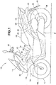
- a motorcycle 10 includes a motorcycle frame 11, a power unit 21 pivotably suspended on a rear part of the frame 11, and a motorcycle cover 31 covering the frame 11.
- the frame 11 includes a head pipe 12, a main frame 13 extending rearward and downward from the head pipe 12, and seat rails 14 extending rearward and upward from a rear end of the main frame 13.
- the head pipe 12 has a bottom supporting a front fork 16L through a bottom bridge 15.
- the reference characters "L" and “R” as used herein are suffixes indicating the left and the right, respectively.
- a front wheel 17 is rotatably supported by the front fork 16L.
- a handle 18 for steering the front wheel 17 is disposed on a top of the head pipe 12.
- a rider's seat 19 is disposed above the seat rails 14.
- the power unit 21 includes an intake cleaner 22, an exhaust muffler 23, and a rear wheel 24 as a drive wheel.
- Left and right rear cushions 25 are disposed between the power unit 21 and the pair of the seat rails 14 for absorbing impact.
- the motorcycle cover 31 includes a front cover 32 covering a front side of the head pipe 12, a main frame cover 33 covering an upper side of the main frame 13, a side cover 34 covering opposite lateral sides of the main frame 13, and a rear cover 35 covering the set rails 14.
- a front fender 36 covers an upper side of the front wheel 17, and a rear fender 40 covers an upper side of the rear wheel 24.
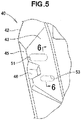
- a plate member 60 indicating information identifying the motorcycle (hereinafter referred to as "vehicle 20") is disposed on the rear fender 40.
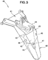
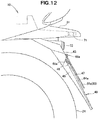
- the rear fender 40 includes a horizontal portion 41 extending generally horizontally, and a rear hung portion 42 extending from a lower part of the horizontal portion 41 in a downward and rearward direction.
- the plate member 60 is attached to rear surfaces 43 of the rear hung portion 42.
- the horizontal portion 44 has a horizontal extension 44 extending in a rearward direction of the vehicle.
- the horizontal extension 44 is positioned at an upper part of the rear fender 40.
- the rear fender 40 has a lamp 71 disposed on a rear end of the horizontal extension 44 for illuminating the plate member 60.
- the rear fender 40 further has a reflector 72 disposed adjacent the plate member 60 for reflecting light from the rearward direction.
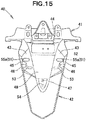
- the rear fender 40 includes the left and right planar rear surfaces 43, 43 separated from each other, and lateral surfaces 45 projecting from the corresponding lateral outer ends of the rear surfaces 43 in a forward direction of the vehicle. It is to be noted that the lateral outer ends of the individual rear surfaces 43 are spaced from each other in a widthwise direction of the vehicle.
- the lateral surface 45 is angled relative to the rear surface 43.
- a depression 46 is formed adjacent a lateral outer edge of the rear surface 43.
- the depression 46 is recessed from the rear surface 43 to the lateral surface 45.
- the plate member 60 is attached to the left and right rear surfaces 43, 43.
- the depression, or recessed portion 46 which is formed at an end portion of the rear fender 40, facilitates the attachment of the plate member having projections on the back surface thereof. This enhances the workability.
- the recessed portion 46 is provided at an outer end of each of the left and right rear surfaces 43, the recessed portion 46 may be provided on any portion of each rear surface 43, and further be plural in number.
- the rear hung portion 42 has a rearward protruding portion 47 provided at a vertical middle thereof.
- the plate member 60 may be large-sized enough to abut on the protruding portion 47.
- the rear fender 40 which has the recessed central portion 49, has an increased rigidity sufficient to reduce vibration of the rear fender 40.
- the rear fender 40 includes a plurality of mounting portions 51, 53 on the rear surfaces 43.
- Each of the mounting portions 51, 53 which is in the shape of an oblong hole elongated in the widthwise direction of the vehicle, is provided in a pair so that the left and right mounting portions 51 are arranged while the left and right mounting portions 53 are arranged.
- the plate member 60 ( Fig. 2 ) is fastened to the rear fender 40 by a fastener passing through any ones of the mounting portions 51, 53.
- a lower mounting portion 54 which selectively has a mounting hole formed therethrough.
- the plate member 60 can be attached to the lower mounting portion 54 through a stay, which appropriately adjusts an angle of the plate member 60.
- the one pair of the mounting portions 51 or 53 corresponding to the kind of the plate member 60 has holes formed therethrough for attachment of the plate member to the rear fender while the other pair of the mounting portions has no holes.
- the rear fender 40 which has the minimum number of the required mounting holes, is highly rigid. Such a simple configuration of the rear fender 40 reduces vibration transmitted to the rear fender 40.
- the recessed portion 46 which is provided near the plurality of the mounting portions 51, 53, achieves an increased rigidity of the surroundings of the mounting locations of the rear fender 40 to which the plate member 60 is attached. This reduces vibration transmitted to the plate member 60.
- the mounting portions 51, 53 on the rear surface 43 of the rear fender 40 are positioned in correspondence to different attachment portions of different kinds of plate members.
- the first mounting portion 51 which is oblong, or elongated in the widthwise direction when viewed in rear elevation, is positioned proximate the lateral outer edge of the rear surface 43.
- the second mounting portion 53 which is oblong, or elongated in the widthwise direction when viewed in rear elevation, is positioned below the first mounting portion 51.
- the mounting portions 51, 53 are oblong in the above embodiment.
- the mounting portions may have other appropriate shapes such as circular shapes in correspondence to the kind of the plate member.
- the first mounting portion 51 has a diameter D1.
- the second mounting portion 53 has a diameter D2.
- the diameter D2 is smaller than the diameter D1 (D2 > D1).
- the rear fender 40 has a thickness T1.
- the mounting portions 51, 53 have thicknesses T2.
- the diameter D2 is smaller than the diameter D1 (D2 ⁇ D1).
- the diameters D1, D2 may be appropriately set in correspondence to the kind of the plate member 60, so that, for example, the diameter D1 is smaller than the diameter D2 (D1 ⁇ D2).
- the mounting portions 51, 53 have the same thickness.
- the mounting portions 51, 53 may have their thicknesses appropriately set in correspondence to the shapes or sizes of the mounting portions 51, 53.
- the rear fender 40 is formed by injection molding.
- the mounting portions 51, 53 have mounting holes 55a, 55c partially formed therethrough.
- the mounting holes 55a, 55c are made using different cores placed in a mold during the injection molding.
- the plate member is a license plate 60a indicating information identifying the vehicle.
- the license plate 60a includes a rectangular, flat plate portion 61a indicating a line of letters, and an edge portion 62a reinforcing a circumference of the flat plate portion 61a.
- the plate 60a also includes a depression 63a elongated in the widthwise direction and formed on an upper part of the flat plate portion 61a.
- the plate 60a further includes rivets 65a disposed on left and right ends of the depression 63a and protruding out of a back surface 64a.
- the plate 60a further includes through-holes 66a formed above left and right portions of the depression 63a and elongated in the widthwise direction.
- the license plate 60a has its length L1 and width W1.
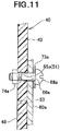
- the mounting hole 55a is formed on the rear surface 43 of the rear fender 40.
- the mounting portion 53 remains solid without defining any through-holes. This achieves an increased rigidity of the rear fender 40.
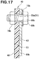
- the license plate 60a is fastened to the rear fender 40 by fasteners 68a.
- the fastener 68a which passes through a washer 73a, the through-hole 66a of the license plate 60a and the mounting hole 55a of the rear fender 40, is tightened to a nut 74a on a back surface 48 of the rear fender 40.
- the rivet 65a protruding out of the back surface 64a of the license plate 60a is received within the recessed portion 46 of the rear fender 40.
- the recessed portion 46 which receives the projection or rivet 65a on the back surface 64a of the license plate 60a, allows the license plate 60a to be appropriately attached to the rear fender 40.
- Such a structure of the rear fender 40 allows for attachment of different types of license plates thereto.
- the license plate 60a has a lower portion abutting on the protruding portion 47 of the rear fender 40.
- the plate member is a license plate 60b indicating information identifying the vehicle.
- the license plate 60b includes a rectangular, flat plate portion 61b indicating a line of letters, and an edge portion 62b reinforcing a circumference of the flat plate portion 61b.
- the plate 60b further includes through-holes 66b formed above left and right portions of the flat plate portion 61b.
- the license plate 60b has its length L2 and width W2.
- a fastener 68b which passes from a back surface 64b of the license plate 60b through a nut 74b and the through-hole 66b, is secured to a pin covered with a cap 69b disposed on a front surface of the license plate 60b.
- the first mounting portion 51 ( Fig. 9 ) of the rear fender 40 has the mounting hole 55a formed therethrough using a core during injection molding.
- the rear surface 43 of the rear fender 40 defines openings all of which are the mounting holes 55a.
- the mounting portions 53 remain solid without defining any through-holes. This achieves an increased rigidity of the rear fender 40.
- the license plate 60b is fastened to the rear fender 40 by the fastener 68b.
- the fastener 68b which passes through a washer 73b, the through-hole 66b of the license plate 60b and the mounting hole 55a of the rear fender 40, is tightened to a nut 74b on the back surface 48 of the rear fender 40.
- the back surface 64b of the license plate 60b is set on the rear surface 43 of the rear fender 40.
- the license plate 60b which covers and thus hides the recessed portion 46, achieves an improved outer visual appearance of the rear fender 40.
- the plate member is a license plate 60c indicating information identifying the vehicle.
- the license plate 60c includes a rectangular, flat plate portion 61c indicating a line of letters, and an edge portion 62c reinforcing a circumference of the flat plate portion 61c.
- the plate 60c further includes through-holes 66c formed above left and right portions of the flat plate portion 61c.
- the license plate 60c has its length L3 and width W3.
- the second mounting portion 53 ( Fig. 9 ) of the rear fender 40 has the mounting hole 55c formed therethrough using a core during injection molding.
- the rear surface 43 of the rear fender 40 defines openings all of which are the mounting holes 55c.
- the mounting portions 51, 52 remain solid without being punched therethrough. This achieves an increased rigidity of the rear fender 40.
- the mounting hole 55c which has an oblong shape elongated in the widthwise direction, provides a longer range within which to attach the license plate 60c ( Fig. 19 ) to the rear fender. This allows positional adjustment of the license plate 60c ( Fig. 19 ) in the widthwise direction, such that the license plate is attached at the adjusted position.
- the oblong mounting holes allow the license plate 60c to be attached at different positions arranged in the widthwise direction.
- the license plate 60c is fastened to the rear fender 40 by a fastener 68c.
- the fastener 68c which passes through a washer 73c, the through-hole 66c of the license plate 60c and the mounting hole 55c, is tightened to a nut 74c on the back surface 48 of the rear fender 40.
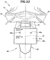
- the license plate 60c is attached to the rear surface 43 of the rear fender 40.
- the license plate 60c has a lower portion abutting on the protruding portion 47 of the rear fender 40.
- the abutment flexes the license plate 60c attached to the rear fender 40. This reduces vibration transmitted to the license plate 60c.
- the plate member 60 is attached directly to the rear fender.
- the plate member 60 may be attached through a stay to the rear fender 40.
- an angle of the plate member 60 relative to the lamp 71 may be appropriately changed.
- the three pairs of the respective mounting portions 51, 53 are provided throughout the Embodiments.
- the mounting portions 51, 53 may be provided in four or five pairs, and may have their shapes, sizes and positions appropriately modified.
- the present invention is preferably applicable to a motorcycle including a rear fender and a license plate attached to the rear fender.
Applications Claiming Priority (1)
| Application Number | Priority Date | Filing Date | Title |
|---|---|---|---|
| PCT/JP2013/076320 WO2015045111A1 (ja) | 2013-09-27 | 2013-09-27 | 自動二輪車 |
Publications (3)
| Publication Number | Publication Date |
|---|---|
| EP3050785A1 EP3050785A1 (en) | 2016-08-03 |
| EP3050785A4 EP3050785A4 (en) | 2017-06-21 |
| EP3050785B1 true EP3050785B1 (en) | 2019-07-17 |
Family
ID=52742314
Family Applications (1)
| Application Number | Title | Priority Date | Filing Date |
|---|---|---|---|
| EP13894188.5A Not-in-force EP3050785B1 (en) | 2013-09-27 | 2013-09-27 | Motorcycle |
Country Status (9)
| Country | Link |
|---|---|
| US (1) | US9481422B2 (ja) |
| EP (1) | EP3050785B1 (ja) |
| JP (1) | JP6093447B2 (ja) |
| CN (1) | CN105579334B (ja) |
| AU (1) | AU2013401282B2 (ja) |
| BR (1) | BR112016005983B1 (ja) |
| CA (1) | CA2924947C (ja) |
| MY (1) | MY175509A (ja) |
| WO (1) | WO2015045111A1 (ja) |
Families Citing this family (9)
| Publication number | Priority date | Publication date | Assignee | Title |
|---|---|---|---|---|
| JP6096915B2 (ja) * | 2013-09-27 | 2017-03-15 | 本田技研工業株式会社 | 自動二輪車 |
| DE102015108549A1 (de) * | 2015-05-29 | 2016-12-01 | Sks Metaplast Scheffer-Klute Gmbh | Radschützer für ein Fahrrad sowie Verfahren zur Herstellung eines Radschützers |
| CN106553721B (zh) * | 2015-09-28 | 2019-09-17 | 光阳工业股份有限公司 | 摩托车挡泥板结构 |
| USD787396S1 (en) * | 2015-10-07 | 2017-05-23 | Andrew Serbinski | Vehicle mud guard |
| DE102016201841B4 (de) * | 2016-02-08 | 2023-10-26 | Bayerische Motoren Werke Aktiengesellschaft | Klappbarer Kotflügel für ein Kraftfahrzeug |
| JP6798974B2 (ja) * | 2017-12-28 | 2020-12-09 | 本田技研工業株式会社 | 車両用樹脂部品 |
| JP7206718B2 (ja) * | 2018-09-11 | 2023-01-18 | スズキ株式会社 | 自動二輪車のリヤフェンダ構造 |
| US10647374B1 (en) * | 2018-12-18 | 2020-05-12 | Kawasaki Jukogyo Kabushiki Kaisha | Straddle type vehicle and rear fender |
| US11148743B1 (en) * | 2020-04-01 | 2021-10-19 | Yin Jing Traffic Industrial Co., Ltd. | Front fender fixing structure for dirt bike |
Citations (1)
| Publication number | Priority date | Publication date | Assignee | Title |
|---|---|---|---|---|
| JPH11198880A (ja) * | 1998-01-16 | 1999-07-27 | Yamaha Motor Co Ltd | 自動二輪車 |
Family Cites Families (27)
| Publication number | Priority date | Publication date | Assignee | Title |
|---|---|---|---|---|
| US3963158A (en) * | 1974-08-16 | 1976-06-15 | W. R. Grace & Co. | Combined extensible carrier and electrical wire sheath |
| US4422659A (en) * | 1980-12-29 | 1983-12-27 | Honda Giken Kogyo Kabushiki Kaisha | Rear fender structure for motorcycles |
| JPH0364886A (ja) | 1989-08-02 | 1991-03-20 | Nippon Sheet Glass Co Ltd | エレクトロルミネッセンス素子 |
| JPH0364886U (ja) * | 1989-10-31 | 1991-06-25 | ||
| JP2002193167A (ja) * | 2000-12-27 | 2002-07-10 | Yamaha Motor Co Ltd | 車両用マッドガード |
| US20040079009A1 (en) * | 2002-07-03 | 2004-04-29 | Arrua Marcel G. | License mounting plate |
| JP4087668B2 (ja) * | 2002-09-10 | 2008-05-21 | 本田技研工業株式会社 | シートレール構造 |
| TWI242518B (en) * | 2003-02-27 | 2005-11-01 | Yamaha Motor R & D Taiwan Co L | Motorcycle and its tail light structure |
| JP4437952B2 (ja) * | 2004-10-12 | 2010-03-24 | 本田技研工業株式会社 | 車両のテールランプ構造 |
| JP4676281B2 (ja) * | 2005-08-25 | 2011-04-27 | 川崎重工業株式会社 | 車両のフラップ |
| CN200967517Y (zh) * | 2006-09-29 | 2007-10-31 | 重庆通昊机动车配件有限公司 | 摩托车的后挡泥罩 |
| JP2008162511A (ja) * | 2006-12-28 | 2008-07-17 | Yamaha Motor Co Ltd | 鞍乗型車両 |
| JP5017001B2 (ja) * | 2007-07-05 | 2012-09-05 | 本田技研工業株式会社 | 自動二輪車のリヤフェンダー |
| JP5090838B2 (ja) * | 2007-09-21 | 2012-12-05 | 川崎重工業株式会社 | 自動二輪車のリヤフェンダ・アセンブリー |
| JP2009107565A (ja) * | 2007-10-31 | 2009-05-21 | Yamaha Motor Co Ltd | 自動二輪車 |
| CN201254230Y (zh) * | 2008-09-23 | 2009-06-10 | 济南轻骑摩托车股份有限公司 | 一种摩托车用尾灯组合 |
| JP5162398B2 (ja) * | 2008-09-30 | 2013-03-13 | 本田技研工業株式会社 | 自動二輪車の後部構造 |
| JP5423154B2 (ja) * | 2009-05-29 | 2014-02-19 | スズキ株式会社 | 自動二輪車のフレームカバー取付構造 |
| JP5553555B2 (ja) | 2009-08-27 | 2014-07-16 | 川崎重工業株式会社 | 自動二輪車の標示プレート取付構造 |
| JP5478407B2 (ja) * | 2009-08-31 | 2014-04-23 | 本田技研工業株式会社 | 自動二輪車のテールライト装置 |
| JP5658882B2 (ja) * | 2010-01-29 | 2015-01-28 | 本田技研工業株式会社 | 自動二輪車の後部構造 |
| ES2488617T3 (es) * | 2010-02-23 | 2014-08-28 | Honda Motor Co., Ltd. | Estructura de porción trasera de motocicleta |
| JP5427672B2 (ja) * | 2010-03-31 | 2014-02-26 | 本田技研工業株式会社 | 二輪車のライセンスライトの配線構造 |
| CN201951610U (zh) * | 2010-12-29 | 2011-08-31 | 江门气派摩托车有限公司 | 摩托车后挡泥板 |
| JP5631279B2 (ja) * | 2011-08-11 | 2014-11-26 | 本田技研工業株式会社 | 鞍乗り型車両の車体後部構造 |
| WO2015015609A1 (ja) * | 2013-07-31 | 2015-02-05 | 本田技研工業株式会社 | 自動二輪車のボディカバー構造 |
| JP6096915B2 (ja) * | 2013-09-27 | 2017-03-15 | 本田技研工業株式会社 | 自動二輪車 |
-
2013
- 2013-09-27 MY MYPI2016701046A patent/MY175509A/en unknown
- 2013-09-27 BR BR112016005983-2A patent/BR112016005983B1/pt active IP Right Grant
- 2013-09-27 AU AU2013401282A patent/AU2013401282B2/en not_active Ceased
- 2013-09-27 EP EP13894188.5A patent/EP3050785B1/en not_active Not-in-force
- 2013-09-27 US US15/024,646 patent/US9481422B2/en not_active Expired - Fee Related
- 2013-09-27 CN CN201380079868.9A patent/CN105579334B/zh active Active
- 2013-09-27 JP JP2015538749A patent/JP6093447B2/ja active Active
- 2013-09-27 WO PCT/JP2013/076320 patent/WO2015045111A1/ja active Application Filing
- 2013-09-27 CA CA2924947A patent/CA2924947C/en not_active Expired - Fee Related
Patent Citations (1)
| Publication number | Priority date | Publication date | Assignee | Title |
|---|---|---|---|---|
| JPH11198880A (ja) * | 1998-01-16 | 1999-07-27 | Yamaha Motor Co Ltd | 自動二輪車 |
Also Published As
| Publication number | Publication date |
|---|---|
| BR112016005983A2 (pt) | 2017-08-01 |
| US20160288852A1 (en) | 2016-10-06 |
| US9481422B2 (en) | 2016-11-01 |
| JPWO2015045111A1 (ja) | 2017-03-02 |
| EP3050785A4 (en) | 2017-06-21 |
| JP6093447B2 (ja) | 2017-03-08 |
| CN105579334A (zh) | 2016-05-11 |
| EP3050785A1 (en) | 2016-08-03 |
| MY175509A (en) | 2020-06-30 |
| CA2924947C (en) | 2017-09-19 |
| WO2015045111A1 (ja) | 2015-04-02 |
| BR112016005983B1 (pt) | 2021-07-13 |
| AU2013401282B2 (en) | 2016-12-01 |
| CN105579334B (zh) | 2018-06-29 |
| CA2924947A1 (en) | 2015-04-02 |
Similar Documents
| Publication | Publication Date | Title |
|---|---|---|
| EP3050785B1 (en) | Motorcycle | |
| EP1914155B1 (en) | Front cowling assembly for a motorcycle | |
| JP5307288B2 (ja) | 自動二輪車の後部構造 | |
| JP5205168B2 (ja) | 車体前部支持構造 | |
| US20120160054A1 (en) | Vehicle handlebar support structure | |
| JP5460526B2 (ja) | 自動二輪車の前部構造 | |
| JP6029448B2 (ja) | 鞍乗型車両 | |
| JP2007091194A (ja) | 自動二輪車のエンジン支持構造 | |
| JP5639957B2 (ja) | 鞍乗型車両用灯火器支持装置 | |
| JP5729076B2 (ja) | 鞍乗り型車両の風防装置とその取付方法 | |
| WO2016144269A1 (en) | Headlight guard structure for motorcycle | |
| US7540399B2 (en) | Motorcycle with a holding device for a saddlebag | |
| JP6719524B2 (ja) | 鞍乗型車両のウインカランプ取付構造 | |
| JP6363445B2 (ja) | 自動二輪車の後部構造 | |
| EP2719612B1 (en) | Saddle-straddling type motor vehicle | |
| JP6773715B2 (ja) | 鞍乗り型車両 | |
| WO2015098879A1 (ja) | 鞍乗型車両 | |
| JP2006182146A (ja) | 自動二輪車のシート支持構造 | |
| JP6287660B2 (ja) | 自動二輪車のフロントカバーの取付構造 | |
| JP2014240255A (ja) | 鞍乗り型車両 | |
| JP4073849B2 (ja) | 自動二輪車におけるリヤフェンダ構造 | |
| WO2018047127A1 (en) | Support structure for rear panel of step-through scooter type motorcycle | |
| CN210175050U (zh) | 跨乘型车辆 | |
| JP2023092831A (ja) | 鞍乗り型車両 | |
| JP2016043918A (ja) | 自動二輪車 |
Legal Events
| Date | Code | Title | Description |
|---|---|---|---|
| PUAI | Public reference made under article 153(3) epc to a published international application that has entered the european phase |
Free format text: ORIGINAL CODE: 0009012 |
|
| 17P | Request for examination filed |
Effective date: 20160310 |
|
| AK | Designated contracting states |
Kind code of ref document: A1 Designated state(s): AL AT BE BG CH CY CZ DE DK EE ES FI FR GB GR HR HU IE IS IT LI LT LU LV MC MK MT NL NO PL PT RO RS SE SI SK SM TR |
|
| AX | Request for extension of the european patent |
Extension state: BA ME |
|
| DAX | Request for extension of the european patent (deleted) | ||
| A4 | Supplementary search report drawn up and despatched |
Effective date: 20170519 |
|
| RIC1 | Information provided on ipc code assigned before grant |
Ipc: B62J 15/02 20060101ALI20170515BHEP Ipc: B62J 6/00 20060101ALI20170515BHEP Ipc: B62J 15/00 20060101ALI20170515BHEP Ipc: B62J 6/04 20060101AFI20170515BHEP Ipc: B62J 99/00 20090101ALI20170515BHEP Ipc: B62J 6/20 20060101ALI20170515BHEP |
|
| REG | Reference to a national code |
Ref country code: DE Ref legal event code: R079 Ref document number: 602013058055 Country of ref document: DE Free format text: PREVIOUS MAIN CLASS: B62J0015000000 Ipc: B62J0006040000 |
|
| STAA | Information on the status of an ep patent application or granted ep patent |
Free format text: STATUS: EXAMINATION IS IN PROGRESS |
|
| RIC1 | Information provided on ipc code assigned before grant |
Ipc: B62J 15/02 20060101ALI20180207BHEP Ipc: B62J 99/00 20090101ALI20180207BHEP Ipc: B62J 6/20 20060101ALI20180207BHEP Ipc: B62J 15/00 20060101ALI20180207BHEP Ipc: B62J 6/04 20060101AFI20180207BHEP Ipc: B62J 6/00 20060101ALI20180207BHEP |
|
| 17Q | First examination report despatched |
Effective date: 20180221 |
|
| GRAP | Despatch of communication of intention to grant a patent |
Free format text: ORIGINAL CODE: EPIDOSNIGR1 |
|
| STAA | Information on the status of an ep patent application or granted ep patent |
Free format text: STATUS: GRANT OF PATENT IS INTENDED |
|
| INTG | Intention to grant announced |
Effective date: 20180810 |
|
| GRAJ | Information related to disapproval of communication of intention to grant by the applicant or resumption of examination proceedings by the epo deleted |
Free format text: ORIGINAL CODE: EPIDOSDIGR1 |
|
| STAA | Information on the status of an ep patent application or granted ep patent |
Free format text: STATUS: EXAMINATION IS IN PROGRESS |
|
| GRAP | Despatch of communication of intention to grant a patent |
Free format text: ORIGINAL CODE: EPIDOSNIGR1 |
|
| STAA | Information on the status of an ep patent application or granted ep patent |
Free format text: STATUS: GRANT OF PATENT IS INTENDED |
|
| INTC | Intention to grant announced (deleted) | ||
| INTG | Intention to grant announced |
Effective date: 20190121 |
|
| GRAS | Grant fee paid |
Free format text: ORIGINAL CODE: EPIDOSNIGR3 |
|
| GRAA | (expected) grant |
Free format text: ORIGINAL CODE: 0009210 |
|
| STAA | Information on the status of an ep patent application or granted ep patent |
Free format text: STATUS: THE PATENT HAS BEEN GRANTED |
|
| AK | Designated contracting states |
Kind code of ref document: B1 Designated state(s): AL AT BE BG CH CY CZ DE DK EE ES FI FR GB GR HR HU IE IS IT LI LT LU LV MC MK MT NL NO PL PT RO RS SE SI SK SM TR |
|
| REG | Reference to a national code |
Ref country code: GB Ref legal event code: FG4D |
|
| REG | Reference to a national code |
Ref country code: CH Ref legal event code: EP |
|
| REG | Reference to a national code |
Ref country code: DE Ref legal event code: R096 Ref document number: 602013058055 Country of ref document: DE |
|
| REG | Reference to a national code |
Ref country code: IE Ref legal event code: FG4D |
|
| REG | Reference to a national code |
Ref country code: AT Ref legal event code: REF Ref document number: 1155607 Country of ref document: AT Kind code of ref document: T Effective date: 20190815 |
|
| REG | Reference to a national code |
Ref country code: NL Ref legal event code: MP Effective date: 20190717 |
|
| REG | Reference to a national code |
Ref country code: LT Ref legal event code: MG4D |
|
| REG | Reference to a national code |
Ref country code: AT Ref legal event code: MK05 Ref document number: 1155607 Country of ref document: AT Kind code of ref document: T Effective date: 20190717 |
|
| PG25 | Lapsed in a contracting state [announced via postgrant information from national office to epo] |
Ref country code: HR Free format text: LAPSE BECAUSE OF FAILURE TO SUBMIT A TRANSLATION OF THE DESCRIPTION OR TO PAY THE FEE WITHIN THE PRESCRIBED TIME-LIMIT Effective date: 20190717 Ref country code: AT Free format text: LAPSE BECAUSE OF FAILURE TO SUBMIT A TRANSLATION OF THE DESCRIPTION OR TO PAY THE FEE WITHIN THE PRESCRIBED TIME-LIMIT Effective date: 20190717 Ref country code: PT Free format text: LAPSE BECAUSE OF FAILURE TO SUBMIT A TRANSLATION OF THE DESCRIPTION OR TO PAY THE FEE WITHIN THE PRESCRIBED TIME-LIMIT Effective date: 20191118 Ref country code: NL Free format text: LAPSE BECAUSE OF FAILURE TO SUBMIT A TRANSLATION OF THE DESCRIPTION OR TO PAY THE FEE WITHIN THE PRESCRIBED TIME-LIMIT Effective date: 20190717 Ref country code: LT Free format text: LAPSE BECAUSE OF FAILURE TO SUBMIT A TRANSLATION OF THE DESCRIPTION OR TO PAY THE FEE WITHIN THE PRESCRIBED TIME-LIMIT Effective date: 20190717 Ref country code: FI Free format text: LAPSE BECAUSE OF FAILURE TO SUBMIT A TRANSLATION OF THE DESCRIPTION OR TO PAY THE FEE WITHIN THE PRESCRIBED TIME-LIMIT Effective date: 20190717 Ref country code: SE Free format text: LAPSE BECAUSE OF FAILURE TO SUBMIT A TRANSLATION OF THE DESCRIPTION OR TO PAY THE FEE WITHIN THE PRESCRIBED TIME-LIMIT Effective date: 20190717 Ref country code: NO Free format text: LAPSE BECAUSE OF FAILURE TO SUBMIT A TRANSLATION OF THE DESCRIPTION OR TO PAY THE FEE WITHIN THE PRESCRIBED TIME-LIMIT Effective date: 20191017 Ref country code: BG Free format text: LAPSE BECAUSE OF FAILURE TO SUBMIT A TRANSLATION OF THE DESCRIPTION OR TO PAY THE FEE WITHIN THE PRESCRIBED TIME-LIMIT Effective date: 20191017 |
|
| PG25 | Lapsed in a contracting state [announced via postgrant information from national office to epo] |
Ref country code: IS Free format text: LAPSE BECAUSE OF FAILURE TO SUBMIT A TRANSLATION OF THE DESCRIPTION OR TO PAY THE FEE WITHIN THE PRESCRIBED TIME-LIMIT Effective date: 20191117 Ref country code: RS Free format text: LAPSE BECAUSE OF FAILURE TO SUBMIT A TRANSLATION OF THE DESCRIPTION OR TO PAY THE FEE WITHIN THE PRESCRIBED TIME-LIMIT Effective date: 20190717 Ref country code: LV Free format text: LAPSE BECAUSE OF FAILURE TO SUBMIT A TRANSLATION OF THE DESCRIPTION OR TO PAY THE FEE WITHIN THE PRESCRIBED TIME-LIMIT Effective date: 20190717 Ref country code: ES Free format text: LAPSE BECAUSE OF FAILURE TO SUBMIT A TRANSLATION OF THE DESCRIPTION OR TO PAY THE FEE WITHIN THE PRESCRIBED TIME-LIMIT Effective date: 20190717 Ref country code: AL Free format text: LAPSE BECAUSE OF FAILURE TO SUBMIT A TRANSLATION OF THE DESCRIPTION OR TO PAY THE FEE WITHIN THE PRESCRIBED TIME-LIMIT Effective date: 20190717 Ref country code: GR Free format text: LAPSE BECAUSE OF FAILURE TO SUBMIT A TRANSLATION OF THE DESCRIPTION OR TO PAY THE FEE WITHIN THE PRESCRIBED TIME-LIMIT Effective date: 20191018 |
|
| PGFP | Annual fee paid to national office [announced via postgrant information from national office to epo] |
Ref country code: IT Payment date: 20191120 Year of fee payment: 7 |
|
| PG25 | Lapsed in a contracting state [announced via postgrant information from national office to epo] |
Ref country code: TR Free format text: LAPSE BECAUSE OF FAILURE TO SUBMIT A TRANSLATION OF THE DESCRIPTION OR TO PAY THE FEE WITHIN THE PRESCRIBED TIME-LIMIT Effective date: 20190717 |
|
| REG | Reference to a national code |
Ref country code: DE Ref legal event code: R119 Ref document number: 602013058055 Country of ref document: DE |
|
| PG25 | Lapsed in a contracting state [announced via postgrant information from national office to epo] |
Ref country code: PL Free format text: LAPSE BECAUSE OF FAILURE TO SUBMIT A TRANSLATION OF THE DESCRIPTION OR TO PAY THE FEE WITHIN THE PRESCRIBED TIME-LIMIT Effective date: 20190717 Ref country code: RO Free format text: LAPSE BECAUSE OF FAILURE TO SUBMIT A TRANSLATION OF THE DESCRIPTION OR TO PAY THE FEE WITHIN THE PRESCRIBED TIME-LIMIT Effective date: 20190717 Ref country code: EE Free format text: LAPSE BECAUSE OF FAILURE TO SUBMIT A TRANSLATION OF THE DESCRIPTION OR TO PAY THE FEE WITHIN THE PRESCRIBED TIME-LIMIT Effective date: 20190717 Ref country code: DK Free format text: LAPSE BECAUSE OF FAILURE TO SUBMIT A TRANSLATION OF THE DESCRIPTION OR TO PAY THE FEE WITHIN THE PRESCRIBED TIME-LIMIT Effective date: 20190717 |
|
| PG25 | Lapsed in a contracting state [announced via postgrant information from national office to epo] |
Ref country code: IS Free format text: LAPSE BECAUSE OF FAILURE TO SUBMIT A TRANSLATION OF THE DESCRIPTION OR TO PAY THE FEE WITHIN THE PRESCRIBED TIME-LIMIT Effective date: 20200224 Ref country code: SM Free format text: LAPSE BECAUSE OF FAILURE TO SUBMIT A TRANSLATION OF THE DESCRIPTION OR TO PAY THE FEE WITHIN THE PRESCRIBED TIME-LIMIT Effective date: 20190717 Ref country code: CZ Free format text: LAPSE BECAUSE OF FAILURE TO SUBMIT A TRANSLATION OF THE DESCRIPTION OR TO PAY THE FEE WITHIN THE PRESCRIBED TIME-LIMIT Effective date: 20190717 Ref country code: SK Free format text: LAPSE BECAUSE OF FAILURE TO SUBMIT A TRANSLATION OF THE DESCRIPTION OR TO PAY THE FEE WITHIN THE PRESCRIBED TIME-LIMIT Effective date: 20190717 Ref country code: MC Free format text: LAPSE BECAUSE OF FAILURE TO SUBMIT A TRANSLATION OF THE DESCRIPTION OR TO PAY THE FEE WITHIN THE PRESCRIBED TIME-LIMIT Effective date: 20190717 |
|
| REG | Reference to a national code |
Ref country code: CH Ref legal event code: PL |
|
| PLBE | No opposition filed within time limit |
Free format text: ORIGINAL CODE: 0009261 |
|
| STAA | Information on the status of an ep patent application or granted ep patent |
Free format text: STATUS: NO OPPOSITION FILED WITHIN TIME LIMIT |
|
| PG2D | Information on lapse in contracting state deleted |
Ref country code: IS |
|
| PG25 | Lapsed in a contracting state [announced via postgrant information from national office to epo] |
Ref country code: DE Free format text: LAPSE BECAUSE OF NON-PAYMENT OF DUE FEES Effective date: 20200401 Ref country code: IE Free format text: LAPSE BECAUSE OF NON-PAYMENT OF DUE FEES Effective date: 20190927 Ref country code: LU Free format text: LAPSE BECAUSE OF NON-PAYMENT OF DUE FEES Effective date: 20190927 Ref country code: CH Free format text: LAPSE BECAUSE OF NON-PAYMENT OF DUE FEES Effective date: 20190930 Ref country code: LI Free format text: LAPSE BECAUSE OF NON-PAYMENT OF DUE FEES Effective date: 20190930 |
|
| REG | Reference to a national code |
Ref country code: BE Ref legal event code: MM Effective date: 20190930 |
|
| 26N | No opposition filed |
Effective date: 20200603 |
|
| PG25 | Lapsed in a contracting state [announced via postgrant information from national office to epo] |
Ref country code: BE Free format text: LAPSE BECAUSE OF NON-PAYMENT OF DUE FEES Effective date: 20190930 Ref country code: SI Free format text: LAPSE BECAUSE OF FAILURE TO SUBMIT A TRANSLATION OF THE DESCRIPTION OR TO PAY THE FEE WITHIN THE PRESCRIBED TIME-LIMIT Effective date: 20190717 |
|
| GBPC | Gb: european patent ceased through non-payment of renewal fee |
Effective date: 20191017 |
|
| PG25 | Lapsed in a contracting state [announced via postgrant information from national office to epo] |
Ref country code: GB Free format text: LAPSE BECAUSE OF NON-PAYMENT OF DUE FEES Effective date: 20191017 Ref country code: FR Free format text: LAPSE BECAUSE OF NON-PAYMENT OF DUE FEES Effective date: 20190930 |
|
| PG25 | Lapsed in a contracting state [announced via postgrant information from national office to epo] |
Ref country code: CY Free format text: LAPSE BECAUSE OF FAILURE TO SUBMIT A TRANSLATION OF THE DESCRIPTION OR TO PAY THE FEE WITHIN THE PRESCRIBED TIME-LIMIT Effective date: 20190717 |
|
| PG25 | Lapsed in a contracting state [announced via postgrant information from national office to epo] |
Ref country code: MT Free format text: LAPSE BECAUSE OF FAILURE TO SUBMIT A TRANSLATION OF THE DESCRIPTION OR TO PAY THE FEE WITHIN THE PRESCRIBED TIME-LIMIT Effective date: 20190717 Ref country code: HU Free format text: LAPSE BECAUSE OF FAILURE TO SUBMIT A TRANSLATION OF THE DESCRIPTION OR TO PAY THE FEE WITHIN THE PRESCRIBED TIME-LIMIT; INVALID AB INITIO Effective date: 20130927 |
|
| PG25 | Lapsed in a contracting state [announced via postgrant information from national office to epo] |
Ref country code: IT Free format text: LAPSE BECAUSE OF NON-PAYMENT OF DUE FEES Effective date: 20200927 |
|
| PG25 | Lapsed in a contracting state [announced via postgrant information from national office to epo] |
Ref country code: MK Free format text: LAPSE BECAUSE OF FAILURE TO SUBMIT A TRANSLATION OF THE DESCRIPTION OR TO PAY THE FEE WITHIN THE PRESCRIBED TIME-LIMIT Effective date: 20190717 |