EP3047223B1 - Wärmetauscher mit verbesserter konfiguration - Google Patents
Wärmetauscher mit verbesserter konfiguration Download PDFInfo
- Publication number
- EP3047223B1 EP3047223B1 EP14781319.0A EP14781319A EP3047223B1 EP 3047223 B1 EP3047223 B1 EP 3047223B1 EP 14781319 A EP14781319 A EP 14781319A EP 3047223 B1 EP3047223 B1 EP 3047223B1
- Authority
- EP
- European Patent Office
- Prior art keywords
- sheets
- ducts
- sheet
- heat exchanger
- walls
- Prior art date
- Legal status (The legal status is an assumption and is not a legal conclusion. Google has not performed a legal analysis and makes no representation as to the accuracy of the status listed.)
- Active
Links
Images





Classifications
-
- F—MECHANICAL ENGINEERING; LIGHTING; HEATING; WEAPONS; BLASTING
- F28—HEAT EXCHANGE IN GENERAL
- F28F—DETAILS OF HEAT-EXCHANGE AND HEAT-TRANSFER APPARATUS, OF GENERAL APPLICATION
- F28F13/00—Arrangements for modifying heat-transfer, e.g. increasing, decreasing
- F28F13/02—Arrangements for modifying heat-transfer, e.g. increasing, decreasing by influencing fluid boundary
-
- F—MECHANICAL ENGINEERING; LIGHTING; HEATING; WEAPONS; BLASTING
- F28—HEAT EXCHANGE IN GENERAL
- F28D—HEAT-EXCHANGE APPARATUS, NOT PROVIDED FOR IN ANOTHER SUBCLASS, IN WHICH THE HEAT-EXCHANGE MEDIA DO NOT COME INTO DIRECT CONTACT
- F28D9/00—Heat-exchange apparatus having stationary plate-like or laminated conduit assemblies for both heat-exchange media, the media being in contact with different sides of a conduit wall
- F28D9/0025—Heat-exchange apparatus having stationary plate-like or laminated conduit assemblies for both heat-exchange media, the media being in contact with different sides of a conduit wall the conduits being formed by zig-zag bend plates
-
- B—PERFORMING OPERATIONS; TRANSPORTING
- B21—MECHANICAL METAL-WORKING WITHOUT ESSENTIALLY REMOVING MATERIAL; PUNCHING METAL
- B21D—WORKING OR PROCESSING OF SHEET METAL OR METAL TUBES, RODS OR PROFILES WITHOUT ESSENTIALLY REMOVING MATERIAL; PUNCHING METAL
- B21D37/00—Tools as parts of machines covered by this subclass
- B21D37/10—Die sets; Pillar guides
-
- B—PERFORMING OPERATIONS; TRANSPORTING
- B21—MECHANICAL METAL-WORKING WITHOUT ESSENTIALLY REMOVING MATERIAL; PUNCHING METAL
- B21D—WORKING OR PROCESSING OF SHEET METAL OR METAL TUBES, RODS OR PROFILES WITHOUT ESSENTIALLY REMOVING MATERIAL; PUNCHING METAL
- B21D53/00—Making other particular articles
- B21D53/02—Making other particular articles heat exchangers or parts thereof, e.g. radiators, condensers fins, headers
- B21D53/04—Making other particular articles heat exchangers or parts thereof, e.g. radiators, condensers fins, headers of sheet metal
-
- B—PERFORMING OPERATIONS; TRANSPORTING
- B29—WORKING OF PLASTICS; WORKING OF SUBSTANCES IN A PLASTIC STATE IN GENERAL
- B29C—SHAPING OR JOINING OF PLASTICS; SHAPING OF MATERIAL IN A PLASTIC STATE, NOT OTHERWISE PROVIDED FOR; AFTER-TREATMENT OF THE SHAPED PRODUCTS, e.g. REPAIRING
- B29C51/00—Shaping by thermoforming, i.e. shaping sheets or sheet like preforms after heating, e.g. shaping sheets in matched moulds or by deep-drawing; Apparatus therefor
- B29C51/08—Deep drawing or matched-mould forming, i.e. using mechanical means only
- B29C51/082—Deep drawing or matched-mould forming, i.e. using mechanical means only by shaping between complementary mould parts
-
- B—PERFORMING OPERATIONS; TRANSPORTING
- B29—WORKING OF PLASTICS; WORKING OF SUBSTANCES IN A PLASTIC STATE IN GENERAL
- B29C—SHAPING OR JOINING OF PLASTICS; SHAPING OF MATERIAL IN A PLASTIC STATE, NOT OTHERWISE PROVIDED FOR; AFTER-TREATMENT OF THE SHAPED PRODUCTS, e.g. REPAIRING
- B29C51/00—Shaping by thermoforming, i.e. shaping sheets or sheet like preforms after heating, e.g. shaping sheets in matched moulds or by deep-drawing; Apparatus therefor
- B29C51/10—Forming by pressure difference, e.g. vacuum
-
- B—PERFORMING OPERATIONS; TRANSPORTING
- B29—WORKING OF PLASTICS; WORKING OF SUBSTANCES IN A PLASTIC STATE IN GENERAL
- B29C—SHAPING OR JOINING OF PLASTICS; SHAPING OF MATERIAL IN A PLASTIC STATE, NOT OTHERWISE PROVIDED FOR; AFTER-TREATMENT OF THE SHAPED PRODUCTS, e.g. REPAIRING
- B29C51/00—Shaping by thermoforming, i.e. shaping sheets or sheet like preforms after heating, e.g. shaping sheets in matched moulds or by deep-drawing; Apparatus therefor
- B29C51/14—Shaping by thermoforming, i.e. shaping sheets or sheet like preforms after heating, e.g. shaping sheets in matched moulds or by deep-drawing; Apparatus therefor using multilayered preforms or sheets
-
- F—MECHANICAL ENGINEERING; LIGHTING; HEATING; WEAPONS; BLASTING
- F28—HEAT EXCHANGE IN GENERAL
- F28D—HEAT-EXCHANGE APPARATUS, NOT PROVIDED FOR IN ANOTHER SUBCLASS, IN WHICH THE HEAT-EXCHANGE MEDIA DO NOT COME INTO DIRECT CONTACT
- F28D9/00—Heat-exchange apparatus having stationary plate-like or laminated conduit assemblies for both heat-exchange media, the media being in contact with different sides of a conduit wall
- F28D9/0031—Heat-exchange apparatus having stationary plate-like or laminated conduit assemblies for both heat-exchange media, the media being in contact with different sides of a conduit wall the conduits for one heat-exchange medium being formed by paired plates touching each other
- F28D9/0037—Heat-exchange apparatus having stationary plate-like or laminated conduit assemblies for both heat-exchange media, the media being in contact with different sides of a conduit wall the conduits for one heat-exchange medium being formed by paired plates touching each other the conduits for the other heat-exchange medium also being formed by paired plates touching each other
-
- F—MECHANICAL ENGINEERING; LIGHTING; HEATING; WEAPONS; BLASTING
- F28—HEAT EXCHANGE IN GENERAL
- F28F—DETAILS OF HEAT-EXCHANGE AND HEAT-TRANSFER APPARATUS, OF GENERAL APPLICATION
- F28F21/00—Constructions of heat-exchange apparatus characterised by the selection of particular materials
- F28F21/06—Constructions of heat-exchange apparatus characterised by the selection of particular materials of plastics material
- F28F21/065—Constructions of heat-exchange apparatus characterised by the selection of particular materials of plastics material the heat-exchange apparatus employing plate-like or laminated conduits
-
- F—MECHANICAL ENGINEERING; LIGHTING; HEATING; WEAPONS; BLASTING
- F28—HEAT EXCHANGE IN GENERAL
- F28F—DETAILS OF HEAT-EXCHANGE AND HEAT-TRANSFER APPARATUS, OF GENERAL APPLICATION
- F28F3/00—Plate-like or laminated elements; Assemblies of plate-like or laminated elements
- F28F3/02—Elements or assemblies thereof with means for increasing heat-transfer area, e.g. with fins, with recesses, with corrugations
- F28F3/04—Elements or assemblies thereof with means for increasing heat-transfer area, e.g. with fins, with recesses, with corrugations the means being integral with the element
- F28F3/042—Elements or assemblies thereof with means for increasing heat-transfer area, e.g. with fins, with recesses, with corrugations the means being integral with the element in the form of local deformations of the element
- F28F3/046—Elements or assemblies thereof with means for increasing heat-transfer area, e.g. with fins, with recesses, with corrugations the means being integral with the element in the form of local deformations of the element the deformations being linear, e.g. corrugations
-
- F—MECHANICAL ENGINEERING; LIGHTING; HEATING; WEAPONS; BLASTING
- F28—HEAT EXCHANGE IN GENERAL
- F28F—DETAILS OF HEAT-EXCHANGE AND HEAT-TRANSFER APPARATUS, OF GENERAL APPLICATION
- F28F3/00—Plate-like or laminated elements; Assemblies of plate-like or laminated elements
- F28F3/08—Elements constructed for building-up into stacks, e.g. capable of being taken apart for cleaning
-
- B—PERFORMING OPERATIONS; TRANSPORTING
- B29—WORKING OF PLASTICS; WORKING OF SUBSTANCES IN A PLASTIC STATE IN GENERAL
- B29K—INDEXING SCHEME ASSOCIATED WITH SUBCLASSES B29B, B29C OR B29D, RELATING TO MOULDING MATERIALS OR TO MATERIALS FOR MOULDS, REINFORCEMENTS, FILLERS OR PREFORMED PARTS, e.g. INSERTS
- B29K2105/00—Condition, form or state of moulded material or of the material to be shaped
- B29K2105/25—Solid
- B29K2105/253—Preform
- B29K2105/256—Sheets, plates, blanks or films
-
- B—PERFORMING OPERATIONS; TRANSPORTING
- B29—WORKING OF PLASTICS; WORKING OF SUBSTANCES IN A PLASTIC STATE IN GENERAL
- B29L—INDEXING SCHEME ASSOCIATED WITH SUBCLASS B29C, RELATING TO PARTICULAR ARTICLES
- B29L2031/00—Other particular articles
- B29L2031/18—Heat-exchangers or parts thereof
-
- F—MECHANICAL ENGINEERING; LIGHTING; HEATING; WEAPONS; BLASTING
- F28—HEAT EXCHANGE IN GENERAL
- F28F—DETAILS OF HEAT-EXCHANGE AND HEAT-TRANSFER APPARATUS, OF GENERAL APPLICATION
- F28F2255/00—Heat exchanger elements made of materials having special features or resulting from particular manufacturing processes
- F28F2255/08—Heat exchanger elements made of materials having special features or resulting from particular manufacturing processes pressed; stamped; deep-drawn
-
- F—MECHANICAL ENGINEERING; LIGHTING; HEATING; WEAPONS; BLASTING
- F28—HEAT EXCHANGE IN GENERAL
- F28F—DETAILS OF HEAT-EXCHANGE AND HEAT-TRANSFER APPARATUS, OF GENERAL APPLICATION
- F28F2255/00—Heat exchanger elements made of materials having special features or resulting from particular manufacturing processes
- F28F2255/14—Heat exchanger elements made of materials having special features or resulting from particular manufacturing processes molded
Definitions
- the invention relates to a heat exchanger comprising a number of sheets stacked onto each other and extending mutually parallel, wherein at least some of the number of sheets are provided over at least a part of their surface with profiles which form ducts extending between the sheets and the ducts present on either side of a sheet extend parallel, wherein the profiles have upper and lower walls extending parallel to the main plane of the sheets, wherein each of the sheets lies adjacent on one of its sides to ducts of a first type and lies adjacent on its other side to ducts of a second type, wherein adjoining sheets stacked onto each other are mutually connected at their edges extending parallel to the ducts, wherein all sheets are provided with a profile and the profile of each sheet extends over the whole surface of the heat exchanger, wherein the average height of the ducts is greater than their average width, wherein the sheets are stacked with the lower walls of an upper-lying sheet above the upper walls of the underlying sheet and wherein the profile arrangement in the sheets and forming the ducts has a
- Such a heat exchanger is known from DE10329153 .
- WO-A-2013093375 further shows a heat exchanger comprising a number of sheets stacked onto each other and extending mutually parallel, wherein at least some of the number of sheets are provided over at least a part of their surface with profiles which form ducts extending between the sheets and wherein the ducts present on either side of a sheet extend parallel, wherein each of the sheets lies adjacent on one of its sides to ducts of the first type and lies adjacent on its other side to ducts of the second type, wherein adjoining sheets stacked onto each other are mutually connected at their edges extending parallel to the ducts, wherein all sheets are provided with a profile and the profile of each sheet extends over the whole surface of the heat exchanger, and wherein the average height of the ducts is greater than their average width.
- the flow resistance is much lower than in the initially stated EP-A-0666 973 .
- the invention has for its object to provide such a heat exchanger avoiding these disadvantages while making the stacking of the sheets easier and increasing the stability of the heat exchanger.
- Substantially trapezium-shaped ducts can be embodied in two different configurations, i.e. with obtuse angles between the walls and with acute angles between the walls. If the configuration with obtuse angles is chosen, the walls extending parallel to the main plane are narrow between the inclining walls, while in the configuration with acute angles the walls extending parallel to the main plane are wide. Although the configuration with the obtuse angles is more attractive from the viewpoint of material use, it is nevertheless recommended to apply the configuration with the acute angles since the stackability of this latter configuration is better. According to a preferred embodiment, the angles between the walls of the ducts forming part of a single sheet are acute.
- the sheets extend on a first and a second side, lying opposite the first side, of the heat exchanger to a position outside the heat exchanger, the parts of the sheets extending on respectively the first and second side of the heat exchanger form respectively a first and second coupling piece, the first coupling piece is configured to couple a first external duct to a first end of the ducts of the first type and to couple a second external duct to the first end of the ducts of the second type, and the second coupling piece is configured to couple a third external duct to the second end of the ducts of the first type and to couple a fourth external duct to the second end of the ducts of the second type.
- ducts of different types lie are located either side of each of the sheets. The sheets thus serve as separation between the ducts of the different types which can be continued into the coupling piece.
- the sheets are formed from thermally deformable plastic sheets by means of a thermoforming process.
- the prior art heat exchanger shown in figure 1 comprises a number of flat mutually parallel sheets, of which figure 1 shows two sheets 1a, 1b. Arranged between each of the two flat sheets 1 are sheets 2 formed in a triangular profile, two of which 2a, 2b are shown in figure 1 . Ducts 3 with a substantially triangular section are formed between flat sheets 1 and the sheets 2 provided with a profile.
- the upper flat sheet 1a and the upper sheet 2a provided with a profile here enclose ducts 3a of the first type, and the lower flat sheet 1b and the upper sheet 2a provided with a profile enclose ducts 3b of the second type.
- the lower flat sheet 1b and the lower sheet 2b provided with a profile further enclose ducts 3a of the first type.
- Each of the sheets 1, 2 thus lies adjacent on either side to ducts of different type.
- ducts 3 each have substantially the cross-section of an equilateral triangle.
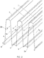
- the schematic view shown in figure 2 of a sheet 4 provided with a profile shows the multiple trapezium profile of sheet 4.
- the profile comprises inclining side walls 5a, 5b, upper walls 7 and lower walls 6, wherein the upper and lower walls 6, 7 extend in the main direction of sheet 4 and the inclining side walls 5 extend at an acute angle to the upper and lower walls 6, 7.
- Ducts 8 with a trapezium-shaped section are hereby formed, which are open on their underside or their upper side and thus have to be closed by another sheet. As a result of this acute angle the upper and lower walls 6, 7 are wide, which provides the option of stacking the thus formed sheets 4 without interposing flat sheets as in the prior art.
- the flow resistance of ducts 8 with a trapezium-shaped section has further been found to be considerably lower than that of the prior art triangular ducts 3.
- thermoforming for the purpose of arranging the profile in the sheets.
- a sheet is placed here on a mould provided with the desired profile, the sheet is heated and the sheet is urged against the mould by means of a difference in air pressure, so that the sheet deformable by means of heating takes on the shape of the mould.
- After shaping of the sheet it is allowed to cool, after which it retains its shape.
- the current trapezium shape makes it difficult to remove the formed sheet from the mould, since the combination is not self-releasing.
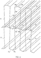
- the upper wall of the sheet is provided with a fold.
- Such a sheet provided with a fold is shown in figure 3 .
- Upper wall 6 is divided into two equal parts 6a and 6b by fold 9. During removal of the sheet from the mould the upper wall can fold at the fold so that the part protruding into the cavity of the mould can be made narrower and can be removed from the mould.
- lower wall 7 is also provided with a fold 10 which divides lower wall 7 into two equal parts 7a and 7b. This fold has no function in the removal of the formed sheet from the mould, but fold 10 does have a function during stacking, as will be elucidated below.
- the first stacking method is shown in figure 4 .
- the sheets are stacked with the lower wall of the duct of an upper-lying sheet above the upper wall of the ducts of the underlying sheet.
- the result thereof is that assembled ducts are obtained with a height double that of the ducts in a single sheet.
- a significant advantage of this embodiment is that lower wall 7 of upper-lying sheet 4 rests on the single upper wall 6 of underlying sheet 4, wherein both sheets are provided with a fold which makes the relevant walls fit into each other, whereby the sheets are mutually fixed. It is noted here that folds 9, 10 in lower and upper walls 6, 7 do have to point in the same direction in order to achieve this effect.
- the relatively great height of the assembled duct 3 only has the effect that thermal energy is exchanged via the side walls. Since the upper and lower walls 6, 7 are quite narrow, this is only a small drawback. It is noted that in the shown embodiment the sheets have a profile in the form of an acute-angled trapezium, which has the result that the section of the combined duct is constricted. Not precluded however is that the profile of the sheets is obtuse-angled and the assembled duct widens in the centre. When the assembled profile narrows in the centre it is then recommended that the width of the duct is about 80% of the maximum width of the duct.
- ducts 3 are bounded on their underside by those parts of upper wall 6 of underlying sheet 4 which do not function as support for the lower wall of sheet 4 in which ducts 3 extend.
- Another difference from the stacking shown in figure 4 is the fact that the folds 9, 10 in the lower and upper surfaces 6, 7 are directed outward in order to obtain the required stability of the stacking; in the stacking method shown in figure 3 the fold 10 in lower surface 7 is directed inward and the fold 9 in upper surface 6 is directed outward.
- Figure 6 shows a cross-section of a profile of a sheet 4 as currently envisaged; this relates particularly to the ratio between height and width of duct 3.
- the ratio of the average height and the average width of the profile is 4.25, although it is likewise possible to apply other ratios in the range between 4 and 5 or between 3 and 6.
- the ratio of the widest part of the duct and the narrowest part amounts to about 1.2, although it is likewise possible to make use of other ratios between 1.1 and 1.4 or between 1.05 and 1.5.
- Figure 7 shows a cross-section of a mould 20 applied for the purpose of arranging the profile in the sheets.
- the mould is provided for this purpose with a number of grooves 21, the profile of which corresponds to the profile of the ducts to be formed in the sheet.
- the grooves are provided with side walls 22 tapering to the outside and with an end wall 24 divided into two parts 24a, 24b by a fold 23.
- Formed between grooves 21 are intermediate surfaces 25 which are divided into two parts 25a, 25b by a fold 26.
- the grooves and intermediate surfaces preferably take a symmetrical form.
- Figure 8 shows a cross-section of mould 20 in combination with a counter-mould 30.
- Counter-mould 30 is provided with elongate protrusions 31 which can move into grooves 21 of mould 20.
- Protrusions 31 are provided with two outward tapering side walls 32 ending in a head part provided with four end surfaces 33a, 33b, 33c and 33d.
- Also arranged in intermediate surfaces 34 between protrusions 31 is a fold 35 which divides intermediate surfaces 34 into two equal parts 34a and 34b. Because side walls 32 of protrusions 31 and side walls 22 of grooves 21 taper in opposite direction, space which is used during the thermoforming is created between grooves 21 and protrusions 31 when protrusions 31 are moved into grooves 21.
- a medium such as air.
- air ducts arranged in mould 20 or in counter-mould 30.
- a main air duct 28 extending transversely of the main plane of the mould and of the sheet to be formed is arranged in each of the parts 27 between grooves 21, which air duct is provided with a number of side air ducts 29 debouching in side walls 22 of grooves 21.
- a main air duct 36 extending transversely of the main plane of the mould is arranged in each of the protrusions, from which air duct branch off a number of side air ducts 37 which debouch in side walls 32.
- the main air ducts 28, 36 are each connected to a pump not shown in the drawing.
- thermoforming device comprising mould 20 and counter-mould 30
- Mould 20 and counter-mould 30 are initially moved apart and the sheet 4 to be deformed is placed between mould 20 and counter-mould 30.
- Sheet 4 is heated prior to placing, although it is likewise possible for sheet 4 to be heated between mould 20 and counter-mould 30.
- heated air is then carried against sheet 4 from the side air ducts 37 arranged in counter-mould 30.
- Sheet 4 is hereby heated further and the sheet is pressed against mould 20, wherein sheet 4 is made deformable owing to its high temperature and takes on the shape of mould 20.
- sheet 4 and counter-mould 30 is cooled by per se known thermal ducts (not shown in the drawing) which are present in mould 20 and counter-mould 30 and with which the mould and the counter-mould can also be heated.
- counter-mould 30 is once again moved away from mould 20 and air is blown from side air ducts 29 into mould 20, which air presses toward each other the side walls 5 formed during the process of forming ducts 3 in sheets 4 so that the shaped sheet 4 can be removed.
- Fold 9 in upper wall 6 of ducts 3 here facilitates movement toward each other of side walls 5 of ducts 3.
- Figures 9 and 10 show the angle of protrusion 31 of counter-mould 30, i.e. the four-part end wall 33a, 33b, 33c and 33d thereof, in combination with a part of the deforming sheet 4 during the above elucidated process.
- Figure 9 shows here the situation in which protrusion 31 presses fold 9 of upper wall 6 into fold 23 of end wall 24 of groove 21. It can be seen how the two end surfaces 33b, 33c are in contact with the upper wall 6 of the profile formed from sheet 4.
- protrusion 31 of counter-mould 30 retracts from groove 21.
Landscapes
- Engineering & Computer Science (AREA)
- Mechanical Engineering (AREA)
- Physics & Mathematics (AREA)
- Thermal Sciences (AREA)
- General Engineering & Computer Science (AREA)
- Heat-Exchange Devices With Radiators And Conduit Assemblies (AREA)
Claims (4)
- Wärmetauscher, der mehrere Platten (1, 4) umfasst, die aufeinandergestapelt sind und sich parallel zueinander erstrecken,
wobei zumindest einige der mehreren Platten (4) über zumindest einen Teil ihrer Fläche mit Profilen versehen sind, die Kanäle (8) bilden, die sich zwischen den Platten erstrecken, wobei sich die auf beiden Seiten einer Platte vorhandenen Kanäle parallel erstrecken und wobei die Profile obere und untere Wände (6, 7) aufweisen, die sich parallel zur Hauptebene der Platten (1 ,4) erstrecken;
wobei jede der Platten (1, 4) auf einer ihrer Seiten an Kanäle (8) einer ersten Art angrenzt und auf der anderen Seite an Kanäle (8) einer zweiten Art angrenzt;
wobei angrenzende, aufeinandergestapelte Platten (1, 4) an ihren Kanten, die sich parallel zu den Kanälen (8) erstrecken, miteinander verbunden sind;
wobei alle Platten (4) mit einem Profil versehen sind und sich das Profil jeder Platte (4) über die gesamte Fläche des Wärmetauschers erstreckt;
wobei die durchschnittliche Höhe der Kanäle (8) größer als ihre durchschnittliche Breite ist,
wobei die Platten (4) mit den unteren Wänden (7) einer darüber liegenden Platte (4) über den oberen Wänden (6) der darunterliegenden Platte (4) gestapelt sind;
wobei die Profilanordnung in den Platten (4) und die Form der Kanäle (8) eine sich wiederholende Trapezform aufweist,
dadurch gekennzeichnet, dass die Platten (4) sowohl auf ihrer oberen als auch unteren Wand (6, 7) einen Falz (9, 10) aufweisen, der sich parallel zur Hauptebene der Platten (1, 4) erstreckt, wobei sich die Falze (9) in den oberen Wänden (7) in dieselbe Richtung erstrecken wie die Falze (10) in den unteren Wänden (7) und wobei der Falz (9) einer oberen Wand (6) einer darunterliegenden Platte (4) in den Falz (10) einer unteren Wand (7) einer darüber liegenden Platte passt. - Wärmetauscher nach Anspruch 1, dadurch gekennzeichnet, dass die Winkel zwischen den Seitenwänden (5a, 5b) der Kanäle (8) die einen Teil einer einzelnen Platte (4) bilden, spitz sind.
- Wärmetauscher nach Anspruch 2, dadurch gekennzeichnet, dass die montierten Kanäle (8), die von zwei verbundenen Platten (4) umschlossen werden, eine Verengung in der Mitte aufweisen und dass die Verengung der Kanäle kleiner als 20 % der Maximalbreite des Kanals ist.
- Wärmetauscher nach einem der vorstehenden Ansprüche, dadurch gekennzeichnet, dass die Platten (1, 4) aus über einen Thermoformprozess verformbare Kunststoffplatten gefertigt sind.
Priority Applications (1)
| Application Number | Priority Date | Filing Date | Title |
|---|---|---|---|
| PL14781319T PL3047223T3 (pl) | 2013-09-17 | 2014-09-10 | Wymiennik ciepła o udoskonalonej konfiguracji |
Applications Claiming Priority (2)
| Application Number | Priority Date | Filing Date | Title |
|---|---|---|---|
| NL2011454A NL2011454C2 (nl) | 2013-09-17 | 2013-09-17 | Warmtewisselaar met verbeterde geometrie. |
| PCT/NL2014/050618 WO2015041518A2 (en) | 2013-09-17 | 2014-09-10 | Heat exchanger with improved configuration |
Publications (2)
| Publication Number | Publication Date |
|---|---|
| EP3047223A2 EP3047223A2 (de) | 2016-07-27 |
| EP3047223B1 true EP3047223B1 (de) | 2019-11-06 |
Family
ID=49775687
Family Applications (1)
| Application Number | Title | Priority Date | Filing Date |
|---|---|---|---|
| EP14781319.0A Active EP3047223B1 (de) | 2013-09-17 | 2014-09-10 | Wärmetauscher mit verbesserter konfiguration |
Country Status (11)
| Country | Link |
|---|---|
| US (1) | US20160223273A1 (de) |
| EP (1) | EP3047223B1 (de) |
| JP (1) | JP2016534316A (de) |
| KR (1) | KR20160058123A (de) |
| CN (1) | CN105659047A (de) |
| CA (1) | CA2922840A1 (de) |
| DK (1) | DK3047223T3 (de) |
| ES (1) | ES2771351T3 (de) |
| NL (1) | NL2011454C2 (de) |
| PL (1) | PL3047223T3 (de) |
| WO (1) | WO2015041518A2 (de) |
Families Citing this family (4)
| Publication number | Priority date | Publication date | Assignee | Title |
|---|---|---|---|---|
| NL2016731B1 (nl) | 2016-05-03 | 2017-11-10 | Recair Holding B V | Inrichting voor het uitwisselen van energie tussen twee luchtstromen. |
| CN110756670A (zh) * | 2019-11-04 | 2020-02-07 | 中国航空制造技术研究院 | 一种热成形模具 |
| NL2026943B1 (nl) * | 2020-11-20 | 2022-07-01 | Level Holding Ii B V | Recuperator met verbeterde kanaalconfiguratie |
| EP4644231A1 (de) * | 2024-05-02 | 2025-11-05 | Airbus (S.A.S.) | Flugzeugstrukturbauteil mit einem als wärmetauscher ausgebildeten faltkern-sandwichelement |
Family Cites Families (23)
| Publication number | Priority date | Publication date | Assignee | Title |
|---|---|---|---|---|
| US2595457A (en) * | 1947-06-03 | 1952-05-06 | Air Preheater | Pin fin heat exchanger |
| US2703921A (en) * | 1949-04-14 | 1955-03-15 | Brown Fintube Co | Method of making internally finned tubes |
| US2782009A (en) * | 1952-03-14 | 1957-02-19 | Gen Motors Corp | Heat exchangers |
| FR1245012A (fr) * | 1959-09-25 | 1960-11-04 | Soudure Autogene Francaise | échangeur de chaleur à circulation parallèle des fluides |
| NL7512632A (nl) * | 1975-10-29 | 1977-05-03 | Philips Nv | Werkwijze voor het vervaardigen van een radia- teur alsmede een radiateur vervaardigd volgens die werkwijze. |
| US4411310A (en) * | 1978-04-07 | 1983-10-25 | The Boeing Company | Heat exchange apparatus having thin film flexible sheets |
| GB2158569A (en) * | 1984-05-01 | 1985-11-13 | Univ Birmingham | A gas-to-gas heat exchanger |
| DD243089A1 (de) * | 1985-11-28 | 1987-02-18 | Bitterfeld Chemie | Waermetauscher aus uebereinanderliegenden profilblechen mit trapezprofil |
| DD243088B5 (de) * | 1985-11-28 | 1995-01-26 | Eberhard Paul | Kanalwaermetauscher mit variierbarer Waermetauschflaeche |
| CN2097998U (zh) * | 1991-07-15 | 1992-03-04 | 沈阳黎明发动机制造公司工程机械厂 | 高效不等截面板式换热器 |
| DE4333904C2 (de) * | 1993-09-27 | 1996-02-22 | Eberhard Dipl Ing Paul | Kanalwärmetauscher |
| US5511610A (en) * | 1994-03-15 | 1996-04-30 | Behr Heat Transfer Systems | Off-set louvered heat exchanger fin and method for making same |
| DE19635552C1 (de) * | 1996-09-02 | 1998-03-12 | Slg Pruef Und Zertifizierungs | Wärmetauscher |
| FR2781387B1 (fr) * | 1998-07-24 | 2000-09-15 | Eau De Nancy Nan C I E Centre | Procede pour la distillation d'un fluide a transfert horizontal de vapeur dans la zone de condensation et dispositif modulaire de mise en oeuvre du procede |
| GB0023427D0 (en) * | 2000-09-23 | 2000-11-08 | Smiths Industries Plc | Apparatus |
| DE10213543A1 (de) * | 2001-11-30 | 2003-06-12 | Hartmut Koenig | Wärmeübertrager für gasförmige Medien |
| DE10329153B4 (de) * | 2003-06-27 | 2006-04-20 | Paul, Eberhard, Dipl.-Ing. | Wärmeübertragerplatine |
| DE102004055550A1 (de) * | 2004-11-17 | 2006-05-24 | Kwm Weisshaar Blechbearbeitung Gmbh | Wärmetauscher |
| FR2897930B1 (fr) * | 2006-02-28 | 2008-05-16 | Commissariat Energie Atomique | Echangeur thermique a plaques incluant un dispositif d'evaluation de son etat d'encrassement |
| WO2008128235A1 (en) * | 2007-04-16 | 2008-10-23 | Celltech Metals, Inc. | Flow-through sandwich core structure and method and system for same |
| JP4994450B2 (ja) * | 2007-06-18 | 2012-08-08 | 三菱電機株式会社 | 熱交換素子およびその製造方法ならびに熱交換器および熱交換換気装置 |
| FR2955796B1 (fr) * | 2010-02-01 | 2012-05-25 | Hamon Thermal Europ France | Dispositif de soudage par ultrasons, notamment pour le soudage d'un empilement de feuilles alveolees |
| JP5244845B2 (ja) * | 2010-03-31 | 2013-07-24 | 株式会社ユタカ技研 | 熱交換器 |
-
2013
- 2013-09-17 NL NL2011454A patent/NL2011454C2/nl not_active IP Right Cessation
-
2014
- 2014-09-10 DK DK14781319.0T patent/DK3047223T3/da active
- 2014-09-10 JP JP2016542659A patent/JP2016534316A/ja active Pending
- 2014-09-10 WO PCT/NL2014/050618 patent/WO2015041518A2/en not_active Ceased
- 2014-09-10 CN CN201480051290.0A patent/CN105659047A/zh active Pending
- 2014-09-10 EP EP14781319.0A patent/EP3047223B1/de active Active
- 2014-09-10 PL PL14781319T patent/PL3047223T3/pl unknown
- 2014-09-10 CA CA2922840A patent/CA2922840A1/en not_active Abandoned
- 2014-09-10 KR KR1020167008908A patent/KR20160058123A/ko not_active Withdrawn
- 2014-09-10 ES ES14781319T patent/ES2771351T3/es active Active
- 2014-09-10 US US15/022,365 patent/US20160223273A1/en not_active Abandoned
Non-Patent Citations (1)
| Title |
|---|
| None * |
Also Published As
| Publication number | Publication date |
|---|---|
| CN105659047A (zh) | 2016-06-08 |
| US20160223273A1 (en) | 2016-08-04 |
| NL2011454C2 (nl) | 2015-03-18 |
| CA2922840A1 (en) | 2015-03-26 |
| KR20160058123A (ko) | 2016-05-24 |
| JP2016534316A (ja) | 2016-11-04 |
| PL3047223T3 (pl) | 2020-06-01 |
| WO2015041518A3 (en) | 2015-08-13 |
| ES2771351T3 (es) | 2020-07-06 |
| DK3047223T3 (da) | 2020-02-17 |
| WO2015041518A2 (en) | 2015-03-26 |
| EP3047223A2 (de) | 2016-07-27 |
Similar Documents
| Publication | Publication Date | Title |
|---|---|---|
| EP3047223B1 (de) | Wärmetauscher mit verbesserter konfiguration | |
| CN101307995B (zh) | 用于气态介质的热交换器 | |
| CA2999660C (en) | Stacked plate heat exchanger with form fitting connection of the plates | |
| JP6892099B2 (ja) | 積層構造体の製造方法 | |
| EP3040639B1 (de) | Strahlungsrippe mit gekrümmten abstrahlungsabschnitt und elektrothermische ölheizung damit | |
| KR101287707B1 (ko) | 열교환관 및 그 제조방법 | |
| JP2017507312A (ja) | プレート式熱交換器のための熱交換プレートおよび前記熱交換プレートが設けられたプレート式熱交換器 | |
| JP6139921B2 (ja) | 熱交換素子 | |
| JP2000153551A (ja) | 熱伝達プレ―ト及び熱伝達プレ―トの製造方法 | |
| JP6734365B2 (ja) | ジェットボックスおよびそれを用いた乾燥機 | |
| EP3648941B1 (de) | Vorrichtung und verfahren zur herstellung eines plattenförmigen geschäumten formkunststoffprodukts | |
| JP2017514096A (ja) | チューブのコアを備える熱交換器 | |
| ITTO980737A1 (it) | Scambiatori di calore a flussi incrociati per asciugabiancheria a con- densazione. | |
| KR101579540B1 (ko) | 열교환 효율이 향상된 마이크로 가스터빈을 위한 주전열면을 구비한 열교환판, 및 이를 이용한 열교환기 | |
| ES3035992T3 (en) | Recuperator, parts of which are manufactured by injection moulding | |
| WO2018157192A1 (en) | Heat exchanger | |
| JP2018044707A (ja) | 熱交換器 | |
| CN211959592U (zh) | 铲翅片陶瓷ptc电加热器 | |
| CN210773543U (zh) | 一种叠合散热器 | |
| JP4606097B2 (ja) | 成形用金型 | |
| CN205040046U (zh) | 一种密集型正温度系数热敏电阻加热器 | |
| KR101370131B1 (ko) | 열교환기용 열판 및 그 제조방법 | |
| JP6534336B2 (ja) | ダクト及びダクトの製造方法 | |
| US1316636A (en) | Method of forming sheet metal. | |
| CN209942020U (zh) | 一种拼装式eps建筑空腔模块 |
Legal Events
| Date | Code | Title | Description |
|---|---|---|---|
| PUAI | Public reference made under article 153(3) epc to a published international application that has entered the european phase |
Free format text: ORIGINAL CODE: 0009012 |
|
| 17P | Request for examination filed |
Effective date: 20160418 |
|
| AK | Designated contracting states |
Kind code of ref document: A2 Designated state(s): AL AT BE BG CH CY CZ DE DK EE ES FI FR GB GR HR HU IE IS IT LI LT LU LV MC MK MT NL NO PL PT RO RS SE SI SK SM TR |
|
| AX | Request for extension of the european patent |
Extension state: BA ME |
|
| DAX | Request for extension of the european patent (deleted) | ||
| STAA | Information on the status of an ep patent application or granted ep patent |
Free format text: STATUS: EXAMINATION IS IN PROGRESS |
|
| 17Q | First examination report despatched |
Effective date: 20170721 |
|
| TPAC | Observations filed by third parties |
Free format text: ORIGINAL CODE: EPIDOSNTIPA |
|
| TPAC | Observations filed by third parties |
Free format text: ORIGINAL CODE: EPIDOSNTIPA |
|
| GRAP | Despatch of communication of intention to grant a patent |
Free format text: ORIGINAL CODE: EPIDOSNIGR1 |
|
| STAA | Information on the status of an ep patent application or granted ep patent |
Free format text: STATUS: GRANT OF PATENT IS INTENDED |
|
| INTG | Intention to grant announced |
Effective date: 20190603 |
|
| GRAS | Grant fee paid |
Free format text: ORIGINAL CODE: EPIDOSNIGR3 |
|
| GRAA | (expected) grant |
Free format text: ORIGINAL CODE: 0009210 |
|
| STAA | Information on the status of an ep patent application or granted ep patent |
Free format text: STATUS: THE PATENT HAS BEEN GRANTED |
|
| AK | Designated contracting states |
Kind code of ref document: B1 Designated state(s): AL AT BE BG CH CY CZ DE DK EE ES FI FR GB GR HR HU IE IS IT LI LT LU LV MC MK MT NL NO PL PT RO RS SE SI SK SM TR |
|
| REG | Reference to a national code |
Ref country code: GB Ref legal event code: FG4D |
|
| REG | Reference to a national code |
Ref country code: CH Ref legal event code: EP Ref country code: AT Ref legal event code: REF Ref document number: 1199308 Country of ref document: AT Kind code of ref document: T Effective date: 20191115 |
|
| REG | Reference to a national code |
Ref country code: DE Ref legal event code: R096 Ref document number: 602014056365 Country of ref document: DE |
|
| REG | Reference to a national code |
Ref country code: IE Ref legal event code: FG4D |
|
| REG | Reference to a national code |
Ref country code: CH Ref legal event code: NV Representative=s name: BOHEST AG, CH |
|
| REG | Reference to a national code |
Ref country code: DK Ref legal event code: T3 Effective date: 20200211 |
|
| REG | Reference to a national code |
Ref country code: NL Ref legal event code: FP |
|
| REG | Reference to a national code |
Ref country code: LT Ref legal event code: MG4D |
|
| PG25 | Lapsed in a contracting state [announced via postgrant information from national office to epo] |
Ref country code: LT Free format text: LAPSE BECAUSE OF FAILURE TO SUBMIT A TRANSLATION OF THE DESCRIPTION OR TO PAY THE FEE WITHIN THE PRESCRIBED TIME-LIMIT Effective date: 20191106 Ref country code: BG Free format text: LAPSE BECAUSE OF FAILURE TO SUBMIT A TRANSLATION OF THE DESCRIPTION OR TO PAY THE FEE WITHIN THE PRESCRIBED TIME-LIMIT Effective date: 20200206 Ref country code: FI Free format text: LAPSE BECAUSE OF FAILURE TO SUBMIT A TRANSLATION OF THE DESCRIPTION OR TO PAY THE FEE WITHIN THE PRESCRIBED TIME-LIMIT Effective date: 20191106 Ref country code: SE Free format text: LAPSE BECAUSE OF FAILURE TO SUBMIT A TRANSLATION OF THE DESCRIPTION OR TO PAY THE FEE WITHIN THE PRESCRIBED TIME-LIMIT Effective date: 20191106 Ref country code: LV Free format text: LAPSE BECAUSE OF FAILURE TO SUBMIT A TRANSLATION OF THE DESCRIPTION OR TO PAY THE FEE WITHIN THE PRESCRIBED TIME-LIMIT Effective date: 20191106 Ref country code: NO Free format text: LAPSE BECAUSE OF FAILURE TO SUBMIT A TRANSLATION OF THE DESCRIPTION OR TO PAY THE FEE WITHIN THE PRESCRIBED TIME-LIMIT Effective date: 20200206 Ref country code: GR Free format text: LAPSE BECAUSE OF FAILURE TO SUBMIT A TRANSLATION OF THE DESCRIPTION OR TO PAY THE FEE WITHIN THE PRESCRIBED TIME-LIMIT Effective date: 20200207 Ref country code: PT Free format text: LAPSE BECAUSE OF FAILURE TO SUBMIT A TRANSLATION OF THE DESCRIPTION OR TO PAY THE FEE WITHIN THE PRESCRIBED TIME-LIMIT Effective date: 20200306 |
|
| PG25 | Lapsed in a contracting state [announced via postgrant information from national office to epo] |
Ref country code: RS Free format text: LAPSE BECAUSE OF FAILURE TO SUBMIT A TRANSLATION OF THE DESCRIPTION OR TO PAY THE FEE WITHIN THE PRESCRIBED TIME-LIMIT Effective date: 20191106 Ref country code: HR Free format text: LAPSE BECAUSE OF FAILURE TO SUBMIT A TRANSLATION OF THE DESCRIPTION OR TO PAY THE FEE WITHIN THE PRESCRIBED TIME-LIMIT Effective date: 20191106 Ref country code: IS Free format text: LAPSE BECAUSE OF FAILURE TO SUBMIT A TRANSLATION OF THE DESCRIPTION OR TO PAY THE FEE WITHIN THE PRESCRIBED TIME-LIMIT Effective date: 20200306 |
|
| PG25 | Lapsed in a contracting state [announced via postgrant information from national office to epo] |
Ref country code: AL Free format text: LAPSE BECAUSE OF FAILURE TO SUBMIT A TRANSLATION OF THE DESCRIPTION OR TO PAY THE FEE WITHIN THE PRESCRIBED TIME-LIMIT Effective date: 20191106 |
|
| REG | Reference to a national code |
Ref country code: ES Ref legal event code: FG2A Ref document number: 2771351 Country of ref document: ES Kind code of ref document: T3 Effective date: 20200706 |
|
| PG25 | Lapsed in a contracting state [announced via postgrant information from national office to epo] |
Ref country code: RO Free format text: LAPSE BECAUSE OF FAILURE TO SUBMIT A TRANSLATION OF THE DESCRIPTION OR TO PAY THE FEE WITHIN THE PRESCRIBED TIME-LIMIT Effective date: 20191106 Ref country code: EE Free format text: LAPSE BECAUSE OF FAILURE TO SUBMIT A TRANSLATION OF THE DESCRIPTION OR TO PAY THE FEE WITHIN THE PRESCRIBED TIME-LIMIT Effective date: 20191106 |
|
| REG | Reference to a national code |
Ref country code: DE Ref legal event code: R097 Ref document number: 602014056365 Country of ref document: DE |
|
| REG | Reference to a national code |
Ref country code: AT Ref legal event code: MK05 Ref document number: 1199308 Country of ref document: AT Kind code of ref document: T Effective date: 20191106 |
|
| PG25 | Lapsed in a contracting state [announced via postgrant information from national office to epo] |
Ref country code: SK Free format text: LAPSE BECAUSE OF FAILURE TO SUBMIT A TRANSLATION OF THE DESCRIPTION OR TO PAY THE FEE WITHIN THE PRESCRIBED TIME-LIMIT Effective date: 20191106 Ref country code: SM Free format text: LAPSE BECAUSE OF FAILURE TO SUBMIT A TRANSLATION OF THE DESCRIPTION OR TO PAY THE FEE WITHIN THE PRESCRIBED TIME-LIMIT Effective date: 20191106 |
|
| PLBE | No opposition filed within time limit |
Free format text: ORIGINAL CODE: 0009261 |
|
| STAA | Information on the status of an ep patent application or granted ep patent |
Free format text: STATUS: NO OPPOSITION FILED WITHIN TIME LIMIT |
|
| 26N | No opposition filed |
Effective date: 20200807 |
|
| PG25 | Lapsed in a contracting state [announced via postgrant information from national office to epo] |
Ref country code: AT Free format text: LAPSE BECAUSE OF FAILURE TO SUBMIT A TRANSLATION OF THE DESCRIPTION OR TO PAY THE FEE WITHIN THE PRESCRIBED TIME-LIMIT Effective date: 20191106 Ref country code: SI Free format text: LAPSE BECAUSE OF FAILURE TO SUBMIT A TRANSLATION OF THE DESCRIPTION OR TO PAY THE FEE WITHIN THE PRESCRIBED TIME-LIMIT Effective date: 20191106 |
|
| REG | Reference to a national code |
Ref country code: BE Ref legal event code: QB Free format text: DETAILS LICENCE: LICENCE, NEW LICENCE REGISTRATION Name of requester: VERO DUCO NV Effective date: 20220214 |
|
| REG | Reference to a national code |
Ref country code: NL Ref legal event code: QB Free format text: DETAILS LICENCE OR PLEDGE: LICENCE, NEW LICENCE REGISTRATION Name of requester: VERO DUCO NV Effective date: 20220215 |
|
| PG25 | Lapsed in a contracting state [announced via postgrant information from national office to epo] |
Ref country code: TR Free format text: LAPSE BECAUSE OF FAILURE TO SUBMIT A TRANSLATION OF THE DESCRIPTION OR TO PAY THE FEE WITHIN THE PRESCRIBED TIME-LIMIT Effective date: 20191106 Ref country code: MT Free format text: LAPSE BECAUSE OF FAILURE TO SUBMIT A TRANSLATION OF THE DESCRIPTION OR TO PAY THE FEE WITHIN THE PRESCRIBED TIME-LIMIT Effective date: 20191106 Ref country code: CY Free format text: LAPSE BECAUSE OF FAILURE TO SUBMIT A TRANSLATION OF THE DESCRIPTION OR TO PAY THE FEE WITHIN THE PRESCRIBED TIME-LIMIT Effective date: 20191106 |
|
| PG25 | Lapsed in a contracting state [announced via postgrant information from national office to epo] |
Ref country code: MK Free format text: LAPSE BECAUSE OF FAILURE TO SUBMIT A TRANSLATION OF THE DESCRIPTION OR TO PAY THE FEE WITHIN THE PRESCRIBED TIME-LIMIT Effective date: 20191106 |
|
| REG | Reference to a national code |
Ref country code: CH Ref legal event code: U11 Free format text: ST27 STATUS EVENT CODE: U-0-0-U10-U11 (AS PROVIDED BY THE NATIONAL OFFICE) Effective date: 20251001 |
|
| PGFP | Annual fee paid to national office [announced via postgrant information from national office to epo] |
Ref country code: DK Payment date: 20250925 Year of fee payment: 12 Ref country code: DE Payment date: 20250929 Year of fee payment: 12 |
|
| PGFP | Annual fee paid to national office [announced via postgrant information from national office to epo] |
Ref country code: MC Payment date: 20250821 Year of fee payment: 12 |
|
| PGFP | Annual fee paid to national office [announced via postgrant information from national office to epo] |
Ref country code: PL Payment date: 20250821 Year of fee payment: 12 Ref country code: NL Payment date: 20250926 Year of fee payment: 12 Ref country code: IT Payment date: 20250919 Year of fee payment: 12 Ref country code: LU Payment date: 20250929 Year of fee payment: 12 |
|
| PGFP | Annual fee paid to national office [announced via postgrant information from national office to epo] |
Ref country code: BE Payment date: 20250929 Year of fee payment: 12 Ref country code: GB Payment date: 20250929 Year of fee payment: 12 |
|
| PGFP | Annual fee paid to national office [announced via postgrant information from national office to epo] |
Ref country code: FR Payment date: 20250925 Year of fee payment: 12 |
|
| PGFP | Annual fee paid to national office [announced via postgrant information from national office to epo] |
Ref country code: IE Payment date: 20250929 Year of fee payment: 12 Ref country code: CZ Payment date: 20250826 Year of fee payment: 12 |
|
| PGFP | Annual fee paid to national office [announced via postgrant information from national office to epo] |
Ref country code: CH Payment date: 20251001 Year of fee payment: 12 |
|
| PGFP | Annual fee paid to national office [announced via postgrant information from national office to epo] |
Ref country code: ES Payment date: 20251001 Year of fee payment: 12 |