EP3040639B1 - Strahlungsrippe mit gekrümmten abstrahlungsabschnitt und elektrothermische ölheizung damit - Google Patents
Strahlungsrippe mit gekrümmten abstrahlungsabschnitt und elektrothermische ölheizung damit Download PDFInfo
- Publication number
- EP3040639B1 EP3040639B1 EP15198325.1A EP15198325A EP3040639B1 EP 3040639 B1 EP3040639 B1 EP 3040639B1 EP 15198325 A EP15198325 A EP 15198325A EP 3040639 B1 EP3040639 B1 EP 3040639B1
- Authority
- EP
- European Patent Office
- Prior art keywords
- bent
- radiating
- radiating portion
- radiating fin
- fin
- Prior art date
- Legal status (The legal status is an assumption and is not a legal conclusion. Google has not performed a legal analysis and makes no representation as to the accuracy of the status listed.)
- Not-in-force
Links
Images





Classifications
-
- F—MECHANICAL ENGINEERING; LIGHTING; HEATING; WEAPONS; BLASTING
- F28—HEAT EXCHANGE IN GENERAL
- F28F—DETAILS OF HEAT-EXCHANGE AND HEAT-TRANSFER APPARATUS, OF GENERAL APPLICATION
- F28F3/00—Plate-like or laminated elements; Assemblies of plate-like or laminated elements
- F28F3/02—Elements or assemblies thereof with means for increasing heat-transfer area, e.g. with fins, with recesses, with corrugations
- F28F3/06—Elements or assemblies thereof with means for increasing heat-transfer area, e.g. with fins, with recesses, with corrugations the means being attachable to the element
-
- F—MECHANICAL ENGINEERING; LIGHTING; HEATING; WEAPONS; BLASTING
- F24—HEATING; RANGES; VENTILATING
- F24H—FLUID HEATERS, e.g. WATER OR AIR HEATERS, HAVING HEAT-GENERATING MEANS, e.g. HEAT PUMPS, IN GENERAL
- F24H3/00—Air heaters
- F24H3/002—Air heaters using electric energy supply
- F24H3/004—Air heaters using electric energy supply with a closed circuit for a heat transfer liquid
-
- F—MECHANICAL ENGINEERING; LIGHTING; HEATING; WEAPONS; BLASTING
- F28—HEAT EXCHANGE IN GENERAL
- F28D—HEAT-EXCHANGE APPARATUS, NOT PROVIDED FOR IN ANOTHER SUBCLASS, IN WHICH THE HEAT-EXCHANGE MEDIA DO NOT COME INTO DIRECT CONTACT
- F28D1/00—Heat-exchange apparatus having stationary conduit assemblies for one heat-exchange medium only, the media being in contact with different sides of the conduit wall, in which the other heat-exchange medium is a large body of fluid, e.g. domestic or motor car radiators
- F28D1/02—Heat-exchange apparatus having stationary conduit assemblies for one heat-exchange medium only, the media being in contact with different sides of the conduit wall, in which the other heat-exchange medium is a large body of fluid, e.g. domestic or motor car radiators with heat-exchange conduits immersed in the body of fluid
- F28D1/03—Heat-exchange apparatus having stationary conduit assemblies for one heat-exchange medium only, the media being in contact with different sides of the conduit wall, in which the other heat-exchange medium is a large body of fluid, e.g. domestic or motor car radiators with heat-exchange conduits immersed in the body of fluid with plate-like or laminated conduits
- F28D1/0308—Heat-exchange apparatus having stationary conduit assemblies for one heat-exchange medium only, the media being in contact with different sides of the conduit wall, in which the other heat-exchange medium is a large body of fluid, e.g. domestic or motor car radiators with heat-exchange conduits immersed in the body of fluid with plate-like or laminated conduits the conduits being formed by paired plates touching each other
- F28D1/0325—Heat-exchange apparatus having stationary conduit assemblies for one heat-exchange medium only, the media being in contact with different sides of the conduit wall, in which the other heat-exchange medium is a large body of fluid, e.g. domestic or motor car radiators with heat-exchange conduits immersed in the body of fluid with plate-like or laminated conduits the conduits being formed by paired plates touching each other the plates having lateral openings therein for circulation of the heat-exchange medium from one conduit to another
- F28D1/0333—Heat-exchange apparatus having stationary conduit assemblies for one heat-exchange medium only, the media being in contact with different sides of the conduit wall, in which the other heat-exchange medium is a large body of fluid, e.g. domestic or motor car radiators with heat-exchange conduits immersed in the body of fluid with plate-like or laminated conduits the conduits being formed by paired plates touching each other the plates having lateral openings therein for circulation of the heat-exchange medium from one conduit to another the plates having integrated connecting members
-
- F—MECHANICAL ENGINEERING; LIGHTING; HEATING; WEAPONS; BLASTING
- F28—HEAT EXCHANGE IN GENERAL
- F28D—HEAT-EXCHANGE APPARATUS, NOT PROVIDED FOR IN ANOTHER SUBCLASS, IN WHICH THE HEAT-EXCHANGE MEDIA DO NOT COME INTO DIRECT CONTACT
- F28D1/00—Heat-exchange apparatus having stationary conduit assemblies for one heat-exchange medium only, the media being in contact with different sides of the conduit wall, in which the other heat-exchange medium is a large body of fluid, e.g. domestic or motor car radiators
- F28D1/02—Heat-exchange apparatus having stationary conduit assemblies for one heat-exchange medium only, the media being in contact with different sides of the conduit wall, in which the other heat-exchange medium is a large body of fluid, e.g. domestic or motor car radiators with heat-exchange conduits immersed in the body of fluid
- F28D1/04—Heat-exchange apparatus having stationary conduit assemblies for one heat-exchange medium only, the media being in contact with different sides of the conduit wall, in which the other heat-exchange medium is a large body of fluid, e.g. domestic or motor car radiators with heat-exchange conduits immersed in the body of fluid with tubular conduits
- F28D1/053—Heat-exchange apparatus having stationary conduit assemblies for one heat-exchange medium only, the media being in contact with different sides of the conduit wall, in which the other heat-exchange medium is a large body of fluid, e.g. domestic or motor car radiators with heat-exchange conduits immersed in the body of fluid with tubular conduits the conduits being straight
- F28D1/0535—Heat-exchange apparatus having stationary conduit assemblies for one heat-exchange medium only, the media being in contact with different sides of the conduit wall, in which the other heat-exchange medium is a large body of fluid, e.g. domestic or motor car radiators with heat-exchange conduits immersed in the body of fluid with tubular conduits the conduits being straight the conduits having a non-circular cross-section
- F28D1/05358—Assemblies of conduits connected side by side or with individual headers, e.g. section type radiators
-
- F—MECHANICAL ENGINEERING; LIGHTING; HEATING; WEAPONS; BLASTING
- F28—HEAT EXCHANGE IN GENERAL
- F28F—DETAILS OF HEAT-EXCHANGE AND HEAT-TRANSFER APPARATUS, OF GENERAL APPLICATION
- F28F3/00—Plate-like or laminated elements; Assemblies of plate-like or laminated elements
- F28F3/02—Elements or assemblies thereof with means for increasing heat-transfer area, e.g. with fins, with recesses, with corrugations
- F28F3/04—Elements or assemblies thereof with means for increasing heat-transfer area, e.g. with fins, with recesses, with corrugations the means being integral with the element
- F28F3/048—Elements or assemblies thereof with means for increasing heat-transfer area, e.g. with fins, with recesses, with corrugations the means being integral with the element in the form of ribs integral with the element or local variations in thickness of the element, e.g. grooves, microchannels
-
- F—MECHANICAL ENGINEERING; LIGHTING; HEATING; WEAPONS; BLASTING
- F28—HEAT EXCHANGE IN GENERAL
- F28F—DETAILS OF HEAT-EXCHANGE AND HEAT-TRANSFER APPARATUS, OF GENERAL APPLICATION
- F28F3/00—Plate-like or laminated elements; Assemblies of plate-like or laminated elements
- F28F3/08—Elements constructed for building-up into stacks, e.g. capable of being taken apart for cleaning
- F28F3/083—Elements constructed for building-up into stacks, e.g. capable of being taken apart for cleaning capable of being taken apart
-
- F—MECHANICAL ENGINEERING; LIGHTING; HEATING; WEAPONS; BLASTING
- F28—HEAT EXCHANGE IN GENERAL
- F28F—DETAILS OF HEAT-EXCHANGE AND HEAT-TRANSFER APPARATUS, OF GENERAL APPLICATION
- F28F3/00—Plate-like or laminated elements; Assemblies of plate-like or laminated elements
- F28F3/12—Elements constructed in the shape of a hollow panel, e.g. with channels
-
- F—MECHANICAL ENGINEERING; LIGHTING; HEATING; WEAPONS; BLASTING
- F24—HEATING; RANGES; VENTILATING
- F24D—DOMESTIC- OR SPACE-HEATING SYSTEMS, e.g. CENTRAL HEATING SYSTEMS; DOMESTIC HOT-WATER SUPPLY SYSTEMS; ELEMENTS OR COMPONENTS THEREFOR
- F24D13/00—Electric heating systems
- F24D13/04—Electric heating systems using electric heating of heat-transfer fluid in separate units of the system
-
- F—MECHANICAL ENGINEERING; LIGHTING; HEATING; WEAPONS; BLASTING
- F24—HEATING; RANGES; VENTILATING
- F24D—DOMESTIC- OR SPACE-HEATING SYSTEMS, e.g. CENTRAL HEATING SYSTEMS; DOMESTIC HOT-WATER SUPPLY SYSTEMS; ELEMENTS OR COMPONENTS THEREFOR
- F24D19/00—Details
- F24D19/008—Details related to central heating radiators
-
- F—MECHANICAL ENGINEERING; LIGHTING; HEATING; WEAPONS; BLASTING
- F24—HEATING; RANGES; VENTILATING
- F24H—FLUID HEATERS, e.g. WATER OR AIR HEATERS, HAVING HEAT-GENERATING MEANS, e.g. HEAT PUMPS, IN GENERAL
- F24H3/00—Air heaters
-
- F—MECHANICAL ENGINEERING; LIGHTING; HEATING; WEAPONS; BLASTING
- F28—HEAT EXCHANGE IN GENERAL
- F28D—HEAT-EXCHANGE APPARATUS, NOT PROVIDED FOR IN ANOTHER SUBCLASS, IN WHICH THE HEAT-EXCHANGE MEDIA DO NOT COME INTO DIRECT CONTACT
- F28D1/00—Heat-exchange apparatus having stationary conduit assemblies for one heat-exchange medium only, the media being in contact with different sides of the conduit wall, in which the other heat-exchange medium is a large body of fluid, e.g. domestic or motor car radiators
- F28D1/02—Heat-exchange apparatus having stationary conduit assemblies for one heat-exchange medium only, the media being in contact with different sides of the conduit wall, in which the other heat-exchange medium is a large body of fluid, e.g. domestic or motor car radiators with heat-exchange conduits immersed in the body of fluid
- F28D1/0226—Heat-exchange apparatus having stationary conduit assemblies for one heat-exchange medium only, the media being in contact with different sides of the conduit wall, in which the other heat-exchange medium is a large body of fluid, e.g. domestic or motor car radiators with heat-exchange conduits immersed in the body of fluid with an intermediate heat-transfer medium, e.g. thermosiphon radiators
-
- F—MECHANICAL ENGINEERING; LIGHTING; HEATING; WEAPONS; BLASTING
- F28—HEAT EXCHANGE IN GENERAL
- F28D—HEAT-EXCHANGE APPARATUS, NOT PROVIDED FOR IN ANOTHER SUBCLASS, IN WHICH THE HEAT-EXCHANGE MEDIA DO NOT COME INTO DIRECT CONTACT
- F28D21/00—Heat-exchange apparatus not covered by any of the groups F28D1/00 - F28D20/00
- F28D2021/0019—Other heat exchangers for particular applications; Heat exchange systems not otherwise provided for
- F28D2021/0035—Other heat exchangers for particular applications; Heat exchange systems not otherwise provided for for domestic or space heating, e.g. heating radiators
Definitions
- the present invention relates to a radiating fin, in particular to a radiating fin with a bent radiating portion, and the present invention further relates to an electrothermal oil heater using the same.
- Oil-filled electrothermal warmers are referred to as electrothermal oil heaters now.
- the electrothermal oil heaters as environmentally friendly, noiseless and other advantages, have been widely used in the world.
- electrothermal oil heaters There are 40 million electrothermal oil heaters manufactured every year.
- Such an electrothermal oil heater is generally assembled by a plurality of radiating fins, with gaps formed between the radiating fins, connected to each other via hollow connecting sleeves at an upper end and a lower end of the radiating fins.
- An electrical heating assembly is immersed in the heat transfer oil, and energy is transferred by heating the heat transfer oil.
- GB07403A A.D.1909 discloses improvements in connection with cooling devices, radiators and the like.
- sheet metal is employed, which sheet is cut to the required size preferably rectangular in shape.
- This rectangular sheet is designed to be folded over but previous to this operation approximately one half of it is rolled, impressed, or otherwise formed with a plurality of longitudinal grooves.
- One of these fluted sheets or half sheets together with a plain sheet forms the side of the special element.
- CN203785071U discloses a high-efficiency electrical oil heater which comprises a plurality of cooling units, medium storage cavities and fins, wherein the plurality of cooling units are used for diffusing heat of an oil heater body to the outside, and every two adjacent cooling units are communicated with each other; the medium storage cavities are arranged in the cooling units; each medium storage cavity is internally provided with an electric heating rod and heat conduction oil used for absorbing heat of the electric heating rod; the fins are arranged at the two sides of the cooling units and are bended towards the opposite directions.
- a radiating fin for a warmer including a radiating fin, with a hollow connecting sleeve being respectively provided on an upper portion and a lower portion of the radiating fin, characterized in that both sides of the radiating fin are flanged symmetrically.
- both sides of the radiating fin are flanged symmetrically, so that the radiating area of the radiating fin can be increased without increasing the space occupation thereof.
- the design of flanging enables formation of a chimney radiating channel between two adjacent radiating fins, thus to improve the radiating efficiency of the radiating fin.
- a technical problem to be solved by the present invention is to provide a radiating fin with a bent radiating portion, in order to overcome the aforementioned deficiencies in the prior art.
- a radiating fin allows for large radiating area and high mechanical strength, and a combined radial and convective radiating way may be realized when a plurality of the radiating fins are connected to each other to form a radiator.
- a technical problem to be solved by the present invention is to provide an electrothermal oil heater, in order to overcome the aforementioned deficiencies in the prior art.
- a bent radiating portion is formed on the radiating fin, and a combined radial and convective radiating way may be thus realized.
- the radiating fin with a bent radiating portion provided by the present invention employs the following main technical solution.
- the radiating fin includes a main body with an oil guide groove formed therein, connecting sleeves extending in a horizontal direction being provided at an upper end and a lower end of the main body; a bent radiating portion is formed within a region, a certain distance away from the middle, of an edge of at least one end of the main body; an upper end and a lower end of the bent radiating portion are located in different vertical planes, or the upper end and the lower end of the bent radiating portion are located in a same vertical plane, and at least one portion between the upper end and the lower end is bent to form a side-raised structure; and the area of the bent radiating portion is 10% to 80% of the total area of the main body.
- the radiating fin with a bent radiating portion provided by the present invention further employs the following dependent technical solution.
- the upper end and the lower end of the bent radiating portion are located in different vertical planes and connected to each other by a twisted portion, the twisted portion including two bending portions in opposite directions.
- An included angle between a plane of the upper end and a plane of the lower end is 5° to 85°.
- the upper end and the lower end of the bent radiating portion are located in a same vertical plane and connected to each other by a bent portion, the bent portion including two bending portions in a same direction.
- An included angle between a vertical projection of the upper end and the lower end and a vertical projection of the bent portion is 5° to 85°.
- a distance from an apex of the bent portion to the plane of the upper end and the lower end is 5 mm to 70 mm.
- the upper end and the lower end of the bent radiating portion are located in a same vertical plane and connected to each other by a plurality of bent portions, the bent portions each including two bending portions in a same direction.
- Two adjacent bent portions are bent in opposite directions.
- An included angle between a vertical projection of the upper end and the lower end and a vertical projection of the bent portion is 5° to 85°.
- a distance from an apex of the bent portion to the plane of the upper end and the lower end is 5 mm to 70 mm.
- annular enclosed portion is provided in the middle of the main body; the annular enclosed portion divides the main body into a radiating portion located on the outer side of the annular enclosed portion and an oil guide portion located on the inner side of the annular enclosed portion; and the radiating portion, on at least one end of the main body, is the bent radiating portion.
- the main body includes a big radiating fin and a small radiating fin welded on the big radiating fin; the big radiating portion has the annular enclosed portion arranged in the middle, and the periphery of the small radiating portion is welded to the annular enclosed portion; and a portion, on the outer side of the annular enclosed portion, of the big radiating portion is the radiating portion.
- Curved traces formed by longitudinal cross-sections of any parts of the bent radiating portion in the horizontal direction, do not overlap with each other.
- the bent radiating portion is formed by punching and stretching.
- the electrothermal oil heater provided by the present invention employs the following main technical solution.
- the electrothermal oil heater includes a radiator, a heating assembly mounted in the radiator, and an electrically-controlled assembly provided on the radiator, the radiator including a plurality of radiating fins with a bent radiating portion, the plurality of radiating fins being connected to each other successively.
- the radiating fin with a bent radiating portion includes a main body with an oil guide groove formed therein, connecting sleeves extending in a horizontal direction being provided at an upper end and a lower end of the main body, a bent radiating portion is formed within a region, a certain distance away from the middle, of an edge of at least one end of the main body; an upper end and a lower end of the bent radiating portion are located in different vertical planes, or the upper end and the lower end of the bent radiating portion are located in a same vertical plane, and at least one portion between the upper end and the lower end is bent to form a side-raised structure.
- the radiating fin with a bent radiating portion has the following advantages: by forming a bent radiating portion within a region, a certain distance away from the middle, of an edge of any end of the radiating fin, the radiating area of the radiating fin is increased and the mechanical strength of the radiating fin is strengthened; and when a plurality of the radiating fins are connected to each other, a combined radial and convective radiating way may be realized and meanwhile the transverse radiation and the longitudinal radiation of the radiator are strengthened, so that a user may feel the heat more directly.
- Such a structure may further prevent the surface temperature of the radiator from being too high, the heat radiation of the radiator to the surrounding is more uniform, and the radiating efficiency of the radiator is improved.
- the electrothermal oil heater provided by the present invention has the following advantages: the radiating fin with a bent radiating portion herein may realize a combined radial and convective radiating way, and meanwhile strengthen the transverse radiation and the longitudinal radiation of the radiator, so that a user may feel the heat more directly. Such a structure may further prevent the surface temperature of the radiator from being too high, the heat radiation of the radiator to the surrounding is more uniform, and the radiating efficiency of the radiator is improved.
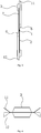
- the radiating fin includes a main body 1 with an oil guide groove 2 formed therein, connecting sleeves 3 extending in a horizontal direction are provided at an upper end and a lower end of the main body 1; a bent radiating portion is formed within a region, a certain distance away from the middle, of an edge of at least one end of the main body 1; and an upper end and a lower end of the bent radiating portion are located in different vertical planes and connected to each other by a twist portion 4, the twist portion 4 including two bending portions 6 in opposite directions.
- the radiating area of the radiating fin is increased and the mechanical strength of the radiating fin is strengthened; and when a plurality of the radiating fins are connected to each other, a combined radial and convective radiating way may be realized, and meanwhile the transverse radiation and the longitudinal radiation of the radiator are strengthened, so that a user may feel the heat more directly.
- Such a structure may further prevent the surface temperature of the radiator from being too high, the heat radiation of the radiator to the surrounding is more uniform, and the radiating efficiency of the radiator is improved, so that the heat radiation around and above the radiator may be balanced during the operation of the electrothermal oil heater.
- the area of the bent radiating portion is 10% to 80% of the total area of the main body, and preferably 40% in this embodiment.
- the bent radiating portion within this range may balance the transverse radiation and the longitudinal radiation of the radiator and ensure the radiating efficiency.
- An included angle between a plane of the upper end and a plane of the lower end is 5° to 85°, and preferably 36° in this embodiment. This angle may ensure the convection at the upper ends or lower ends of two adjacent radiating fins, without damaging the twist portion.
- Terms “upper end” and “lower end” are not provided for defining the upper end and the lower end of the main body 1 and instead, for defining the position relation thereof, hence, a left end and a right end are also possible.
- the upper end and the lower end of the main body 1 are defined as being located in different vertical planes, when the bent radiating portion is located at the left end and right end of the main body 1; and the left end and the right end of the main body 1 are defined as being located in different vertical planes, when the bent radiating portion is located at the upper end and the lower end.
- an annular enclosed portion is provided in the middle of the main body1; the annular enclosed portion divides the main body 1 into a radiating portion 14 located on the outer side of the annular enclosed portion and an oil guide portion 13 located on the inner side of the annular enclosed portion; and the radiating portion 14, on at least one end of the main body 1, is the bent radiating portion.
- Such a structure, in which radiating portion 14, on at least one end of the main body 1, is the bent radiating portion may effectively prevent the deformation of the oil guide portion 13 upon forming the bent radiating portion, avoid the deformation of the oil guide groove 2 or connecting sleeve 3, and prevent a welding point from being burst. It would be helpful to improve the qualified rate and the assembly efficiency of the products.
- the main body 1 includes a big radiating fin and a small radiating fin welded on the big radiating fin; the big radiating portion has the annular enclosed portion arranged in the middle, and the periphery of the small radiating portion is welded to the annular enclosed portion; and a portion, on the outer side of the annular enclosed portion, of the big radiating portion is the radiating portion.
- the radiating fin of the present invention is easy in structure, convenient in assembly and low in cost; and the radiating portion is of a monolayer structure, which is convenient to form the bent radiating portion by punching and stretching.
- the annular enclosed portion is a welding portion on the big radiating portion and the small radiating portion.
- the annular enclosed portion is convenient to machine and firm in connection, and has excellent sealing effect and low production cost.
- curved traces formed by longitudinal cross-sections of any part of the bent radiating portion in the horizontal direction, do not overlap with each other.
- the bent radiating portion with this structure is convenient to be formed, and is prevented from being damaged when it is stretched to the maximum extent.
- the bent radiating portion is formed by punching and stretching.
- the bent radiating portion is convenient to machine and low in production cost.
- the electrothermal oil heater includes a radiator, a heating assembly mounted in the radiator, and an electrically-controlled assembly provided on the radiator, the radiator including a plurality of oil heater radiating fins, the plurality of oil heater radiating fins being connected to each other successively.
- Both the heating assembly and the electrically-controlled assembly are mature technologies in the prior art, and thus will not be repeated here.
- the oil heater radiating fin described in this embodiment is the radiating fin with a bent radiating portion as described in the aforementioned embodiment.
- the radiating fin with a bent radiating portion in the present invention may realize a combined radial and convective radiating way, and meanwhile strengthen the transverse radiation and the longitudinal radiation of the radiator, so that a user may feel the heat more directly. Such a structure may further prevent the surface temperature of the radiator from being too high, the heat radiation of the radiator to the surrounding is more uniform, and the radiating efficiency of the radiator is improved.
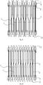
- the radiating fin in the present invention is connected in two ways.
- One is that, a plurality of radiating fins are connected to each other successively, with the back of one of two adjacent radiating fins being opposite to the front of the other; and the other way is that, a plurality of radiating fins are connected to each other successively, with the back of one of two adjacent radiating fins being opposite to the back of the other, or the front of one of two adjacent radiating fins being opposite to the front of the other.
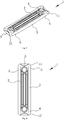
- this embodiment is roughly the same as the aforementioned embodiment 1, with the difference in that the upper end and the lower end of the bent radiating portion in this embodiment are located in a same vertical plane and connected to each other by a bent portion 5, the bent portion 5 including two bending portions 6 in a same direction.
- An included angle between a vertical projection of the upper end and the lower end and a vertical projection of the bent portion is 5° to 85°, and preferably 36° in this embodiment. This angle may ensure the convection of upper ends and the lower ends of two adjacent radiating fins, without damaging the twisted portion.
- a distance from an apex of the bent portion 5 to the plane of the upper end and the lower end is 5 mm to 70 mm, and preferably 20 mm in this embodiment.
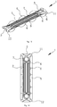
- this embodiment is roughly the same as the aforementioned embodiment 1, with the difference in that the upper end and the lower end of the bent radiating portion in this embodiment are located in a same vertical plane and connected to each other by a plurality of bent portions 5, two adjacent bent portions 5 are bent in opposite directions, and each of the bent portions 5 includes two bending portions 6 in a same direction.
- An included angle between a vertical projection of the upper end and the lower end and a vertical projection of the bent portion is 5° to 85°, and preferably 36° in this embodiment. This angle may ensure the convection of upper ends and the lower ends of two adjacent radiating fins, without damaging the twisted portion.
- a distance from an apex of the bent portion to the plane of the upper end and the lower end is 5 mm to 70 mm, and preferably 20 mm in this embodiment.
Landscapes
- Engineering & Computer Science (AREA)
- Mechanical Engineering (AREA)
- General Engineering & Computer Science (AREA)
- Physics & Mathematics (AREA)
- Thermal Sciences (AREA)
- Chemical & Material Sciences (AREA)
- Combustion & Propulsion (AREA)
- Central Heating Systems (AREA)
- Cooling Or The Like Of Electrical Apparatus (AREA)
- Domestic Hot-Water Supply Systems And Details Of Heating Systems (AREA)
Claims (14)
- Strahlungsrippe mit einem gekrümmten Abstrahlungsabschnitt, umfassend einen Hauptkörper (1) mit einer darin ausgebildeten Ölführungsnut (2), wobei Anschlussmuffen (3), die sich in horizontaler Richtung erstrecken, an einem oberen Ende und einem unteren Ende des Hauptkörpers (1) vorgesehen sind, wobei
ein gekrümmter Abstrahlungsabschnitt in einem in einem bestimmten Abstand von der Mitte befindlichen Bereich eines Rands von wenigstens einem Ende des Hauptkörpers (1) ausgebildet ist, wobei die Fläche des gekrümmten Abstrahlungsabschnitts 10 Prozent bis 80 Prozent der Gesamtfläche des Hauptkörpers (1) beträgt, dadurch gekennzeichnet, dass sich ein oberes Ende (11) und ein unteres Ende (12) des gekrümmten Abstrahlungsabschnitts in unterschiedlichen vertikalen Ebenen befinden und über einen gewundenen Abschnitt (4) miteinander verbunden sind oder dass sich das obere Ende (11) und das untere Ende (12) des gekrümmten Abstrahlungsabschnitts in einer gleichen vertikalen Ebene befinden und über eine Vielzahl von gekrümmten Abschnitten (5) miteinander verbunden sind, wobei die gekrümmten Abschnitte (5) jeweils zwei Krümmungsabschnitte (6) in einer gleichen Richtung umfassen. - Strahlungsrippe mit einem gekrümmten Abstrahlungsabschnitt nach Anspruch 1, dadurch gekennzeichnet, dass der gewundene Abschnitt (4) zwei Krümmungsabschnitte (6) in entgegengesetzten Richtungen umfasst.
- Strahlungsrippe mit einem gekrümmten Abstrahlungsabschnitt nach Anspruch 2, dadurch gekennzeichnet, dass ein zwischen einer Ebene des oberen Endes (11) des gekrümmten Abstrahlungsabschnitts und einer Ebene des unteren Endes (12) des gekrümmten Abstrahlungsabschnitts eingeschlossener Winkel zwischen 5 Grad und 85 Grad liegt.
- Strahlungsrippe mit einem gekrümmten Abstrahlungsabschnitt nach Anspruch 1, dadurch gekennzeichnet, dass sich das obere Ende (11) und das untere Ende (12) des gekrümmten Abstrahlungsabschnitts in einer gleichen vertikalen Ebene befinden und über einen gekrümmten Abschnitt (5) miteinander verbunden sind, wobei der gekrümmte Abschnitt (5) zwei Krümmungsabschnitte (6) in einer gleichen Richtung umfasst.
- Strahlungsrippe mit einem gekrümmten Abstrahlungsabschnitt nach Anspruch 4, dadurch gekennzeichnet, dass ein zwischen einem vertikalen Vorsprung des oberen Endes (11) und des unteren Endes (12) des gekrümmten Abstrahlungsabschnitts und einem vertikalen Vorsprung des gekrümmten Abschnitts (5) eingeschlossener Winkel zwischen 5 Grad und 85 Grad liegt.
- Strahlungsrippe mit einem gekrümmten Abstrahlungsabschnitt nach Anspruch 4, dadurch gekennzeichnet, dass ein Abstand eines Scheitelpunkts des gekrümmten Abschnitts (5) von der Ebene des oberen Endes (11) und des unteren Endes (12) des gekrümmten Abstrahlungsabschnitts zwischen 5 mm und 70 mm liegt.
- Strahlungsrippe mit einem gekrümmten Abstrahlungsabschnitt nach Anspruch 1, dadurch gekennzeichnet, dass zwei benachbarte gekrümmte Abschnitte (5) in entgegengesetzten Richtungen gekrümmt sind.
- Strahlungsrippe mit einem gekrümmten Abstrahlungsabschnitt nach Anspruch 1, dadurch gekennzeichnet, dass ein zwischen einem vertikalen Vorsprung des oberen Endes (11) und des unteren Endes (12) des gekrümmten Abstrahlungsabschnitts und einem vertikalen Vorsprung des gekrümmten Abschnitts (5) eingeschlossener Winkel zwischen 5 Grad und 85 Grad liegt.
- Strahlungsrippe mit einem gekrümmten Abstrahlungsabschnitt nach Anspruch 1, dadurch gekennzeichnet, dass ein Abstand eines Scheitelpunkts des gekrümmten Abschnitts (5) von der Ebene des oberen Endes (11) und des unteren Endes (12) des gekrümmten Abstrahlungsabschnitts zwischen 5 mm und 70 mm liegt.
- Strahlungsrippe mit einem gekrümmten Abstrahlungsabschnitt nach einem der Ansprüche 1 bis 9, dadurch gekennzeichnet, dass in der Mitte des Hauptkörpers (1) ein ringförmiger umschlossener Abschnitt vorgesehen ist, wobei der ringförmige umschlossene Abschnitt den Hauptkörper (1) in einen Abstrahlungsabschnitt (14), der sich auf der Außenseite des ringförmigen umschlossenen Abschnitts befindet, und einen Ölführungsabschnitt (13), der sich auf der Innenseite des ringförmigen umschlossenen Abschnitts befindet, unterteilt und es sich bei dem Abstrahlungsabschnitt (14) an wenigstens einem Ende des Hauptkörpers (1) um den gekrümmten Abstrahlungsabschnitt handelt.
- Strahlungsrippe mit einem gekrümmten Abstrahlungsabschnitt nach Anspruch 10, dadurch gekennzeichnet, dass der Hauptkörper (1) eine große Strahlungsrippe und eine auf die große Strahlungsrippe aufgeschweißte kleine Strahlungsrippe umfasst, wobei der große Abstrahlungsabschnitt den in der Mitte angeordneten ringförmigen umschlossenen Abschnitt aufweist und der Umfang des kleinen Abstrahlungsabschnitts mit dem ringförmigen umschlossenen Abschnitt verschweißt ist und es sich bei einem auf der Außenseite des ringförmigen umschlossenen Abschnitts gelegenen Abschnitt des großen Abstrahlungsabschnitts um den Abstrahlungsabschnitt (14) handelt.
- Strahlungsrippe mit einem gekrümmten Abstrahlungsabschnitt nach einem der Ansprüche 1 bis 9, dadurch gekennzeichnet, dass sich bogenförmige Spuren, die durch Längsquerschnitte beliebiger Teile des gekrümmten Abstrahlungsabschnitts in horizontaler Richtung gebildet sind, nicht überlappen.
- Strahlungsrippe mit einem gekrümmten Abstrahlungsabschnitt nach einem der Ansprüche 1 bis 9, dadurch gekennzeichnet, dass der gekrümmte Abstrahlungsabschnitt durch Stanzen und Strecken ausgebildet ist.
- Elektrothermische Ölheizung, umfassend einen Heizkörper, eine in dem Heizkörper montierte Heizungsanordnung und eine an dem Heizkörper vorgesehene elektrisch gesteuerte Anordnung, wobei der Heizkörper eine Vielzahl von Strahlungsrippen mit einem gekrümmten Abstrahlungsabschnitt umfasst, wobei die Vielzahl von Strahlungsrippen der Reihe nach miteinander verbunden sind, dadurch gekennzeichnet, dass es sich bei den Strahlungsrippen mit einem gekrümmten Abstrahlungsabschnitt um die Strahlungsrippen mit einem gekrümmten Abstrahlungsabschnitt nach einem der Ansprüche 1 bis 13 handelt.
Applications Claiming Priority (1)
| Application Number | Priority Date | Filing Date | Title |
|---|---|---|---|
| CN201410855616.7A CN104654433B (zh) | 2014-12-31 | 2014-12-31 | 带有曲折散热部的散热片及使用该散热片的电热油汀 |
Publications (2)
| Publication Number | Publication Date |
|---|---|
| EP3040639A1 EP3040639A1 (de) | 2016-07-06 |
| EP3040639B1 true EP3040639B1 (de) | 2017-09-27 |
Family
ID=53245861
Family Applications (1)
| Application Number | Title | Priority Date | Filing Date |
|---|---|---|---|
| EP15198325.1A Not-in-force EP3040639B1 (de) | 2014-12-31 | 2015-12-08 | Strahlungsrippe mit gekrümmten abstrahlungsabschnitt und elektrothermische ölheizung damit |
Country Status (6)
| Country | Link |
|---|---|
| US (1) | US10190831B2 (de) |
| EP (1) | EP3040639B1 (de) |
| JP (1) | JP6139644B2 (de) |
| KR (1) | KR101964781B1 (de) |
| CN (1) | CN104654433B (de) |
| RU (1) | RU2623135C2 (de) |
Families Citing this family (6)
| Publication number | Priority date | Publication date | Assignee | Title |
|---|---|---|---|---|
| CN105890030A (zh) * | 2016-06-24 | 2016-08-24 | 珠海格力电器股份有限公司 | 散热装置及具有其的取暖装置 |
| CN109520326B (zh) * | 2017-09-18 | 2024-05-28 | 美的集团股份有限公司 | 取暖器 |
| CN109268917B (zh) * | 2018-11-27 | 2024-08-06 | 宁波先锋电器制造有限公司 | 一种散热组件及电热油汀 |
| CN109751657A (zh) * | 2019-02-25 | 2019-05-14 | 珠海格力电器股份有限公司 | 散热结构及具有其的油汀 |
| CN111520806B (zh) * | 2020-05-13 | 2021-11-02 | 商艳萍 | 一种油汀散热片的制作方法 |
| CN112879992A (zh) * | 2021-03-25 | 2021-06-01 | 宁波先锋电器制造有限公司 | 一种防烫油汀 |
Family Cites Families (35)
| Publication number | Priority date | Publication date | Assignee | Title |
|---|---|---|---|---|
| GB190907403A (en) * | 1909-03-27 | 1910-03-10 | Thomas Henry Harris | Improvements in connection with Cooling Devices, Radiators and the like. |
| SU79711A1 (ru) * | 1948-02-02 | 1948-11-30 | Л.А. Погоржельский | Радиатор-конвектор |
| US4002201A (en) * | 1974-05-24 | 1977-01-11 | Borg-Warner Corporation | Multiple fluid stacked plate heat exchanger |
| US4011905A (en) * | 1975-12-18 | 1977-03-15 | Borg-Warner Corporation | Heat exchangers with integral surge tanks |
| US4336444A (en) * | 1980-01-14 | 1982-06-22 | Gust, Irish, Jeffers & Hoffman | Apparatus and method for converting electrical energy into heat energy |
| US4369838A (en) * | 1980-05-27 | 1983-01-25 | Aluminum Kabushiki Kaisha Showa | Device for releasing heat |
| JPS5732837A (en) * | 1980-08-08 | 1982-02-22 | Hitachi Ltd | Method for manufacturing cross fin type heat exchanger |
| JPS57120036A (en) * | 1981-11-30 | 1982-07-26 | Matsushita Electric Ind Co Ltd | Radiation type space heater |
| DE3435934A1 (de) * | 1984-09-29 | 1986-04-03 | Hans Dipl.-Ing. Schupper (FH), 7863 Zell | Konvektions-reflektor zur reduzierung der waermeverluste an heizkoerpernischen |
| ES8802195A1 (es) * | 1986-06-23 | 1988-04-01 | Cb 4831 Sa | Radiador domestico perfeccionado |
| JPH01112635A (ja) * | 1987-10-23 | 1989-05-01 | Matsushita Electron Corp | マグネトロン装置 |
| JPH0533959A (ja) * | 1991-08-01 | 1993-02-09 | Matsushita Seiko Co Ltd | オイル循環式パネルヒータ |
| WO1993017290A1 (en) * | 1992-02-28 | 1993-09-02 | Melanesia International Trust Company Limited | Heat exchanger assembly |
| US5390731A (en) * | 1994-06-29 | 1995-02-21 | Ford Motor Company | Heat exchanger fin |
| KR960011914U (ko) * | 1994-09-16 | 1996-04-15 | 열교환기 | |
| GB9703040D0 (en) * | 1996-07-12 | 1997-04-02 | Basic Patents | Space heaters |
| US20020046826A1 (en) * | 2000-10-25 | 2002-04-25 | Chao-Chih Kao | CPU cooling structure |
| US6672376B2 (en) * | 2000-12-27 | 2004-01-06 | Visteon Global Technologies, Inc. | Twisted-louver high performance heat exchanger fin |
| TWM263734U (en) * | 2004-05-14 | 2005-05-01 | Hung-Yi Lin | Cooling fin with wind deflecting leading edge |
| EP1826494B1 (de) * | 2004-12-13 | 2015-12-09 | Guoning Yao | Art von verbessertem mit öl gefülltem elektrischem heizer |
| CN2783184Y (zh) * | 2004-12-20 | 2006-05-24 | 姚国宁 | 改进的散热片及安装有该散热片的充油式电暖器 |
| JP2007054968A (ja) * | 2005-08-22 | 2007-03-08 | Funai Electric Co Ltd | 画像形成装置 |
| CN200958800Y (zh) * | 2006-06-19 | 2007-10-10 | 何耀林 | 电暖器之热交换增益构造 |
| JP4281789B2 (ja) * | 2006-12-06 | 2009-06-17 | トヨタ自動車株式会社 | 排気熱回収装置 |
| US8180205B2 (en) * | 2007-01-12 | 2012-05-15 | Guoning Yao | Electrothermal oil radiator |
| CN201047642Y (zh) * | 2007-06-06 | 2008-04-16 | 黄纪东 | 一种电热油汀 |
| CN201387077Y (zh) * | 2009-01-19 | 2010-01-20 | 美的集团有限公司 | 一种取暖器的散热片 |
| CN102401358B (zh) * | 2010-09-10 | 2016-08-03 | 欧司朗股份有限公司 | 冷却体的制造方法、冷却体以及具有该冷却体的照明装置 |
| JP5338012B2 (ja) * | 2010-09-30 | 2013-11-13 | ツォンシャン ウェイキアン テクノロジー カンパニー、リミテッド | ハイパワー放熱モジュール |
| JP5413433B2 (ja) * | 2010-11-09 | 2014-02-12 | 株式会社デンソー | 熱交換器 |
| RU123123U1 (ru) * | 2012-03-20 | 2012-12-20 | Общество с ограниченной ответственностью "Ай.Эр.Эм.Си" | Секционный радиатор |
| CN102644966A (zh) * | 2012-04-16 | 2012-08-22 | 宁波先锋电器制造有限公司 | 一种油汀散热片及使用该散热片的电热油汀 |
| CN103822291B (zh) * | 2014-03-07 | 2017-01-11 | 宁波先锋电器制造有限公司 | 带有散热通道的电热油汀 |
| CN203785071U (zh) * | 2014-05-02 | 2014-08-20 | 佛山市顺德区富迪威电器有限公司 | 高效电热油汀 |
| AU359830S (en) * | 2014-07-03 | 2015-01-13 | Delonghi Appliances Srl Con Unico Socio | Radiator |
-
2014
- 2014-12-31 CN CN201410855616.7A patent/CN104654433B/zh active Active
-
2015
- 2015-12-02 JP JP2015235533A patent/JP6139644B2/ja not_active Expired - Fee Related
- 2015-12-08 EP EP15198325.1A patent/EP3040639B1/de not_active Not-in-force
- 2015-12-15 US US14/970,249 patent/US10190831B2/en active Active
- 2015-12-18 RU RU2015154529A patent/RU2623135C2/ru active IP Right Revival
- 2015-12-21 KR KR1020150182628A patent/KR101964781B1/ko not_active Expired - Fee Related
Non-Patent Citations (1)
| Title |
|---|
| None * |
Also Published As
| Publication number | Publication date |
|---|---|
| KR20160081802A (ko) | 2016-07-08 |
| CN104654433A (zh) | 2015-05-27 |
| RU2015154529A (ru) | 2017-06-21 |
| US20160187073A1 (en) | 2016-06-30 |
| JP2016125806A (ja) | 2016-07-11 |
| EP3040639A1 (de) | 2016-07-06 |
| CN104654433B (zh) | 2018-05-01 |
| JP6139644B2 (ja) | 2017-05-31 |
| RU2623135C2 (ru) | 2017-06-22 |
| US10190831B2 (en) | 2019-01-29 |
| KR101964781B1 (ko) | 2019-04-02 |
Similar Documents
| Publication | Publication Date | Title |
|---|---|---|
| EP3040639B1 (de) | Strahlungsrippe mit gekrümmten abstrahlungsabschnitt und elektrothermische ölheizung damit | |
| CN204373053U (zh) | 带有弯折散热部的散热片及使用该散热片的电热油汀 | |
| CN103822291B (zh) | 带有散热通道的电热油汀 | |
| KR101766723B1 (ko) | 콤팩트형 방열기 | |
| CN108151565B (zh) | 立体均温装置 | |
| CN201403216Y (zh) | 大翅片式电加热器 | |
| CN202328473U (zh) | 一种新型电取暖器发热体 | |
| CN204373045U (zh) | 散热通道间隔设置的电热油汀 | |
| CN205261721U (zh) | 一种带有封闭式管型散热通道的电热油汀 | |
| CN204373051U (zh) | 带有曲折散热部的散热片及使用该散热片的电热油汀 | |
| CN204084572U (zh) | 一种具有敞开式散热通道的电热油汀 | |
| CN202652570U (zh) | 高效易成型发热管 | |
| CN202501554U (zh) | 一种电暖器的空气加热部件 | |
| CN201993023U (zh) | 电热油汀及其散热片结构 | |
| CN205300348U (zh) | W型鳍片管 | |
| CN105180678A (zh) | 一种换热器 | |
| CN204649054U (zh) | 一种分体式散热器 | |
| CN203645838U (zh) | 一种发热装置的铝翅片结构 | |
| CN202734637U (zh) | 一种鳍片换热管 | |
| CN203704123U (zh) | 一种带有网格散热片的电热油汀 | |
| CN202814188U (zh) | 一种梅花管换热管 | |
| CN208475442U (zh) | 一种散热片及取暖器 | |
| CN102721315A (zh) | 电热油汀及其散热片结构 | |
| CN204084573U (zh) | 一种具有管状散热通道的电热油汀 | |
| CN105806126A (zh) | 管式换热结构 |
Legal Events
| Date | Code | Title | Description |
|---|---|---|---|
| PUAI | Public reference made under article 153(3) epc to a published international application that has entered the european phase |
Free format text: ORIGINAL CODE: 0009012 |
|
| AK | Designated contracting states |
Kind code of ref document: A1 Designated state(s): AL AT BE BG CH CY CZ DE DK EE ES FI FR GB GR HR HU IE IS IT LI LT LU LV MC MK MT NL NO PL PT RO RS SE SI SK SM TR |
|
| AX | Request for extension of the european patent |
Extension state: BA ME |
|
| 17P | Request for examination filed |
Effective date: 20161025 |
|
| RBV | Designated contracting states (corrected) |
Designated state(s): AL AT BE BG CH CY CZ DE DK EE ES FI FR GB GR HR HU IE IS IT LI LT LU LV MC MK MT NL NO PL PT RO RS SE SI SK SM TR |
|
| GRAP | Despatch of communication of intention to grant a patent |
Free format text: ORIGINAL CODE: EPIDOSNIGR1 |
|
| RIC1 | Information provided on ipc code assigned before grant |
Ipc: F28D 1/03 20060101ALI20170329BHEP Ipc: F28F 1/18 20060101ALI20170329BHEP Ipc: F24H 3/00 20060101AFI20170329BHEP Ipc: F28D 1/02 20060101ALI20170329BHEP Ipc: F28D 1/053 20060101ALI20170329BHEP Ipc: F28F 3/02 20060101ALI20170329BHEP |
|
| INTG | Intention to grant announced |
Effective date: 20170421 |
|
| GRAS | Grant fee paid |
Free format text: ORIGINAL CODE: EPIDOSNIGR3 |
|
| GRAA | (expected) grant |
Free format text: ORIGINAL CODE: 0009210 |
|
| AK | Designated contracting states |
Kind code of ref document: B1 Designated state(s): AL AT BE BG CH CY CZ DE DK EE ES FI FR GB GR HR HU IE IS IT LI LT LU LV MC MK MT NL NO PL PT RO RS SE SI SK SM TR |
|
| REG | Reference to a national code |
Ref country code: GB Ref legal event code: FG4D |
|
| REG | Reference to a national code |
Ref country code: CH Ref legal event code: EP |
|
| REG | Reference to a national code |
Ref country code: AT Ref legal event code: REF Ref document number: 932325 Country of ref document: AT Kind code of ref document: T Effective date: 20171015 |
|
| REG | Reference to a national code |
Ref country code: IE Ref legal event code: FG4D |
|
| REG | Reference to a national code |
Ref country code: DE Ref legal event code: R096 Ref document number: 602015004998 Country of ref document: DE |
|
| PG25 | Lapsed in a contracting state [announced via postgrant information from national office to epo] |
Ref country code: NO Free format text: LAPSE BECAUSE OF FAILURE TO SUBMIT A TRANSLATION OF THE DESCRIPTION OR TO PAY THE FEE WITHIN THE PRESCRIBED TIME-LIMIT Effective date: 20171227 Ref country code: LT Free format text: LAPSE BECAUSE OF FAILURE TO SUBMIT A TRANSLATION OF THE DESCRIPTION OR TO PAY THE FEE WITHIN THE PRESCRIBED TIME-LIMIT Effective date: 20170927 Ref country code: FI Free format text: LAPSE BECAUSE OF FAILURE TO SUBMIT A TRANSLATION OF THE DESCRIPTION OR TO PAY THE FEE WITHIN THE PRESCRIBED TIME-LIMIT Effective date: 20170927 Ref country code: HR Free format text: LAPSE BECAUSE OF FAILURE TO SUBMIT A TRANSLATION OF THE DESCRIPTION OR TO PAY THE FEE WITHIN THE PRESCRIBED TIME-LIMIT Effective date: 20170927 Ref country code: SE Free format text: LAPSE BECAUSE OF FAILURE TO SUBMIT A TRANSLATION OF THE DESCRIPTION OR TO PAY THE FEE WITHIN THE PRESCRIBED TIME-LIMIT Effective date: 20170927 |
|
| REG | Reference to a national code |
Ref country code: NL Ref legal event code: MP Effective date: 20170927 |
|
| REG | Reference to a national code |
Ref country code: LT Ref legal event code: MG4D |
|
| REG | Reference to a national code |
Ref country code: AT Ref legal event code: MK05 Ref document number: 932325 Country of ref document: AT Kind code of ref document: T Effective date: 20170927 |
|
| PG25 | Lapsed in a contracting state [announced via postgrant information from national office to epo] |
Ref country code: RS Free format text: LAPSE BECAUSE OF FAILURE TO SUBMIT A TRANSLATION OF THE DESCRIPTION OR TO PAY THE FEE WITHIN THE PRESCRIBED TIME-LIMIT Effective date: 20170927 Ref country code: BG Free format text: LAPSE BECAUSE OF FAILURE TO SUBMIT A TRANSLATION OF THE DESCRIPTION OR TO PAY THE FEE WITHIN THE PRESCRIBED TIME-LIMIT Effective date: 20171227 Ref country code: LV Free format text: LAPSE BECAUSE OF FAILURE TO SUBMIT A TRANSLATION OF THE DESCRIPTION OR TO PAY THE FEE WITHIN THE PRESCRIBED TIME-LIMIT Effective date: 20170927 Ref country code: GR Free format text: LAPSE BECAUSE OF FAILURE TO SUBMIT A TRANSLATION OF THE DESCRIPTION OR TO PAY THE FEE WITHIN THE PRESCRIBED TIME-LIMIT Effective date: 20171228 |
|
| PG25 | Lapsed in a contracting state [announced via postgrant information from national office to epo] |
Ref country code: NL Free format text: LAPSE BECAUSE OF FAILURE TO SUBMIT A TRANSLATION OF THE DESCRIPTION OR TO PAY THE FEE WITHIN THE PRESCRIBED TIME-LIMIT Effective date: 20170927 |
|
| PG25 | Lapsed in a contracting state [announced via postgrant information from national office to epo] |
Ref country code: ES Free format text: LAPSE BECAUSE OF FAILURE TO SUBMIT A TRANSLATION OF THE DESCRIPTION OR TO PAY THE FEE WITHIN THE PRESCRIBED TIME-LIMIT Effective date: 20170927 Ref country code: RO Free format text: LAPSE BECAUSE OF FAILURE TO SUBMIT A TRANSLATION OF THE DESCRIPTION OR TO PAY THE FEE WITHIN THE PRESCRIBED TIME-LIMIT Effective date: 20170927 Ref country code: CZ Free format text: LAPSE BECAUSE OF FAILURE TO SUBMIT A TRANSLATION OF THE DESCRIPTION OR TO PAY THE FEE WITHIN THE PRESCRIBED TIME-LIMIT Effective date: 20170927 |
|
| PG25 | Lapsed in a contracting state [announced via postgrant information from national office to epo] |
Ref country code: IT Free format text: LAPSE BECAUSE OF FAILURE TO SUBMIT A TRANSLATION OF THE DESCRIPTION OR TO PAY THE FEE WITHIN THE PRESCRIBED TIME-LIMIT Effective date: 20170927 Ref country code: AT Free format text: LAPSE BECAUSE OF FAILURE TO SUBMIT A TRANSLATION OF THE DESCRIPTION OR TO PAY THE FEE WITHIN THE PRESCRIBED TIME-LIMIT Effective date: 20170927 Ref country code: IS Free format text: LAPSE BECAUSE OF FAILURE TO SUBMIT A TRANSLATION OF THE DESCRIPTION OR TO PAY THE FEE WITHIN THE PRESCRIBED TIME-LIMIT Effective date: 20180127 Ref country code: SM Free format text: LAPSE BECAUSE OF FAILURE TO SUBMIT A TRANSLATION OF THE DESCRIPTION OR TO PAY THE FEE WITHIN THE PRESCRIBED TIME-LIMIT Effective date: 20170927 Ref country code: SK Free format text: LAPSE BECAUSE OF FAILURE TO SUBMIT A TRANSLATION OF THE DESCRIPTION OR TO PAY THE FEE WITHIN THE PRESCRIBED TIME-LIMIT Effective date: 20170927 Ref country code: EE Free format text: LAPSE BECAUSE OF FAILURE TO SUBMIT A TRANSLATION OF THE DESCRIPTION OR TO PAY THE FEE WITHIN THE PRESCRIBED TIME-LIMIT Effective date: 20170927 |
|
| REG | Reference to a national code |
Ref country code: DE Ref legal event code: R097 Ref document number: 602015004998 Country of ref document: DE |
|
| REG | Reference to a national code |
Ref country code: DE Ref legal event code: R119 Ref document number: 602015004998 Country of ref document: DE |
|
| PG25 | Lapsed in a contracting state [announced via postgrant information from national office to epo] |
Ref country code: DK Free format text: LAPSE BECAUSE OF FAILURE TO SUBMIT A TRANSLATION OF THE DESCRIPTION OR TO PAY THE FEE WITHIN THE PRESCRIBED TIME-LIMIT Effective date: 20170927 |
|
| PLBE | No opposition filed within time limit |
Free format text: ORIGINAL CODE: 0009261 |
|
| STAA | Information on the status of an ep patent application or granted ep patent |
Free format text: STATUS: NO OPPOSITION FILED WITHIN TIME LIMIT |
|
| PG25 | Lapsed in a contracting state [announced via postgrant information from national office to epo] |
Ref country code: PL Free format text: LAPSE BECAUSE OF FAILURE TO SUBMIT A TRANSLATION OF THE DESCRIPTION OR TO PAY THE FEE WITHIN THE PRESCRIBED TIME-LIMIT Effective date: 20170927 |
|
| 26N | No opposition filed |
Effective date: 20180628 |
|
| REG | Reference to a national code |
Ref country code: IE Ref legal event code: MM4A |
|
| PG25 | Lapsed in a contracting state [announced via postgrant information from national office to epo] |
Ref country code: LU Free format text: LAPSE BECAUSE OF NON-PAYMENT OF DUE FEES Effective date: 20171208 Ref country code: MT Free format text: LAPSE BECAUSE OF NON-PAYMENT OF DUE FEES Effective date: 20171208 |
|
| REG | Reference to a national code |
Ref country code: FR Ref legal event code: ST Effective date: 20180831 |
|
| REG | Reference to a national code |
Ref country code: BE Ref legal event code: MM Effective date: 20171231 |
|
| PG25 | Lapsed in a contracting state [announced via postgrant information from national office to epo] |
Ref country code: IE Free format text: LAPSE BECAUSE OF NON-PAYMENT OF DUE FEES Effective date: 20171208 Ref country code: FR Free format text: LAPSE BECAUSE OF NON-PAYMENT OF DUE FEES Effective date: 20180102 Ref country code: DE Free format text: LAPSE BECAUSE OF NON-PAYMENT OF DUE FEES Effective date: 20180703 |
|
| PG25 | Lapsed in a contracting state [announced via postgrant information from national office to epo] |
Ref country code: SI Free format text: LAPSE BECAUSE OF FAILURE TO SUBMIT A TRANSLATION OF THE DESCRIPTION OR TO PAY THE FEE WITHIN THE PRESCRIBED TIME-LIMIT Effective date: 20170927 Ref country code: BE Free format text: LAPSE BECAUSE OF NON-PAYMENT OF DUE FEES Effective date: 20171231 |
|
| PG25 | Lapsed in a contracting state [announced via postgrant information from national office to epo] |
Ref country code: MC Free format text: LAPSE BECAUSE OF FAILURE TO SUBMIT A TRANSLATION OF THE DESCRIPTION OR TO PAY THE FEE WITHIN THE PRESCRIBED TIME-LIMIT Effective date: 20170927 Ref country code: HU Free format text: LAPSE BECAUSE OF FAILURE TO SUBMIT A TRANSLATION OF THE DESCRIPTION OR TO PAY THE FEE WITHIN THE PRESCRIBED TIME-LIMIT; INVALID AB INITIO Effective date: 20151208 |
|
| REG | Reference to a national code |
Ref country code: CH Ref legal event code: PL |
|
| PG25 | Lapsed in a contracting state [announced via postgrant information from national office to epo] |
Ref country code: CY Free format text: LAPSE BECAUSE OF FAILURE TO SUBMIT A TRANSLATION OF THE DESCRIPTION OR TO PAY THE FEE WITHIN THE PRESCRIBED TIME-LIMIT Effective date: 20170927 |
|
| PG25 | Lapsed in a contracting state [announced via postgrant information from national office to epo] |
Ref country code: MK Free format text: LAPSE BECAUSE OF FAILURE TO SUBMIT A TRANSLATION OF THE DESCRIPTION OR TO PAY THE FEE WITHIN THE PRESCRIBED TIME-LIMIT Effective date: 20170927 |
|
| PG25 | Lapsed in a contracting state [announced via postgrant information from national office to epo] |
Ref country code: CH Free format text: LAPSE BECAUSE OF NON-PAYMENT OF DUE FEES Effective date: 20181231 Ref country code: LI Free format text: LAPSE BECAUSE OF NON-PAYMENT OF DUE FEES Effective date: 20181231 |
|
| PG25 | Lapsed in a contracting state [announced via postgrant information from national office to epo] |
Ref country code: TR Free format text: LAPSE BECAUSE OF FAILURE TO SUBMIT A TRANSLATION OF THE DESCRIPTION OR TO PAY THE FEE WITHIN THE PRESCRIBED TIME-LIMIT Effective date: 20170927 |
|
| PG25 | Lapsed in a contracting state [announced via postgrant information from national office to epo] |
Ref country code: PT Free format text: LAPSE BECAUSE OF FAILURE TO SUBMIT A TRANSLATION OF THE DESCRIPTION OR TO PAY THE FEE WITHIN THE PRESCRIBED TIME-LIMIT Effective date: 20170927 |
|
| PG25 | Lapsed in a contracting state [announced via postgrant information from national office to epo] |
Ref country code: AL Free format text: LAPSE BECAUSE OF FAILURE TO SUBMIT A TRANSLATION OF THE DESCRIPTION OR TO PAY THE FEE WITHIN THE PRESCRIBED TIME-LIMIT Effective date: 20170927 |
|
| GBPC | Gb: european patent ceased through non-payment of renewal fee |
Effective date: 20191208 |
|
| PG25 | Lapsed in a contracting state [announced via postgrant information from national office to epo] |
Ref country code: GB Free format text: LAPSE BECAUSE OF NON-PAYMENT OF DUE FEES Effective date: 20191208 |