EP3042754B1 - Device for automatically layering prepreg sheets and method for layering prepreg sheets - Google Patents
Device for automatically layering prepreg sheets and method for layering prepreg sheets Download PDFInfo
- Publication number
- EP3042754B1 EP3042754B1 EP14860804.5A EP14860804A EP3042754B1 EP 3042754 B1 EP3042754 B1 EP 3042754B1 EP 14860804 A EP14860804 A EP 14860804A EP 3042754 B1 EP3042754 B1 EP 3042754B1
- Authority
- EP
- European Patent Office
- Prior art keywords
- sheet
- semi
- layered
- prepreg
- roller
- Prior art date
- Legal status (The legal status is an assumption and is not a legal conclusion. Google has not performed a legal analysis and makes no representation as to the accuracy of the status listed.)
- Active
Links
Images

Classifications
-
- B—PERFORMING OPERATIONS; TRANSPORTING
- B29—WORKING OF PLASTICS; WORKING OF SUBSTANCES IN A PLASTIC STATE IN GENERAL
- B29C—SHAPING OR JOINING OF PLASTICS; SHAPING OF MATERIAL IN A PLASTIC STATE, NOT OTHERWISE PROVIDED FOR; AFTER-TREATMENT OF THE SHAPED PRODUCTS, e.g. REPAIRING
- B29C70/00—Shaping composites, i.e. plastics material comprising reinforcements, fillers or preformed parts, e.g. inserts
- B29C70/04—Shaping composites, i.e. plastics material comprising reinforcements, fillers or preformed parts, e.g. inserts comprising reinforcements only, e.g. self-reinforcing plastics
- B29C70/28—Shaping operations therefor
- B29C70/30—Shaping by lay-up, i.e. applying fibres, tape or broadsheet on a mould, former or core; Shaping by spray-up, i.e. spraying of fibres on a mould, former or core
- B29C70/38—Automated lay-up, e.g. using robots, laying filaments according to predetermined patterns
- B29C70/386—Automated tape laying [ATL]
- B29C70/388—Tape placement heads, e.g. component parts, details or accessories
-
- B—PERFORMING OPERATIONS; TRANSPORTING
- B29—WORKING OF PLASTICS; WORKING OF SUBSTANCES IN A PLASTIC STATE IN GENERAL
- B29C—SHAPING OR JOINING OF PLASTICS; SHAPING OF MATERIAL IN A PLASTIC STATE, NOT OTHERWISE PROVIDED FOR; AFTER-TREATMENT OF THE SHAPED PRODUCTS, e.g. REPAIRING
- B29C33/00—Moulds or cores; Details thereof or accessories therefor
- B29C33/56—Coatings, e.g. enameled or galvanised; Releasing, lubricating or separating agents
- B29C33/68—Release sheets
-
- B—PERFORMING OPERATIONS; TRANSPORTING
- B29—WORKING OF PLASTICS; WORKING OF SUBSTANCES IN A PLASTIC STATE IN GENERAL
- B29C—SHAPING OR JOINING OF PLASTICS; SHAPING OF MATERIAL IN A PLASTIC STATE, NOT OTHERWISE PROVIDED FOR; AFTER-TREATMENT OF THE SHAPED PRODUCTS, e.g. REPAIRING
- B29C35/00—Heating, cooling or curing, e.g. crosslinking or vulcanising; Apparatus therefor
- B29C35/02—Heating or curing, e.g. crosslinking or vulcanizing during moulding, e.g. in a mould
-
- B—PERFORMING OPERATIONS; TRANSPORTING
- B29—WORKING OF PLASTICS; WORKING OF SUBSTANCES IN A PLASTIC STATE IN GENERAL
- B29C—SHAPING OR JOINING OF PLASTICS; SHAPING OF MATERIAL IN A PLASTIC STATE, NOT OTHERWISE PROVIDED FOR; AFTER-TREATMENT OF THE SHAPED PRODUCTS, e.g. REPAIRING
- B29C35/00—Heating, cooling or curing, e.g. crosslinking or vulcanising; Apparatus therefor
- B29C35/16—Cooling
-
- B—PERFORMING OPERATIONS; TRANSPORTING
- B29—WORKING OF PLASTICS; WORKING OF SUBSTANCES IN A PLASTIC STATE IN GENERAL
- B29C—SHAPING OR JOINING OF PLASTICS; SHAPING OF MATERIAL IN A PLASTIC STATE, NOT OTHERWISE PROVIDED FOR; AFTER-TREATMENT OF THE SHAPED PRODUCTS, e.g. REPAIRING
- B29C70/00—Shaping composites, i.e. plastics material comprising reinforcements, fillers or preformed parts, e.g. inserts
- B29C70/04—Shaping composites, i.e. plastics material comprising reinforcements, fillers or preformed parts, e.g. inserts comprising reinforcements only, e.g. self-reinforcing plastics
- B29C70/06—Fibrous reinforcements only
-
- B—PERFORMING OPERATIONS; TRANSPORTING
- B29—WORKING OF PLASTICS; WORKING OF SUBSTANCES IN A PLASTIC STATE IN GENERAL
- B29C—SHAPING OR JOINING OF PLASTICS; SHAPING OF MATERIAL IN A PLASTIC STATE, NOT OTHERWISE PROVIDED FOR; AFTER-TREATMENT OF THE SHAPED PRODUCTS, e.g. REPAIRING
- B29C35/00—Heating, cooling or curing, e.g. crosslinking or vulcanising; Apparatus therefor
- B29C35/16—Cooling
- B29C2035/1658—Cooling using gas
-
- B—PERFORMING OPERATIONS; TRANSPORTING
- B29—WORKING OF PLASTICS; WORKING OF SUBSTANCES IN A PLASTIC STATE IN GENERAL
- B29K—INDEXING SCHEME ASSOCIATED WITH SUBCLASSES B29B, B29C OR B29D, RELATING TO MOULDING MATERIALS OR TO MATERIALS FOR MOULDS, REINFORCEMENTS, FILLERS OR PREFORMED PARTS, e.g. INSERTS
- B29K2101/00—Use of unspecified macromolecular compounds as moulding material
- B29K2101/10—Thermosetting resins
-
- B—PERFORMING OPERATIONS; TRANSPORTING
- B29—WORKING OF PLASTICS; WORKING OF SUBSTANCES IN A PLASTIC STATE IN GENERAL
- B29K—INDEXING SCHEME ASSOCIATED WITH SUBCLASSES B29B, B29C OR B29D, RELATING TO MOULDING MATERIALS OR TO MATERIALS FOR MOULDS, REINFORCEMENTS, FILLERS OR PREFORMED PARTS, e.g. INSERTS
- B29K2105/00—Condition, form or state of moulded material or of the material to be shaped
- B29K2105/06—Condition, form or state of moulded material or of the material to be shaped containing reinforcements, fillers or inserts
- B29K2105/08—Condition, form or state of moulded material or of the material to be shaped containing reinforcements, fillers or inserts of continuous length, e.g. cords, rovings, mats, fabrics, strands or yarns
- B29K2105/0872—Prepregs
-
- B—PERFORMING OPERATIONS; TRANSPORTING
- B29—WORKING OF PLASTICS; WORKING OF SUBSTANCES IN A PLASTIC STATE IN GENERAL
- B29L—INDEXING SCHEME ASSOCIATED WITH SUBCLASS B29C, RELATING TO PARTICULAR ARTICLES
- B29L2031/00—Other particular articles
- B29L2031/30—Vehicles, e.g. ships or aircraft, or body parts thereof
- B29L2031/3076—Aircrafts
- B29L2031/3082—Fuselages
-
- B—PERFORMING OPERATIONS; TRANSPORTING
- B29—WORKING OF PLASTICS; WORKING OF SUBSTANCES IN A PLASTIC STATE IN GENERAL
- B29L—INDEXING SCHEME ASSOCIATED WITH SUBCLASS B29C, RELATING TO PARTICULAR ARTICLES
- B29L2031/00—Other particular articles
- B29L2031/30—Vehicles, e.g. ships or aircraft, or body parts thereof
- B29L2031/3076—Aircrafts
- B29L2031/3085—Wings
Definitions
- the present invention relates to a device for automatically layering prepreg sheets and a method for layering prepreg sheets which manufacture prepreg layered bodies formed by layering a plurality of semi-cured prepreg sheets, each of the semi-cured prepreg sheets being formed of a fiber sheet impregnated with resin.
- the completely cured prepreg layered bodies are each formed by layering a plurality of prepreg sheets (FRP sheets), each of the prepreg sheets being formed of a fiber sheet impregnated with resin, to form a semi-cured (incompletely cured) prepreg layered body and then completely curing the semi-cured prepreg layered body.
- FRP sheets prepreg sheets
- the fibers forming the fiber sheet described above extend in the same fiber direction.
- the fiber sheet has adhesiveness because an ultraviolet curable resin, a thermosetting resin, or the like in a semi-cured state (incompletely cured state) is used as the resin with which the fiber sheet is impregnated. For this reason, a release sheet is arranged on one surface of the prepreg sheet.
- the prepreg layered body in the semi-cured state described above is formed using a device for automatically layering prepreg sheets.
- the device for automatically layering prepreg sheets forms a semi-cured prepreg layered body by removing the release sheet from the semi-cured prepreg sheet and integrally layering a plurality of the prepreg sheets while the fiber directions of the fiber sheets are made to intersect each other.
- the resin forming the prepreg sheet is a thermosetting resin
- the air expands, which could lead to a further decrease in the adhesion between the prepreg sheets.
- the semi-cured prepreg sheets may be pulled by the release sheet such that the prepreg layered body (in other words, a layered body formed of one or more semi-cured prepreg sheets), which is in a semi-cured state under manufacturing floats up, or such that the position of the layered body is shifted from a predetermined position.
- the prepreg layered body in other words, a layered body formed of one or more semi-cured prepreg sheets
- the prepreg layered body (layered body) which has been misaligned under manufacturing is removed manually and the semi-cured prepreg sheet layering process is performed again. For this reason, the productivity of the semi-cured prepreg layered body is decreased.
- US-A-2008023130 discloses a device for automatically layering prepreg sheets and a method for layering prepreg sheets.
- JP 2006-281548A describes a conventional technique which can improve the adhesion between the semi-cured prepreg sheets.
- JP 2006-281548A discloses a technique in which a prepreg material (prepreg sheet) is fed and taken out from a cartridge, the tackiness (adhesiveness) is improved by heating through contact with a heated compaction roller, and the prepreg material is pressed and layered on a forming jig by the compaction roller.
- EP 1547753 A1 discloses a method and apparatus for molding the thermosetting composite material and the document specifically teaches to pull out a plurality of strip-prepreg members from respective prepreg rolls and to then layer the strip-prepreg members to form a layered sheet. Then, the so formed layered sheet or body is formed into an L-shape in a hot press unit and it is subsequently cooled in a cooling unit to stop the progression of thermosetting.
- JP 2005-297513 A discloses a laminating apparatus which also concerns the process of layering or laminating semi-cured prepreg sheet or tape on the surface of a body by heating and pressing the prepreg tape withdrawn from a storage.
- the applicator for the prepreg tape includes a front compaction roller for heating and pressurizing the tape and a rear compaction roller for cooling pressurization.
- the front compaction roller is used for molding by heating and pressing when laminating the prepreg tape.
- the compaction roller itself is heated to cure the prepreg tape.
- the adhesive force between the layered prepreg materials can be improved; however, it is harder to peel off the release sheet from the prepreg material since the adhesive force between the release sheet and the prepreg material is also improved.
- the semi-cured prepreg layered body (layered body) under manufacturing is misaligned with respect to a predetermined position, which may decrease the productivity of the semi-cured prepreg layered body.
- the present invention provides a device with the features of claim 1 for automatically layering prepreg sheets and a method with the features of claim 5 for layering prepreg sheets.
- Claim 1 discloses a first aspect of the present invention.
- the device includes the temperature gradient formation unit which forms a temperature gradient in the predetermined region of the layered sheet located upstream from the first roller such that the temperature is lowered in the direction from the one surface of the semi-cured prepreg sheet layered on the top surface of the layered body toward the other surface of the release sheet.
- This also makes it possible to suppress a decrease in the adhesive force of the one surface of the semi-cured prepreg sheet and to easily peel off the release sheet from the semi-cured prepreg sheet.
- the productivity of the semi-cured prepreg layered body can be improved.
- forming the above-described temperature gradient in a portion corresponding to the predetermined region of the layered sheet makes it possible to further suppress the misalignment of the layered body due to the poor releasability of the release sheet in comparison with a case where, for example, the temperature gradient is formed in the layered sheet by line contact using a roller.
- the predetermined region includes a first region
- the temperature gradient formation unit is a cooling unit which cools the release sheet from the other surface side of the release sheet located in the first region.
- the temperature is lowered on the other surface side of the release sheet using a cooling unit, which cools the release sheet from the other surface side of the release sheet located in the first region of the predetermined region, as the temperature gradient formation unit. Therefore, it is possible to form a temperature gradient in which the temperature is lowered in a direction from the one surface of the semi-cured prepreg sheet toward the other surface of the release sheet.
- the cooling unit may blow cold air to the other surface of the release sheet located in the first region.
- providing the cooling unit blowing cold air to the other surface of the release sheet located in the first region makes it possible to form a temperature gradient in which the temperature is lowered in a direction from one surface of the semi-cured prepreg sheet toward the other surface of the release sheet.
- the predetermined region may include a second region located upstream from the first region, and a first heating unit may be included which heats the semi-cured prepreg sheet from the one surface side of the semi-cured prepreg sheet located in the second region.
- providing the first heating unit which heats the semi-cured prepreg sheet from the one surface side of the semi-cured prepreg sheet located in the second region arranged upstream from the first region makes it possible to form a temperature gradient in which the temperature is lowered in a direction from one surface of the semi-cured prepreg sheet toward the other surface of the release sheet.
- cooling unit and the first heating unit that form a temperature gradient in which the temperature is lowered in a direction from one surface of the semi-cured prepreg sheet toward the other surface of the release sheet makes it possible to improve the adhesive force between the top surface of the layered body and one surface of the semi-cured prepreg sheet.
- a second heating unit which heats the layered body located upstream from the first roller may be included.
- providing the second heating unit which heats the layered body located upstream from the first roller makes it possible to improve the adhesive force between the top surface of the layered body and the one surface of the semi-cured prepreg sheet.
- Claim 5 discloses a second aspect of the present invention.
- a temperature gradient is formed in the predetermined region of the layered sheet located upstream from the first roller such that the temperature is lowered in the direction from the one surface of the semi-cured prepreg sheet layered on the top surface of the layered body toward the other surface of the release sheet.
- This also makes it possible to suppress a decrease in the adhesive force of the one surface of the semi-cured prepreg sheet and to easily peel off the release sheet from the semi-cured prepreg sheet.
- the productivity of the semi-cured prepreg layered body can be improved since it is possible to suppress the misalignment of the layered body (in other words, of the semi-cured prepreg layered body under manufacturing) due to the poor releasability of the release sheet.
- forming the above-described temperature gradient in a portion corresponding to the predetermined region of the layered sheet makes it possible to further suppress the misalignment of the layered body due to the poor releasability of the release sheet in comparison with a case where, for example, the temperature gradient is formed in the layered sheet by line contact using a roller.
- the release sheet located in the first region of the predetermined region is cooled from the other surface side of the release sheet.
- the temperature gradient formation step since the temperature is lowered on the other surface side of the release sheet by cooling the release sheet located in the first region of the predetermined region from the other surface side of the release sheet, it is possible to form a temperature gradient in which the temperature is lowered in a direction from one surface of the semi-cured prepreg sheet toward the other surface of the release sheet.
- cold air may be blown to the other surface of the release sheet located in the first region.
- blowing cold air to the other surface of the release sheet located in the first region makes it possible to form a temperature gradient in which the temperature is lowered in a direction from one surface of the semi-cured prepreg sheet toward the other surface of the release sheet.
- the semi-cured prepreg sheet located in a second region arranged upstream from the first region of the predetermined region is heated from the one surface side of the semi-cured prepreg sheet.
- heating the semi-cured prepreg sheet located in the second region arranged upstream from the first region of the predetermined region from the one surface side of the semi-cured prepreg sheet makes it possible to form a temperature gradient in which the temperature is lowered in a direction from one surface of the semi-cured prepreg sheet toward the other surface of the release sheet.
- the layered body located upstream from the first roller may be heated.
- heating the layered body located upstream from the first roller makes it possible to improve the adhesive force between the top surface of the layered body and the one surface of the semi-cured prepreg sheet.
- the device for automatically layering prepreg sheets and the method for layering prepreg sheets described above suppressing the misalignment of the semi-cured prepreg layered body (layered body) under manufacturing makes it possible to improve the productivity of the semi-cured prepreg layered body.
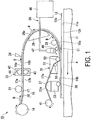
- FIG. 1 is a diagram schematically illustrating an outline configuration of a device for automatically layering prepreg sheets according to a first embodiment of the present invention.
- FIG. 1 schematically illustrates a state in which a semi-cured prepreg sheet 18 forming a layered sheet 16 is layered on a top surface 12a of a layered body 12 put on a stage 11.
- a in FIG. 1 indicates the movement direction (referred to below as the "A direction") of the stage 11 during execution of a prepreg sheet layering process illustrated in FIG. 1 .
- B in FIG. 1 indicates the feeding direction (referred to below as the “feeding direction B") of the layered sheet 16.
- C1 indicates a first region (referred to below as “first region C1") cooled by a cooling unit 29 in the predetermined region.
- first region C1 indicates a region located between a first roller 52 and a second guide roller 28.
- the arrows illustrated below a nozzle 48 in FIG. 1 illustrate how the cooling unit 29 cools a release sheet 17.
- the device for automatically layering prepreg sheets 10 of the first embodiment includes the stage 11, a layered sheet winding roller 14, a first guide roller 21, a layered sheet feeding unit 23, a cutter 24, a first guide member 26, the second guide roller 28, the cooling unit 29 which is a temperature gradient formation unit, a compactor 31, a support member 33, a pressing roller 36, a second guide member 37, and a release sheet recovery roller 41.
- the stage 11 is disposed on a base (not illustrated).
- the stage 11 is capable of moving in the A direction and the opposite direction to the A direction.
- the stage 11 is a flat surface and has a layered body putting surface 11a on which the layered body 12 is put.
- the layered body 12 is a layered body in which one or more semi-cured prepreg sheets are layered.
- the layered body 12 has the top surface 12a to which the semi-cured prepreg sheet 18 forming the layered sheet 16 is attached.
- the layered body 12 is put on the stage 11 such that a bottom surface 12b of the layered body 12 comes into contact with the layered body putting surface 11a.
- a layered sheet winding roller 14 is arranged upstream from the first guide roller 21.
- the layered sheet 16 is wound onto the layered sheet winding roller 14.
- the layered sheet 16 includes the release sheet 17 and the semi-cured prepreg sheet 18.
- the release sheet 17 has one surface 17a to which the semi-cured prepreg sheet 18 is attached, and the other surface 17b which is on the opposite side to the one surface 17a and is pressed by the first roller 52 to be described below.
- release paper can be used as the release sheet 17.
- the prepreg sheet 18 has one surface 18a which faces the top surface 12a of the layered body 12, and the other surface 18b which is on the opposite side to the one surface 18a and is attached to the one surface 17a of the release sheet 17.
- the prepreg sheet 18 includes a fiber sheet (not illustrated) and a semi-cured resin with which the fiber sheet is impregnated.
- a fiber sheet not illustrated
- a semi-cured resin with which the fiber sheet is impregnated for example, glass cloth, carbon fiber, or the like can be used as the fiber sheet.
- the resin forming the prepreg sheet 18 for example, it is possible to use a heat-curable resin, an ultraviolet-curable resin, or the like in a semi-cured state.
- a heat-curable resin it is possible to use, for example, acrylic resins, urea resins, melamine resins, phenol resins, epoxy resins, unsaturated polyesters, alkyd resins, urethane resins, ebonite, or the like.
- the first guide roller 21 is arranged between the layered sheet winding roller 14 and the layered sheet feeding unit 23.
- the roller surface of the first guide roller 21 comes into contact with the one surface 18a of the prepreg sheet 18.
- the first guide roller 21 is a roller for guiding the layered sheet 16 drawn out from the layered sheet winding roller 14 between a first feeding roller 43 and a second feeding roller 44 to be described below.
- the layered sheet feeding unit 23 is arranged between the first guide roller 21 and the cutter 24.
- the layered sheet feeding unit 23 includes a feeding unit main body 42, the first feeding roller 43, and the second feeding roller 44.
- the feeding unit main body 42 incorporates a rotary driving unit which independently rotates the first and second feeding rollers 43 and 44.
- the feeding unit main body 42 rotatably supports the first and second feeding rollers 43 and 44.
- the first feeding roller 43 is arranged directly below the layered sheet 16. The roller surface of the first feeding roller 43 comes into contact with the other surface 17b of the release sheet 17 forming the layered sheet 16.
- the second feeding roller 44 is arranged directly above the layered sheet 16.
- the roller surface of the second feeding roller 44 comes into contact with the one surface 18a of the prepreg sheet 18 forming the layered sheet 16.
- the layered sheet 16 drawn out from the layered sheet winding roller 14 is interposed between the first and second feeding rollers 43 and 44.
- the layered sheet 16 is fed in the B direction by the first and second feeding rollers 43 and 44 rotating in the direction illustrated by the arrows in FIG. 1 .
- the fed layered sheet 16 reaches a guide surface 26a of the first guide member 26.
- the cutter 24 is arranged so as to be able to cut the layered sheet 16 located between the layered sheet feeding unit 23 and the first guide member 26.
- the cutter 24 cuts the layered sheet 16 to be inserted to a desired length.
- the first guide member 26 is arranged downstream from the cutter 24.
- the first guide member 26 has the curved guide surface 26a.
- the first guide member 26 brings the other surface 17b of the release sheet 17 forming the layered sheet 16 fed by the layered sheet feeding unit 23 into contact with the guide surface 26a and reverses the top and bottom surfaces of the layered sheet 16 by guiding the layered sheet 16 along the curved guide surface 26a.
- the one surface 18a of the prepreg sheet 18 facing upward is made to face downward after passing through the first guide member 26. For this reason, the one surface 18a of the prepreg sheet 18 and the top surface 12a of the layered body 12 face each other.
- the second guide roller 28 is arranged between the nozzle 48 forming the cooling unit 29 and the first guide member 26.
- the second guide roller 28 has a roller surface coming into contact with the other surface 17b of the release sheet 17 forming the layered sheet 16.
- the second guide roller 28 guides the layered sheet 16 such that the one surface 18a of the prepreg sheet 18 forming the layered sheet 16 approaches the top surface 12a of the layered body 12.
- the cooling unit 29 has a cooler 46, a pipe 47, and the nozzle 48.
- the cooler 46 is a device for generating cold air by cooling air.
- the pipe 47 is a line for transporting cold air by the cooler 46 to the nozzle 48.
- the nozzle 48 is arranged above the release sheet 17 of the layered sheet 16 located in the first region C1.
- the nozzle 48 is arranged to be separated from the release sheet 17.
- the nozzle 48 blows cold air to the release sheet 17 from the other surface 17b side of the release sheet 17 when the prepreg sheet 18 is attached to the top surface 12a of the layered body 12.
- the cooling unit 29 configured as described above is arranged upstream from the first roller 52 which presses and layers the semi-cured prepreg sheet 18 on the top surface 12a of the layered body 12.
- the cooling unit 29 functions as a temperature gradient formation unit forming a temperature gradient (for example, a temperature gradient of approximately 1 to 2°C with respect to a reference temperature) in which the temperature is lowered in a direction from the one surface 18a of the semi-cured prepreg sheet 18 layered on the top surface 12a of the layered body 12 toward the other surface 17b of the release sheet 17, in the first region C1 of the layered sheet 16.
- a temperature gradient for example, a temperature gradient of approximately 1 to 2°C with respect to a reference temperature
- the temperature is lowered in the direction from the one surface 18a of the semi-cured prepreg sheet 18 layered on the top surface 12a of the layered body 12 toward the other surface 17b of the release sheet 17 in the layered sheet 16 located in the first region C1 arranged between the first roller 52 and the second guide roller 28 and upstream from the first roller 52 suppresses the decrease in the temperature on the one surface 18a side of the semi-cured prepreg sheet 18 and makes it possible to decrease the temperature in the vicinity of the interface between the other surface 18b of the semi-cured prepreg sheet 18 and the one surface 17a of the release sheet 17.
- the release sheet 17 can be easily peeled off from the semi-cured prepreg sheet 18.
- forming the above-described temperature gradient in a portion of the layered sheet 16 corresponding to the first region C1 makes it possible to further suppress the misalignment of the layered body 12 due to the poor releasability of the release sheet 17 in comparison with a case where, for example, the temperature gradient is formed in the layered sheet 16 by line contact using a roller.
- the compactor 31 is capable of moving in the vertical direction (the up and down direction).
- the compactor 31 includes a compactor body 51, the first roller 52, and a second roller 53.
- the compactor body 51 rotatably supports the first and second rollers 52 and 53 and incorporates a rotation driving unit (not illustrated) which independently rotates the first and second rollers 52 and 53.
- the first roller 52 is arranged upstream from the installation position of the second roller 53.
- the first roller 52 is arranged so as to protrude downward from the lower end of the compactor body 51. Due to this, as illustrated in FIG. 1 , when the compactor body 51 moves downward, the roller surface of the first roller 52 comes into contact with the other surface 17b of the release sheet 17 and presses the prepreg sheet 18 against the top surface 12a of the layered body 12 via the release sheet 17. At this time, the prepreg sheet 18 is layered on (attached to) the top surface 12a of the layered body 12 by moving the stage 11 in the A direction 12.
- the second roller 53 is arranged downstream from the installation position of the first roller 52.
- the second roller 53 is a roller with a smaller diameter than the first roller 52.
- the second roller 53 is arranged so as to not protrude from the lower end of the compactor body 51 and to allow the release sheet 17 to be guided in a direction in which the release sheet 17 is peeled off from the semi-cured prepreg sheet 18 layered on the top surface 12a of the layered body 12.
- the second roller 53 is a roller for peeling off the release sheet 17 from the semi-cured prepreg sheet 18 layered on the top surface 12a of the layered body 12.
- the support member 33 is arranged downstream from the compactor 31.
- the support member 33 is capable of moving in the up and down direction.
- a rotation driving unit (not illustrated) which rotates the pressing roller 36 is incorporated in the support member 33.
- the pressing roller 36 is provided in the support member 33 so as to protrude from the lower end of the support member 33.
- the pressing roller 36 has a roller surface.
- the roller surface of the pressing roller 36 comes into contact with the other surface 18b of the semi-cured prepreg sheet 18 which has passed the first roller 52 and layered.
- the pressing roller 36 is a roller for pressing the prepreg sheet 18 against the layered body 12.
- the second guide member 37 is provided on the upper end of the support member 33.
- the upper section of the second guide member 37 has a curved shape.
- the upper section of the second guide member 37 has a guide surface 37a which comes into contact with the one surface 17a of the release sheet 17 which has passed the second roller 53 and guides the release sheet 17 to a release sheet recovery roller 41.
- the release sheet recovery roller 41 is arranged downstream from the second guide member 37.
- the release sheet recovery roller 41 is a roller for recovering the release sheet 17 by winding the release sheet 17 which has passed the second guide member 37.
- the device for automatically layering prepreg sheets of the first embodiment includes the cooling unit 29 (a temperature gradient formation unit) which cools the release sheet 17 from the other surface 17b side of the release sheet 17 so as to form a temperature gradient (in which the temperature is lowered in the direction from the one surface 18a of the semi-cured prepreg sheet 18 layered on the top surface 12a of the layered body 12 toward the other surface 17b of the release sheet 17) in the first region C1 of the layered sheet 16 (the predetermined region in the first embodiment) which is located upstream from the first roller 52.
- the cooling unit 29 a temperature gradient formation unit
- the release sheet 17 can be easily peeled off from the semi-cured prepreg sheet 18.
- the productivity of the semi-cured prepreg layered body can be improved since it is possible to suppress the misalignment of the layered body 12 (in other words, of the semi-cured prepreg layered body under manufacturing) due to the poor releasability of the release sheet 17.
- forming the above-described temperature gradient in the layered sheet 16 corresponding to the first region C1 makes it possible to further suppress the misalignment of the layered body 12 due to the poor releasability of the release sheet 17 in comparison with a case where, for example, the temperature gradient is formed in the layered sheet 16 by line contact using a roller.
- the cooling unit 29 is able to form a temperature gradient in which the temperature is lowered in the direction from the one surface 18a of the semi-cured prepreg sheet 18 toward the other surface 17b of the release sheet 17, and the cooling unit 29 is not limited to the configuration illustrated in FIG. 1 .
- the layered body 12 is put on the layered body putting surface 11a of the stage 11. At this time, the layered body 12 is arranged such that the layered body putting surface 11a comes into contact with the bottom surface 12b of the layered body 12.
- the layered sheet 16 wound by the layered sheet winding roller 14 is fed in the B direction by the layered sheet feeding unit 23.
- the fed layered sheet 16 is guided to the guide surface 26a of the first guide member 26 so that the one surface 18a of the prepreg sheet 18 faces the top surface 12a of the layered body 12.
- a temperature gradient is formed in the first region C1 of the layered sheet 16 located upstream from the first roller 52 such that the temperature is lowered in the direction from the one surface 18a of the semi-cured prepreg sheet 18 layered on the top surface 12a of the layered body 12 toward the other surface 17b of the release sheet 17 (a temperature gradient formation step).
- the release sheet 17 located in the first region C1 is cooled by blowing cold air to the release sheet 17 from the other surface 17b side of the release sheet 17, and a temperature gradient is formed in which the temperature is lowered in the direction from the one surface 18a of the semi-cured prepreg sheet 18 layered on the top surface 12a of the layered body 12 toward the other surface 17b of the release sheet 17.
- the layered sheet 16 including the cooled release sheet 17 is fed between the roller surface of the first roller 52 and the top surface 12a of the layered body 12.
- the semi-cured prepreg sheet 18 forming the layered sheet 16 is layered on the top surface 12a of the layered body 12 formed of one or more layers of semi-cured prepreg sheets (layering step).
- the release sheet 17 is peeled off from the semi-cured prepreg sheet 18 layered on the top surface 12a of the layered body 12 using the second roller 53 arranged downstream from the first roller 52 (peeling step).
- a temperature gradient has been formed in which the temperature is lowered in the direction from the one surface 18a of the semi-cured prepreg sheet 18 layered on the top surface 12a of the layered body 12 toward the other surface 17b of the release sheet 17. Due to this, in addition to suppressing a decrease in temperature on the one surface 18a side of the semi-cured prepreg sheet 18, it is possible to decrease the temperature in the vicinity of the interface between the other surface 18b of the semi-cured prepreg sheet 18 and the one surface 17a of the release sheet 17.
- the release sheet 17 can be easily peeled off from the semi-cured prepreg sheet 18.
- the productivity of the semi-cured prepreg layered body can be improved since it is possible to suppress the misalignment of the layered body 12 (in other words, of the semi-cured prepreg layered body under manufacturing) due to difficulty in peeling off the release sheet 17.
- forming the above-described temperature gradient in the layered sheet 16 corresponding to the first region C1 makes it possible to further suppress the misalignment of the layered body 12 due to difficulty in peeling off the release sheet 16 in comparison with a case where, for example, a temperature gradient is formed in the layered sheet 16 by line contact using a roller.
- the layered sheet 16 is cut by the cutter 24 to a desired length (the same length as the layered body 12) and the semi-cured prepreg sheet 18 is layered so as to cover the top surface 12a of the layered body 12.
- a semi-cured prepreg layered body including the layered body 12 and at least one semi-cured prepreg sheet 18 layered on the layered body 12 is manufactured.
- a completely cured prepreg layered body is manufactured by completely curing the prepreg sheets forming the semi-cured prepreg layered body.
- the method for layering prepreg sheets of the first embodiment includes, before the layering step of layering the semi-cured prepreg sheet 18 forming the layered sheet 16 on the top surface 12a of the layered body 12 formed of one or more layers of semi-cured prepreg sheets, a temperature gradient formation step of forming a temperature gradient in which the temperature is lowered in the direction from the one surface 18a of the semi-cured prepreg sheet 18 layered on the top surface 12a of the layered body 12 toward the other surface 17b of the release sheet 17 in the first region C1 of the layered sheet 16 located upstream from the first roller 52.
- the release sheet 17 can be easily peeled off from the semi-cured prepreg sheet 18.
- the productivity of the semi-cured prepreg layered body can be improved since it is possible to suppress the misalignment of the layered body 12 (in other words, of the semi-cured prepreg layered body under manufacturing) due to the poor releasability of the release sheet 17.
- forming the above-described temperature gradient in a portion of the layered sheet 16 corresponding to the first region C1 makes it possible to further suppress the misalignment of the layered body 12 due to the poor releasability of the release sheet 17 in comparison with a case where, for example, the temperature gradient is formed in the layered sheet 16 by line contact using a roller.
- FIG. 2 is a diagram schematically illustrating an outline configuration of a device for automatically layering prepreg sheets according to a second embodiment of the present invention.
- the same reference numerals are used for constituent components which are the same as in the device for automatically layering prepreg sheets 10 of the first embodiment illustrated in FIG. 1 .
- FIG. 2 the arrows illustrated between a first heating unit 61 and the prepreg sheet 18 illustrate how the first heating unit 61 heats the prepreg sheet 18.
- a device for automatically layering prepreg sheets 60 of the second embodiment has the same configuration as the device for automatically layering prepreg sheets 10 of the first embodiment except that, the first heating unit 61 is further included in the device for automatically layering prepreg sheets 10.
- the second region C2 illustrated in FIG. 2 is a part of the predetermined region and illustrates a region (upstream from the first region C1) between the first guide member 26 and the second guide roller 28.
- the predetermined region of the second embodiment is formed of the first and second regions C1 and C2 which are different.
- the first heating unit 61 is arranged so as to face the one surface 18a of the semi-cured prepreg sheet 18 located in the second region.
- the first heating unit 61 is arranged to be separated from the one surface 18a of the prepreg sheet 18.
- the first heating unit 61 heats the semi-cured prepreg sheet 18 indirectly from the one surface 18a side of the semi-cured prepreg sheet 18.
- a heater can be used as the first heating unit 61.
- the device for automatically layering prepreg sheets of the second embodiment includes the first heating unit 61 which heats the semi-cured prepreg sheet 18 from the one surface 18a side of the semi-cured prepreg sheet 18 located in the second region C2 arranged upstream from the first region C1. Due to this, it is possible to form a temperature gradient (for example, a temperature gradient of approximately 1 to 2°C with respect to a reference temperature) in which the temperature is lowered in the direction from the one surface 18a of the semi-cured prepreg sheet 18 toward the other surface 17b of the release sheet 17.
- a temperature gradient for example, a temperature gradient of approximately 1 to 2°C with respect to a reference temperature
- the method for layering prepreg sheets of the second embodiment using the device for automatically layering prepreg sheets 60 configured as described above is the same as the method for layering prepreg sheets of the first embodiment except that, in the temperature gradient formation step, the semi-cured prepreg sheet 18 is heated from the one surface 18a side of the semi-cured prepreg sheet 18 located in the second region C2.
- the first heating unit 61 may be arranged so as to heat the prepreg sheet 18 located on the opposite side to the release sheet 17 cooled by the cooling unit 29 (in other words, so that the first region C1 and the second region C2 match).
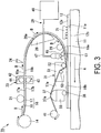
- FIG. 3 is a diagram schematically illustrating an outline configuration of a device for automatically layering prepreg sheets according to a third embodiment of the present invention.
- the same reference numerals are used for constituent components which are the same as in the device for automatically layering prepreg sheets 10 of the first embodiment illustrated in FIG. 1 .
- FIG. 3 the arrows illustrated between a second heating unit 71 and the layered body 12 illustrate how the second heating unit 71 heats the layered body 12.
- the device for automatically layering prepreg sheets 70 of the third embodiment has the same configuration as the device for automatically layering prepreg sheets 10 of the first embodiment except that the second heating unit 71 is further included in the device for automatically layering prepreg sheets 10 of the first embodiment.
- the second heating unit 71 is arranged facing the top surface 12a of the layered body 12 so as to be able to heat the layered body 12 located upstream from the first roller 52.
- the second heating unit 71 is arranged to be separated from the top surface 12a of the layered body 12.
- the second heating unit 71 heats the layered body 12 indirectly from the top surface 12a side of the layered body 12.
- a heater can be used as the second heating unit 71.
- providing the second heating unit 71 which heats the layered body 12 located upstream from the first roller 52 makes it possible to improve the adhesion between the top surface 12a of the layered body 12 and the one surface 18a of the semi-cured prepreg sheet 18.
- the device for automatically layering prepreg sheets 70 of the third embodiment configured as described above can obtain the same effects as the device for automatically layering prepreg sheets 10 of the first embodiment.
- the method for layering prepreg sheets of third embodiment using the device for automatically layering prepreg sheets 70 configured as described above is the same as the method for layering prepreg sheets of the first embodiment except that, in the temperature gradient formation step, the layered body 12 located upstream from the first roller 52 is heated.
- the device for automatically layering prepreg sheets 70 of the third embodiment may include the first heating unit 61 described in the second embodiment.
- the present invention can be applied to a device for automatically layering prepreg sheets and a method for layering prepreg sheets which form a prepreg layered body by layering a plurality of semi-cured prepreg sheets, each of the semi-cured prepreg sheets being formed of a fiber sheet impregnated with resin.
Landscapes
- Engineering & Computer Science (AREA)
- Mechanical Engineering (AREA)
- Chemical & Material Sciences (AREA)
- Composite Materials (AREA)
- Robotics (AREA)
- Physics & Mathematics (AREA)
- Health & Medical Sciences (AREA)
- Oral & Maxillofacial Surgery (AREA)
- Thermal Sciences (AREA)
- Reinforced Plastic Materials (AREA)
- Moulding By Coating Moulds (AREA)
- Casting Or Compression Moulding Of Plastics Or The Like (AREA)
Applications Claiming Priority (2)
| Application Number | Priority Date | Filing Date | Title |
|---|---|---|---|
| JP2013230373A JP6288495B2 (ja) | 2013-11-06 | 2013-11-06 | プリプレグシート自動積層装置、及びプリプレグシート積層方法 |
| PCT/JP2014/079355 WO2015068734A1 (ja) | 2013-11-06 | 2014-11-05 | プリプレグシート自動積層装置、及びプリプレグシート積層方法 |
Publications (3)
| Publication Number | Publication Date |
|---|---|
| EP3042754A1 EP3042754A1 (en) | 2016-07-13 |
| EP3042754A4 EP3042754A4 (en) | 2016-11-02 |
| EP3042754B1 true EP3042754B1 (en) | 2020-10-07 |
Family
ID=53041511
Family Applications (1)
| Application Number | Title | Priority Date | Filing Date |
|---|---|---|---|
| EP14860804.5A Active EP3042754B1 (en) | 2013-11-06 | 2014-11-05 | Device for automatically layering prepreg sheets and method for layering prepreg sheets |
Country Status (7)
| Country | Link |
|---|---|
| US (1) | US9993979B2 (enExample) |
| EP (1) | EP3042754B1 (enExample) |
| JP (1) | JP6288495B2 (enExample) |
| CN (1) | CN105612045B (enExample) |
| BR (1) | BR112016007532A2 (enExample) |
| CA (1) | CA2926333C (enExample) |
| WO (1) | WO2015068734A1 (enExample) |
Families Citing this family (8)
| Publication number | Priority date | Publication date | Assignee | Title |
|---|---|---|---|---|
| GB201511706D0 (en) | 2015-07-03 | 2015-08-19 | Composite Technology & Applic Ltd | A Method Of Manufacturing A Composite Component |
| KR102087409B1 (ko) * | 2015-11-11 | 2020-03-11 | 주식회사 엘지화학 | 프리프레그, 이를 이용한 복합재 및 이의 제조 방법 |
| FR3051709B1 (fr) | 2016-05-24 | 2019-01-25 | Airbus Helicopters | Tete de depose d'un ruban de fibres impregnees, et dispositif de placement d'un tel ruban |
| TWI645950B (zh) * | 2017-12-29 | 2019-01-01 | 宏茂科技股份有限公司 | Method for removing semi-cured resin |
| KR102124532B1 (ko) * | 2018-10-02 | 2020-06-18 | 주식회사 무창에프엔지 | 에어식 필름 부착장치 |
| JP2020132360A (ja) * | 2019-02-20 | 2020-08-31 | 三菱重工業株式会社 | スプライス装置、及び複合材自動積層装置 |
| JP2020131623A (ja) | 2019-02-22 | 2020-08-31 | 三菱重工業株式会社 | 複合材自動積層装置 |
| EP3974181A1 (en) | 2020-09-28 | 2022-03-30 | Kuraray Europe GmbH | Composite films with an obscuration area |
Citations (1)
| Publication number | Priority date | Publication date | Assignee | Title |
|---|---|---|---|---|
| US20080023130A1 (en) * | 2006-07-31 | 2008-01-31 | Airbus Espana, S.L. | Tool and process for manufacturing pieces of composite materials outside an autoclave |
Family Cites Families (16)
| Publication number | Priority date | Publication date | Assignee | Title |
|---|---|---|---|---|
| US5201979A (en) * | 1987-05-08 | 1993-04-13 | Research Association For New Technology Development Of High Performance Polymer | Method of manufacturing a sheet-prepreg reinforced with fibers |
| DE4130269C2 (de) * | 1990-09-13 | 1996-05-23 | Toshiba Machine Co Ltd | Verfahren und Vorrichtung zum Herstellen laminierter Prepreg-Teile |
| JPH05269881A (ja) * | 1992-01-29 | 1993-10-19 | Toshiba Mach Co Ltd | プリプレグ積層材の製造方法及びその製造装置 |
| JPH10272896A (ja) * | 1997-03-28 | 1998-10-13 | Dainippon Printing Co Ltd | 曲面転写方法 |
| JP4170781B2 (ja) * | 2003-01-17 | 2008-10-22 | 松下電器産業株式会社 | 基板の製造方法 |
| US7282107B2 (en) * | 2003-08-22 | 2007-10-16 | The Boeing Company | Multiple head automated composite laminating machine for the fabrication of large barrel section components |
| JP4218519B2 (ja) * | 2003-12-26 | 2009-02-04 | 戸田工業株式会社 | 磁界アンテナ、それを用いて構成したワイヤレスシステムおよび通信システム |
| JP2005297513A (ja) * | 2004-04-16 | 2005-10-27 | Fuji Heavy Ind Ltd | 自動積層装置 |
| JP2005329593A (ja) * | 2004-05-19 | 2005-12-02 | Fuji Heavy Ind Ltd | 自動積層装置 |
| JP2006281548A (ja) | 2005-03-31 | 2006-10-19 | Fuji Heavy Ind Ltd | 可視光硬化性繊維強化樹脂複合材の成形方法 |
| JP2007030336A (ja) * | 2005-07-27 | 2007-02-08 | Mitsubishi Heavy Ind Ltd | 繊維強化プラスチックの積層成形方法及び積層成形装置 |
| JP2008238809A (ja) * | 2007-02-28 | 2008-10-09 | Toray Ind Inc | 積層体の製造方法 |
| JP5422439B2 (ja) * | 2010-02-26 | 2014-02-19 | 三菱重工業株式会社 | プリプレグ積層ヘッド及びこれを備えたプリプレグ自動積層装置 |
| JP5439225B2 (ja) | 2010-02-26 | 2014-03-12 | 三菱重工業株式会社 | プリプレグ積層ヘッド及びこれを備えたプリプレグ自動積層装置 |
| US20130059125A1 (en) * | 2011-09-01 | 2013-03-07 | Honda Motor Co., Ltd. | Manufacturing apparatus and manufacturing method of composite structural member |
| CN102776299A (zh) * | 2012-07-26 | 2012-11-14 | 张放 | 在直贴转移膜超纤革表面用离型纸压纹的表面整饰方法 |
-
2013
- 2013-11-06 JP JP2013230373A patent/JP6288495B2/ja active Active
-
2014
- 2014-11-05 EP EP14860804.5A patent/EP3042754B1/en active Active
- 2014-11-05 WO PCT/JP2014/079355 patent/WO2015068734A1/ja not_active Ceased
- 2014-11-05 BR BR112016007532A patent/BR112016007532A2/pt not_active IP Right Cessation
- 2014-11-05 CN CN201480055558.8A patent/CN105612045B/zh not_active Expired - Fee Related
- 2014-11-05 CA CA2926333A patent/CA2926333C/en not_active Expired - Fee Related
- 2014-11-05 US US15/026,489 patent/US9993979B2/en active Active
Patent Citations (1)
| Publication number | Priority date | Publication date | Assignee | Title |
|---|---|---|---|---|
| US20080023130A1 (en) * | 2006-07-31 | 2008-01-31 | Airbus Espana, S.L. | Tool and process for manufacturing pieces of composite materials outside an autoclave |
Also Published As
| Publication number | Publication date |
|---|---|
| US20160243769A1 (en) | 2016-08-25 |
| EP3042754A1 (en) | 2016-07-13 |
| CA2926333A1 (en) | 2015-05-14 |
| US9993979B2 (en) | 2018-06-12 |
| EP3042754A4 (en) | 2016-11-02 |
| JP2015089647A (ja) | 2015-05-11 |
| BR112016007532A2 (pt) | 2017-08-01 |
| CA2926333C (en) | 2018-01-02 |
| JP6288495B2 (ja) | 2018-03-07 |
| WO2015068734A1 (ja) | 2015-05-14 |
| CN105612045A (zh) | 2016-05-25 |
| CN105612045B (zh) | 2017-09-29 |
Similar Documents
| Publication | Publication Date | Title |
|---|---|---|
| EP3042754B1 (en) | Device for automatically layering prepreg sheets and method for layering prepreg sheets | |
| KR102899957B1 (ko) | 박층 테이프의 자동 적층 방법 및 장치 | |
| JP5668874B2 (ja) | プリフォームの製造方法及び繊維強化樹脂成形品の製造方法 | |
| EP2489498B1 (en) | Method and device for manufacturing beam member | |
| JP5937894B2 (ja) | 複合材ストリンガーの連続プリフォーム装置 | |
| JPWO2007102573A1 (ja) | 強化繊維成形体の製造方法および製造装置 | |
| JP2008213311A (ja) | 段階状の断面厚さを有する複合材の連続成形方法 | |
| CN109228408B (zh) | 纤维强化的树脂基材或树脂成形体的制造方法以及该制造方法中使用的塑化吐出机 | |
| JP2007001298A (ja) | プリフォームの製造方法およびプリフォームの製造装置 | |
| JP5646089B2 (ja) | プリフォームの製造方法および繊維強化プラスチック成形体の製造方法 | |
| JP2010023449A (ja) | 繊維強化プラスチックの製造方法 | |
| KR20140087010A (ko) | 플라스틱 성형 부품의 제조 공정 | |
| JP6935620B2 (ja) | 薄層プリプレグテープの自動積層方法及び装置 | |
| EP3466631B1 (en) | Method and apparatus for manufacturing composite material | |
| JP2011057767A (ja) | 繊維強化複合材用プリフォームの製造方法と製造装置 | |
| JP2020082723A (ja) | 連続圧縮成形プロセスを使用して形成される、多孔質コアを有する複合積層構造 | |
| JP4873879B2 (ja) | 多軸多層補強シートの製造方法及び製造装置 | |
| JP2012016939A (ja) | 複合材成形品の製造方法 | |
| JP7175820B2 (ja) | プリプレグ成形方法 | |
| JPH0818379B2 (ja) | プリプレグの積層方法及びその装置 | |
| TW200404845A (en) | Paper-free prepreg |
Legal Events
| Date | Code | Title | Description |
|---|---|---|---|
| PUAI | Public reference made under article 153(3) epc to a published international application that has entered the european phase |
Free format text: ORIGINAL CODE: 0009012 |
|
| 17P | Request for examination filed |
Effective date: 20160404 |
|
| AK | Designated contracting states |
Kind code of ref document: A1 Designated state(s): AL AT BE BG CH CY CZ DE DK EE ES FI FR GB GR HR HU IE IS IT LI LT LU LV MC MK MT NL NO PL PT RO RS SE SI SK SM TR |
|
| AX | Request for extension of the european patent |
Extension state: BA ME |
|
| A4 | Supplementary search report drawn up and despatched |
Effective date: 20161004 |
|
| RIC1 | Information provided on ipc code assigned before grant |
Ipc: B29C 43/18 20060101ALI20160927BHEP Ipc: B29C 70/06 20060101AFI20160927BHEP Ipc: B29K 105/08 20060101ALI20160927BHEP |
|
| DAX | Request for extension of the european patent (deleted) | ||
| GRAP | Despatch of communication of intention to grant a patent |
Free format text: ORIGINAL CODE: EPIDOSNIGR1 |
|
| STAA | Information on the status of an ep patent application or granted ep patent |
Free format text: STATUS: GRANT OF PATENT IS INTENDED |
|
| RIC1 | Information provided on ipc code assigned before grant |
Ipc: B29C 43/18 20060101ALI20200504BHEP Ipc: B29K 105/08 20060101ALI20200504BHEP Ipc: B29C 70/06 20060101AFI20200504BHEP Ipc: B29C 70/38 20060101ALI20200504BHEP |
|
| INTG | Intention to grant announced |
Effective date: 20200602 |
|
| GRAS | Grant fee paid |
Free format text: ORIGINAL CODE: EPIDOSNIGR3 |
|
| GRAA | (expected) grant |
Free format text: ORIGINAL CODE: 0009210 |
|
| STAA | Information on the status of an ep patent application or granted ep patent |
Free format text: STATUS: THE PATENT HAS BEEN GRANTED |
|
| AK | Designated contracting states |
Kind code of ref document: B1 Designated state(s): AL AT BE BG CH CY CZ DE DK EE ES FI FR GB GR HR HU IE IS IT LI LT LU LV MC MK MT NL NO PL PT RO RS SE SI SK SM TR |
|
| REG | Reference to a national code |
Ref country code: GB Ref legal event code: FG4D |
|
| REG | Reference to a national code |
Ref country code: AT Ref legal event code: REF Ref document number: 1320690 Country of ref document: AT Kind code of ref document: T Effective date: 20201015 Ref country code: CH Ref legal event code: EP |
|
| REG | Reference to a national code |
Ref country code: IE Ref legal event code: FG4D |
|
| REG | Reference to a national code |
Ref country code: DE Ref legal event code: R096 Ref document number: 602014071094 Country of ref document: DE |
|
| REG | Reference to a national code |
Ref country code: NL Ref legal event code: MP Effective date: 20201007 |
|
| REG | Reference to a national code |
Ref country code: AT Ref legal event code: MK05 Ref document number: 1320690 Country of ref document: AT Kind code of ref document: T Effective date: 20201007 |
|
| PG25 | Lapsed in a contracting state [announced via postgrant information from national office to epo] |
Ref country code: GR Free format text: LAPSE BECAUSE OF FAILURE TO SUBMIT A TRANSLATION OF THE DESCRIPTION OR TO PAY THE FEE WITHIN THE PRESCRIBED TIME-LIMIT Effective date: 20210108 Ref country code: NL Free format text: LAPSE BECAUSE OF FAILURE TO SUBMIT A TRANSLATION OF THE DESCRIPTION OR TO PAY THE FEE WITHIN THE PRESCRIBED TIME-LIMIT Effective date: 20201007 Ref country code: PT Free format text: LAPSE BECAUSE OF FAILURE TO SUBMIT A TRANSLATION OF THE DESCRIPTION OR TO PAY THE FEE WITHIN THE PRESCRIBED TIME-LIMIT Effective date: 20210208 Ref country code: NO Free format text: LAPSE BECAUSE OF FAILURE TO SUBMIT A TRANSLATION OF THE DESCRIPTION OR TO PAY THE FEE WITHIN THE PRESCRIBED TIME-LIMIT Effective date: 20210107 Ref country code: FI Free format text: LAPSE BECAUSE OF FAILURE TO SUBMIT A TRANSLATION OF THE DESCRIPTION OR TO PAY THE FEE WITHIN THE PRESCRIBED TIME-LIMIT Effective date: 20201007 Ref country code: RS Free format text: LAPSE BECAUSE OF FAILURE TO SUBMIT A TRANSLATION OF THE DESCRIPTION OR TO PAY THE FEE WITHIN THE PRESCRIBED TIME-LIMIT Effective date: 20201007 |
|
| REG | Reference to a national code |
Ref country code: LT Ref legal event code: MG4D |
|
| PG25 | Lapsed in a contracting state [announced via postgrant information from national office to epo] |
Ref country code: SE Free format text: LAPSE BECAUSE OF FAILURE TO SUBMIT A TRANSLATION OF THE DESCRIPTION OR TO PAY THE FEE WITHIN THE PRESCRIBED TIME-LIMIT Effective date: 20201007 Ref country code: IS Free format text: LAPSE BECAUSE OF FAILURE TO SUBMIT A TRANSLATION OF THE DESCRIPTION OR TO PAY THE FEE WITHIN THE PRESCRIBED TIME-LIMIT Effective date: 20210207 Ref country code: LV Free format text: LAPSE BECAUSE OF FAILURE TO SUBMIT A TRANSLATION OF THE DESCRIPTION OR TO PAY THE FEE WITHIN THE PRESCRIBED TIME-LIMIT Effective date: 20201007 Ref country code: PL Free format text: LAPSE BECAUSE OF FAILURE TO SUBMIT A TRANSLATION OF THE DESCRIPTION OR TO PAY THE FEE WITHIN THE PRESCRIBED TIME-LIMIT Effective date: 20201007 Ref country code: BG Free format text: LAPSE BECAUSE OF FAILURE TO SUBMIT A TRANSLATION OF THE DESCRIPTION OR TO PAY THE FEE WITHIN THE PRESCRIBED TIME-LIMIT Effective date: 20210107 Ref country code: AT Free format text: LAPSE BECAUSE OF FAILURE TO SUBMIT A TRANSLATION OF THE DESCRIPTION OR TO PAY THE FEE WITHIN THE PRESCRIBED TIME-LIMIT Effective date: 20201007 Ref country code: ES Free format text: LAPSE BECAUSE OF FAILURE TO SUBMIT A TRANSLATION OF THE DESCRIPTION OR TO PAY THE FEE WITHIN THE PRESCRIBED TIME-LIMIT Effective date: 20201007 |
|
| PG25 | Lapsed in a contracting state [announced via postgrant information from national office to epo] |
Ref country code: HR Free format text: LAPSE BECAUSE OF FAILURE TO SUBMIT A TRANSLATION OF THE DESCRIPTION OR TO PAY THE FEE WITHIN THE PRESCRIBED TIME-LIMIT Effective date: 20201007 |
|
| REG | Reference to a national code |
Ref country code: CH Ref legal event code: PL |
|
| REG | Reference to a national code |
Ref country code: DE Ref legal event code: R097 Ref document number: 602014071094 Country of ref document: DE |
|
| PG25 | Lapsed in a contracting state [announced via postgrant information from national office to epo] |
Ref country code: SK Free format text: LAPSE BECAUSE OF FAILURE TO SUBMIT A TRANSLATION OF THE DESCRIPTION OR TO PAY THE FEE WITHIN THE PRESCRIBED TIME-LIMIT Effective date: 20201007 Ref country code: RO Free format text: LAPSE BECAUSE OF FAILURE TO SUBMIT A TRANSLATION OF THE DESCRIPTION OR TO PAY THE FEE WITHIN THE PRESCRIBED TIME-LIMIT Effective date: 20201007 Ref country code: MC Free format text: LAPSE BECAUSE OF FAILURE TO SUBMIT A TRANSLATION OF THE DESCRIPTION OR TO PAY THE FEE WITHIN THE PRESCRIBED TIME-LIMIT Effective date: 20201007 Ref country code: LU Free format text: LAPSE BECAUSE OF NON-PAYMENT OF DUE FEES Effective date: 20201105 Ref country code: LT Free format text: LAPSE BECAUSE OF FAILURE TO SUBMIT A TRANSLATION OF THE DESCRIPTION OR TO PAY THE FEE WITHIN THE PRESCRIBED TIME-LIMIT Effective date: 20201007 Ref country code: SM Free format text: LAPSE BECAUSE OF FAILURE TO SUBMIT A TRANSLATION OF THE DESCRIPTION OR TO PAY THE FEE WITHIN THE PRESCRIBED TIME-LIMIT Effective date: 20201007 Ref country code: EE Free format text: LAPSE BECAUSE OF FAILURE TO SUBMIT A TRANSLATION OF THE DESCRIPTION OR TO PAY THE FEE WITHIN THE PRESCRIBED TIME-LIMIT Effective date: 20201007 Ref country code: CZ Free format text: LAPSE BECAUSE OF FAILURE TO SUBMIT A TRANSLATION OF THE DESCRIPTION OR TO PAY THE FEE WITHIN THE PRESCRIBED TIME-LIMIT Effective date: 20201007 |
|
| REG | Reference to a national code |
Ref country code: BE Ref legal event code: MM Effective date: 20201130 |
|
| PLBE | No opposition filed within time limit |
Free format text: ORIGINAL CODE: 0009261 |
|
| STAA | Information on the status of an ep patent application or granted ep patent |
Free format text: STATUS: NO OPPOSITION FILED WITHIN TIME LIMIT |
|
| PG25 | Lapsed in a contracting state [announced via postgrant information from national office to epo] |
Ref country code: CH Free format text: LAPSE BECAUSE OF NON-PAYMENT OF DUE FEES Effective date: 20201130 Ref country code: DK Free format text: LAPSE BECAUSE OF FAILURE TO SUBMIT A TRANSLATION OF THE DESCRIPTION OR TO PAY THE FEE WITHIN THE PRESCRIBED TIME-LIMIT Effective date: 20201007 Ref country code: LI Free format text: LAPSE BECAUSE OF NON-PAYMENT OF DUE FEES Effective date: 20201130 |
|
| 26N | No opposition filed |
Effective date: 20210708 |
|
| GBPC | Gb: european patent ceased through non-payment of renewal fee |
Effective date: 20210107 |
|
| PG25 | Lapsed in a contracting state [announced via postgrant information from national office to epo] |
Ref country code: AL Free format text: LAPSE BECAUSE OF FAILURE TO SUBMIT A TRANSLATION OF THE DESCRIPTION OR TO PAY THE FEE WITHIN THE PRESCRIBED TIME-LIMIT Effective date: 20201007 Ref country code: IT Free format text: LAPSE BECAUSE OF FAILURE TO SUBMIT A TRANSLATION OF THE DESCRIPTION OR TO PAY THE FEE WITHIN THE PRESCRIBED TIME-LIMIT Effective date: 20201007 Ref country code: IE Free format text: LAPSE BECAUSE OF NON-PAYMENT OF DUE FEES Effective date: 20201105 |
|
| PG25 | Lapsed in a contracting state [announced via postgrant information from national office to epo] |
Ref country code: GB Free format text: LAPSE BECAUSE OF NON-PAYMENT OF DUE FEES Effective date: 20210107 Ref country code: SI Free format text: LAPSE BECAUSE OF FAILURE TO SUBMIT A TRANSLATION OF THE DESCRIPTION OR TO PAY THE FEE WITHIN THE PRESCRIBED TIME-LIMIT Effective date: 20201007 |
|
| PGFP | Annual fee paid to national office [announced via postgrant information from national office to epo] |
Ref country code: DE Payment date: 20210929 Year of fee payment: 8 |
|
| PG25 | Lapsed in a contracting state [announced via postgrant information from national office to epo] |
Ref country code: IS Free format text: LAPSE BECAUSE OF FAILURE TO SUBMIT A TRANSLATION OF THE DESCRIPTION OR TO PAY THE FEE WITHIN THE PRESCRIBED TIME-LIMIT Effective date: 20210207 Ref country code: TR Free format text: LAPSE BECAUSE OF FAILURE TO SUBMIT A TRANSLATION OF THE DESCRIPTION OR TO PAY THE FEE WITHIN THE PRESCRIBED TIME-LIMIT Effective date: 20201007 Ref country code: MT Free format text: LAPSE BECAUSE OF FAILURE TO SUBMIT A TRANSLATION OF THE DESCRIPTION OR TO PAY THE FEE WITHIN THE PRESCRIBED TIME-LIMIT Effective date: 20201007 Ref country code: CY Free format text: LAPSE BECAUSE OF FAILURE TO SUBMIT A TRANSLATION OF THE DESCRIPTION OR TO PAY THE FEE WITHIN THE PRESCRIBED TIME-LIMIT Effective date: 20201007 |
|
| PG25 | Lapsed in a contracting state [announced via postgrant information from national office to epo] |
Ref country code: MK Free format text: LAPSE BECAUSE OF FAILURE TO SUBMIT A TRANSLATION OF THE DESCRIPTION OR TO PAY THE FEE WITHIN THE PRESCRIBED TIME-LIMIT Effective date: 20201007 |
|
| PG25 | Lapsed in a contracting state [announced via postgrant information from national office to epo] |
Ref country code: BE Free format text: LAPSE BECAUSE OF NON-PAYMENT OF DUE FEES Effective date: 20201130 |
|
| REG | Reference to a national code |
Ref country code: DE Ref legal event code: R119 Ref document number: 602014071094 Country of ref document: DE |
|
| PG25 | Lapsed in a contracting state [announced via postgrant information from national office to epo] |
Ref country code: DE Free format text: LAPSE BECAUSE OF NON-PAYMENT OF DUE FEES Effective date: 20230601 |
|
| PGFP | Annual fee paid to national office [announced via postgrant information from national office to epo] |
Ref country code: FR Payment date: 20250930 Year of fee payment: 12 |