EP3042754B1 - Device for automatically layering prepreg sheets and method for layering prepreg sheets - Google Patents
Device for automatically layering prepreg sheets and method for layering prepreg sheets Download PDFInfo
- Publication number
- EP3042754B1 EP3042754B1 EP14860804.5A EP14860804A EP3042754B1 EP 3042754 B1 EP3042754 B1 EP 3042754B1 EP 14860804 A EP14860804 A EP 14860804A EP 3042754 B1 EP3042754 B1 EP 3042754B1
- Authority
- EP
- European Patent Office
- Prior art keywords
- sheet
- semi
- layered
- prepreg
- roller
- Prior art date
- Legal status (The legal status is an assumption and is not a legal conclusion. Google has not performed a legal analysis and makes no representation as to the accuracy of the status listed.)
- Active
Links
- 238000000034 method Methods 0.000 title claims description 28
- 238000010438 heat treatment Methods 0.000 claims description 35
- 238000011144 upstream manufacturing Methods 0.000 claims description 28
- 238000001816 cooling Methods 0.000 claims description 26
- 230000015572 biosynthetic process Effects 0.000 claims description 25
- 239000000835 fiber Substances 0.000 claims description 15
- 229920005989 resin Polymers 0.000 claims description 15
- 239000011347 resin Substances 0.000 claims description 15
- 238000003825 pressing Methods 0.000 claims description 12
- 238000004519 manufacturing process Methods 0.000 description 14
- 239000000853 adhesive Substances 0.000 description 11
- 230000001070 adhesive effect Effects 0.000 description 11
- 238000004804 winding Methods 0.000 description 9
- 238000005056 compaction Methods 0.000 description 6
- 238000010586 diagram Methods 0.000 description 6
- 239000000463 material Substances 0.000 description 5
- 238000011084 recovery Methods 0.000 description 5
- 229920001187 thermosetting polymer Polymers 0.000 description 4
- 238000007664 blowing Methods 0.000 description 3
- 239000000470 constituent Substances 0.000 description 3
- 230000000694 effects Effects 0.000 description 3
- 238000010030 laminating Methods 0.000 description 3
- 230000005494 condensation Effects 0.000 description 2
- 238000009833 condensation Methods 0.000 description 2
- 238000009434 installation Methods 0.000 description 2
- 238000000465 moulding Methods 0.000 description 2
- 239000004925 Acrylic resin Substances 0.000 description 1
- 229920000178 Acrylic resin Polymers 0.000 description 1
- 229920000049 Carbon (fiber) Polymers 0.000 description 1
- 229920001875 Ebonite Polymers 0.000 description 1
- RRHGJUQNOFWUDK-UHFFFAOYSA-N Isoprene Chemical compound CC(=C)C=C RRHGJUQNOFWUDK-UHFFFAOYSA-N 0.000 description 1
- 229920000877 Melamine resin Polymers 0.000 description 1
- 229920001807 Urea-formaldehyde Polymers 0.000 description 1
- 229920000180 alkyd Polymers 0.000 description 1
- 238000013459 approach Methods 0.000 description 1
- 239000004917 carbon fiber Substances 0.000 description 1
- 239000002131 composite material Substances 0.000 description 1
- 238000007796 conventional method Methods 0.000 description 1
- 238000002788 crimping Methods 0.000 description 1
- 230000003247 decreasing effect Effects 0.000 description 1
- 239000003822 epoxy resin Substances 0.000 description 1
- 239000004744 fabric Substances 0.000 description 1
- 239000011521 glass Substances 0.000 description 1
- LNEPOXFFQSENCJ-UHFFFAOYSA-N haloperidol Chemical compound C1CC(O)(C=2C=CC(Cl)=CC=2)CCN1CCCC(=O)C1=CC=C(F)C=C1 LNEPOXFFQSENCJ-UHFFFAOYSA-N 0.000 description 1
- VNWKTOKETHGBQD-UHFFFAOYSA-N methane Chemical compound C VNWKTOKETHGBQD-UHFFFAOYSA-N 0.000 description 1
- 239000005011 phenolic resin Substances 0.000 description 1
- 229920000647 polyepoxide Polymers 0.000 description 1
- 238000003860 storage Methods 0.000 description 1
- 229920002803 thermoplastic polyurethane Polymers 0.000 description 1
- 229920006305 unsaturated polyester Polymers 0.000 description 1
Images

Classifications
-
- B—PERFORMING OPERATIONS; TRANSPORTING
- B29—WORKING OF PLASTICS; WORKING OF SUBSTANCES IN A PLASTIC STATE IN GENERAL
- B29C—SHAPING OR JOINING OF PLASTICS; SHAPING OF MATERIAL IN A PLASTIC STATE, NOT OTHERWISE PROVIDED FOR; AFTER-TREATMENT OF THE SHAPED PRODUCTS, e.g. REPAIRING
- B29C70/00—Shaping composites, i.e. plastics material comprising reinforcements, fillers or preformed parts, e.g. inserts
- B29C70/04—Shaping composites, i.e. plastics material comprising reinforcements, fillers or preformed parts, e.g. inserts comprising reinforcements only, e.g. self-reinforcing plastics
- B29C70/28—Shaping operations therefor
- B29C70/30—Shaping by lay-up, i.e. applying fibres, tape or broadsheet on a mould, former or core; Shaping by spray-up, i.e. spraying of fibres on a mould, former or core
- B29C70/38—Automated lay-up, e.g. using robots, laying filaments according to predetermined patterns
- B29C70/386—Automated tape laying [ATL]
- B29C70/388—Tape placement heads, e.g. component parts, details or accessories
-
- B—PERFORMING OPERATIONS; TRANSPORTING
- B29—WORKING OF PLASTICS; WORKING OF SUBSTANCES IN A PLASTIC STATE IN GENERAL
- B29C—SHAPING OR JOINING OF PLASTICS; SHAPING OF MATERIAL IN A PLASTIC STATE, NOT OTHERWISE PROVIDED FOR; AFTER-TREATMENT OF THE SHAPED PRODUCTS, e.g. REPAIRING
- B29C33/00—Moulds or cores; Details thereof or accessories therefor
- B29C33/56—Coatings, e.g. enameled or galvanised; Releasing, lubricating or separating agents
- B29C33/68—Release sheets
-
- B—PERFORMING OPERATIONS; TRANSPORTING
- B29—WORKING OF PLASTICS; WORKING OF SUBSTANCES IN A PLASTIC STATE IN GENERAL
- B29C—SHAPING OR JOINING OF PLASTICS; SHAPING OF MATERIAL IN A PLASTIC STATE, NOT OTHERWISE PROVIDED FOR; AFTER-TREATMENT OF THE SHAPED PRODUCTS, e.g. REPAIRING
- B29C35/00—Heating, cooling or curing, e.g. crosslinking or vulcanising; Apparatus therefor
- B29C35/02—Heating or curing, e.g. crosslinking or vulcanizing during moulding, e.g. in a mould
-
- B—PERFORMING OPERATIONS; TRANSPORTING
- B29—WORKING OF PLASTICS; WORKING OF SUBSTANCES IN A PLASTIC STATE IN GENERAL
- B29C—SHAPING OR JOINING OF PLASTICS; SHAPING OF MATERIAL IN A PLASTIC STATE, NOT OTHERWISE PROVIDED FOR; AFTER-TREATMENT OF THE SHAPED PRODUCTS, e.g. REPAIRING
- B29C35/00—Heating, cooling or curing, e.g. crosslinking or vulcanising; Apparatus therefor
- B29C35/16—Cooling
-
- B—PERFORMING OPERATIONS; TRANSPORTING
- B29—WORKING OF PLASTICS; WORKING OF SUBSTANCES IN A PLASTIC STATE IN GENERAL
- B29C—SHAPING OR JOINING OF PLASTICS; SHAPING OF MATERIAL IN A PLASTIC STATE, NOT OTHERWISE PROVIDED FOR; AFTER-TREATMENT OF THE SHAPED PRODUCTS, e.g. REPAIRING
- B29C70/00—Shaping composites, i.e. plastics material comprising reinforcements, fillers or preformed parts, e.g. inserts
- B29C70/04—Shaping composites, i.e. plastics material comprising reinforcements, fillers or preformed parts, e.g. inserts comprising reinforcements only, e.g. self-reinforcing plastics
- B29C70/06—Fibrous reinforcements only
-
- B—PERFORMING OPERATIONS; TRANSPORTING
- B29—WORKING OF PLASTICS; WORKING OF SUBSTANCES IN A PLASTIC STATE IN GENERAL
- B29C—SHAPING OR JOINING OF PLASTICS; SHAPING OF MATERIAL IN A PLASTIC STATE, NOT OTHERWISE PROVIDED FOR; AFTER-TREATMENT OF THE SHAPED PRODUCTS, e.g. REPAIRING
- B29C35/00—Heating, cooling or curing, e.g. crosslinking or vulcanising; Apparatus therefor
- B29C35/16—Cooling
- B29C2035/1658—Cooling using gas
-
- B—PERFORMING OPERATIONS; TRANSPORTING
- B29—WORKING OF PLASTICS; WORKING OF SUBSTANCES IN A PLASTIC STATE IN GENERAL
- B29K—INDEXING SCHEME ASSOCIATED WITH SUBCLASSES B29B, B29C OR B29D, RELATING TO MOULDING MATERIALS OR TO MATERIALS FOR MOULDS, REINFORCEMENTS, FILLERS OR PREFORMED PARTS, e.g. INSERTS
- B29K2101/00—Use of unspecified macromolecular compounds as moulding material
- B29K2101/10—Thermosetting resins
-
- B—PERFORMING OPERATIONS; TRANSPORTING
- B29—WORKING OF PLASTICS; WORKING OF SUBSTANCES IN A PLASTIC STATE IN GENERAL
- B29K—INDEXING SCHEME ASSOCIATED WITH SUBCLASSES B29B, B29C OR B29D, RELATING TO MOULDING MATERIALS OR TO MATERIALS FOR MOULDS, REINFORCEMENTS, FILLERS OR PREFORMED PARTS, e.g. INSERTS
- B29K2105/00—Condition, form or state of moulded material or of the material to be shaped
- B29K2105/06—Condition, form or state of moulded material or of the material to be shaped containing reinforcements, fillers or inserts
- B29K2105/08—Condition, form or state of moulded material or of the material to be shaped containing reinforcements, fillers or inserts of continuous length, e.g. cords, rovings, mats, fabrics, strands or yarns
- B29K2105/0872—Prepregs
-
- B—PERFORMING OPERATIONS; TRANSPORTING
- B29—WORKING OF PLASTICS; WORKING OF SUBSTANCES IN A PLASTIC STATE IN GENERAL
- B29L—INDEXING SCHEME ASSOCIATED WITH SUBCLASS B29C, RELATING TO PARTICULAR ARTICLES
- B29L2031/00—Other particular articles
- B29L2031/30—Vehicles, e.g. ships or aircraft, or body parts thereof
- B29L2031/3076—Aircrafts
- B29L2031/3082—Fuselages
-
- B—PERFORMING OPERATIONS; TRANSPORTING
- B29—WORKING OF PLASTICS; WORKING OF SUBSTANCES IN A PLASTIC STATE IN GENERAL
- B29L—INDEXING SCHEME ASSOCIATED WITH SUBCLASS B29C, RELATING TO PARTICULAR ARTICLES
- B29L2031/00—Other particular articles
- B29L2031/30—Vehicles, e.g. ships or aircraft, or body parts thereof
- B29L2031/3076—Aircrafts
- B29L2031/3085—Wings
Definitions
- the present invention relates to a device for automatically layering prepreg sheets and a method for layering prepreg sheets which manufacture prepreg layered bodies formed by layering a plurality of semi-cured prepreg sheets, each of the semi-cured prepreg sheets being formed of a fiber sheet impregnated with resin.
- the completely cured prepreg layered bodies are each formed by layering a plurality of prepreg sheets (FRP sheets), each of the prepreg sheets being formed of a fiber sheet impregnated with resin, to form a semi-cured (incompletely cured) prepreg layered body and then completely curing the semi-cured prepreg layered body.
- FRP sheets prepreg sheets
- the fibers forming the fiber sheet described above extend in the same fiber direction.
- the fiber sheet has adhesiveness because an ultraviolet curable resin, a thermosetting resin, or the like in a semi-cured state (incompletely cured state) is used as the resin with which the fiber sheet is impregnated. For this reason, a release sheet is arranged on one surface of the prepreg sheet.
- the prepreg layered body in the semi-cured state described above is formed using a device for automatically layering prepreg sheets.
- the device for automatically layering prepreg sheets forms a semi-cured prepreg layered body by removing the release sheet from the semi-cured prepreg sheet and integrally layering a plurality of the prepreg sheets while the fiber directions of the fiber sheets are made to intersect each other.
- the resin forming the prepreg sheet is a thermosetting resin
- the air expands, which could lead to a further decrease in the adhesion between the prepreg sheets.
- the semi-cured prepreg sheets may be pulled by the release sheet such that the prepreg layered body (in other words, a layered body formed of one or more semi-cured prepreg sheets), which is in a semi-cured state under manufacturing floats up, or such that the position of the layered body is shifted from a predetermined position.
- the prepreg layered body in other words, a layered body formed of one or more semi-cured prepreg sheets
- the prepreg layered body (layered body) which has been misaligned under manufacturing is removed manually and the semi-cured prepreg sheet layering process is performed again. For this reason, the productivity of the semi-cured prepreg layered body is decreased.
- US-A-2008023130 discloses a device for automatically layering prepreg sheets and a method for layering prepreg sheets.
- JP 2006-281548A describes a conventional technique which can improve the adhesion between the semi-cured prepreg sheets.
- JP 2006-281548A discloses a technique in which a prepreg material (prepreg sheet) is fed and taken out from a cartridge, the tackiness (adhesiveness) is improved by heating through contact with a heated compaction roller, and the prepreg material is pressed and layered on a forming jig by the compaction roller.
- EP 1547753 A1 discloses a method and apparatus for molding the thermosetting composite material and the document specifically teaches to pull out a plurality of strip-prepreg members from respective prepreg rolls and to then layer the strip-prepreg members to form a layered sheet. Then, the so formed layered sheet or body is formed into an L-shape in a hot press unit and it is subsequently cooled in a cooling unit to stop the progression of thermosetting.
- JP 2005-297513 A discloses a laminating apparatus which also concerns the process of layering or laminating semi-cured prepreg sheet or tape on the surface of a body by heating and pressing the prepreg tape withdrawn from a storage.
- the applicator for the prepreg tape includes a front compaction roller for heating and pressurizing the tape and a rear compaction roller for cooling pressurization.
- the front compaction roller is used for molding by heating and pressing when laminating the prepreg tape.
- the compaction roller itself is heated to cure the prepreg tape.
- the adhesive force between the layered prepreg materials can be improved; however, it is harder to peel off the release sheet from the prepreg material since the adhesive force between the release sheet and the prepreg material is also improved.
- the semi-cured prepreg layered body (layered body) under manufacturing is misaligned with respect to a predetermined position, which may decrease the productivity of the semi-cured prepreg layered body.
- the present invention provides a device with the features of claim 1 for automatically layering prepreg sheets and a method with the features of claim 5 for layering prepreg sheets.
- Claim 1 discloses a first aspect of the present invention.
- the device includes the temperature gradient formation unit which forms a temperature gradient in the predetermined region of the layered sheet located upstream from the first roller such that the temperature is lowered in the direction from the one surface of the semi-cured prepreg sheet layered on the top surface of the layered body toward the other surface of the release sheet.
- This also makes it possible to suppress a decrease in the adhesive force of the one surface of the semi-cured prepreg sheet and to easily peel off the release sheet from the semi-cured prepreg sheet.
- the productivity of the semi-cured prepreg layered body can be improved.
- forming the above-described temperature gradient in a portion corresponding to the predetermined region of the layered sheet makes it possible to further suppress the misalignment of the layered body due to the poor releasability of the release sheet in comparison with a case where, for example, the temperature gradient is formed in the layered sheet by line contact using a roller.
- the predetermined region includes a first region
- the temperature gradient formation unit is a cooling unit which cools the release sheet from the other surface side of the release sheet located in the first region.
- the temperature is lowered on the other surface side of the release sheet using a cooling unit, which cools the release sheet from the other surface side of the release sheet located in the first region of the predetermined region, as the temperature gradient formation unit. Therefore, it is possible to form a temperature gradient in which the temperature is lowered in a direction from the one surface of the semi-cured prepreg sheet toward the other surface of the release sheet.
- the cooling unit may blow cold air to the other surface of the release sheet located in the first region.
- providing the cooling unit blowing cold air to the other surface of the release sheet located in the first region makes it possible to form a temperature gradient in which the temperature is lowered in a direction from one surface of the semi-cured prepreg sheet toward the other surface of the release sheet.
- the predetermined region may include a second region located upstream from the first region, and a first heating unit may be included which heats the semi-cured prepreg sheet from the one surface side of the semi-cured prepreg sheet located in the second region.
- providing the first heating unit which heats the semi-cured prepreg sheet from the one surface side of the semi-cured prepreg sheet located in the second region arranged upstream from the first region makes it possible to form a temperature gradient in which the temperature is lowered in a direction from one surface of the semi-cured prepreg sheet toward the other surface of the release sheet.
- cooling unit and the first heating unit that form a temperature gradient in which the temperature is lowered in a direction from one surface of the semi-cured prepreg sheet toward the other surface of the release sheet makes it possible to improve the adhesive force between the top surface of the layered body and one surface of the semi-cured prepreg sheet.
- a second heating unit which heats the layered body located upstream from the first roller may be included.
- providing the second heating unit which heats the layered body located upstream from the first roller makes it possible to improve the adhesive force between the top surface of the layered body and the one surface of the semi-cured prepreg sheet.
- Claim 5 discloses a second aspect of the present invention.
- a temperature gradient is formed in the predetermined region of the layered sheet located upstream from the first roller such that the temperature is lowered in the direction from the one surface of the semi-cured prepreg sheet layered on the top surface of the layered body toward the other surface of the release sheet.
- This also makes it possible to suppress a decrease in the adhesive force of the one surface of the semi-cured prepreg sheet and to easily peel off the release sheet from the semi-cured prepreg sheet.
- the productivity of the semi-cured prepreg layered body can be improved since it is possible to suppress the misalignment of the layered body (in other words, of the semi-cured prepreg layered body under manufacturing) due to the poor releasability of the release sheet.
- forming the above-described temperature gradient in a portion corresponding to the predetermined region of the layered sheet makes it possible to further suppress the misalignment of the layered body due to the poor releasability of the release sheet in comparison with a case where, for example, the temperature gradient is formed in the layered sheet by line contact using a roller.
- the release sheet located in the first region of the predetermined region is cooled from the other surface side of the release sheet.
- the temperature gradient formation step since the temperature is lowered on the other surface side of the release sheet by cooling the release sheet located in the first region of the predetermined region from the other surface side of the release sheet, it is possible to form a temperature gradient in which the temperature is lowered in a direction from one surface of the semi-cured prepreg sheet toward the other surface of the release sheet.
- cold air may be blown to the other surface of the release sheet located in the first region.
- blowing cold air to the other surface of the release sheet located in the first region makes it possible to form a temperature gradient in which the temperature is lowered in a direction from one surface of the semi-cured prepreg sheet toward the other surface of the release sheet.
- the semi-cured prepreg sheet located in a second region arranged upstream from the first region of the predetermined region is heated from the one surface side of the semi-cured prepreg sheet.
- heating the semi-cured prepreg sheet located in the second region arranged upstream from the first region of the predetermined region from the one surface side of the semi-cured prepreg sheet makes it possible to form a temperature gradient in which the temperature is lowered in a direction from one surface of the semi-cured prepreg sheet toward the other surface of the release sheet.
- the layered body located upstream from the first roller may be heated.
- heating the layered body located upstream from the first roller makes it possible to improve the adhesive force between the top surface of the layered body and the one surface of the semi-cured prepreg sheet.
- the device for automatically layering prepreg sheets and the method for layering prepreg sheets described above suppressing the misalignment of the semi-cured prepreg layered body (layered body) under manufacturing makes it possible to improve the productivity of the semi-cured prepreg layered body.
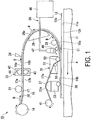
- FIG. 1 is a diagram schematically illustrating an outline configuration of a device for automatically layering prepreg sheets according to a first embodiment of the present invention.
- FIG. 1 schematically illustrates a state in which a semi-cured prepreg sheet 18 forming a layered sheet 16 is layered on a top surface 12a of a layered body 12 put on a stage 11.
- a in FIG. 1 indicates the movement direction (referred to below as the "A direction") of the stage 11 during execution of a prepreg sheet layering process illustrated in FIG. 1 .
- B in FIG. 1 indicates the feeding direction (referred to below as the “feeding direction B") of the layered sheet 16.
- C1 indicates a first region (referred to below as “first region C1") cooled by a cooling unit 29 in the predetermined region.
- first region C1 indicates a region located between a first roller 52 and a second guide roller 28.
- the arrows illustrated below a nozzle 48 in FIG. 1 illustrate how the cooling unit 29 cools a release sheet 17.
- the device for automatically layering prepreg sheets 10 of the first embodiment includes the stage 11, a layered sheet winding roller 14, a first guide roller 21, a layered sheet feeding unit 23, a cutter 24, a first guide member 26, the second guide roller 28, the cooling unit 29 which is a temperature gradient formation unit, a compactor 31, a support member 33, a pressing roller 36, a second guide member 37, and a release sheet recovery roller 41.
- the stage 11 is disposed on a base (not illustrated).
- the stage 11 is capable of moving in the A direction and the opposite direction to the A direction.
- the stage 11 is a flat surface and has a layered body putting surface 11a on which the layered body 12 is put.
- the layered body 12 is a layered body in which one or more semi-cured prepreg sheets are layered.
- the layered body 12 has the top surface 12a to which the semi-cured prepreg sheet 18 forming the layered sheet 16 is attached.
- the layered body 12 is put on the stage 11 such that a bottom surface 12b of the layered body 12 comes into contact with the layered body putting surface 11a.
- a layered sheet winding roller 14 is arranged upstream from the first guide roller 21.
- the layered sheet 16 is wound onto the layered sheet winding roller 14.
- the layered sheet 16 includes the release sheet 17 and the semi-cured prepreg sheet 18.
- the release sheet 17 has one surface 17a to which the semi-cured prepreg sheet 18 is attached, and the other surface 17b which is on the opposite side to the one surface 17a and is pressed by the first roller 52 to be described below.
- release paper can be used as the release sheet 17.
- the prepreg sheet 18 has one surface 18a which faces the top surface 12a of the layered body 12, and the other surface 18b which is on the opposite side to the one surface 18a and is attached to the one surface 17a of the release sheet 17.
- the prepreg sheet 18 includes a fiber sheet (not illustrated) and a semi-cured resin with which the fiber sheet is impregnated.
- a fiber sheet not illustrated
- a semi-cured resin with which the fiber sheet is impregnated for example, glass cloth, carbon fiber, or the like can be used as the fiber sheet.
- the resin forming the prepreg sheet 18 for example, it is possible to use a heat-curable resin, an ultraviolet-curable resin, or the like in a semi-cured state.
- a heat-curable resin it is possible to use, for example, acrylic resins, urea resins, melamine resins, phenol resins, epoxy resins, unsaturated polyesters, alkyd resins, urethane resins, ebonite, or the like.
- the first guide roller 21 is arranged between the layered sheet winding roller 14 and the layered sheet feeding unit 23.
- the roller surface of the first guide roller 21 comes into contact with the one surface 18a of the prepreg sheet 18.
- the first guide roller 21 is a roller for guiding the layered sheet 16 drawn out from the layered sheet winding roller 14 between a first feeding roller 43 and a second feeding roller 44 to be described below.
- the layered sheet feeding unit 23 is arranged between the first guide roller 21 and the cutter 24.
- the layered sheet feeding unit 23 includes a feeding unit main body 42, the first feeding roller 43, and the second feeding roller 44.
- the feeding unit main body 42 incorporates a rotary driving unit which independently rotates the first and second feeding rollers 43 and 44.
- the feeding unit main body 42 rotatably supports the first and second feeding rollers 43 and 44.
- the first feeding roller 43 is arranged directly below the layered sheet 16. The roller surface of the first feeding roller 43 comes into contact with the other surface 17b of the release sheet 17 forming the layered sheet 16.
- the second feeding roller 44 is arranged directly above the layered sheet 16.
- the roller surface of the second feeding roller 44 comes into contact with the one surface 18a of the prepreg sheet 18 forming the layered sheet 16.
- the layered sheet 16 drawn out from the layered sheet winding roller 14 is interposed between the first and second feeding rollers 43 and 44.
- the layered sheet 16 is fed in the B direction by the first and second feeding rollers 43 and 44 rotating in the direction illustrated by the arrows in FIG. 1 .
- the fed layered sheet 16 reaches a guide surface 26a of the first guide member 26.
- the cutter 24 is arranged so as to be able to cut the layered sheet 16 located between the layered sheet feeding unit 23 and the first guide member 26.
- the cutter 24 cuts the layered sheet 16 to be inserted to a desired length.
- the first guide member 26 is arranged downstream from the cutter 24.
- the first guide member 26 has the curved guide surface 26a.
- the first guide member 26 brings the other surface 17b of the release sheet 17 forming the layered sheet 16 fed by the layered sheet feeding unit 23 into contact with the guide surface 26a and reverses the top and bottom surfaces of the layered sheet 16 by guiding the layered sheet 16 along the curved guide surface 26a.
- the one surface 18a of the prepreg sheet 18 facing upward is made to face downward after passing through the first guide member 26. For this reason, the one surface 18a of the prepreg sheet 18 and the top surface 12a of the layered body 12 face each other.
- the second guide roller 28 is arranged between the nozzle 48 forming the cooling unit 29 and the first guide member 26.
- the second guide roller 28 has a roller surface coming into contact with the other surface 17b of the release sheet 17 forming the layered sheet 16.
- the second guide roller 28 guides the layered sheet 16 such that the one surface 18a of the prepreg sheet 18 forming the layered sheet 16 approaches the top surface 12a of the layered body 12.
- the cooling unit 29 has a cooler 46, a pipe 47, and the nozzle 48.
- the cooler 46 is a device for generating cold air by cooling air.
- the pipe 47 is a line for transporting cold air by the cooler 46 to the nozzle 48.
- the nozzle 48 is arranged above the release sheet 17 of the layered sheet 16 located in the first region C1.
- the nozzle 48 is arranged to be separated from the release sheet 17.
- the nozzle 48 blows cold air to the release sheet 17 from the other surface 17b side of the release sheet 17 when the prepreg sheet 18 is attached to the top surface 12a of the layered body 12.
- the cooling unit 29 configured as described above is arranged upstream from the first roller 52 which presses and layers the semi-cured prepreg sheet 18 on the top surface 12a of the layered body 12.
- the cooling unit 29 functions as a temperature gradient formation unit forming a temperature gradient (for example, a temperature gradient of approximately 1 to 2°C with respect to a reference temperature) in which the temperature is lowered in a direction from the one surface 18a of the semi-cured prepreg sheet 18 layered on the top surface 12a of the layered body 12 toward the other surface 17b of the release sheet 17, in the first region C1 of the layered sheet 16.
- a temperature gradient for example, a temperature gradient of approximately 1 to 2°C with respect to a reference temperature
- the temperature is lowered in the direction from the one surface 18a of the semi-cured prepreg sheet 18 layered on the top surface 12a of the layered body 12 toward the other surface 17b of the release sheet 17 in the layered sheet 16 located in the first region C1 arranged between the first roller 52 and the second guide roller 28 and upstream from the first roller 52 suppresses the decrease in the temperature on the one surface 18a side of the semi-cured prepreg sheet 18 and makes it possible to decrease the temperature in the vicinity of the interface between the other surface 18b of the semi-cured prepreg sheet 18 and the one surface 17a of the release sheet 17.
- the release sheet 17 can be easily peeled off from the semi-cured prepreg sheet 18.
- forming the above-described temperature gradient in a portion of the layered sheet 16 corresponding to the first region C1 makes it possible to further suppress the misalignment of the layered body 12 due to the poor releasability of the release sheet 17 in comparison with a case where, for example, the temperature gradient is formed in the layered sheet 16 by line contact using a roller.
- the compactor 31 is capable of moving in the vertical direction (the up and down direction).
- the compactor 31 includes a compactor body 51, the first roller 52, and a second roller 53.
- the compactor body 51 rotatably supports the first and second rollers 52 and 53 and incorporates a rotation driving unit (not illustrated) which independently rotates the first and second rollers 52 and 53.
- the first roller 52 is arranged upstream from the installation position of the second roller 53.
- the first roller 52 is arranged so as to protrude downward from the lower end of the compactor body 51. Due to this, as illustrated in FIG. 1 , when the compactor body 51 moves downward, the roller surface of the first roller 52 comes into contact with the other surface 17b of the release sheet 17 and presses the prepreg sheet 18 against the top surface 12a of the layered body 12 via the release sheet 17. At this time, the prepreg sheet 18 is layered on (attached to) the top surface 12a of the layered body 12 by moving the stage 11 in the A direction 12.
- the second roller 53 is arranged downstream from the installation position of the first roller 52.
- the second roller 53 is a roller with a smaller diameter than the first roller 52.
- the second roller 53 is arranged so as to not protrude from the lower end of the compactor body 51 and to allow the release sheet 17 to be guided in a direction in which the release sheet 17 is peeled off from the semi-cured prepreg sheet 18 layered on the top surface 12a of the layered body 12.
- the second roller 53 is a roller for peeling off the release sheet 17 from the semi-cured prepreg sheet 18 layered on the top surface 12a of the layered body 12.
- the support member 33 is arranged downstream from the compactor 31.
- the support member 33 is capable of moving in the up and down direction.
- a rotation driving unit (not illustrated) which rotates the pressing roller 36 is incorporated in the support member 33.
- the pressing roller 36 is provided in the support member 33 so as to protrude from the lower end of the support member 33.
- the pressing roller 36 has a roller surface.
- the roller surface of the pressing roller 36 comes into contact with the other surface 18b of the semi-cured prepreg sheet 18 which has passed the first roller 52 and layered.
- the pressing roller 36 is a roller for pressing the prepreg sheet 18 against the layered body 12.
- the second guide member 37 is provided on the upper end of the support member 33.
- the upper section of the second guide member 37 has a curved shape.
- the upper section of the second guide member 37 has a guide surface 37a which comes into contact with the one surface 17a of the release sheet 17 which has passed the second roller 53 and guides the release sheet 17 to a release sheet recovery roller 41.
- the release sheet recovery roller 41 is arranged downstream from the second guide member 37.
- the release sheet recovery roller 41 is a roller for recovering the release sheet 17 by winding the release sheet 17 which has passed the second guide member 37.
- the device for automatically layering prepreg sheets of the first embodiment includes the cooling unit 29 (a temperature gradient formation unit) which cools the release sheet 17 from the other surface 17b side of the release sheet 17 so as to form a temperature gradient (in which the temperature is lowered in the direction from the one surface 18a of the semi-cured prepreg sheet 18 layered on the top surface 12a of the layered body 12 toward the other surface 17b of the release sheet 17) in the first region C1 of the layered sheet 16 (the predetermined region in the first embodiment) which is located upstream from the first roller 52.
- the cooling unit 29 a temperature gradient formation unit
- the release sheet 17 can be easily peeled off from the semi-cured prepreg sheet 18.
- the productivity of the semi-cured prepreg layered body can be improved since it is possible to suppress the misalignment of the layered body 12 (in other words, of the semi-cured prepreg layered body under manufacturing) due to the poor releasability of the release sheet 17.
- forming the above-described temperature gradient in the layered sheet 16 corresponding to the first region C1 makes it possible to further suppress the misalignment of the layered body 12 due to the poor releasability of the release sheet 17 in comparison with a case where, for example, the temperature gradient is formed in the layered sheet 16 by line contact using a roller.
- the cooling unit 29 is able to form a temperature gradient in which the temperature is lowered in the direction from the one surface 18a of the semi-cured prepreg sheet 18 toward the other surface 17b of the release sheet 17, and the cooling unit 29 is not limited to the configuration illustrated in FIG. 1 .
- the layered body 12 is put on the layered body putting surface 11a of the stage 11. At this time, the layered body 12 is arranged such that the layered body putting surface 11a comes into contact with the bottom surface 12b of the layered body 12.
- the layered sheet 16 wound by the layered sheet winding roller 14 is fed in the B direction by the layered sheet feeding unit 23.
- the fed layered sheet 16 is guided to the guide surface 26a of the first guide member 26 so that the one surface 18a of the prepreg sheet 18 faces the top surface 12a of the layered body 12.
- a temperature gradient is formed in the first region C1 of the layered sheet 16 located upstream from the first roller 52 such that the temperature is lowered in the direction from the one surface 18a of the semi-cured prepreg sheet 18 layered on the top surface 12a of the layered body 12 toward the other surface 17b of the release sheet 17 (a temperature gradient formation step).
- the release sheet 17 located in the first region C1 is cooled by blowing cold air to the release sheet 17 from the other surface 17b side of the release sheet 17, and a temperature gradient is formed in which the temperature is lowered in the direction from the one surface 18a of the semi-cured prepreg sheet 18 layered on the top surface 12a of the layered body 12 toward the other surface 17b of the release sheet 17.
- the layered sheet 16 including the cooled release sheet 17 is fed between the roller surface of the first roller 52 and the top surface 12a of the layered body 12.
- the semi-cured prepreg sheet 18 forming the layered sheet 16 is layered on the top surface 12a of the layered body 12 formed of one or more layers of semi-cured prepreg sheets (layering step).
- the release sheet 17 is peeled off from the semi-cured prepreg sheet 18 layered on the top surface 12a of the layered body 12 using the second roller 53 arranged downstream from the first roller 52 (peeling step).
- a temperature gradient has been formed in which the temperature is lowered in the direction from the one surface 18a of the semi-cured prepreg sheet 18 layered on the top surface 12a of the layered body 12 toward the other surface 17b of the release sheet 17. Due to this, in addition to suppressing a decrease in temperature on the one surface 18a side of the semi-cured prepreg sheet 18, it is possible to decrease the temperature in the vicinity of the interface between the other surface 18b of the semi-cured prepreg sheet 18 and the one surface 17a of the release sheet 17.
- the release sheet 17 can be easily peeled off from the semi-cured prepreg sheet 18.
- the productivity of the semi-cured prepreg layered body can be improved since it is possible to suppress the misalignment of the layered body 12 (in other words, of the semi-cured prepreg layered body under manufacturing) due to difficulty in peeling off the release sheet 17.
- forming the above-described temperature gradient in the layered sheet 16 corresponding to the first region C1 makes it possible to further suppress the misalignment of the layered body 12 due to difficulty in peeling off the release sheet 16 in comparison with a case where, for example, a temperature gradient is formed in the layered sheet 16 by line contact using a roller.
- the layered sheet 16 is cut by the cutter 24 to a desired length (the same length as the layered body 12) and the semi-cured prepreg sheet 18 is layered so as to cover the top surface 12a of the layered body 12.
- a semi-cured prepreg layered body including the layered body 12 and at least one semi-cured prepreg sheet 18 layered on the layered body 12 is manufactured.
- a completely cured prepreg layered body is manufactured by completely curing the prepreg sheets forming the semi-cured prepreg layered body.
- the method for layering prepreg sheets of the first embodiment includes, before the layering step of layering the semi-cured prepreg sheet 18 forming the layered sheet 16 on the top surface 12a of the layered body 12 formed of one or more layers of semi-cured prepreg sheets, a temperature gradient formation step of forming a temperature gradient in which the temperature is lowered in the direction from the one surface 18a of the semi-cured prepreg sheet 18 layered on the top surface 12a of the layered body 12 toward the other surface 17b of the release sheet 17 in the first region C1 of the layered sheet 16 located upstream from the first roller 52.
- the release sheet 17 can be easily peeled off from the semi-cured prepreg sheet 18.
- the productivity of the semi-cured prepreg layered body can be improved since it is possible to suppress the misalignment of the layered body 12 (in other words, of the semi-cured prepreg layered body under manufacturing) due to the poor releasability of the release sheet 17.
- forming the above-described temperature gradient in a portion of the layered sheet 16 corresponding to the first region C1 makes it possible to further suppress the misalignment of the layered body 12 due to the poor releasability of the release sheet 17 in comparison with a case where, for example, the temperature gradient is formed in the layered sheet 16 by line contact using a roller.
- FIG. 2 is a diagram schematically illustrating an outline configuration of a device for automatically layering prepreg sheets according to a second embodiment of the present invention.
- the same reference numerals are used for constituent components which are the same as in the device for automatically layering prepreg sheets 10 of the first embodiment illustrated in FIG. 1 .
- FIG. 2 the arrows illustrated between a first heating unit 61 and the prepreg sheet 18 illustrate how the first heating unit 61 heats the prepreg sheet 18.
- a device for automatically layering prepreg sheets 60 of the second embodiment has the same configuration as the device for automatically layering prepreg sheets 10 of the first embodiment except that, the first heating unit 61 is further included in the device for automatically layering prepreg sheets 10.
- the second region C2 illustrated in FIG. 2 is a part of the predetermined region and illustrates a region (upstream from the first region C1) between the first guide member 26 and the second guide roller 28.
- the predetermined region of the second embodiment is formed of the first and second regions C1 and C2 which are different.
- the first heating unit 61 is arranged so as to face the one surface 18a of the semi-cured prepreg sheet 18 located in the second region.
- the first heating unit 61 is arranged to be separated from the one surface 18a of the prepreg sheet 18.
- the first heating unit 61 heats the semi-cured prepreg sheet 18 indirectly from the one surface 18a side of the semi-cured prepreg sheet 18.
- a heater can be used as the first heating unit 61.
- the device for automatically layering prepreg sheets of the second embodiment includes the first heating unit 61 which heats the semi-cured prepreg sheet 18 from the one surface 18a side of the semi-cured prepreg sheet 18 located in the second region C2 arranged upstream from the first region C1. Due to this, it is possible to form a temperature gradient (for example, a temperature gradient of approximately 1 to 2°C with respect to a reference temperature) in which the temperature is lowered in the direction from the one surface 18a of the semi-cured prepreg sheet 18 toward the other surface 17b of the release sheet 17.
- a temperature gradient for example, a temperature gradient of approximately 1 to 2°C with respect to a reference temperature
- the method for layering prepreg sheets of the second embodiment using the device for automatically layering prepreg sheets 60 configured as described above is the same as the method for layering prepreg sheets of the first embodiment except that, in the temperature gradient formation step, the semi-cured prepreg sheet 18 is heated from the one surface 18a side of the semi-cured prepreg sheet 18 located in the second region C2.
- the first heating unit 61 may be arranged so as to heat the prepreg sheet 18 located on the opposite side to the release sheet 17 cooled by the cooling unit 29 (in other words, so that the first region C1 and the second region C2 match).
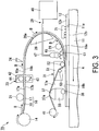
- FIG. 3 is a diagram schematically illustrating an outline configuration of a device for automatically layering prepreg sheets according to a third embodiment of the present invention.
- the same reference numerals are used for constituent components which are the same as in the device for automatically layering prepreg sheets 10 of the first embodiment illustrated in FIG. 1 .
- FIG. 3 the arrows illustrated between a second heating unit 71 and the layered body 12 illustrate how the second heating unit 71 heats the layered body 12.
- the device for automatically layering prepreg sheets 70 of the third embodiment has the same configuration as the device for automatically layering prepreg sheets 10 of the first embodiment except that the second heating unit 71 is further included in the device for automatically layering prepreg sheets 10 of the first embodiment.
- the second heating unit 71 is arranged facing the top surface 12a of the layered body 12 so as to be able to heat the layered body 12 located upstream from the first roller 52.
- the second heating unit 71 is arranged to be separated from the top surface 12a of the layered body 12.
- the second heating unit 71 heats the layered body 12 indirectly from the top surface 12a side of the layered body 12.
- a heater can be used as the second heating unit 71.
- providing the second heating unit 71 which heats the layered body 12 located upstream from the first roller 52 makes it possible to improve the adhesion between the top surface 12a of the layered body 12 and the one surface 18a of the semi-cured prepreg sheet 18.
- the device for automatically layering prepreg sheets 70 of the third embodiment configured as described above can obtain the same effects as the device for automatically layering prepreg sheets 10 of the first embodiment.
- the method for layering prepreg sheets of third embodiment using the device for automatically layering prepreg sheets 70 configured as described above is the same as the method for layering prepreg sheets of the first embodiment except that, in the temperature gradient formation step, the layered body 12 located upstream from the first roller 52 is heated.
- the device for automatically layering prepreg sheets 70 of the third embodiment may include the first heating unit 61 described in the second embodiment.
- the present invention can be applied to a device for automatically layering prepreg sheets and a method for layering prepreg sheets which form a prepreg layered body by layering a plurality of semi-cured prepreg sheets, each of the semi-cured prepreg sheets being formed of a fiber sheet impregnated with resin.
Description
- The present invention relates to a device for automatically layering prepreg sheets and a method for layering prepreg sheets which manufacture prepreg layered bodies formed by layering a plurality of semi-cured prepreg sheets, each of the semi-cured prepreg sheets being formed of a fiber sheet impregnated with resin.
- Conventionally, aircraft fuselages, main wings, and the like are manufactured using completely cured prepreg layered bodies. The completely cured prepreg layered bodies are each formed by layering a plurality of prepreg sheets (FRP sheets), each of the prepreg sheets being formed of a fiber sheet impregnated with resin, to form a semi-cured (incompletely cured) prepreg layered body and then completely curing the semi-cured prepreg layered body.
- The fibers forming the fiber sheet described above extend in the same fiber direction. In addition, the fiber sheet has adhesiveness because an ultraviolet curable resin, a thermosetting resin, or the like in a semi-cured state (incompletely cured state) is used as the resin with which the fiber sheet is impregnated. For this reason, a release sheet is arranged on one surface of the prepreg sheet.
- The prepreg layered body in the semi-cured state described above is formed using a device for automatically layering prepreg sheets. Specifically, the device for automatically layering prepreg sheets forms a semi-cured prepreg layered body by removing the release sheet from the semi-cured prepreg sheet and integrally layering a plurality of the prepreg sheets while the fiber directions of the fiber sheets are made to intersect each other.
- At this time, if air (air pockets) remains between the layered, semi-cured prepreg sheets, the adhesion between the prepreg sheets may decrease.
- In addition, when the above-described semi-cured prepreg layered bodies in which the air remains are completely cured, for example, using heat (in this case, the resin forming the prepreg sheet is a thermosetting resin), the air (the air pockets) expands, which could lead to a further decrease in the adhesion between the prepreg sheets.
- Therefore, conventionally, air (air pockets) is prevented from remaining between layered, semi-cured prepreg sheets by press-bonding the semi-cured prepreg sheets using a compactor (one of the constituent components of the device for automatically layering prepreg sheets) including a piston mechanism.
- However, if the release sheet is insufficiently peeled off from the semi-cured prepreg sheet, the semi-cured prepreg sheets may be pulled by the release sheet such that the prepreg layered body (in other words, a layered body formed of one or more semi-cured prepreg sheets), which is in a semi-cured state under manufacturing floats up, or such that the position of the layered body is shifted from a predetermined position.
- In addition, in a case of using a compactor including a piston mechanism, when there is a layered surface in which the crimping between the semi-cured prepreg sheets is insufficient, there is a possibility that the position of the above-described semi-cured prepreg layered body (layered body) during the manufacturing will be shifted from a predetermined position due to the translational driving force of the compactor.
- Conventionally, in a case where the semi-cured prepreg layered body (layered body) is misaligned under manufacturing, the prepreg layered body (layered body) which has been misaligned under manufacturing is removed manually and the semi-cured prepreg sheet layering process is performed again. For this reason, the productivity of the semi-cured prepreg layered body is decreased.
- For this reason, there is a demand for a technique which, by facilitating the peeling off of the release sheet from the semi-cured prepreg sheet, can suppress the misalignment of the semi-cured prepreg layered body (layered body) under manufacturing and improve the adhesion between the layered, semi-cured prepreg sheets.
-
US-A-2008023130 discloses a device for automatically layering prepreg sheets and a method for layering prepreg sheets. - For example,
JP 2006-281548A -
JP 2006-281548A -
EP 1547753 A1 discloses a method and apparatus for molding the thermosetting composite material and the document specifically teaches to pull out a plurality of strip-prepreg members from respective prepreg rolls and to then layer the strip-prepreg members to form a layered sheet. Then, the so formed layered sheet or body is formed into an L-shape in a hot press unit and it is subsequently cooled in a cooling unit to stop the progression of thermosetting. -
JP 2005-297513 A - With the technique disclosed in
JP 2006-281548A - Due to this, the semi-cured prepreg layered body (layered body) under manufacturing is misaligned with respect to a predetermined position, which may decrease the productivity of the semi-cured prepreg layered body.
- The present invention provides a device with the features of claim 1 for automatically layering prepreg sheets and a method with the features of claim 5 for layering prepreg sheets.
- Claim 1 discloses a first aspect of the present invention.
- According to the aspect described above, the device includes the temperature gradient formation unit which forms a temperature gradient in the predetermined region of the layered sheet located upstream from the first roller such that the temperature is lowered in the direction from the one surface of the semi-cured prepreg sheet layered on the top surface of the layered body toward the other surface of the release sheet. This makes it possible to suppress a temperature decrease on the one surface side of the semi-cured prepreg sheet and to decrease the temperature in the vicinity of the interface between the other surface of the semi-cured prepreg sheet and the one surface of the release sheet.
- This also makes it possible to suppress a decrease in the adhesive force of the one surface of the semi-cured prepreg sheet and to easily peel off the release sheet from the semi-cured prepreg sheet.
- Accordingly, it is possible to suppress the misalignment of the layered body (in other words, of the semi-cured prepreg layered body under manufacturing) due to the poor releasability of the release sheet. Therefore, the productivity of the semi-cured prepreg layered body can be improved.
- In addition, forming the above-described temperature gradient in a portion corresponding to the predetermined region of the layered sheet makes it possible to further suppress the misalignment of the layered body due to the poor releasability of the release sheet in comparison with a case where, for example, the temperature gradient is formed in the layered sheet by line contact using a roller.
- In the device for automatically layering prepreg sheets according to the aspect described above, the predetermined region includes a first region, and the temperature gradient formation unit is a cooling unit which cools the release sheet from the other surface side of the release sheet located in the first region.
- In this manner, the temperature is lowered on the other surface side of the release sheet using a cooling unit, which cools the release sheet from the other surface side of the release sheet located in the first region of the predetermined region, as the temperature gradient formation unit. Therefore, it is possible to form a temperature gradient in which the temperature is lowered in a direction from the one surface of the semi-cured prepreg sheet toward the other surface of the release sheet.
- In the device for automatically layering prepreg sheets according to the aspect described above, the cooling unit may blow cold air to the other surface of the release sheet located in the first region.
- In this manner, in addition to suppressing the generation of condensation on the other surface of the release sheet, providing the cooling unit blowing cold air to the other surface of the release sheet located in the first region makes it possible to form a temperature gradient in which the temperature is lowered in a direction from one surface of the semi-cured prepreg sheet toward the other surface of the release sheet.
- In the device for automatically layering prepreg sheets according to the aspect described above, the predetermined region may include a second region located upstream from the first region, and a first heating unit may be included which heats the semi-cured prepreg sheet from the one surface side of the semi-cured prepreg sheet located in the second region.
- In this manner, providing the first heating unit which heats the semi-cured prepreg sheet from the one surface side of the semi-cured prepreg sheet located in the second region arranged upstream from the first region makes it possible to form a temperature gradient in which the temperature is lowered in a direction from one surface of the semi-cured prepreg sheet toward the other surface of the release sheet.
- Furthermore, providing the cooling unit and the first heating unit that form a temperature gradient in which the temperature is lowered in a direction from one surface of the semi-cured prepreg sheet toward the other surface of the release sheet makes it possible to improve the adhesive force between the top surface of the layered body and one surface of the semi-cured prepreg sheet.
- In the device for automatically layering prepreg sheets according to the aspect described above, a second heating unit which heats the layered body located upstream from the first roller may be included.
- In this manner, providing the second heating unit which heats the layered body located upstream from the first roller makes it possible to improve the adhesive force between the top surface of the layered body and the one surface of the semi-cured prepreg sheet.
- Claim 5 discloses a second aspect of the present invention.
- According to the aspect described above, before the layering step, a temperature gradient is formed in the predetermined region of the layered sheet located upstream from the first roller such that the temperature is lowered in the direction from the one surface of the semi-cured prepreg sheet layered on the top surface of the layered body toward the other surface of the release sheet. This makes it possible to suppress a temperature decrease on the one surface side of the semi-cured prepreg sheet and to decrease the temperature in the vicinity of the interface between the other surface of the semi-cured prepreg sheet and the one surface of the release sheet.
- This also makes it possible to suppress a decrease in the adhesive force of the one surface of the semi-cured prepreg sheet and to easily peel off the release sheet from the semi-cured prepreg sheet.
- Accordingly, the productivity of the semi-cured prepreg layered body can be improved since it is possible to suppress the misalignment of the layered body (in other words, of the semi-cured prepreg layered body under manufacturing) due to the poor releasability of the release sheet.
- In addition, forming the above-described temperature gradient in a portion corresponding to the predetermined region of the layered sheet makes it possible to further suppress the misalignment of the layered body due to the poor releasability of the release sheet in comparison with a case where, for example, the temperature gradient is formed in the layered sheet by line contact using a roller.
- In the method for layering prepreg sheets according to the aspect described above, in the temperature gradient formation step, the release sheet located in the first region of the predetermined region is cooled from the other surface side of the release sheet.
- In this manner, in the temperature gradient formation step, since the temperature is lowered on the other surface side of the release sheet by cooling the release sheet located in the first region of the predetermined region from the other surface side of the release sheet, it is possible to form a temperature gradient in which the temperature is lowered in a direction from one surface of the semi-cured prepreg sheet toward the other surface of the release sheet.
- In the method for layering prepreg sheets according to the aspect described above, in the temperature gradient formation step, cold air may be blown to the other surface of the release sheet located in the first region.
- In this manner, in the temperature gradient formation step, in addition to suppressing the generation of condensation on the other surface of the release sheet, blowing cold air to the other surface of the release sheet located in the first region makes it possible to form a temperature gradient in which the temperature is lowered in a direction from one surface of the semi-cured prepreg sheet toward the other surface of the release sheet.
- In the method for layering prepreg sheets according to the aspect described above, in the temperature gradient formation step, the semi-cured prepreg sheet located in a second region arranged upstream from the first region of the predetermined region is heated from the one surface side of the semi-cured prepreg sheet.
- In this manner, in the temperature gradient formation step, heating the semi-cured prepreg sheet located in the second region arranged upstream from the first region of the predetermined region from the one surface side of the semi-cured prepreg sheet makes it possible to form a temperature gradient in which the temperature is lowered in a direction from one surface of the semi-cured prepreg sheet toward the other surface of the release sheet.
- In the method for layering prepreg sheets according to the aspect described above, in the temperature gradient formation step, the layered body located upstream from the first roller may be heated.
- In this manner, in the temperature gradient formation step, heating the layered body located upstream from the first roller makes it possible to improve the adhesive force between the top surface of the layered body and the one surface of the semi-cured prepreg sheet.
- According to the device for automatically layering prepreg sheets and the method for layering prepreg sheets described above, suppressing the misalignment of the semi-cured prepreg layered body (layered body) under manufacturing makes it possible to improve the productivity of the semi-cured prepreg layered body.
-
-
FIG. 1 is a diagram schematically illustrating an outline configuration of a device for automatically layering prepreg sheets according to a first embodiment of the present invention. -
FIG. 2 is a diagram schematically illustrating an outline configuration of a device for automatically layering prepreg sheets according to a second embodiment of the present invention. -
FIG. 3 is a diagram schematically illustrating an outline configuration of a device for automatically layering prepreg sheets according to a third embodiment of the present invention. - The following describes in detail embodiments of the present invention, with reference to the drawings. Here, the drawings used in the following description are for illustrating the configuration of the embodiments of the present invention and, in terms of the size, thickness, dimensions, and the like of each illustrated part, the actual dimensional relationships in the device for automatically layering prepreg sheets may be different.
-
FIG. 1 is a diagram schematically illustrating an outline configuration of a device for automatically layering prepreg sheets according to a first embodiment of the present invention.FIG. 1 schematically illustrates a state in which asemi-cured prepreg sheet 18 forming alayered sheet 16 is layered on atop surface 12a of alayered body 12 put on astage 11. - A in
FIG. 1 indicates the movement direction (referred to below as the "A direction") of thestage 11 during execution of a prepreg sheet layering process illustrated inFIG. 1 . B inFIG. 1 indicates the feeding direction (referred to below as the "feeding direction B") of thelayered sheet 16. C1 indicates a first region (referred to below as "first region C1") cooled by a coolingunit 29 in the predetermined region. - In addition, the first region C1 indicates a region located between a
first roller 52 and asecond guide roller 28. - The arrows illustrated below a
nozzle 48 inFIG. 1 illustrate how the coolingunit 29 cools arelease sheet 17. - Referring to
FIG. 1 , the device for automatically layeringprepreg sheets 10 of the first embodiment includes thestage 11, a layeredsheet winding roller 14, afirst guide roller 21, a layeredsheet feeding unit 23, acutter 24, afirst guide member 26, thesecond guide roller 28, the coolingunit 29 which is a temperature gradient formation unit, acompactor 31, asupport member 33, apressing roller 36, asecond guide member 37, and a releasesheet recovery roller 41. - The
stage 11 is disposed on a base (not illustrated). Thestage 11 is capable of moving in the A direction and the opposite direction to the A direction. - The
stage 11 is a flat surface and has a layeredbody putting surface 11a on which thelayered body 12 is put. - The
layered body 12 is a layered body in which one or more semi-cured prepreg sheets are layered. Thelayered body 12 has thetop surface 12a to which thesemi-cured prepreg sheet 18 forming thelayered sheet 16 is attached. - The
layered body 12 is put on thestage 11 such that abottom surface 12b of thelayered body 12 comes into contact with the layeredbody putting surface 11a. - A layered
sheet winding roller 14 is arranged upstream from thefirst guide roller 21. Thelayered sheet 16 is wound onto the layeredsheet winding roller 14. - Here, description will be given of the configuration of the
layered sheet 16. Thelayered sheet 16 includes therelease sheet 17 and thesemi-cured prepreg sheet 18. Therelease sheet 17 has onesurface 17a to which thesemi-cured prepreg sheet 18 is attached, and theother surface 17b which is on the opposite side to the onesurface 17a and is pressed by thefirst roller 52 to be described below. For example, release paper can be used as therelease sheet 17. - The
prepreg sheet 18 has onesurface 18a which faces thetop surface 12a of thelayered body 12, and theother surface 18b which is on the opposite side to the onesurface 18a and is attached to the onesurface 17a of therelease sheet 17. - The
prepreg sheet 18 includes a fiber sheet (not illustrated) and a semi-cured resin with which the fiber sheet is impregnated. For example, glass cloth, carbon fiber, or the like can be used as the fiber sheet. - As the resin forming the
prepreg sheet 18, for example, it is possible to use a heat-curable resin, an ultraviolet-curable resin, or the like in a semi-cured state. As the heat-curable resin, it is possible to use, for example, acrylic resins, urea resins, melamine resins, phenol resins, epoxy resins, unsaturated polyesters, alkyd resins, urethane resins, ebonite, or the like. - The
first guide roller 21 is arranged between the layeredsheet winding roller 14 and the layeredsheet feeding unit 23. The roller surface of thefirst guide roller 21 comes into contact with the onesurface 18a of theprepreg sheet 18. Thefirst guide roller 21 is a roller for guiding thelayered sheet 16 drawn out from the layeredsheet winding roller 14 between afirst feeding roller 43 and asecond feeding roller 44 to be described below. - The layered
sheet feeding unit 23 is arranged between thefirst guide roller 21 and thecutter 24. The layeredsheet feeding unit 23 includes a feeding unitmain body 42, thefirst feeding roller 43, and thesecond feeding roller 44. - The feeding unit
main body 42 incorporates a rotary driving unit which independently rotates the first andsecond feeding rollers main body 42 rotatably supports the first andsecond feeding rollers - The
first feeding roller 43 is arranged directly below thelayered sheet 16. The roller surface of thefirst feeding roller 43 comes into contact with theother surface 17b of therelease sheet 17 forming thelayered sheet 16. - The
second feeding roller 44 is arranged directly above thelayered sheet 16. The roller surface of thesecond feeding roller 44 comes into contact with the onesurface 18a of theprepreg sheet 18 forming thelayered sheet 16. - The
layered sheet 16 drawn out from the layeredsheet winding roller 14 is interposed between the first andsecond feeding rollers layered sheet 16 is fed in the B direction by the first andsecond feeding rollers FIG. 1 . After that, the fedlayered sheet 16 reaches aguide surface 26a of thefirst guide member 26. - The
cutter 24 is arranged so as to be able to cut thelayered sheet 16 located between the layeredsheet feeding unit 23 and thefirst guide member 26. Thecutter 24 cuts the layeredsheet 16 to be inserted to a desired length. - The
first guide member 26 is arranged downstream from thecutter 24. Thefirst guide member 26 has thecurved guide surface 26a. Thefirst guide member 26 brings theother surface 17b of therelease sheet 17 forming thelayered sheet 16 fed by the layeredsheet feeding unit 23 into contact with theguide surface 26a and reverses the top and bottom surfaces of thelayered sheet 16 by guiding thelayered sheet 16 along thecurved guide surface 26a. - Due to this, in the feeding step carried out by the layered
sheet feeding unit 23, the onesurface 18a of theprepreg sheet 18 facing upward is made to face downward after passing through thefirst guide member 26. For this reason, the onesurface 18a of theprepreg sheet 18 and thetop surface 12a of thelayered body 12 face each other. - The
second guide roller 28 is arranged between thenozzle 48 forming the coolingunit 29 and thefirst guide member 26. Thesecond guide roller 28 has a roller surface coming into contact with theother surface 17b of therelease sheet 17 forming thelayered sheet 16. - By coming into contact with the
other surface 17b of therelease sheet 17 forming thelayered sheet 16, thesecond guide roller 28 guides thelayered sheet 16 such that the onesurface 18a of theprepreg sheet 18 forming thelayered sheet 16 approaches thetop surface 12a of thelayered body 12. - The cooling
unit 29 has a cooler 46, apipe 47, and thenozzle 48. The cooler 46 is a device for generating cold air by cooling air. - One end of the
pipe 47 is connected with the cooler 46 and the other end is connected with thenozzle 48. Thepipe 47 is a line for transporting cold air by the cooler 46 to thenozzle 48. - The
nozzle 48 is arranged above therelease sheet 17 of thelayered sheet 16 located in the first region C1. Thenozzle 48 is arranged to be separated from therelease sheet 17. - The
nozzle 48 blows cold air to therelease sheet 17 from theother surface 17b side of therelease sheet 17 when theprepreg sheet 18 is attached to thetop surface 12a of thelayered body 12. - The cooling
unit 29 configured as described above is arranged upstream from thefirst roller 52 which presses and layers thesemi-cured prepreg sheet 18 on thetop surface 12a of thelayered body 12. The coolingunit 29 functions as a temperature gradient formation unit forming a temperature gradient (for example, a temperature gradient of approximately 1 to 2°C with respect to a reference temperature) in which the temperature is lowered in a direction from the onesurface 18a of thesemi-cured prepreg sheet 18 layered on thetop surface 12a of thelayered body 12 toward theother surface 17b of therelease sheet 17, in the first region C1 of thelayered sheet 16. - In this manner, providing the
cooling unit 29 which cools therelease sheet 17 from theother surface 17b side of therelease sheet 17 so as to form a temperature gradient (for example, a temperature gradient of approximately 1 to 2°C with respect to a reference temperature) in which the temperature is lowered in the direction from the onesurface 18a of thesemi-cured prepreg sheet 18 layered on thetop surface 12a of thelayered body 12 toward theother surface 17b of therelease sheet 17 in thelayered sheet 16 located in the first region C1 arranged between thefirst roller 52 and thesecond guide roller 28 and upstream from thefirst roller 52 suppresses the decrease in the temperature on the onesurface 18a side of thesemi-cured prepreg sheet 18 and makes it possible to decrease the temperature in the vicinity of the interface between theother surface 18b of thesemi-cured prepreg sheet 18 and the onesurface 17a of therelease sheet 17. - Due to this, in addition to suppressing a decrease in the adhesive force of the one
surface 18a of thesemi-cured prepreg sheet 18, therelease sheet 17 can be easily peeled off from thesemi-cured prepreg sheet 18. - Accordingly, it is possible to suppress the misalignment of the layered body 12 (in other words, of the semi-cured prepreg layered body under manufacturing) due to the poor releasability of the
release sheet 17. This makes it possible to improve the productivity of the semi-cured prepreg layered body. - In addition, forming the above-described temperature gradient in a portion of the
layered sheet 16 corresponding to the first region C1 makes it possible to further suppress the misalignment of thelayered body 12 due to the poor releasability of therelease sheet 17 in comparison with a case where, for example, the temperature gradient is formed in thelayered sheet 16 by line contact using a roller. - The
compactor 31 is capable of moving in the vertical direction (the up and down direction). Thecompactor 31 includes acompactor body 51, thefirst roller 52, and asecond roller 53. - The
compactor body 51 rotatably supports the first andsecond rollers second rollers - The
first roller 52 is arranged upstream from the installation position of thesecond roller 53. Thefirst roller 52 is arranged so as to protrude downward from the lower end of thecompactor body 51. Due to this, as illustrated inFIG. 1 , when thecompactor body 51 moves downward, the roller surface of thefirst roller 52 comes into contact with theother surface 17b of therelease sheet 17 and presses theprepreg sheet 18 against thetop surface 12a of thelayered body 12 via therelease sheet 17. At this time, theprepreg sheet 18 is layered on (attached to) thetop surface 12a of thelayered body 12 by moving thestage 11 in theA direction 12. - The
second roller 53 is arranged downstream from the installation position of thefirst roller 52. Thesecond roller 53 is a roller with a smaller diameter than thefirst roller 52. - The
second roller 53 is arranged so as to not protrude from the lower end of thecompactor body 51 and to allow therelease sheet 17 to be guided in a direction in which therelease sheet 17 is peeled off from thesemi-cured prepreg sheet 18 layered on thetop surface 12a of thelayered body 12. - The
second roller 53 is a roller for peeling off therelease sheet 17 from thesemi-cured prepreg sheet 18 layered on thetop surface 12a of thelayered body 12. - The
support member 33 is arranged downstream from thecompactor 31. Thesupport member 33 is capable of moving in the up and down direction. A rotation driving unit (not illustrated) which rotates thepressing roller 36 is incorporated in thesupport member 33. - The
pressing roller 36 is provided in thesupport member 33 so as to protrude from the lower end of thesupport member 33. Thepressing roller 36 has a roller surface. The roller surface of thepressing roller 36 comes into contact with theother surface 18b of thesemi-cured prepreg sheet 18 which has passed thefirst roller 52 and layered. Thepressing roller 36 is a roller for pressing theprepreg sheet 18 against thelayered body 12. - The
second guide member 37 is provided on the upper end of thesupport member 33. The upper section of thesecond guide member 37 has a curved shape. The upper section of thesecond guide member 37 has aguide surface 37a which comes into contact with the onesurface 17a of therelease sheet 17 which has passed thesecond roller 53 and guides therelease sheet 17 to a releasesheet recovery roller 41. - The release
sheet recovery roller 41 is arranged downstream from thesecond guide member 37. The releasesheet recovery roller 41 is a roller for recovering therelease sheet 17 by winding therelease sheet 17 which has passed thesecond guide member 37. - The device for automatically layering prepreg sheets of the first embodiment includes the cooling unit 29 (a temperature gradient formation unit) which cools the
release sheet 17 from theother surface 17b side of therelease sheet 17 so as to form a temperature gradient (in which the temperature is lowered in the direction from the onesurface 18a of thesemi-cured prepreg sheet 18 layered on thetop surface 12a of thelayered body 12 toward theother surface 17b of the release sheet 17) in the first region C1 of the layered sheet 16 (the predetermined region in the first embodiment) which is located upstream from thefirst roller 52. Due to this, in addition to suppressing a decrease in temperature on the onesurface 18a side of thesemi-cured prepreg sheet 18, it is possible to decrease the temperature in the vicinity of the interface between theother surface 18b of thesemi-cured prepreg sheet 18 and the onesurface 17a of therelease sheet 17. - Due to this, in addition to suppressing a decrease in the adhesive force of the one
surface 18a of thesemi-cured prepreg sheet 18, therelease sheet 17 can be easily peeled off from thesemi-cured prepreg sheet 18. - Accordingly, the productivity of the semi-cured prepreg layered body can be improved since it is possible to suppress the misalignment of the layered body 12 (in other words, of the semi-cured prepreg layered body under manufacturing) due to the poor releasability of the
release sheet 17. - In addition, forming the above-described temperature gradient in the
layered sheet 16 corresponding to the first region C1 makes it possible to further suppress the misalignment of thelayered body 12 due to the poor releasability of therelease sheet 17 in comparison with a case where, for example, the temperature gradient is formed in thelayered sheet 16 by line contact using a roller. - Here, in the first embodiment, as an example of the cooling
unit 29, description has been given of a case where the first region C1 is cooled using cold air; however, it is sufficient if the coolingunit 29 is able to form a temperature gradient in which the temperature is lowered in the direction from the onesurface 18a of thesemi-cured prepreg sheet 18 toward theother surface 17b of therelease sheet 17, and thecooling unit 29 is not limited to the configuration illustrated inFIG. 1 . - Next, with reference to
FIG. 1 , description will be given of a method for layering prepreg sheets using the device for automatically layeringprepreg sheets 10 of the first embodiment. - Firstly, the
layered body 12 is put on the layeredbody putting surface 11a of thestage 11. At this time, thelayered body 12 is arranged such that the layeredbody putting surface 11a comes into contact with thebottom surface 12b of thelayered body 12. - Next, the
layered sheet 16 wound by the layeredsheet winding roller 14 is fed in the B direction by the layeredsheet feeding unit 23. The fedlayered sheet 16 is guided to theguide surface 26a of thefirst guide member 26 so that the onesurface 18a of theprepreg sheet 18 faces thetop surface 12a of thelayered body 12. - Next, a temperature gradient is formed in the first region C1 of the
layered sheet 16 located upstream from thefirst roller 52 such that the temperature is lowered in the direction from the onesurface 18a of thesemi-cured prepreg sheet 18 layered on thetop surface 12a of thelayered body 12 toward theother surface 17b of the release sheet 17 (a temperature gradient formation step). - Specifically, the
release sheet 17 located in the first region C1 is cooled by blowing cold air to therelease sheet 17 from theother surface 17b side of therelease sheet 17, and a temperature gradient is formed in which the temperature is lowered in the direction from the onesurface 18a of thesemi-cured prepreg sheet 18 layered on thetop surface 12a of thelayered body 12 toward theother surface 17b of therelease sheet 17. - After that, the
layered sheet 16 including the cooledrelease sheet 17 is fed between the roller surface of thefirst roller 52 and thetop surface 12a of thelayered body 12. - Next, by pressing the
other surface 17b of therelease sheet 17 of thelayered sheet 16 using thefirst roller 52, thesemi-cured prepreg sheet 18 forming thelayered sheet 16 is layered on thetop surface 12a of thelayered body 12 formed of one or more layers of semi-cured prepreg sheets (layering step). - Next, the
release sheet 17 is peeled off from thesemi-cured prepreg sheet 18 layered on thetop surface 12a of thelayered body 12 using thesecond roller 53 arranged downstream from the first roller 52 (peeling step). - At this time, as described above, in a portion of the
layered sheet 16 layered by thefirst roller 52, a temperature gradient has been formed in which the temperature is lowered in the direction from the onesurface 18a of thesemi-cured prepreg sheet 18 layered on thetop surface 12a of thelayered body 12 toward theother surface 17b of therelease sheet 17. Due to this, in addition to suppressing a decrease in temperature on the onesurface 18a side of thesemi-cured prepreg sheet 18, it is possible to decrease the temperature in the vicinity of the interface between theother surface 18b of thesemi-cured prepreg sheet 18 and the onesurface 17a of therelease sheet 17. - Due to this, in addition to suppressing a decrease in the adhesive force of the one
surface 18a of thesemi-cured prepreg sheet 18, therelease sheet 17 can be easily peeled off from thesemi-cured prepreg sheet 18. - Accordingly, the productivity of the semi-cured prepreg layered body can be improved since it is possible to suppress the misalignment of the layered body 12 (in other words, of the semi-cured prepreg layered body under manufacturing) due to difficulty in peeling off the
release sheet 17. - In addition, forming the above-described temperature gradient in the
layered sheet 16 corresponding to the first region C1 makes it possible to further suppress the misalignment of thelayered body 12 due to difficulty in peeling off therelease sheet 16 in comparison with a case where, for example, a temperature gradient is formed in thelayered sheet 16 by line contact using a roller. - After that, the
layered sheet 16 is cut by thecutter 24 to a desired length (the same length as the layered body 12) and thesemi-cured prepreg sheet 18 is layered so as to cover thetop surface 12a of thelayered body 12. - By repeating the above-described steps, a semi-cured prepreg layered body including the layered
body 12 and at least onesemi-cured prepreg sheet 18 layered on thelayered body 12 is manufactured. - After that, a completely cured prepreg layered body is manufactured by completely curing the prepreg sheets forming the semi-cured prepreg layered body.
- The method for layering prepreg sheets of the first embodiment includes, before the layering step of layering the
semi-cured prepreg sheet 18 forming thelayered sheet 16 on thetop surface 12a of thelayered body 12 formed of one or more layers of semi-cured prepreg sheets, a temperature gradient formation step of forming a temperature gradient in which the temperature is lowered in the direction from the onesurface 18a of thesemi-cured prepreg sheet 18 layered on thetop surface 12a of thelayered body 12 toward theother surface 17b of therelease sheet 17 in the first region C1 of thelayered sheet 16 located upstream from thefirst roller 52. Due to this, in addition to suppressing a decrease in temperature on the onesurface 18a side of thesemi-cured prepreg sheet 18, it is possible to decrease the temperature in the vicinity of the interface between theother surface 18b of thesemi-cured prepreg sheet 18 and the onesurface 17a of therelease sheet 17. - Due to this, in addition to suppressing a decrease in the adhesive force of the one
surface 18a of thesemi-cured prepreg sheet 18, therelease sheet 17 can be easily peeled off from thesemi-cured prepreg sheet 18. - Accordingly, the productivity of the semi-cured prepreg layered body can be improved since it is possible to suppress the misalignment of the layered body 12 (in other words, of the semi-cured prepreg layered body under manufacturing) due to the poor releasability of the
release sheet 17. - In addition, forming the above-described temperature gradient in a portion of the
layered sheet 16 corresponding to the first region C1 makes it possible to further suppress the misalignment of thelayered body 12 due to the poor releasability of therelease sheet 17 in comparison with a case where, for example, the temperature gradient is formed in thelayered sheet 16 by line contact using a roller. -
FIG. 2 is a diagram schematically illustrating an outline configuration of a device for automatically layering prepreg sheets according to a second embodiment of the present invention. InFIG. 2 , the same reference numerals are used for constituent components which are the same as in the device for automatically layeringprepreg sheets 10 of the first embodiment illustrated inFIG. 1 . - In
FIG. 2 , the arrows illustrated between afirst heating unit 61 and theprepreg sheet 18 illustrate how thefirst heating unit 61 heats theprepreg sheet 18. - With reference to
FIG. 2 , a device for automatically layeringprepreg sheets 60 of the second embodiment has the same configuration as the device for automatically layeringprepreg sheets 10 of the first embodiment except that, thefirst heating unit 61 is further included in the device for automatically layeringprepreg sheets 10. - The second region C2 illustrated in
FIG. 2 is a part of the predetermined region and illustrates a region (upstream from the first region C1) between thefirst guide member 26 and thesecond guide roller 28. - That is, the predetermined region of the second embodiment is formed of the first and second regions C1 and C2 which are different.
- The
first heating unit 61 is arranged so as to face the onesurface 18a of thesemi-cured prepreg sheet 18 located in the second region. Thefirst heating unit 61 is arranged to be separated from the onesurface 18a of theprepreg sheet 18. - Due to this, the
first heating unit 61 heats thesemi-cured prepreg sheet 18 indirectly from the onesurface 18a side of thesemi-cured prepreg sheet 18. For example, a heater can be used as thefirst heating unit 61. - The device for automatically layering prepreg sheets of the second embodiment includes the
first heating unit 61 which heats thesemi-cured prepreg sheet 18 from the onesurface 18a side of thesemi-cured prepreg sheet 18 located in the second region C2 arranged upstream from the first region C1. Due to this, it is possible to form a temperature gradient (for example, a temperature gradient of approximately 1 to 2°C with respect to a reference temperature) in which the temperature is lowered in the direction from the onesurface 18a of thesemi-cured prepreg sheet 18 toward theother surface 17b of therelease sheet 17. - In addition, in addition to forming the temperature gradient in which the temperature is lowered in a direction from the one
surface 18a of thesemi-cured prepreg sheet 18 toward theother surface 17b of therelease sheet 17, having the coolingunit 29 and thefirst heating unit 61 makes it possible to improve the adhesion between thetop surface 12a of thelayered body 12 and the onesurface 18a of thesemi-cured prepreg sheet 18. - The method for layering prepreg sheets of the second embodiment using the device for automatically layering
prepreg sheets 60 configured as described above is the same as the method for layering prepreg sheets of the first embodiment except that, in the temperature gradient formation step, thesemi-cured prepreg sheet 18 is heated from the onesurface 18a side of thesemi-cured prepreg sheet 18 located in the second region C2. - Here, in the second embodiment, description has been given of a case where the first region C1 and the second region C2 are different as an example; however, the
first heating unit 61 may be arranged so as to heat theprepreg sheet 18 located on the opposite side to therelease sheet 17 cooled by the cooling unit 29 (in other words, so that the first region C1 and the second region C2 match). - Even in this case, it is possible to obtain the same effects as the device for automatically layering
prepreg sheets 60 of the second embodiment. -
FIG. 3 is a diagram schematically illustrating an outline configuration of a device for automatically layering prepreg sheets according to a third embodiment of the present invention. InFIG. 3 , the same reference numerals are used for constituent components which are the same as in the device for automatically layeringprepreg sheets 10 of the first embodiment illustrated inFIG. 1 . - In
FIG. 3 , the arrows illustrated between asecond heating unit 71 and thelayered body 12 illustrate how thesecond heating unit 71 heats thelayered body 12. - With reference to
FIG. 3 , the device for automatically layeringprepreg sheets 70 of the third embodiment has the same configuration as the device for automatically layeringprepreg sheets 10 of the first embodiment except that thesecond heating unit 71 is further included in the device for automatically layeringprepreg sheets 10 of the first embodiment. - The
second heating unit 71 is arranged facing thetop surface 12a of thelayered body 12 so as to be able to heat the layeredbody 12 located upstream from thefirst roller 52. Thesecond heating unit 71 is arranged to be separated from thetop surface 12a of thelayered body 12. - Due to this, the
second heating unit 71 heats thelayered body 12 indirectly from thetop surface 12a side of thelayered body 12. For example, a heater can be used as thesecond heating unit 71. - According to the device for automatically layering prepreg sheets of the third embodiment, providing the
second heating unit 71 which heats thelayered body 12 located upstream from thefirst roller 52 makes it possible to improve the adhesion between thetop surface 12a of thelayered body 12 and the onesurface 18a of thesemi-cured prepreg sheet 18. - In addition, the device for automatically layering
prepreg sheets 70 of the third embodiment configured as described above can obtain the same effects as the device for automatically layeringprepreg sheets 10 of the first embodiment. - The method for layering prepreg sheets of third embodiment using the device for automatically layering
prepreg sheets 70 configured as described above is the same as the method for layering prepreg sheets of the first embodiment except that, in the temperature gradient formation step, thelayered body 12 located upstream from thefirst roller 52 is heated. - Here, the device for automatically layering
prepreg sheets 70 of the third embodiment may include thefirst heating unit 61 described in the second embodiment. - The present invention can be applied to a device for automatically layering prepreg sheets and a method for layering prepreg sheets which form a prepreg layered body by layering a plurality of semi-cured prepreg sheets, each of the semi-cured prepreg sheets being formed of a fiber sheet impregnated with resin.
-
- 10, 60, 70
- Device for automatically layering prepreg sheets
- 11
- Stage
- 11a
- Layered body putting surface
- 12
- Layered body
- 12a
- Top surface
- 12b
- Bottom surface
- 14
- Layered sheet winding roller
- 16
- Layered sheet
- 17
- Release sheet
- 17a, 18a
- One surface
- 17b, 18b
- Other surface
- 18
- Prepreg sheet
- 21
- First guide roller
- 23
- Layered sheet feeding unit
- 24
- Cutter
- 26
- First guide member
- 26a, 37a
- Guide surface
- 28
- Second guide roller
- 29
- Cooling unit
- 31
- Compactor
- 33
- Support member
- 36
- Pressing roller
- 37
- Second guide member
- 41
- Release sheet recovery roller
- 42
- Feeding unit main body
- 43
- First feeding roller
- 44
- Second feeding roller
- 46
- Cooler
- 47
- Pipe
- 48
- Nozzle
- 51
- Compactor body
- 52
- First roller
- 53
- Second roller
- 61
- First heating unit
- 71
- Second heating unit
- A
- Direction
- B
- Feeding direction
- C1
- First region
- C2
- Second region
Claims (8)
- A device (10;60;70) for automatically layering prepreg sheets, the device (10;60;70) arranged to form a prepreg layered body by layering a plurality of semi-cured prepreg sheets (18), each of the semi-cured prepreg sheets (18) being formed of a fiber sheet impregnated with resin, the device (10;60;70) comprising:a first roller (52) which is provided to press a layered sheet (16) including a release sheet (17) and the semi-cured prepreg sheet (18) attached to one surface (17a) of the release sheet (17), from another surface (17b) of the release sheet (17) so as to layer the semi-cured prepreg sheet (18) forming the layered sheet (16) on a top surface (12a) of a layered body (12) formed of one or more layers of semi-cured prepreg sheets (18);a second roller (53) arranged downstream from the first roller (52), the second roller (53) provided for guiding the release sheet (17) in a direction in which the release sheet (17) is peeled off from the semi-cured prepreg sheet (18) layered on the top surface (12a) of the layered body (12); anda temperature gradient formation unit which is provided to form a temperature gradient in a predetermined region of the layered sheet (16) located upstream from the first roller (52) such that the temperature is lowered in a direction from one surface (18a) of the semi-cured prepreg sheet (18) layered on the top surface (12a) of the layered body (12) toward the other surface (17b) of the release sheet (17),wherein the predetermined region includes a first region (C1), andthe temperature gradient formation unit is a cooling unit (29) which is provided to cool the release sheet (17) located in the first region (C1) from the other surface (17b) side of the release sheet (17).
- The device for automatically layering prepreg sheets according to claim 1,
wherein the cooling unit is provided to blow cold air to the other surface of the release sheet located in the first region. - The device (10;60;70) for automatically layering prepreg sheets according to claim 1 or 2, further comprising:a first heating unit (61),wherein the predetermined region includes a second region (C2) located upstream from the first region (C1), and the first heating unit (61) is provided to heat the semi-cured prepreg sheet (18) from the one surface (18a) side of the semi-cured prepreg sheet (18) located in the second region (C2).
- The device (60) for automatically layering prepreg sheets according to any one of claims 1 to 3, further comprising:
a second heating unit (71) which is provided to heat the layered body (12) located upstream from the first roller (52). - A method for layering prepreg sheets in which a prepreg layered body is formed by layering a plurality of semi-cured prepreg sheets (18), each of the semi-cured prepreg sheets (18) being formed of a fiber sheet impregnated with resin, the method comprising:a layering step of pressing a layered sheet (16) including a release sheet (17) and the semi-cured prepreg sheet (18) attached to one surface (17a) of the release sheet (17), from another surface (17b) of the release sheet (17) with a first roller (52) so as to layer the semi-cured prepreg sheet (18) forming the layered sheet (16) on a top surface (12a) of a layered body (12) formed of one or more layers of semi-cured prepreg sheets (18);a peeling-off step of peeling off the release sheet (17) from the semi-cured prepreg sheet (18) layered on the top surface (12a) of the layered body (12) with a second roller (53) arranged downstream from the first roller (52) after the layering step; anda temperature gradient formation step of forming a temperature gradient in a predetermined region of the layered sheet (16) located upstream from the first roller (52) such that the temperature is lowered in a direction from one surface (18a) of the semi-cured prepreg sheet (18) layered on the top surface (12a) of the layered body (12) toward the other surface (17b) of the release sheet (17) before the layering step,wherein, in the temperature gradient formation step, the release sheet (17) located in a first region (C1) of the predetermined region is cooled from the other surface (17b) side of the release sheet (17).
- The method for layering prepreg sheets according to claim 5,
wherein, in the temperature gradient formation step, cold air is blown to the other surface (17b) of the release sheet (17) located in the first region (C1). - The method for layering prepreg sheets according to claim 5 or 6,
wherein, in the temperature gradient formation step, the semi-cured prepreg sheet (18) located in a second region (C2) arranged upstream from the first region (C1) of the predetermined region is heated from the one surface (18a) side of the semi-cured prepreg sheet (18). - The method for layering prepreg sheets according to any one of claims 5 to 7,
wherein, in the temperature gradient formation step, the layered body (12) located upstream from the first roller (52) is heated.
Applications Claiming Priority (2)
| Application Number | Priority Date | Filing Date | Title |
|---|---|---|---|
| JP2013230373A JP6288495B2 (en) | 2013-11-06 | 2013-11-06 | Prepreg sheet automatic laminating apparatus and prepreg sheet laminating method |
| PCT/JP2014/079355 WO2015068734A1 (en) | 2013-11-06 | 2014-11-05 | Device for automatically layering prepreg sheets and method for layering prepreg sheets |
Publications (3)
| Publication Number | Publication Date |
|---|---|
| EP3042754A1 EP3042754A1 (en) | 2016-07-13 |
| EP3042754A4 EP3042754A4 (en) | 2016-11-02 |
| EP3042754B1 true EP3042754B1 (en) | 2020-10-07 |
Family
ID=53041511
Family Applications (1)
| Application Number | Title | Priority Date | Filing Date |
|---|---|---|---|
| EP14860804.5A Active EP3042754B1 (en) | 2013-11-06 | 2014-11-05 | Device for automatically layering prepreg sheets and method for layering prepreg sheets |
Country Status (7)
| Country | Link |
|---|---|
| US (1) | US9993979B2 (en) |
| EP (1) | EP3042754B1 (en) |
| JP (1) | JP6288495B2 (en) |
| CN (1) | CN105612045B (en) |
| BR (1) | BR112016007532A2 (en) |
| CA (1) | CA2926333C (en) |
| WO (1) | WO2015068734A1 (en) |
Families Citing this family (7)
| Publication number | Priority date | Publication date | Assignee | Title |
|---|---|---|---|---|
| GB201511706D0 (en) | 2015-07-03 | 2015-08-19 | Composite Technology & Applic Ltd | A Method Of Manufacturing A Composite Component |
| KR102087409B1 (en) * | 2015-11-11 | 2020-03-11 | 주식회사 엘지화학 | Prepreg, composites and method for manufacturing the same |
| FR3051709B1 (en) | 2016-05-24 | 2019-01-25 | Airbus Helicopters | REMOVAL HEAD OF AN IMPREGNATED FIBER RIBBON, AND DEVICE FOR PLACING SUCH RIBBON |
| TWI645950B (en) * | 2017-12-29 | 2019-01-01 | 宏茂科技股份有限公司 | Method for removing semi-cured resin |
| KR102124532B1 (en) * | 2018-10-02 | 2020-06-18 | 주식회사 무창에프엔지 | Attaching apparatus for film on glass using air |
| JP2020132360A (en) | 2019-02-20 | 2020-08-31 | 三菱重工業株式会社 | Splice apparatus, and composite material automatic lamination device |
| JP2020131623A (en) * | 2019-02-22 | 2020-08-31 | 三菱重工業株式会社 | Composite material automatic lamination device |
Citations (1)
| Publication number | Priority date | Publication date | Assignee | Title |
|---|---|---|---|---|
| US20080023130A1 (en) * | 2006-07-31 | 2008-01-31 | Airbus Espana, S.L. | Tool and process for manufacturing pieces of composite materials outside an autoclave |
Family Cites Families (16)
| Publication number | Priority date | Publication date | Assignee | Title |
|---|---|---|---|---|
| US5201979A (en) * | 1987-05-08 | 1993-04-13 | Research Association For New Technology Development Of High Performance Polymer | Method of manufacturing a sheet-prepreg reinforced with fibers |
| DE4130269C2 (en) * | 1990-09-13 | 1996-05-23 | Toshiba Machine Co Ltd | Method and device for manufacturing laminated prepreg parts |
| JPH05269881A (en) * | 1992-01-29 | 1993-10-19 | Toshiba Mach Co Ltd | Method and apparatus for producing prepreg laminated material |
| JPH10272896A (en) * | 1997-03-28 | 1998-10-13 | Dainippon Printing Co Ltd | Method for transferring curved surface |
| JP4170781B2 (en) * | 2003-01-17 | 2008-10-22 | 松下電器産業株式会社 | Substrate manufacturing method |
| US7282107B2 (en) * | 2003-08-22 | 2007-10-16 | The Boeing Company | Multiple head automated composite laminating machine for the fabrication of large barrel section components |
| JP4218519B2 (en) * | 2003-12-26 | 2009-02-04 | 戸田工業株式会社 | Magnetic field antenna, wireless system and communication system using the same |
| JP2005297513A (en) * | 2004-04-16 | 2005-10-27 | Fuji Heavy Ind Ltd | Automatic laminating machine |
| JP2005329593A (en) * | 2004-05-19 | 2005-12-02 | Fuji Heavy Ind Ltd | Automatic lamination apparatus |
| JP2006281548A (en) | 2005-03-31 | 2006-10-19 | Fuji Heavy Ind Ltd | Method for molding visible light-curable fiber-reinforced resin composite material |
| JP2007030336A (en) * | 2005-07-27 | 2007-02-08 | Mitsubishi Heavy Ind Ltd | Laminating method and apparatus for fiber-reinforced plastic |
| JP2008238809A (en) * | 2007-02-28 | 2008-10-09 | Toray Ind Inc | Method of manufacturing laminate |
| JP5422439B2 (en) * | 2010-02-26 | 2014-02-19 | 三菱重工業株式会社 | Prepreg laminating head and prepreg automatic laminating apparatus provided with the same |
| JP5439225B2 (en) * | 2010-02-26 | 2014-03-12 | 三菱重工業株式会社 | Prepreg laminating head and prepreg automatic laminating apparatus provided with the same |
| US20130059125A1 (en) * | 2011-09-01 | 2013-03-07 | Honda Motor Co., Ltd. | Manufacturing apparatus and manufacturing method of composite structural member |
| CN102776299A (en) * | 2012-07-26 | 2012-11-14 | 张放 | Surface finishing method by using release paper for embossing on surface of straightly-pasted transfer film super fiber leather |
-
2013
- 2013-11-06 JP JP2013230373A patent/JP6288495B2/en active Active
-
2014
- 2014-11-05 EP EP14860804.5A patent/EP3042754B1/en active Active
- 2014-11-05 BR BR112016007532A patent/BR112016007532A2/en not_active IP Right Cessation
- 2014-11-05 CA CA2926333A patent/CA2926333C/en active Active
- 2014-11-05 US US15/026,489 patent/US9993979B2/en active Active
- 2014-11-05 CN CN201480055558.8A patent/CN105612045B/en not_active Expired - Fee Related
- 2014-11-05 WO PCT/JP2014/079355 patent/WO2015068734A1/en active Application Filing
Patent Citations (1)
| Publication number | Priority date | Publication date | Assignee | Title |
|---|---|---|---|---|
| US20080023130A1 (en) * | 2006-07-31 | 2008-01-31 | Airbus Espana, S.L. | Tool and process for manufacturing pieces of composite materials outside an autoclave |
Also Published As
| Publication number | Publication date |
|---|---|
| BR112016007532A2 (en) | 2017-08-01 |
| US20160243769A1 (en) | 2016-08-25 |
| WO2015068734A1 (en) | 2015-05-14 |
| EP3042754A1 (en) | 2016-07-13 |
| CA2926333C (en) | 2018-01-02 |
| JP6288495B2 (en) | 2018-03-07 |
| CN105612045B (en) | 2017-09-29 |
| EP3042754A4 (en) | 2016-11-02 |
| CA2926333A1 (en) | 2015-05-14 |
| CN105612045A (en) | 2016-05-25 |
| US9993979B2 (en) | 2018-06-12 |
| JP2015089647A (en) | 2015-05-11 |
Similar Documents
| Publication | Publication Date | Title |
|---|---|---|
| EP3042754B1 (en) | Device for automatically layering prepreg sheets and method for layering prepreg sheets | |
| JP4952056B2 (en) | Preform manufacturing method and preform manufacturing apparatus | |
| JP4867917B2 (en) | Method and apparatus for producing reinforcing fiber molded body | |
| JP5668874B2 (en) | Preform manufacturing method and fiber reinforced resin molded product manufacturing method | |
| EP2489498B1 (en) | Method and device for manufacturing beam member | |
| EP3862170B1 (en) | Automatic layering method and device for thin tape | |
| JP2008055609A (en) | Uncured continuous preforming method of composite material | |
| JP2008213311A (en) | Method of molding continuously composite material having stepwise cross-section thickness | |
| EP1157811A2 (en) | Continuous forming device of FRP square pipe | |
| WO2013084552A1 (en) | Preform manufacturing method and fiber-reinforced plastic molding manufacturing method | |
| KR20140087010A (en) | Process for producing plastic molded pieces | |
| JP2013248848A (en) | Continuous preforming apparatus of composite material stringer | |
| JP2020082723A (en) | Composite laminate structure having cellular core formed using continuous compression molding process | |
| JP2006289619A (en) | Method and apparatus for manufacturing multi-axial multilayered reinforced sheet | |
| EP3466631B1 (en) | Method and apparatus for manufacturing composite material | |
| JP2011057767A (en) | Method and apparatus for manufacturing preform for fiber-reinforced composite material | |
| JP6935620B2 (en) | Automatic laminating method and equipment for thin-layer prepreg tape | |
| JP6152244B2 (en) | Molding apparatus and manufacturing method | |
| JP2012016939A (en) | Method for producing composite molded article | |
| JP7175820B2 (en) | Prepreg molding method | |
| JPH0818379B2 (en) | Method and apparatus for laminating prepreg | |
| TW200404845A (en) | Paper-free prepreg |
Legal Events
| Date | Code | Title | Description |
|---|---|---|---|
| PUAI | Public reference made under article 153(3) epc to a published international application that has entered the european phase |
Free format text: ORIGINAL CODE: 0009012 |
|
| 17P | Request for examination filed |
Effective date: 20160404 |
|
| AK | Designated contracting states |
Kind code of ref document: A1 Designated state(s): AL AT BE BG CH CY CZ DE DK EE ES FI FR GB GR HR HU IE IS IT LI LT LU LV MC MK MT NL NO PL PT RO RS SE SI SK SM TR |
|
| AX | Request for extension of the european patent |
Extension state: BA ME |
|
| A4 | Supplementary search report drawn up and despatched |
Effective date: 20161004 |
|
| RIC1 | Information provided on ipc code assigned before grant |
Ipc: B29C 43/18 20060101ALI20160927BHEP Ipc: B29C 70/06 20060101AFI20160927BHEP Ipc: B29K 105/08 20060101ALI20160927BHEP |
|
| DAX | Request for extension of the european patent (deleted) | ||
| GRAP | Despatch of communication of intention to grant a patent |
Free format text: ORIGINAL CODE: EPIDOSNIGR1 |
|
| STAA | Information on the status of an ep patent application or granted ep patent |
Free format text: STATUS: GRANT OF PATENT IS INTENDED |
|
| RIC1 | Information provided on ipc code assigned before grant |
Ipc: B29C 43/18 20060101ALI20200504BHEP Ipc: B29K 105/08 20060101ALI20200504BHEP Ipc: B29C 70/06 20060101AFI20200504BHEP Ipc: B29C 70/38 20060101ALI20200504BHEP |
|
| INTG | Intention to grant announced |
Effective date: 20200602 |
|
| GRAS | Grant fee paid |
Free format text: ORIGINAL CODE: EPIDOSNIGR3 |
|
| GRAA | (expected) grant |
Free format text: ORIGINAL CODE: 0009210 |
|
| STAA | Information on the status of an ep patent application or granted ep patent |
Free format text: STATUS: THE PATENT HAS BEEN GRANTED |
|
| AK | Designated contracting states |
Kind code of ref document: B1 Designated state(s): AL AT BE BG CH CY CZ DE DK EE ES FI FR GB GR HR HU IE IS IT LI LT LU LV MC MK MT NL NO PL PT RO RS SE SI SK SM TR |
|
| REG | Reference to a national code |
Ref country code: GB Ref legal event code: FG4D |
|
| REG | Reference to a national code |
Ref country code: AT Ref legal event code: REF Ref document number: 1320690 Country of ref document: AT Kind code of ref document: T Effective date: 20201015 Ref country code: CH Ref legal event code: EP |
|
| REG | Reference to a national code |
Ref country code: IE Ref legal event code: FG4D |
|
| REG | Reference to a national code |
Ref country code: DE Ref legal event code: R096 Ref document number: 602014071094 Country of ref document: DE |
|
| REG | Reference to a national code |
Ref country code: NL Ref legal event code: MP Effective date: 20201007 |
|
| REG | Reference to a national code |
Ref country code: AT Ref legal event code: MK05 Ref document number: 1320690 Country of ref document: AT Kind code of ref document: T Effective date: 20201007 |
|
| PG25 | Lapsed in a contracting state [announced via postgrant information from national office to epo] |
Ref country code: GR Free format text: LAPSE BECAUSE OF FAILURE TO SUBMIT A TRANSLATION OF THE DESCRIPTION OR TO PAY THE FEE WITHIN THE PRESCRIBED TIME-LIMIT Effective date: 20210108 Ref country code: NL Free format text: LAPSE BECAUSE OF FAILURE TO SUBMIT A TRANSLATION OF THE DESCRIPTION OR TO PAY THE FEE WITHIN THE PRESCRIBED TIME-LIMIT Effective date: 20201007 Ref country code: PT Free format text: LAPSE BECAUSE OF FAILURE TO SUBMIT A TRANSLATION OF THE DESCRIPTION OR TO PAY THE FEE WITHIN THE PRESCRIBED TIME-LIMIT Effective date: 20210208 Ref country code: NO Free format text: LAPSE BECAUSE OF FAILURE TO SUBMIT A TRANSLATION OF THE DESCRIPTION OR TO PAY THE FEE WITHIN THE PRESCRIBED TIME-LIMIT Effective date: 20210107 Ref country code: FI Free format text: LAPSE BECAUSE OF FAILURE TO SUBMIT A TRANSLATION OF THE DESCRIPTION OR TO PAY THE FEE WITHIN THE PRESCRIBED TIME-LIMIT Effective date: 20201007 Ref country code: RS Free format text: LAPSE BECAUSE OF FAILURE TO SUBMIT A TRANSLATION OF THE DESCRIPTION OR TO PAY THE FEE WITHIN THE PRESCRIBED TIME-LIMIT Effective date: 20201007 |
|
| REG | Reference to a national code |
Ref country code: LT Ref legal event code: MG4D |
|
| PG25 | Lapsed in a contracting state [announced via postgrant information from national office to epo] |
Ref country code: SE Free format text: LAPSE BECAUSE OF FAILURE TO SUBMIT A TRANSLATION OF THE DESCRIPTION OR TO PAY THE FEE WITHIN THE PRESCRIBED TIME-LIMIT Effective date: 20201007 Ref country code: IS Free format text: LAPSE BECAUSE OF FAILURE TO SUBMIT A TRANSLATION OF THE DESCRIPTION OR TO PAY THE FEE WITHIN THE PRESCRIBED TIME-LIMIT Effective date: 20210207 Ref country code: LV Free format text: LAPSE BECAUSE OF FAILURE TO SUBMIT A TRANSLATION OF THE DESCRIPTION OR TO PAY THE FEE WITHIN THE PRESCRIBED TIME-LIMIT Effective date: 20201007 Ref country code: PL Free format text: LAPSE BECAUSE OF FAILURE TO SUBMIT A TRANSLATION OF THE DESCRIPTION OR TO PAY THE FEE WITHIN THE PRESCRIBED TIME-LIMIT Effective date: 20201007 Ref country code: BG Free format text: LAPSE BECAUSE OF FAILURE TO SUBMIT A TRANSLATION OF THE DESCRIPTION OR TO PAY THE FEE WITHIN THE PRESCRIBED TIME-LIMIT Effective date: 20210107 Ref country code: AT Free format text: LAPSE BECAUSE OF FAILURE TO SUBMIT A TRANSLATION OF THE DESCRIPTION OR TO PAY THE FEE WITHIN THE PRESCRIBED TIME-LIMIT Effective date: 20201007 Ref country code: ES Free format text: LAPSE BECAUSE OF FAILURE TO SUBMIT A TRANSLATION OF THE DESCRIPTION OR TO PAY THE FEE WITHIN THE PRESCRIBED TIME-LIMIT Effective date: 20201007 |
|
| PG25 | Lapsed in a contracting state [announced via postgrant information from national office to epo] |
Ref country code: HR Free format text: LAPSE BECAUSE OF FAILURE TO SUBMIT A TRANSLATION OF THE DESCRIPTION OR TO PAY THE FEE WITHIN THE PRESCRIBED TIME-LIMIT Effective date: 20201007 |
|
| REG | Reference to a national code |
Ref country code: CH Ref legal event code: PL |
|
| REG | Reference to a national code |
Ref country code: DE Ref legal event code: R097 Ref document number: 602014071094 Country of ref document: DE |
|
| PG25 | Lapsed in a contracting state [announced via postgrant information from national office to epo] |
Ref country code: SK Free format text: LAPSE BECAUSE OF FAILURE TO SUBMIT A TRANSLATION OF THE DESCRIPTION OR TO PAY THE FEE WITHIN THE PRESCRIBED TIME-LIMIT Effective date: 20201007 Ref country code: RO Free format text: LAPSE BECAUSE OF FAILURE TO SUBMIT A TRANSLATION OF THE DESCRIPTION OR TO PAY THE FEE WITHIN THE PRESCRIBED TIME-LIMIT Effective date: 20201007 Ref country code: MC Free format text: LAPSE BECAUSE OF FAILURE TO SUBMIT A TRANSLATION OF THE DESCRIPTION OR TO PAY THE FEE WITHIN THE PRESCRIBED TIME-LIMIT Effective date: 20201007 Ref country code: LU Free format text: LAPSE BECAUSE OF NON-PAYMENT OF DUE FEES Effective date: 20201105 Ref country code: LT Free format text: LAPSE BECAUSE OF FAILURE TO SUBMIT A TRANSLATION OF THE DESCRIPTION OR TO PAY THE FEE WITHIN THE PRESCRIBED TIME-LIMIT Effective date: 20201007 Ref country code: SM Free format text: LAPSE BECAUSE OF FAILURE TO SUBMIT A TRANSLATION OF THE DESCRIPTION OR TO PAY THE FEE WITHIN THE PRESCRIBED TIME-LIMIT Effective date: 20201007 Ref country code: EE Free format text: LAPSE BECAUSE OF FAILURE TO SUBMIT A TRANSLATION OF THE DESCRIPTION OR TO PAY THE FEE WITHIN THE PRESCRIBED TIME-LIMIT Effective date: 20201007 Ref country code: CZ Free format text: LAPSE BECAUSE OF FAILURE TO SUBMIT A TRANSLATION OF THE DESCRIPTION OR TO PAY THE FEE WITHIN THE PRESCRIBED TIME-LIMIT Effective date: 20201007 |
|
| REG | Reference to a national code |
Ref country code: BE Ref legal event code: MM Effective date: 20201130 |
|
| PLBE | No opposition filed within time limit |
Free format text: ORIGINAL CODE: 0009261 |
|
| STAA | Information on the status of an ep patent application or granted ep patent |
Free format text: STATUS: NO OPPOSITION FILED WITHIN TIME LIMIT |
|
| PG25 | Lapsed in a contracting state [announced via postgrant information from national office to epo] |
Ref country code: CH Free format text: LAPSE BECAUSE OF NON-PAYMENT OF DUE FEES Effective date: 20201130 Ref country code: DK Free format text: LAPSE BECAUSE OF FAILURE TO SUBMIT A TRANSLATION OF THE DESCRIPTION OR TO PAY THE FEE WITHIN THE PRESCRIBED TIME-LIMIT Effective date: 20201007 Ref country code: LI Free format text: LAPSE BECAUSE OF NON-PAYMENT OF DUE FEES Effective date: 20201130 |
|
| 26N | No opposition filed |
Effective date: 20210708 |
|
| GBPC | Gb: european patent ceased through non-payment of renewal fee |
Effective date: 20210107 |
|
| PG25 | Lapsed in a contracting state [announced via postgrant information from national office to epo] |
Ref country code: AL Free format text: LAPSE BECAUSE OF FAILURE TO SUBMIT A TRANSLATION OF THE DESCRIPTION OR TO PAY THE FEE WITHIN THE PRESCRIBED TIME-LIMIT Effective date: 20201007 Ref country code: IT Free format text: LAPSE BECAUSE OF FAILURE TO SUBMIT A TRANSLATION OF THE DESCRIPTION OR TO PAY THE FEE WITHIN THE PRESCRIBED TIME-LIMIT Effective date: 20201007 Ref country code: IE Free format text: LAPSE BECAUSE OF NON-PAYMENT OF DUE FEES Effective date: 20201105 |
|
| PG25 | Lapsed in a contracting state [announced via postgrant information from national office to epo] |
Ref country code: GB Free format text: LAPSE BECAUSE OF NON-PAYMENT OF DUE FEES Effective date: 20210107 Ref country code: SI Free format text: LAPSE BECAUSE OF FAILURE TO SUBMIT A TRANSLATION OF THE DESCRIPTION OR TO PAY THE FEE WITHIN THE PRESCRIBED TIME-LIMIT Effective date: 20201007 |
|
| PGFP | Annual fee paid to national office [announced via postgrant information from national office to epo] |
Ref country code: DE Payment date: 20210929 Year of fee payment: 8 |
|
| PG25 | Lapsed in a contracting state [announced via postgrant information from national office to epo] |
Ref country code: IS Free format text: LAPSE BECAUSE OF FAILURE TO SUBMIT A TRANSLATION OF THE DESCRIPTION OR TO PAY THE FEE WITHIN THE PRESCRIBED TIME-LIMIT Effective date: 20210207 Ref country code: TR Free format text: LAPSE BECAUSE OF FAILURE TO SUBMIT A TRANSLATION OF THE DESCRIPTION OR TO PAY THE FEE WITHIN THE PRESCRIBED TIME-LIMIT Effective date: 20201007 Ref country code: MT Free format text: LAPSE BECAUSE OF FAILURE TO SUBMIT A TRANSLATION OF THE DESCRIPTION OR TO PAY THE FEE WITHIN THE PRESCRIBED TIME-LIMIT Effective date: 20201007 Ref country code: CY Free format text: LAPSE BECAUSE OF FAILURE TO SUBMIT A TRANSLATION OF THE DESCRIPTION OR TO PAY THE FEE WITHIN THE PRESCRIBED TIME-LIMIT Effective date: 20201007 |
|
| PG25 | Lapsed in a contracting state [announced via postgrant information from national office to epo] |
Ref country code: MK Free format text: LAPSE BECAUSE OF FAILURE TO SUBMIT A TRANSLATION OF THE DESCRIPTION OR TO PAY THE FEE WITHIN THE PRESCRIBED TIME-LIMIT Effective date: 20201007 |
|
| PG25 | Lapsed in a contracting state [announced via postgrant information from national office to epo] |
Ref country code: BE Free format text: LAPSE BECAUSE OF NON-PAYMENT OF DUE FEES Effective date: 20201130 |
|
| REG | Reference to a national code |
Ref country code: DE Ref legal event code: R119 Ref document number: 602014071094 Country of ref document: DE |
|
| PG25 | Lapsed in a contracting state [announced via postgrant information from national office to epo] |
Ref country code: DE Free format text: LAPSE BECAUSE OF NON-PAYMENT OF DUE FEES Effective date: 20230601 |
|
| PGFP | Annual fee paid to national office [announced via postgrant information from national office to epo] |
Ref country code: FR Payment date: 20230929 Year of fee payment: 10 |