EP3041603B1 - Verfahren zur herstellung von acrylsäure - Google Patents
Verfahren zur herstellung von acrylsäure Download PDFInfo
- Publication number
- EP3041603B1 EP3041603B1 EP14755605.4A EP14755605A EP3041603B1 EP 3041603 B1 EP3041603 B1 EP 3041603B1 EP 14755605 A EP14755605 A EP 14755605A EP 3041603 B1 EP3041603 B1 EP 3041603B1
- Authority
- EP
- European Patent Office
- Prior art keywords
- quenching agent
- process according
- feed
- packing element
- acrylic acid
- Prior art date
- Legal status (The legal status is an assumption and is not a legal conclusion. Google has not performed a legal analysis and makes no representation as to the accuracy of the status listed.)
- Active
Links
Images

Classifications
-
- C—CHEMISTRY; METALLURGY
- C07—ORGANIC CHEMISTRY
- C07C—ACYCLIC OR CARBOCYCLIC COMPOUNDS
- C07C51/00—Preparation of carboxylic acids or their salts, halides or anhydrides
- C07C51/16—Preparation of carboxylic acids or their salts, halides or anhydrides by oxidation
- C07C51/21—Preparation of carboxylic acids or their salts, halides or anhydrides by oxidation with molecular oxygen
- C07C51/25—Preparation of carboxylic acids or their salts, halides or anhydrides by oxidation with molecular oxygen of unsaturated compounds containing no six-membered aromatic ring
- C07C51/252—Preparation of carboxylic acids or their salts, halides or anhydrides by oxidation with molecular oxygen of unsaturated compounds containing no six-membered aromatic ring of propene, butenes, acrolein or methacrolein
-
- B—PERFORMING OPERATIONS; TRANSPORTING
- B01—PHYSICAL OR CHEMICAL PROCESSES OR APPARATUS IN GENERAL
- B01D—SEPARATION
- B01D3/00—Distillation or related exchange processes in which liquids are contacted with gaseous media, e.g. stripping
- B01D3/009—Distillation or related exchange processes in which liquids are contacted with gaseous media, e.g. stripping in combination with chemical reactions
-
- B—PERFORMING OPERATIONS; TRANSPORTING
- B01—PHYSICAL OR CHEMICAL PROCESSES OR APPARATUS IN GENERAL
- B01D—SEPARATION
- B01D3/00—Distillation or related exchange processes in which liquids are contacted with gaseous media, e.g. stripping
- B01D3/14—Fractional distillation or use of a fractionation or rectification column
- B01D3/143—Fractional distillation or use of a fractionation or rectification column by two or more of a fractionation, separation or rectification step
-
- B—PERFORMING OPERATIONS; TRANSPORTING
- B01—PHYSICAL OR CHEMICAL PROCESSES OR APPARATUS IN GENERAL
- B01D—SEPARATION
- B01D3/00—Distillation or related exchange processes in which liquids are contacted with gaseous media, e.g. stripping
- B01D3/14—Fractional distillation or use of a fractionation or rectification column
- B01D3/16—Fractionating columns in which vapour bubbles through liquid
-
- B—PERFORMING OPERATIONS; TRANSPORTING
- B01—PHYSICAL OR CHEMICAL PROCESSES OR APPARATUS IN GENERAL
- B01D—SEPARATION
- B01D3/00—Distillation or related exchange processes in which liquids are contacted with gaseous media, e.g. stripping
- B01D3/14—Fractional distillation or use of a fractionation or rectification column
- B01D3/16—Fractionating columns in which vapour bubbles through liquid
- B01D3/163—Plates with valves
-
- B—PERFORMING OPERATIONS; TRANSPORTING
- B01—PHYSICAL OR CHEMICAL PROCESSES OR APPARATUS IN GENERAL
- B01D—SEPARATION
- B01D3/00—Distillation or related exchange processes in which liquids are contacted with gaseous media, e.g. stripping
- B01D3/14—Fractional distillation or use of a fractionation or rectification column
- B01D3/16—Fractionating columns in which vapour bubbles through liquid
- B01D3/22—Fractionating columns in which vapour bubbles through liquid with horizontal sieve plates or grids; Construction of sieve plates or grids
-
- B—PERFORMING OPERATIONS; TRANSPORTING
- B01—PHYSICAL OR CHEMICAL PROCESSES OR APPARATUS IN GENERAL
- B01J—CHEMICAL OR PHYSICAL PROCESSES, e.g. CATALYSIS OR COLLOID CHEMISTRY; THEIR RELEVANT APPARATUS
- B01J10/00—Chemical processes in general for reacting liquid with gaseous media other than in the presence of solid particles, or apparatus specially adapted therefor
-
- B—PERFORMING OPERATIONS; TRANSPORTING
- B01—PHYSICAL OR CHEMICAL PROCESSES OR APPARATUS IN GENERAL
- B01J—CHEMICAL OR PHYSICAL PROCESSES, e.g. CATALYSIS OR COLLOID CHEMISTRY; THEIR RELEVANT APPARATUS
- B01J19/00—Chemical, physical or physico-chemical processes in general; Their relevant apparatus
- B01J19/30—Loose or shaped packing elements, e.g. Raschig rings or Berl saddles, for pouring into the apparatus for mass or heat transfer
-
- B—PERFORMING OPERATIONS; TRANSPORTING
- B01—PHYSICAL OR CHEMICAL PROCESSES OR APPARATUS IN GENERAL
- B01L—CHEMICAL OR PHYSICAL LABORATORY APPARATUS FOR GENERAL USE
- B01L3/00—Containers or dishes for laboratory use, e.g. laboratory glassware; Droppers
- B01L3/16—Retorts
-
- C—CHEMISTRY; METALLURGY
- C07—ORGANIC CHEMISTRY
- C07C—ACYCLIC OR CARBOCYCLIC COMPOUNDS
- C07C51/00—Preparation of carboxylic acids or their salts, halides or anhydrides
- C07C51/42—Separation; Purification; Stabilisation; Use of additives
- C07C51/48—Separation; Purification; Stabilisation; Use of additives by liquid-liquid treatment
-
- C—CHEMISTRY; METALLURGY
- C07—ORGANIC CHEMISTRY
- C07C—ACYCLIC OR CARBOCYCLIC COMPOUNDS
- C07C57/00—Unsaturated compounds having carboxyl groups bound to acyclic carbon atoms
- C07C57/02—Unsaturated compounds having carboxyl groups bound to acyclic carbon atoms with only carbon-to-carbon double bonds as unsaturation
- C07C57/03—Monocarboxylic acids
- C07C57/04—Acrylic acid; Methacrylic acid
-
- B—PERFORMING OPERATIONS; TRANSPORTING
- B01—PHYSICAL OR CHEMICAL PROCESSES OR APPARATUS IN GENERAL
- B01J—CHEMICAL OR PHYSICAL PROCESSES, e.g. CATALYSIS OR COLLOID CHEMISTRY; THEIR RELEVANT APPARATUS
- B01J2219/00—Chemical, physical or physico-chemical processes in general; Their relevant apparatus
- B01J2219/32—Details relating to packing elements in the form of grids or built-up elements for forming a unit of module inside the apparatus for mass or heat transfer
- B01J2219/332—Details relating to the flow of the phases
- B01J2219/3325—Counter-current flow
Definitions
- the present invention relates to a process for the production of acrylic acid which has a step of oxidizing acrolein, the reaction mixture obtained in this oxidation being brought into contact with water as a quenching agent in an apparatus according to the invention.
- Acrylic acid is a basic building block for the production of superabsorbents, which are primarily used in hygiene products, as well as the raw material for all of the acrylate chemistry.
- Acrylic acid is obtained on an industrial scale by the catalytic vapor phase reaction of propene with oxygen.
- undesired by-products are also formed, which are a hindrance to the further processing of the acrylic acid.
- These by-products are essentially acetic acid, aldehydes, dialdehydes, dicarboxylic acids and water.
- An important step in the production of acrylic acid (AS) is therefore to clean the acrylic acid-containing composition from the vapor phase reaction from the undesired by-products, so that pure acrylic acid remains.
- the present invention is concerned with a partial aspect of this purification.
- Acrylic acid is usually produced in a traditional chemical manner via the oxidation of propene to acrolein and subsequent further oxidation to acrylic acid.
- AS acrylic acid
- the process for the production of AS by the two-stage (the first catalytic oxidation reaction stage for the conversion of propylene mainly to acrolein and the second catalytic oxidation reaction stage for the conversion of acrolein to AS) catalytic vapor phase oxidation of propylene using molecular oxygen is already known and is described in carried out on an industrial scale for many decades.
- a typical process for industrial production is as follows: A mixture of propylene, air and steam is fed to a first oxidation reactor and the propylene is converted in the first step mainly to acrolein and in small amounts to AA. The product is fed to a second oxidation reactor without separation. Fresh air and water vapor can, if this is for the subsequent Oxidation reaction required in the second oxidation step must be added at the inlet of the second oxidation reactor.
- the water in the aqueous AA is separated off after quenching in a subsequent azeotropic distillation in order to obtain a crude AA from which AA can be produced with high purity for the production of AA copolymers or various AA esters.
- the resulting process exhaust gas which includes unreacted propylene and other low-boiling organic materials, exits above the quench tower and must be treated, for example, in an incinerator so that no or almost no organic compounds are emitted into the air (a one-pass, one-pass process).
- part of the process exhaust gas is recycled and added to the propylene / air / water vapor stream at the inlet of the first reaction stage (circulating gas flow process), which is a very common procedure, especially in the event that the process is carried out with partial implementation of the propylene is operated.
- DE 10 2010 028 781 A1 describes the further separation of an aqueous mixture containing acrylic acid obtained in a quench tower with the aid of a distillation column which has a side take-off.
- EP 0982289 A2 discloses an apparatus and method for making acrylic acid wherein the quenching agent is water.
- US 6293528 B1 discloses an apparatus with a perforated bottom.
- the mentioned secondary components are obtained in the sump with the aqueous AS.
- the concentration of the secondary components is 0.024 to 0.030% by weight, based on the composition obtained in the sump of the quench tower.
- the quench tower is often designed so that it can both cool and condense the gaseous reaction mixture, but also minimize the loss of acrylic acid in the head of the tower.
- the quench tower is therefore usually equipped with distillation trays, such as bubble trays or tunnel or Thormann trays. Valve bottoms can also be seen in action.
- the object of the present invention was therefore to improve the running time of the quench tower again without reducing the throughput through the quench tower or increasing the head loss of the target product.
- this object can be achieved by providing at least one agent in the quench tower between the inlet and a packing between the quenching agent inlet and the inlet, which ensures the formation of a liquid layer with a height of at least 1 cm.
- An essential element of the present invention is therefore an apparatus comprising a feed that is arranged below the center of the apparatus, a quenching agent feed that is arranged above the feed, an outlet that is arranged below the feed, a vent that is arranged above the quenching agent feed , wherein the apparatus between the quenching agent inlet and the feed has an area which is provided with one or more packings, characterized in that between the quenching agent inlet and a packing present between the quenching agent inlet and the feed, at least one agent is present which allows the formation of a liquid layer a height of at least 1 cm guaranteed.
- the means is a sieve tray or a ripple tray.
- the present invention relates to a process for the production of acrylic acid which has a step of oxidation of acrolein, the reaction mixture obtained in this oxidation being brought into contact with water as a quenching agent in the apparatus mentioned and the liquid layer in the apparatus being arranged in this way that gaseous substances that get into the apparatus through the feed pass through the liquid layer in order to reach the head of the apparatus reach.
- water for. B. fully demineralized water or process water can be used, which may contain acetic acid, propionic acid and small amounts of acrylic acid, from a subsequent water separation column.
- the method according to the invention has the advantage that with approximately the same throughput and without increasing the head losses of target product in the quench tower, the running time (service life) is increased.
- Another advantage of the process according to the invention is that entrainment or discharge of dicarboxylic acids with the overhead stream is avoided or at least reduced so that the dicarboxylic acids do not interfere with the further work-up of the overhead product.
- Another advantage of the method according to the invention is that the use of a sieve bottom blockages, as they occur when using other bottoms, such as. B. when using tunnel floors can be avoided, which in turn results in a longer running time or longer maintenance intervals. The necessary operational interruptions are thus significantly reduced by using the method according to the invention.
- the apparatus comprises a feed, which is arranged below the center of the apparatus, a quenching agent feed, which is arranged above the feed, an outlet, which is arranged below the feed, a vent, which is arranged above the quenching agent feed, the apparatus between Quenching agent inlet and supply has an area which is provided with one or more packings, is characterized in that between the quenching agent inlet and a packing present between the quenching agent inlet and the inlet, at least one agent is present which forms a liquid Layer with a height of at least 1 cm, preferably with a height of 2 to 10 cm, preferably with a height of 3 to 5 cm, ensured, wherein the liquid layer is arranged according to the invention in the apparatus so that gaseous substances through the Feed into the apparatus, through which the liquid layer must pass in order to get into the head of the apparatus, which is why the liquid layer is also referred to as a fizzy layer.
- Means according to the invention are sieve trays or corrugated trays (ripple tray). If the means are designed in such a way that the up-flowing gases have contact with the means for a longer period of time before passing through the liquid layer, as is the case with e.g. B. is the case with bell bottoms, tunnel bottoms or Thormann bottoms, there may be deposits of diacids on the surfaces of these agents. It is therefore particularly advantageous to take as a means those in which the inflowing gases pass through the liquid layer without long contact with the means, as z. B. is the case with corrugated trays or sieve trays, which is why these are according to the invention as agents.
- the apparatus preferably contains from 1 to 5, preferably 2 or 3, particularly preferably 3, of the agents between the quenching agent feed and a packing present between the quenching agent feed and the feed.
- pack (s) can be present as pack (s) in the apparatus.
- the pack or packs are preferably structured packs or fabric packs, preferably structured packs.
- Suitable packs are sold by Sulzer under the trade name Mellapak, by Raschig under the trade name Super-Pak, by Koch-Glitsch under the trade name Flexi-Pak and by Montz under the trade name Montz-Pak.
- the pack or packs in the apparatus preferably have a packing height which is 40 to 85%, preferably 45 to less than 55% of the internal height of the apparatus. If there is more than one pack in the apparatus, the height of the pack is the sum of the heights of the individual packs.
- the internal height of the apparatus is determined by determining the distance from the highest point in the head of the apparatus to the lowest point in the bottom of the apparatus.
- the process according to the invention for producing acrylic acid which has a step of oxidizing acrolein, is characterized in that the reaction mixture obtained in this oxidation is brought into contact with water as a quenching agent in an apparatus as described above.
- Water can be used as a quenching agent, as described above.
- Suitable mixtures can e.g. B. obtained by processes for the preparation of acrylic acid, as described in DE 19740252 , EP 0092097 , EP 0058927 or EP 0608838 to be discribed.
- With regard to the production of acrylic acid express reference is made to the information given in the documents mentioned.
- the ratio of the volume flows of quenching agent which is fed to the apparatus to the reaction mixture which is fed to the apparatus is preferably from 1 to 2 to 1 to 20, more preferably from 1 to 5 to 1 to 10 and particularly preferably from 1 to 7 to 1 to 8.
- the apparatus is fed, preferably from 210 kg to 380 kg, more preferably from 230 kg to 260 kg, of reaction mixture per m 3 of apparatus volume per hour.
- the apparatus volume is the volume of the apparatus minus the volume of the internals.
- the volume of the apparatus can be determined by filling the apparatus with a liquid.
- the temperature of the liquid phase on the agent is preferably from 50.degree. C. to 100.degree. C., more preferably from 60.degree. C. to 90.degree. C. and particularly preferably from 70.degree. C. to 80.degree.
- the temperature can be adjusted by varying the volume flows and by the thermal energy supplied to the apparatus.
- the apparatus is preferably operated in such a way that the pressure difference between the pressure, measured at the top of the apparatus and the pressure, measured in the gas space above the liquid phase in the bottom of the apparatus, is from 10 mbar to 60 mbar, preferably from 30 mbar to 40 mbar.
- the method according to the invention makes it possible to obtain compositions (product mixtures) which predominantly contain acrylic acid and water.
- the composition is preferably obtained as the bottom product (of the apparatus used according to the invention) in the process according to the invention.
- the composition preferably contains acrylic acid, water, phthalic acid, terephthalic acid and isophthalic acid, the proportion of the sum of phthalic acid, terephthalic acid and isophthalic acid preferably greater than 0.05% by weight, preferably from 0.05 to 1% by weight and particularly preferably from 0.052 to 0.075% by weight based on the composition.
- the sum of water and acrylic acid is preferably greater than 90% by weight, preferably greater than 95% by weight, based on the composition.
- the proportion of acrylic acid in the composition is preferably from 50 to 65% by weight, preferably 53 to 62% by weight, based on the composition.
- the preferred proportion of water results from the values given for the sum of acrylic acid and water.
- Particularly preferred compositions have a proportion of the sum of phthalic acid, terephthalic acid and isophthalic acid of preferably greater than 0.05% by weight, preferably from 0.05 to 1% by weight and particularly preferably from 0.052 to 0.075% by weight, based on the Composition and a proportion of the sum of water and acrylic acid of preferably greater than 90% by weight, preferably greater than 95% by weight, based on the composition.
- compositions can have acetic acid, maleic acid, hydroquinone, di-acrylic acid, formaldehyde and propionic acid as further components.
- Particularly preferred compositions have from 2 to 3% by weight acetic acid, from 0.1 to 0.3% by weight maleic acid, from 0.03 to 0.1% by weight hydroquinone, from 0.15 to 0.25 %
- di-acrylic acid from 0.5 to 1.25% by weight of formaldehyde and from 0.01 to 0.05% by weight of propionic acid, each based on the composition.
- compositions (product mixtures) obtained can be fed to a further work-up.
- the work-up of the composition can be carried out as in DE 10 2010 028 781 A1 or US 7189872 described, to which reference is expressly made.
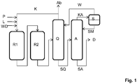
- the present invention is based on the figures Fig. 1 and Fig. 2 explained in more detail.
- Fig. 1 shows schematically (customary apparatuses such as slide valves, taps, pumps or heat exchangers have not been shown for the sake of clarity) a plant for the production of acrylic acid from propene.
- Propene P, water vapor (WD), and air (L) are fed into the first oxidation reactor R1.
- the reaction product, which contains acrolein is passed into a second oxidation reactor R2, in which the acrolein is oxidized to acrylic acid.
- the gaseous reaction product from reactor R2 is moved from the side into the quench tower Q, into which water is introduced from above.
- the gaseous top product from the quench tower can partly be fed to further processing or disposal as waste gas and partly returned to reactor R1 as cycle gas.
- the bottom product of the quench tower SQ is laterally transferred into distillation column A, in which an entrainer / azeotropic distillation is carried out.
- the top product KA is condensed and transferred to a separator S, in which the top product is separated into an aqueous phase and a phase containing the entrainer.
- the entrainer SM is returned to the distillation column A above the feed of the bottom product SQ.
- the aqueous phase W obtained in separator S is returned to the quench tower above the feed of the reaction product from reactor R2.
- the bottom product SA from column A can be fed to a further preparation D.
- Fig. 2 shows schematically a structure of an apparatus (a quench tower):
- the apparatus is provided with an inlet for the reaction mixture ZR, an inlet for the quenching agent ZQ, an outlet in the sump SQ and an outlet for the top product KQ.
- a pack P is provided, above which a means M, which ensures the formation of a liquid layer with a height of at least 1 cm, is arranged.
- the proportion of phthalic acid, isophthalic acid and terephthalic acid in the bottom product of the apparatus was determined by means of GC / MS as the dimethyl ester.
- the samples were first mixed with diazomethane for esterification.
- the samples prepared in this way were fed to the GC / MS (described below for terephthalic acid, to be carried out in an equivalent manner for phthalic acid / isophthalic acid).
- the following devices were used: liquid sampler, PAL injector 80; Agilent GC 7890 gas chromatograph and Agilent MSD 5975 mass spectrometer.
- a quench tower with a volume of 300 m 3 and an internal height of 35.05 m was used as the apparatus.
- the apparatus were 19 packs of the Montz-Pak B1-125.60 type at an internal height of 3.96 to 8.102 m, 42 packs of the Montz-Pak B1-250 packs and in 32 packs of the Montz-Pak B1-250 type from Montz were installed at an inner height of 21.97 to 28.53 m.
- the inlet for the quenching agent was installed at an internal height of 32.598 m, the reaction mixture was fed in at an internal height of 5.048 m.
- the quench tower With an inner height of 28.3 m, the quench tower had a sieve bottom with which a liquid layer of 3 cm could be created.
- the top pack was scaled down to extend from an interior height of 21.97 to 27.3 meters.
- the quench tower also had liquid distributors, gas distributors, collectors and the usual support grates for the Packs on. At the head of the quench tower there was a head take-off and a bottom drain in the bottom of the column.
- Comparative Example 1 Production of acrylic acid without the use of a quench tower according to the invention
- the plant had to be shut down after 33 days of operation because the pressure loss between the reaction mixture feed and the top take-off had risen by more than 50% compared to the value when the plant was started up.
- Example 1 Production of acrylic acid using a quench tower according to the invention.
- the acrylic acid could still be produced without any problems even after 2 months.
- no deposits whatsoever could be observed in the head of the quench tower that can be traced back to phthalic acid, terephthalic acid or isophthalic acid or their derivatives.
- Comparative example 2 Quench tower without packings and without sieve bottom:
- Comparative example 1 was repeated, using a quench tower which, instead of the B1-250 packings, had 25 Thormann trays and below that instead of the B1-125.60 packs, 7 segment cascade trays.
- Table 1 Content of diacids in the bottom product based on the overall composition of the bottom product Sum of phthalic acid and terephthalic acid Isophthalic acid Reaction mixture flow rate Comparative example 1 0.016 wt% 0.026 wt% 71 141 kg / h example 1 0.030 wt% 0.026 wt% 71 141 kg / h Comparative example 2 0.028 wt% 0.026 wt% 51 100 kg / h
- the bottom product which was obtained in an apparatus with a sieve bottom (Example 1), has a proportion of phthalic acid and terephthalic acid which is significantly higher than the proportion determined for Comparative Example 1.
- Comparative Example 2 Similar proportions of phthalic acid and terephthalic acid can be achieved as indicated for the apparatus with a sieve bottom, but only with the acceptance of a significant reduction in throughput.
Landscapes
- Chemical & Material Sciences (AREA)
- Organic Chemistry (AREA)
- Chemical Kinetics & Catalysis (AREA)
- Engineering & Computer Science (AREA)
- Oil, Petroleum & Natural Gas (AREA)
- Physics & Mathematics (AREA)
- Thermal Sciences (AREA)
- Health & Medical Sciences (AREA)
- Clinical Laboratory Science (AREA)
- Organic Low-Molecular-Weight Compounds And Preparation Thereof (AREA)
Description
- Gegenstand der vorliegenden Erfindung ist ein Verfahren zur Herstellung von Acrylsäure, welches einen Schritt der Oxidation von Acrolein aufweist, wobei das bei dieser Oxidation erhaltene Reaktionsgemisch in einer erfindungsgemäßen Apparatur mit Wasser als Quenchmittel in Kontakt gebracht wird.
- Acrylsäure (Prop-2-ensäure) ist ein Grundbaustein für die Herstellung von vornehmlich in Hygieneprodukten eingesetzten Superabsorbern sowie Rohstoff für die komplette Acrylatchemie. Acrylsäure wird im großtechnischen Maßstab durch katalytische Dampfphasenreaktion von Propen mit Sauerstoff erhalten. Dabei entstehen neben der gewünschten Acrylsäure auch unerwünschte Begleitprodukte, die bei der Weiterverarbeitung der Acrylsäure hinderlich sind. Bei diesen Begleitprodukten handelt es sich im Wesentlichen um Essigsäure, Aldehyde, Dialdehyde, Dicarbonsäuren und Wasser. Ein wichtiger Schritt bei der Herstellung von Acrylsäure (AS) besteht demnach darin, die aus der Dampfphasenreaktion stammende, acrylsäurehaltige Zusammensetzung von den unerwünschten Begleitprodukten zu reinigen, sodass reine Acrylsäure übrig bleibt. Die vorliegende Erfindung befasst sich mit einem Teilaspekt dieser Aufreinigung.
- Die Herstellung von Acrylsäure erfolgt üblicherweise klassisch chemisch über die Oxidation von Propen zum Acrolein und anschließende weitere Oxidation zur Acrylsäure. Der
EP 1319648 A1 kann ein solches Verfahren entnommen werden, bei dem die Herstellung von Acrylsäure (AS) durch katalytische Dampfphasenoxidation von Propylen in zwei Schritten erfolgt. Das Verfahren zur Herstellung von AS durch die zweistufige (die erste katalytische Oxidationsreaktionsstufe für die Umsetzung von Propylen hauptsächlich zu Acrolein und die zweite katalytische Oxidationsreaktionsstufe für die Umsetzung von Acrolein zu AS) katalytische Dampfphasenoxidation von Propylen unter Verwendung von molekularem Sauerstoff ist bereits bekannt und wird in industriellem Maßstab seit vielen Jahrzehnten durchgeführt. Aus vielen Gründen (Entflammbarkeits-Grenzen für das Gemisch Propylen/Luft und hohe Reaktionswärme) ist es notwendig, die Reaktionsgase durch Inertgase (zum Beispiel Wasserdampf, N2, CO2) zu verdünnen. Ein typisches Verfahren für die industrielle Herstellung sieht wie folgt aus: Eine Mischung aus Propylen, Luft und Dampf wird einem ersten Oxidationsreaktor zugeführt und das Propylen wird im ersten Schritt hauptsächlich zu Acrolein und in geringen Mengen zu AS umgesetzt. Das Produkt wird ohne Auftrennung einem zweiten Oxidationsreaktor zugeführt. Frische Luft und Wasserdampf können, wenn dieses für die nachfolgende Oxidationsreaktion im zweiten Oxidationsschritt erforderlich ist, am Einlass des zweiten Oxidationsreaktors zugesetzt werden. - Für die Trennung der gasförmigen AS vom Wasserdampf in dem etwa 180°C warmen Abfluss aus den Oxidationsreaktoren werden zwei Trennverfahren verwendet: 1. Absorption der gasförmigen AS in einem hochsiedenden, hydrophoben, aromatischen Lösungsmittel bei Temperaturen, unter denen das Prozesswasser im Prozess-Abluftgas, welches einen Absorptionsturm oben verlässt, verbleibt (siehe zum Beispiel
DE 43 08 087 BASF, 15.09.94) 2. Absorption der AS in Wasser bei gleichzeitigem Quenchen auf niedrige Temperaturen in einem Quenchturm/Kollektor in einer solchen Weise, dass nahezu das gesamte verdampfte Prozesswasser im 180°C-Abfluss aus dem zweiten Reaktor kondensiert (siehe zum Beispiel DE 30 42 468/Mitsubishi Chem. Corp. (MCC), 11.11.80). Während bei der ersten Verfahrensweise die AS und die hochsiedenden Produkte in vielen Destillationsschritten getrennt werden, wird bei der
zweiten Verfahrensweise das Wasser in der wässrigen AS nach dem Quenchen in einer nachfolgenden azeotropen Destillation abgetrennt, um eine Roh-AS zu erhalten, aus der AS mit hoher Reinheit für die Herstellung von AS-Copolymeren oder verschiedene AS-Ester hergestellt werden können. - Bei der zweiten Verfahrensweise, hat die Handhabung des Prozesswassers, welches aus dem bei der Oxidation gebildeten Wasser und dem Wasser für die Verdünnung, welche erforderlich ist, um außerhalb Entflammbarkeits-Grenze zu sein, besteht, einen beachtlichen Einfluss auf die Wirtschaftlichkeit des Verfahrens.
- Wenn das AS beinhaltende Produktgas, welches am Auslass des zweiten Oxidationsreaktors erhalten wird, in den Quenchturm eingebracht wird, um AS als wässrige Lösung zu erhalten, dann verlässt das resultierende Prozess-Abluftgas, welches nicht reagiertes Propylen und andere niedrig siedende organische Materialien beinhaltet, oben den Quenchturm und muss zum Beispiel in einem Verbrennungsofen behandelt werden, so dass keine oder nahezu keine organischen Verbindungen in die Luft emittiert werden (ein Durchlaufprozess mit einem Durchgang).
- Es ist auch möglich, dass ein Teil des Prozess-Abluftgases rezykliert und dem Propylen/Luft/Wasserdampf-Strom am Einlass der ersten Reaktionsstufe zugesetzt wird (Kreisgas-Strömungsprozess), was eine durchaus übliche Vorgehensweise insbesondere für den Fall darstellt, dass das Verfahren mit teilweiser Umsetzung des Propylens betrieben wird.
- In
DE 10 2010 028 781 A1 wird die weitere Auftrennung eines in einem Quenchturm erhaltenen wässrigen Acrylsäure aufweisenden Gemisches mit Hilfe einer Destillationskolonne, die einen Seitenabzug aufweist beschrieben. - In
US 7189872 wird ein Verfahren zur Herstellung von Acrylsäure beschrieben, bei dem ein Quenchturm eingesetzt wird, um Acrylsäure aus dem gasförmigen Produktgemisch abzutrennen. Dieses wässrige Gemisch wird anschließen mittels azeotroper Destillation in eine gasförmige, Wasser aufweisende Phase und eine flüssige, Acrylsäure aufweisende Phase, getrennt. -
EP 0982289 A2 offenbart eine Apparatur und ein Verfahren zur Herstellung Acrylsäure, wobei das Quenchmittel Wasser ist. -
US 6293528 B1 offenbart eine Apparatur mit Lochboden. - Bei der Acrylsäure-Herstellung durch Oxidation von Propen mit Luftsauerstoff in geringen Konzentrationen entstehen auch Nebenkomponenten, wie z. B. Phthalsäure, Therephthalsäure oder Isophthalsäure. Diese Stoffe stellen Schwersiederverbindungen dar und sind nur schlecht in Wasser löslich.
- Bei der Verwendung eines Quenchturms zur Aufbereitung des gasförmigen Produktgemisches aus dem letzten Oxidationsreaktor, fallen die genannten Nebenkomponenten im Sumpf mit der wässrigen AS an. Die Konzentration der Nebenkomponenten (Summe aus Phthalsäure, Therephthalsäure oder Isophthalsäure) beträgt 0,024 bis 0,030 Gew.-% bezogen auf die im Sumpf des Quenchturms erhaltene Zusammensetzung.
- Der Quenchturm wird häufig so ausgeführt, dass er sowohl das gasförmige Reaktionsgemisch kühlen und kondensieren, aber auch den Verlust von Acrylsäure im Kopf des Turms minimieren kann. Der Quenchturm ist deshalb üblicherweise mit Destillationsböden ausgerüstet, wie z.B. Glockenböden oder Tunnel- bzw. Thormannböden. Auch Ventilböden sieht man im Einsatz.
- Will man nun den Durchsatz durch so einen Quenchturm signifikant erhöhen oder den Kopfverlust des Zielproduktes reduzieren, so ist es bei Destillationsböden häufig üblich die Böden durch Packungen, insbesondere strukturierte Packungen zu ersetzen.
- Dabei wurde jedoch gefunden, dass jetzt nur noch ein Teil der Schwersiederverbindungen im Sumpf des Quenchturms ausgetragen wird und der andere Teil als Aerosol bzw. Desublimat bis in den Kopf der Kolonne gelangt und dort und ggf. in nachgeschalteten Apparaten zu Verstopfungen führt, so dass die Anlage nach nur einer geringen Laufzeit abgestellt werden muss, um Reinigungsarbeiten durchzuführen. Im Sumpf der Kolonne werden die oben genannten Nebenkomponenten nur noch in einer Konzentration von < 0,02 Gew-%, bezogen auf die Zusammensetzung im Sumpf des Quenchturms nachgewiesen.
- Aufgabe der vorliegenden Erfindung war es deshalb die Laufzeit des Quenchturms wieder zu verbessern, ohne dass der Durchsatz durch den Quenchturm verringert oder der Kopfverlust des Zielprodukts erhöht wird.
- Überraschenderweise wurde gefunden, dass diese Aufgabe gelöst werden kann, in dem im Quenchturm zwischen Zulauf und einer zwischen Quenchmittelzulauf und Zulauf vorhandenen Packung, mindestens ein Mittel vorgesehen wird, welches die Ausbildung einer flüssigen Schicht mit einer Höhe von mindestens 1 cm gewährleistet.
- Wesentliches Element der vorliegenden Erfindung ist deshalb eine Apparatur umfassend eine Zuführung die unterhalb der Mitte der Apparatur angeordnet ist, einen Quenchmittelzulauf, der oberhalb der Zuführung angeordnet ist, einen Ablauf, der unterhalb der Zuführung angeordnet ist, einen Abzug, der oberhalb des Quenchmittelzulaufs angeordnet ist, wobei die Apparatur zwischen Quenchmittelzulauf und Zuführung einen Bereich aufweist, der mit einer oder mehreren Packungen versehen ist, dadurch gekennzeichnet, dass zwischen dem Quenchmittelzulauf und einer zwischen Quenchmittelzulauf und Zuführung vorhandenen Packung, mindestens ein Mittel vorhanden ist, welches die Ausbildung einer flüssigen Schicht mit einer Höhe von mindestens 1 cm gewährleistet. Bei dem Mittel handelt es sich erfindungsgemäß um einen Siebboden oder um einen Wellenboden (ripple tray).
- Gegenstand der vorliegenden Erfindung ist ein Verfahren zur Herstellung von Acrylsäure, welches einen Schritt der Oxidation von Acrolein aufweist, wobei das bei dieser Oxidation erhaltene Reaktionsgemisch in genannter Apparatur mit Wasser als Quenchmittel in Kontakt gebracht wird und wobei die flüssige Schicht in der Apparatur so angeordnet ist, dass gasförmige Stoffe, die durch die Zuführung in die Apparatur gelangen, durch die flüssige Schicht hindurchtreten, um in den Kopf der Apparatur zu gelangen. Als Wasser kann z. B. vollentsalztes Wasser oder Prozesswasser verwendet werden, welches ggf. Essigsäure, Propionsäure und geringe Mengen Acrylsäure enthalten kann, aus einer nachfolgenden Wasserabtrennkolonne.
- Das erfindungsgemäße Verfahren hat den Vorteil, dass bei annähernd gleichem Durchsatz und ohne Erhöhung der Kopfverluste an Zielprodukt im Quenchturm die Laufzeit (Standzeit) erhöht wird.
- Ein weiterer Vorteil des erfindungsgemäßen Verfahrens liegt darin, dass ein Überschleppen bzw. Austragen von Dicarbonsäuren mit dem Kopfstrom vermieden oder zumindest reduziert wird, so dass die Dicarbonsäuren die weitere Aufarbeitung des Kopfprodukts nicht stören.
- Ein weiterer Vorteil des erfindungsgemäßen Verfahrens ist, dass durch die Verwendung eines Siebbodens Verstopfungen, wie sie bei der Verwendung anderer Böden auftreten, wie z. B. bei der Verwendung von Tunnelböden, vermieden werden können, woraus wiederum eine längere Laufzeit bzw. längere Wartungsintervalle resultieren. Die notwendigen Betriebsunterbrechungen werden durch die Nutzung des erfindungsgemäßen Verfahrens somit deutlich reduziert.
- Die erfindungsgemäßen Gegenstände werden nachfolgend beispielhaft beschrieben. Bei Prozentangaben handelt es sich, wenn nicht anders angegeben, um Angaben in Gewichtsprozent. Werden nachfolgend Mittelwerte angegeben, so handelt es sich, wenn nicht anderes angegeben, um Gewichtsmittel. Werden nachfolgend Parameter angegeben, die durch Messung bestimmt wurden, so wurden die Messungen, wenn nicht anders angegeben, bei einer Temperatur von 25 °C und einem Druck von 101.325 Pa durchgeführt.
- Die Apparatur, umfasst eine Zuführung, die unterhalb der Mitte der Apparatur angeordnet ist, einen Quenchmittelzulauf, der oberhalb der Zuführung angeordnet ist, einen Ablauf, der unterhalb der Zuführung angeordnet ist, einen Abzug, der oberhalb des Quenchmittelzulaufs angeordnet ist, wobei die Apparatur zwischen Quenchmittelzulauf und Zuführung einen Bereich aufweist, der mit einer oder mehreren Packungen versehen ist, zeichnet sich dadurch aus, dass zwischen dem Quenchmittelzulauf und einer zwischen Quenchmittelzulauf und Zuführung vorhandenen Packung, mindestens ein Mittel vorhanden ist, welches die Ausbildung einer flüssigen Schicht mit einer Höhe von mindestens 1 cm, vorzugsweise mit einer Höhe von 2 bis 10 cm, bevorzugt mit einer Höhe von 3 bis 5 cm, gewährleistet, wobei die flüssige Schicht erfindungsgemäß in der Apparatur so angeordnet ist, dass gasförmige Stoffe, die durch die Zuführung in die Apparatur gelangen, durch die flüssige Schicht hindurchtreten müssen, um in den Kopf der Apparatur zu gelangen, weshalb die flüssige Schicht auch als Sprudelschicht bezeichnet wird.
- Erfindungsgemäße Mittel sind Siebböden oder Wellenböden (Ripple-Tray). Bei einer Gestaltung der Mittel in der Weise, dass die aufströmenden Gase vor dem Hindurchtreten durch die flüssige Schicht über einen längere Zeit mit dem Mittel Kontakt haben, wie dies z. B. bei Glockenböden, Tunnelböden oder Thormannböden der Fall ist, kann es zu Ablagerungen von Disäuren an den Oberflächen dieser Mittel kommen. Es ist deshalb besonders vorteilhaft, als Mittel solche zu nehmen, bei denen die aufströmenden Gase ohne langen Kontakt mit dem Mittel durch die flüssige Schicht hindurchtreten, wie dies z. B. bei Wellenböden oder Siebböden der Fall ist, weshalb diese als Mittel erfindungsgemäß sind.
- Vorzugsweise sind in der Apparatur von 1 bis 5, bevorzugt 2 oder 3, besonders bevorzugt 3 der Mittel zwischen dem Quenchmittelzulauf und einer zwischen Quenchmittelzulauf und Zuführung vorhandenen Packung vorhanden.
- Als Packung(en) können in der Apparatur alle Arten von geeigneten Packungen vorhanden sein. Vorzugsweise ist die Packung bzw. sind die Packungen strukturierte Packungen oder Gewebepackungen, bevorzugt strukturierte Packungen. Geeignete Packungen werden u.a. von Sulzer unter den Handelsbezeichnungen Mellapak, von Raschig unter der Handelsbezeichnung Super-Pak, von Koch-Glitsch unter der Handelsbezeichnung Flexi-Pak sowie von Montz unter den Handelsbezeichnungen Montz-Pak vertrieben.
- Die Packung bzw. die Packungen in der Apparatur weisen vorzugsweise eine Höhe der Packung auf, die 40 bis 85 %, bevorzugt 45 bis kleiner 55 % der inneren Höhe der Apparatur beträgt. Sind mehr als eine Packung in der Apparatur vorhanden, so ergibt sich die Höhe der Packung aus der Summe der Höhen der einzelnen Packungen. Die innere Höhe der Apparatur wird durch Bestimmen der Strecke von höchstem Punkt im Kopf der Apparatur zu niedrigstem Punkt im Sumpf der Apparatur ermittelt.
- Es kann vorteilhaft sein, wenn zwischen dem untersten Mittel oberhalb der Packung und der obersten Packung ein Verteiler vorhanden ist, der die vom untersten Mittel abfließende flüssige Phase auf der Packung möglichst gleichmäßig verteilt. Ist ein solcher Verteiler vorhanden hat es sich außerdem als vorteilhaft erwiesen, wenn zwischen unterstem Mittel und Verteiler ein Sammler angeordnet ist, der die vom untersten Mittel abfließende flüssige Phase sammelt und dem Verteiler zuführt.
- Das erfindungsgemäße Verfahren zur Herstellung von Acrylsäure, welches einen Schritt der Oxidation von Acrolein aufweist, zeichnet sich dadurch aus, dass das bei dieser Oxidation erhaltene Reaktionsgemisch in einer wie oben beschrieben Apparatur mit Wasser als Quenchmittel in Kontakt gebracht wird. Als Quenchmittel kann Wasser eingesetzt werden, wie oben beschrieben.
- Als Reaktionsgemisch kann jegliches, Acrylsäure aufweisendes Gemisch, welches vorzugsweise gasförmig ist, eingesetzt werden. Geeignete Gemische können z. B. durch Verfahren zur Herstellung von Acrylsäure erhalten werden, wie sie in
DE 19740252 ,EP 0092097 ,EP 0058927 oderEP 0608838 beschrieben werden. In Bezug auf die Herstellung von Acrylsäure wird ausdrücklich auf die in den genannten Dokumenten gemachten Angaben Bezug genommen. - Das Verhältnis der Volumenströme von Quenchmittel, welches der Apparatur zugeführt wird, zu Reaktionsgemisch, welches der Apparatur zugeführt wird, beträgt vorzugsweise von 1 zu 2 bis 1 zu 20, bevorzugt von 1 zu 5 bis 1 zu 10 und besonders bevorzugt von 1 zu 7 bis 1 zu 8.
- Der Apparatur wird pro Stunde vorzugsweise von 210 kg bis 380 kg, bevorzugt von 230 kg bis 260 kg Reaktionsgemisch pro m3 Apparaturvolumen zugeführt. Das Apparaturvolumen ist das Volumen der Apparatur minus dem Volumen der Einbauten. Das Apparaturvolumen kann durch Füllen der Apparatur mit einer Flüssigkeit bestimmt werden.
- Die Temperatur der flüssigen Phase auf dem Mittel beträgt vorzugsweise von 50 °C bis 100 °C, bevorzugt von 60 °C bis 90 °C und besonders bevorzugt von 70 °C bis 80 °C. Die Temperatur kann durch Variation der Volumenströme sowie durch die der Apparatur zugeführte Wärmeenergie eingestellt werden.
- In dem erfindungsgemäßen Verfahren wird die Apparatur vorzugsweise so betrieben, dass die Druckdifferenz zwischen dem Druck, gemessen am Kopf der Apparatur und dem Druck, gemessen im Gasraum oberhalb der flüssigen Phase im Sumpf der Apparatur von 10 mbar bis 60 mbar, bevorzugt von 30 mbar bis 40 mbar beträgt.
- Mittels des erfindungsgemäßen Verfahrens sind Zusammensetzungen (Produktgemische) erhältlich, die überwiegend Acrylsäure und Wasser enthalten. Vorzugsweise wird die Zusammensetzung als Sumpfprodukt (der erfindungsgemäß eingesetzten Apparatur) in dem erfindungsgemäßen Verfahren erhalten. Die Zusammensetzung enthält vorzugsweise Acrylsäure, Wasser, Phthalsäure, Terephthalsäure und Isophthalsäure, wobei der Anteil der Summe aus Phthalsäure, Terephthalsäure und Isophthalsäure vorzugsweise größer 0,05 Gew.-%, bevorzugt von 0,05 bis 1 Gew.-% und besonders bevorzugt von 0,052 bis 0,075 Gew.-% bezogen auf die Zusammensetzung beträgt. Die Summe aus Wasser und Acrylsäure beträgt vorzugsweise größer 90 Gew.-%, bevorzugt größer 95 Gew.-% bezogen auf die Zusammensetzung. Der Anteil an Acrylsäure an der Zusammensetzung beträgt vorzugsweise von 50 bis 65 Gew.-%, bevorzugt 53 bis 62 Gew.-% bezogen auf die Zusammensetzung. Der bevorzugte Anteil an Wasser ergibt sich aus den für die Summe aus Acrylsäure und Wasser angegebenen Werten entsprechend. Besonders bevorzugte Zusammensetzungen weisen einen Anteil der Summe aus Phthalsäure, Terephthalsäure und Isophthalsäure von vorzugsweise größer 0,05 Gew.-%, bevorzugt von 0,05 bis 1 Gew.-% und besonders bevorzugt von 0,052 bis 0,075 Gew.-% bezogen auf die Zusammensetzung und einen Anteil der Summe aus Wasser und Acrylsäure von vorzugsweise größer 90 Gew.-%, bevorzugt größer 95 Gew.-% bezogen auf die Zusammensetzung. Als weitere Komponenten können die Zusammensetzungen Essigsäure, Maleinsäure, Hydrochinon, Di-Acrylsäure, Formaldehyd und Propionsäure aufweisen. Besonders bevorzugte Zusammensetzungen weisen von 2 bis 3 Gew.-% Essigsäure, von 0,1 bis 0,3 Gew.-% Maleinsäure, von 0,03 bis 0,1 Gew.-% Hydrochinon, von 0,15 bis 0,25 Gew.-% Di-Acrylsäure, von 0,5 bis 1,25 Gew.-% Formaldehyd und von 0,01 bis 0,05 Gew.-% Propionsäure, jeweils bezogen auf die Zusammensetzung auf.
- Die erhaltenen Zusammensetzungen (Produktgemische) können einer weiteren Aufarbeitung zugeführt werden. Insbesondere kann die Aufarbeitung der Zusammensetzung wie in
DE 10 2010 028 781 A1 oderUS 7189872 beschrieben, auf welche ausdrücklich Bezug genommen wird, erfolgen. - Die vorliegende Erfindung wird anhand der Figuren
Fig. 1 undFig. 2 näher erläutert. -
Fig. 1 zeigt schematisch (Übliche Apparaturen wie z.B. Schieber, Hähne, Pumpen oder Wärmetauscher wurden der besseren Übersichtlichkeit halber nicht dargestellt) eine Anlage zur Herstellung von Acrylsäure aus Propen. In den ersten Oxidationsreaktor R1 werden Propen P, Wasserdampf (WD), und Luft (L) geleitet. Das Reaktionsprodukt, welches Acrolein enthält, wird in einen zweiten Oxidationsreaktor R2 geleitet, in dem das Acrolein zur Acrylsäure oxidiert wird. Das gasförmige Reaktionsprodukt aus Reaktor R2 wird seitlich in den Quenchturm Q gefahren, in den von oben Wasser eingeleitet wird. Das gasförmige Kopfprodukt aus dem Quenchturm kann teilweise als Abgas einer weitere Aufarbeitung oder Entsorgung zugeführt und teilweise als Kreisgas in den Reaktor R1 zurückgefahren werden. Das Sumpfprodukt des Quenchturms SQ wird seitlich in Destillationskolonne A überführt, in der eine Schleppmittel-/AzeotropDestillation durchgeführt wird. Das Kopfprodukt KA wird kondensiert und in einen Abscheider S überführt, in dem das Kopfprodukt in eine wässrige Phase und eine das Schleppmittel aufweisende Phase getrennt wird. Das Schleppmittel SM wird in die Destillationskolonne A oberhalb der Einspeisung des Sumpfprodukts SQ zurückgeführt. Die im Abscheider S erhaltene wässrige Phase W wird in den Quenchturm oberhalb der Einspeisung des Reaktionsproduktes aus dem Reaktor R2 zurückgeführt. Das Sumpfprodukt SA der Kolonne A kann einer weitere Aufbereitung D zugeführt werden. -
Fig. 2 zeigt schematisch einen Aufbau einer Apparatur (eines Quenchturms): Die Apparatur ist mit einer Zuführung für das Reaktionsgemisch ZR, einem Zulauf für das Quenchmittel ZQ, einem Ablauf im Sumpf SQ und einem Abzug für das Kopfprodukt KQ versehen. Im inneren ist eine Packung P vorgesehen, über dem ein Mittel M, welches die Ausbildung einer flüssigen Schicht mit einer Höhe von mindestens 1 cm gewährleistet, angeordnet ist. - In den nachfolgend aufgeführten Beispielen wird die vorliegende Erfindung beispielhaft beschrieben.
- Die Bestimmung des Anteils an Phthalsäure, Isophthalsäure und Terephthalsäure im Sumpfprodukt der Apparatur erfolgte mittels GC/MS als Dimethylester. Dazu wurden die Proben zur Veresterung zunächst mit Diazomethan versetzt. Die so präparierten Proben wurden dem GC/MS zugeführt (Nachfolgend beschrieben für Terephthalsäure, äquivalent durchzuführen für Phthalsäure/Isophthalsäure). Folgende Geräte wurden verwendet: Flüssigprobengeber, PAL Injektor 80; Gaschromatograph Agilent GC 7890 und Massenspektrometer Agilent MSD 5975.
- Die Messungen erfolgten mit folgenden Parametern:
- Kapillarsäule: 30 m DB-5; 0,25 mm Innendurchmesser; 0,25 µm Film
- Trägergas: Helium
- Säulenfluss: ca. 1 ml/min
- Injektor: 300°C (0,5 min splitlos, dann 50 ml/min)
- Ofentemperatur: 60°C - 8°C/min - 250°C (15 min)
- Injektionsvolumen: 1,0 µl
- Detektor (MSD): Single-Ion-Monitoring (SIM)
- Gruppe 1 (6 min bis12 min): (91,0; 100 msec), (119,0; 100 msec), (150; 100 msec)
- Gruppe 2 (ab 12 min): (163,0; 100 msec), (194,0; 100 msec)
- Als Reagenzien wurden eingesetzt:
- Derivatisierungsmittel Diazomethan
- Methanol
- Dotierlösung Terephthalsäure (Konzentration = 1 mg/ml, gelöst in Methanol)
- 25 mg Probe wurden in 1 ml Methanol gelöst und mit Diazomethan derivatisiert. Das Reaktionsgemisch wird danach im Wasserbad bis auf 1,5 ml eingeengt. Die gesamte Lösung wird in einen 2 ml-Messkolben überführt und bis zur Markierung mit Methanol aufgefüllt.
- 25 mg Probe wurden in 1 ml Methanol gelöst, mit 10 µL der Dotierlösung Terephthalsäure versetzt und im Anschluss mit Diazomethan derivatisiert. Das Reaktionsgemisch wird danach im Wasserbad bis auf 1,5 ml eingeengt. Die gesamte Lösung wird in einen 2 ml-Messkolben überführt und bis zur Markierung mit Methanol aufgefüllt.
- Der Nachweis der Terephthalsäure erfolgte in der GC/MS-Analyse als Dimethylterephthalat. Der Dimethylterephthalat-Peak wird anhand der Laufzeit und anhand des Verhältnisses der beiden gemessenen Ionen m/z 163 und m/z 194 (zwei charakteristische Ionen für Dimethylterephthalat) identifiziert. Zur Berechnung des Massengehaltes an Terephthalsäure in der Probe werden die Messwerte aus der Messung der undotierten und aus der dotierten Probe herangezogen werden:

- w(T): Massenanteil an Terephthalsäure in der Probe (in mg/g)
- m(T, dot.): Masse an dotierter Terephthalsäure in der dotierten Probe (in µg)
- A(T, dot.): Peakfläche des Dimethylterephthalat in der dotierten Probe
- E(dot.): Einwaage Probe der dotierten Messung (in mg)
- A(T): Peakfläche an Dimethylterephthalat in der undotierten Probe
- E: Einwaage Probe der undotierten Messung (in mg)
- Als Apparatur wurde ein Quenchturm mit einem Volumen von 300 m3 und einer inneren Höhe von 35,05 m eingesetzt. In der Apparatur waren in einer inneren Höhe von 3,96 bis 8,102 m 19 Packungen vom Typ Montz-Pak B1-125,60, in einer inneren Höhe von 10,975 bis 19,585 m 42 Packungen vom Typ Montz-Pak B1-250 Packungen und in einer inneren Höhe von 21,97 bis 28,53 m 32 Packungen vom Typ Montz-Pak B1-250 der Firma Montz installiert. Der Zulauf für das Quenchmittel war bei einer inneren Höhe von 32,598 m installiert, die Zuführung des Reaktionsgemisches erfolgte bei einer inneren Höhe von 5,048 m. Im Vergleichsbeispiel wurde ein solcher Quenchturm, der keinen Siebboden aufwies, eingesetzt. Der Quenchturm wies bei einer inneren Höhe von 28,3 m einen Siebboden auf, mit dem sich eine flüssige Schicht von 3 cm realisieren ließ. Die oberste Packung wurde verkleinert, so dass sie von einer inneren Höhe von 21,97 bis 27,3 m reichte. Der Quenchturm wies des weiteren Flüssigkeitsverteiler, Gasverteiler, Sammler sowie übliche Auflageroste für die Packungen auf. Am Kopf des Quenchturms war ein Kopfabzug vorhanden und im Sumpf der Kolonne ein Sumpfablauf.
- In einer wie in
Fig. 1 schematisch dargestellten Anlage zur Herstellung von Acrylsäure wurde ein Reaktionsgemischstrom, der 6,24 Vol.-% Acrylsäure und einen Gehalt der Summe aus Phthalsäure, Isophthalsäure und Terephthalsäure von 0,0144 Gew.-% aufwies, mit 71141 kg/h in den Quenchturm geleitet. Über den Zulauf für das Quenchmittel wurden 8200 kg/h an Wasser zugeführt. Über den Sumpfablauf wurde ein Produktstrom von 18252 kg/h entnommen. Über den Kopfabzug wurde ein Abgasstrom von 61089 kg/h entnommen. Die Sumpftemperatur wurde auf 79,1 °C und die Kopftemperatur auf 71,6 °C eingestellt. Nach dreistündigem kontinuierlichem Betrieb wurden die Proben aus dem Sumpf gezogen. Die Ergebnisse der Analyse sind in Tabelle 1 angegeben. - Die Anlage musste nach 33 Betriebstagen abgestellt werden, da der Druckverlust zwischen Reaktionsgemischzuführung und Kopfabzug um mehr als 50 % gegenüber dem Wert beim Anfahren der Anlage gestiegen war.
- In einer wie im Vergleichsbeispiel beschriebenen Anlage wurde an Stelle des dort beschriebenen Quenchturms ein Quenchturm eingesetzt, der einen Siebboden aufwies. Nach dreistündigem kontinuierlichem Betrieb wurden die Proben aus dem Sumpf gezogen. Die Ergebnisse der Analyse sind wiederum in Tabelle 1 angegeben.
- Im Gegensatz zum Vergleichsversuch konnte die Herstellung der Acrylsäure auch nach 2 Monaten noch problemlos durchgeführt werden. Bei einer standardmäßigen Revision der Anlage nach 3 Monaten konnten im Kopf des Quenchturms keinerlei Ablagerungen beobachtet werden, die auf Phthalsäure, Terephthalsäure oder Isophthalsäure oder Folgeprodukten davon, zurückgeführt werden können.
- Das Vergleichsbeispiel 1 wurde wiederholt, wobei ein Quenchturm eingesetzt wurde, der statt der B1-250 Packungen 25 Thormann-Böden und darunter an Stelle der B1-125,60 Packungen 7 Segmentkaskadenböden aufwies.
Tabelle 1: Gehalt an Disäuren im Sumpfprodukt bezogen auf die Gesamtzusammensetzung des Sumpfproduktes Summe Phthalsäure und Terephthalsäure Isophthalsäure Durchsatz Reaktionsgemischstrom Vergleichsbeispiel 1 0,016 Gew.-% 0,026 Gew.-% 71141 kg/h Beispiel 1 0,030 Gew.-% 0,026 Gew.-% 71141 kg/h Vergleichsbeispiel 2 0,028 Gew.-% 0,026 Gew.-% 51100 kg/h - Wie der Tabelle 1 entnommen werden kann, weist das Sumpfprodukt, welches in einer Apparatus mit einem Siebboden (Beispiel 1) erhalten wurde, einen Anteil an Phthalsäure und Terephthalsäure auf, der deutlich höher liegt als der Anteil, der für das Vergleichsbeispiel 1 bestimmt wurde. Mit einem Quenchturm ohne Packungen (Vergleichsbeispiel 2) können zwar ähnliche Anteile an Phthalsäure und Terephthalsäure erreicht werden, wie für die Apparatur mit Siebboden angegeben, allerdings nur unter Hinnahme von einer deutlichen Verringerung beim Durchsatz.
Claims (11)
- Verfahren zur Herstellung von Acrylsäure, welches einen Schritt der Oxidation von Acrolein aufweist, wobei das bei dieser Oxidation erhaltene Reaktionsgemisch in einer Apparatur mit Wasser als Quenchmittel in Kontakt gebracht wird, und wobei die Apparatur die folgenden Merkmale umfasst:
eine Zuführung die unterhalb der Mitte der Apparatur angeordnet ist, einen Quenchmittelzulauf, der oberhalb der Zuführung angeordnet ist, einen Ablauf, der unterhalb der Zuführung angeordnet ist, einen Abzug, der oberhalb des Quenchmittelzulaufs angeordnet ist, wobei die Apparatur zwischen Quenchmittelzulauf und Zuführung einen Bereich aufweist, der mit einer oder mehreren Packungen versehen ist, wobei zwischen dem Quenchmittelzulauf und einer zwischen Quenchmittelzulauf und Zuführung vorhandenen Packung, mindestens ein Mittel vorhanden ist, welches eine flüssige Schicht mit einer Höhe von mindestens 1 cm ausbildet, wobei die flüssige Schicht in der Apparatur so angeordnet ist, dass gasförmige Stoffe, die durch die Zuführung in die Apparatur gelangen, durch die flüssige Schicht hindurchtreten, um in den Kopf der Apparatur zu gelangen, wobei das Mittel ein Wellenboden oder ein Siebboden ist. - Verfahren nach Anspruch 1, dadurch gekennzeichnet, dass die flüssige Schicht eine Höhe von 2 bis 10 cm, vorzugsweise von 3 bis 8 cm aufweist.
- Verfahren nach zumindest einem der Ansprüche 1 bis 2, dadurch gekennzeichnet, dass die Packung eine strukturierte Packung oder eine Gewebepackung, bevorzugt eine strukturierte Packung ist.
- Verfahren nach zumindest einem der Ansprüche 1 bis 3, dadurch gekennzeichnet, dass die Packung eine Höhe aufweist, die 50 bis 85 % der inneren Höhe der Apparatur beträgt.
- Verfahren nach zumindest einem der Ansprüche 1 bis 4, dadurch gekennzeichnet, dass 1 bis 5, bevorzugt 2 oder 3, besonders bevorzugt 3 der Mittel zwischen dem Quenchmittelzulauf und einer zwischen Quenchmittelzulauf und Zuführung vorhandenen Packung vorhanden sind.
- Verfahren nach zumindest einem der Ansprüche 1 bis 5, dadurch gekennzeichnet, dass zwischen dem untersten Mittel und der obersten Packung ein Verteiler vorhanden ist, der die vom untersten Mittel abfließende flüssige Phase auf der Packung möglichst gleichmäßig verteilt.
- Verfahren nach Anspruch 6, dadurch gekennzeichnet, dass zwischen unterstem Mittel und Verteiler ein Sammler angeordnet ist, der die vom untersten Mittel abfließende flüssige Phase sammelt und dem Verteiler zuführt.
- Verfahren nach Anspruch 1, dadurch gekennzeichnet, dass das Verhältnis der Volumenströme von Quenchmittel, welches der Apparatur zugeführt wird, zu Reaktionsgemisch, welches der Apparatur zugeführt wird, von 1 zu 2 bis 1 zu 20, bevorzugt von 1 zu 5 bis 1 zu 10 beträgt.
- Verfahren nach Anspruch 1 oder 8, dadurch gekennzeichnet, dass die Temperatur der flüssigen Phase auf dem Mittel von 50 °C bis 100 °C, bevorzugt von 70 °C bis 80 °C beträgt.
- Verfahren nach zumindest einem der Ansprüche 1 oder 8 oder 9, dadurch gekennzeichnet, dass die Apparatur so betrieben wird, dass die Druckdifferenz zwischen dem Druck, gemessen am Kopf der Apparatur und dem Druck, gemessen im Gasraum oberhalb der flüssigen Phase im Sumpf der Apparatur von 10 mbar bis 60 mbar, bevorzugt von 30 mbar bis 40 mbar beträgt.
- Verfahren nach zumindest einem der Ansprüche 1 oder 8 oder 9 oder 10, dadurch gekennzeichnet, dass der Apparatur pro Stunde von 210 bis 380 kg Reaktionsgemisch pro m3 Apparaturvolumen zugeführt wird.
Applications Claiming Priority (2)
| Application Number | Priority Date | Filing Date | Title |
|---|---|---|---|
| DE102013217386.5A DE102013217386A1 (de) | 2013-09-02 | 2013-09-02 | Verfahren zur Herstellung von Acrylsäure |
| PCT/EP2014/067137 WO2015028293A2 (de) | 2013-09-02 | 2014-08-11 | Verfahren zur herstellung von acrylsäure |
Publications (2)
| Publication Number | Publication Date |
|---|---|
| EP3041603A2 EP3041603A2 (de) | 2016-07-13 |
| EP3041603B1 true EP3041603B1 (de) | 2021-09-29 |
Family
ID=51399617
Family Applications (1)
| Application Number | Title | Priority Date | Filing Date |
|---|---|---|---|
| EP14755605.4A Active EP3041603B1 (de) | 2013-09-02 | 2014-08-11 | Verfahren zur herstellung von acrylsäure |
Country Status (4)
| Country | Link |
|---|---|
| US (1) | US10479751B2 (de) |
| EP (1) | EP3041603B1 (de) |
| DE (1) | DE102013217386A1 (de) |
| WO (1) | WO2015028293A2 (de) |
Families Citing this family (3)
| Publication number | Priority date | Publication date | Assignee | Title |
|---|---|---|---|---|
| DE102013217386A1 (de) | 2013-09-02 | 2015-03-05 | Evonik Industries Ag | Verfahren zur Herstellung von Acrylsäure |
| US10647650B2 (en) | 2018-10-05 | 2020-05-12 | Evonik Operations Gmbh | Process for hydroformylating short-chain olefins using a heterogenized catalyst system without ionic liquid |
| US10654784B2 (en) | 2018-10-05 | 2020-05-19 | Evonik Operations Gmbh | Process for hydroformylating short-chain olefins in the gas phase |
Family Cites Families (43)
| Publication number | Priority date | Publication date | Assignee | Title |
|---|---|---|---|---|
| JPS5673041A (en) | 1979-11-19 | 1981-06-17 | Mitsubishi Petrochem Co Ltd | Preparation of acrylic acid |
| DE3106557A1 (de) | 1981-02-21 | 1982-09-16 | Basf Ag, 6700 Ludwigshafen | Verfahren zur herstellung von (alpha)-alkylacroleinen |
| DE3213681A1 (de) | 1982-04-14 | 1983-10-27 | Basf Ag, 6700 Ludwigshafen | Verfahren zur herstellung von (alpha)-alkylacroleinen |
| MX168173B (es) * | 1983-06-21 | 1993-05-07 | Glitsch | Empaque de metal foraminado y metodo para manufacturarlo |
| US4744929A (en) * | 1986-07-17 | 1988-05-17 | Norton Company | Support device for a packed column |
| US4774929A (en) * | 1986-10-09 | 1988-10-04 | The Coleman Company, Inc. | Gun with pivoting barrel and lever for retaining barrel in position or permitting barrel to pviot |
| EP0608838B1 (de) | 1993-01-28 | 1997-04-16 | Mitsubishi Chemical Corporation | Methode zur Herstellung einer ungesättigten Carbonsäure |
| DE4308087C2 (de) | 1993-03-13 | 1997-02-06 | Basf Ag | Verfahren zur Abtrennung von Acrylsäure aus den Reaktionsgasen der katalytischen Oxidation von Propylen und/oder Acrolein |
| SG71815A1 (en) * | 1997-07-08 | 2000-04-18 | Asahi Chemical Ind | Method of producing methyl methacrylate |
| DE19740252A1 (de) | 1997-09-12 | 1999-03-18 | Basf Ag | Verfahren zur Herstellung von Acrylsäure und Methacrylsäure |
| JP3948798B2 (ja) * | 1997-10-27 | 2007-07-25 | 株式会社日本触媒 | アクリル酸の製造方法 |
| US6293528B1 (en) * | 1998-04-23 | 2001-09-25 | Uop Llc | Fractionation apparatus with low surface area grid above tray deck |
| DE19838817A1 (de) | 1998-08-26 | 2000-03-02 | Basf Ag | Verfahren zur kontinuierlichen Gewinnung von (Meth)acrylsäure |
| US6513945B1 (en) * | 2001-07-16 | 2003-02-04 | John Raymond Wyss | Decorative illuminated pumpkin stems |
| ZA200209651B (en) * | 2001-12-10 | 2003-06-03 | Nippon Catalytic Chem Ind | Method and apparatus for absorbing (Meth)acrylic acid. |
| EP1319648B1 (de) | 2001-12-14 | 2008-04-02 | Stockhausen GmbH | Verfahren zur Herstellung von Acrylsäure |
| JP4016650B2 (ja) | 2001-12-14 | 2007-12-05 | 三菱化学株式会社 | (メタ)アクリル酸の製造方法 |
| DE10211686A1 (de) | 2002-03-15 | 2003-10-02 | Stockhausen Chem Fab Gmbh | (Meth)Acrylsäurekristall und Verfahren zur Herstellung und Aufreinigung von wässriger (Meth)Acrylsäure |
| DE102004005863A1 (de) | 2004-02-05 | 2005-09-08 | Stockhausen Gmbh | Reaktor mit einem einen Einsatz aufweisenden Wärmetauscherbereich |
| DE102004008575A1 (de) | 2004-02-19 | 2005-09-08 | Stockhausen Gmbh | Spaltung oligomerer (Meth)acrylsäure in flüssiger Phase unter Druck |
| DE102004015714B3 (de) | 2004-03-29 | 2005-12-15 | Stockhausen Gmbh | Trennboden für eine Destillationskolonne |
| DE102004015727B3 (de) | 2004-03-29 | 2005-12-15 | Stockhausen Gmbh | Destillationskolonne |
| DE102004034316B4 (de) | 2004-07-15 | 2015-07-16 | Evonik Degussa Gmbh | Ein Verfahren zur Herstellung von (Meth)Acrylsäure |
| TWI522092B (zh) | 2005-02-28 | 2016-02-21 | 贏創德固賽有限責任公司 | 丙烯酸和基於可再生原料之吸水聚合物結構及二者之製備方法 |
| TWI529181B (zh) | 2005-02-28 | 2016-04-11 | 贏創德固賽有限責任公司 | 以可更新原料為基之吸水聚合物結構及其生產的方法 |
| DE102005030416B4 (de) | 2005-06-30 | 2007-06-21 | Stockhausen Gmbh | Anordnung und Verfahren zur Erwärmung und Begasung eines polymerisationsfähigen Stoffes sowie Vorrichtung und Verfahren zur Herstellung hochreiner (Meth)Acrylsäure |
| US20090068440A1 (en) | 2005-06-20 | 2009-03-12 | Gunther Bub | Production of acrolein, acrylic acid and water-absorbent polymer structures made from glycerine |
| DE102005030414A1 (de) | 2005-06-30 | 2007-01-18 | Stockhausen Gmbh | Reaktor und Verfahren zur katalytischen Gasphasenreaktion sowie Verfahren zur Applikation eines Katalysators in einem Reaktor |
| DE102005039156B4 (de) | 2005-08-17 | 2014-12-24 | Evonik Degussa Gmbh | Verfahren zur Herstellung von (Meth)Acrylsäure mit Schwersiedeaufarbeitung durch Kristallisation |
| DE102006039203B4 (de) | 2006-08-22 | 2014-06-18 | Evonik Degussa Gmbh | Verfahren zur Herstellung von durch Kristallisation gereinigter Acrylsäure aus Hydroxypropionsäure sowie Vorrichtung dazu |
| DE102006039205A1 (de) | 2006-08-22 | 2008-03-20 | Stockhausen Gmbh | Auf nachwachsenden Rohstoffen basierende Acrylsäure und wasserabsorbierende Polymergebilde sowie Verfahren zu deren Herstellung mittels Dehydratisierung |
| BRPI0806767A2 (pt) * | 2007-01-26 | 2011-09-13 | Basf Se | processo para preparar ácido acrìlico |
| EP1995231B1 (de) * | 2007-05-25 | 2013-11-20 | Evonik Röhm GmbH | Verfahren zur Herstellung von Methylmethacrylat unter Verwendung von wiederaufbereitetem Methanol |
| CN101909808B (zh) | 2008-01-17 | 2014-04-30 | 本田技研工业株式会社 | 激光加工装置和激光加工方法 |
| EP2085376B1 (de) | 2008-01-30 | 2012-09-05 | Evonik Röhm GmbH | Verfahren zur Herstellung hochreiner Methacrylsäure |
| DE102008020688B3 (de) | 2008-04-24 | 2009-11-05 | Evonik Stockhausen Gmbh | Verfahren zur Herstellung und Aufreinigung wässriger Phasen |
| DE102008044946B4 (de) | 2008-08-29 | 2022-06-15 | Evonik Superabsorber Gmbh | Einsatz von Schaumkörpern in Oxidations-Reaktoren zur Herstellung ungesättigter Carbonsäuren |
| DE102008060218A1 (de) | 2008-12-04 | 2010-06-10 | Evonik Stockhausen Gmbh | Aufarbeitungsverfahren bei der Herstellung von (Meth)Acrylsäurealkylestern |
| DE102008060888A1 (de) | 2008-12-09 | 2010-06-10 | Evonik Stockhausen Gmbh | Verfahren zur Herstellung von Acrolein umfassend die Aufarbeitung einer Rohglycerin-Phase |
| DE102010028781A1 (de) | 2010-05-10 | 2011-11-10 | Evonik Stockhausen Gmbh | Abtrennung von Acrylsäure mittels einer einen Seitenabzug aufweisenden Destillationskolonne |
| DE102010062601A1 (de) | 2010-12-08 | 2012-06-14 | Evonik Stockhausen Gmbh | Verfahren zur Herstellung von (Meth)Acrylsäureestern |
| DE102013000602A1 (de) | 2013-01-16 | 2014-07-17 | Evonik Industries Ag | Verfahren zur Herstellung von Acrylsäure |
| DE102013217386A1 (de) | 2013-09-02 | 2015-03-05 | Evonik Industries Ag | Verfahren zur Herstellung von Acrylsäure |
-
2013
- 2013-09-02 DE DE102013217386.5A patent/DE102013217386A1/de active Pending
-
2014
- 2014-08-11 WO PCT/EP2014/067137 patent/WO2015028293A2/de not_active Ceased
- 2014-08-11 EP EP14755605.4A patent/EP3041603B1/de active Active
- 2014-08-11 US US14/915,929 patent/US10479751B2/en active Active
Also Published As
| Publication number | Publication date |
|---|---|
| US20160257637A1 (en) | 2016-09-08 |
| WO2015028293A2 (de) | 2015-03-05 |
| EP3041603A2 (de) | 2016-07-13 |
| DE102013217386A1 (de) | 2015-03-05 |
| WO2015028293A3 (de) | 2015-05-07 |
| US10479751B2 (en) | 2019-11-19 |
Similar Documents
| Publication | Publication Date | Title |
|---|---|---|
| DE69509451T2 (de) | Reinigung der Acrylsäure durch azeotropische Destillation | |
| EP3492446B1 (de) | Verfahren zur gewinnung von alkoholen aus aldehyden | |
| EP2118044B1 (de) | Verfahren zur herstellung von sehr reinem 1,4-butandiol | |
| DE19838817A1 (de) | Verfahren zur kontinuierlichen Gewinnung von (Meth)acrylsäure | |
| DE112023001404T5 (de) | Halbleiter-reinigungsflüssigkeit und verfahren zur herstellung einer halbleiter-reinigungsflüssigkeit | |
| DE102014011476A1 (de) | Verfahren zur Herstellung von Acrylsäure aus Methanol und Essigsäure | |
| EP1294672B1 (de) | Verfahren zur herstellung von hydroformylierungsprodukten des propylens und von acrylsäure und/oder acrolein | |
| EP2569271B1 (de) | Verfahren zur herstellung von neopentylglykol | |
| DE102013217386A1 (de) | Verfahren zur Herstellung von Acrylsäure | |
| DE2451990C3 (de) | Verfahren zur Herstellung von konzentrierten, wäßrigen Lösungen von Formaleyhd und Harnstoff | |
| DE2547536C2 (de) | Verfahren zur Herstellung von Methacrylsäure | |
| EP1879846B1 (de) | Verfahren der rektifikativen auftrennung einer acrylsäure und/oder methacrylsäure enthaltenden flüssigkeit | |
| WO2021115813A1 (de) | Verfahren zur herstellung von 1,4-butandiol, gamma-butyrolacton und tetrahydrofuran in der gasphase unter vermeidung von polymeren ablagerungen | |
| EP1838405B1 (de) | Verfahren zur herstellung von spezifikationsgerechtem phthalsäureanhydrid | |
| DE2442231C2 (de) | Verfahren zur Herstellung von Formaldehyd | |
| DE4003232A1 (de) | Verfahren zur herstellung von tertiaeren carbonsaeuren | |
| DE102004053184B4 (de) | Verfahren zur Sättigung ethylenhaltiger Gase mit Essigsäure | |
| EP0581222B1 (de) | Verfahren zur Abtrennung von Methacrolein aus einem gasförmigen Gemisch | |
| EP1233012B1 (de) | Verfahren zur herstellung von spezifikationsgerechtem phthalsäureanhydrid | |
| DE3900479A1 (de) | Verfahren zur herstellung von 1,3-dioxan-5-on und dihydroxyaceton | |
| DE19950991A1 (de) | Verfahren zum destillativen Reinigen von rohem 1,4-Butandiol | |
| DE2513678C3 (de) | Verfahren zur Herstellung von praktisch ameisensäurefreier Essigsäure | |
| DE2838880A1 (de) | Verfahren zur gewinnung von methacrolein | |
| DE102007042381B3 (de) | Verfahren zur selektiven Herstellung von linearen Diglycerinen | |
| EP0017206A1 (de) | Verfahren zur gleichzeitigen Herstellung von konzentrierten, wässrigen Formaldehyd/Harnstoff-Lösungen und Formaldehydlösungen |
Legal Events
| Date | Code | Title | Description |
|---|---|---|---|
| PUAI | Public reference made under article 153(3) epc to a published international application that has entered the european phase |
Free format text: ORIGINAL CODE: 0009012 |
|
| 17P | Request for examination filed |
Effective date: 20160210 |
|
| AK | Designated contracting states |
Kind code of ref document: A2 Designated state(s): AL AT BE BG CH CY CZ DE DK EE ES FI FR GB GR HR HU IE IS IT LI LT LU LV MC MK MT NL NO PL PT RO RS SE SI SK SM TR |
|
| AX | Request for extension of the european patent |
Extension state: BA ME |
|
| DAX | Request for extension of the european patent (deleted) | ||
| STAA | Information on the status of an ep patent application or granted ep patent |
Free format text: STATUS: EXAMINATION IS IN PROGRESS |
|
| 17Q | First examination report despatched |
Effective date: 20190809 |
|
| RAP1 | Party data changed (applicant data changed or rights of an application transferred) |
Owner name: EVONIK OPERATIONS GMBH Owner name: ELDER, JAMES EDWARD |
|
| RAP1 | Party data changed (applicant data changed or rights of an application transferred) |
Owner name: EVONIK OPERATIONS GMBH |
|
| GRAP | Despatch of communication of intention to grant a patent |
Free format text: ORIGINAL CODE: EPIDOSNIGR1 |
|
| STAA | Information on the status of an ep patent application or granted ep patent |
Free format text: STATUS: GRANT OF PATENT IS INTENDED |
|
| RIC1 | Information provided on ipc code assigned before grant |
Ipc: B01D 3/14 20060101ALI20210226BHEP Ipc: C07C 51/25 20060101ALI20210226BHEP Ipc: B01J 19/30 20060101AFI20210226BHEP Ipc: B01D 3/00 20060101ALI20210226BHEP Ipc: B01D 3/16 20060101ALI20210226BHEP Ipc: C07C 51/48 20060101ALI20210226BHEP |
|
| INTG | Intention to grant announced |
Effective date: 20210322 |
|
| GRAS | Grant fee paid |
Free format text: ORIGINAL CODE: EPIDOSNIGR3 |
|
| GRAA | (expected) grant |
Free format text: ORIGINAL CODE: 0009210 |
|
| STAA | Information on the status of an ep patent application or granted ep patent |
Free format text: STATUS: THE PATENT HAS BEEN GRANTED |
|
| AK | Designated contracting states |
Kind code of ref document: B1 Designated state(s): AL AT BE BG CH CY CZ DE DK EE ES FI FR GB GR HR HU IE IS IT LI LT LU LV MC MK MT NL NO PL PT RO RS SE SI SK SM TR |
|
| REG | Reference to a national code |
Ref country code: GB Ref legal event code: FG4D Free format text: NOT ENGLISH |
|
| REG | Reference to a national code |
Ref country code: DE Ref legal event code: R096 Ref document number: 502014015910 Country of ref document: DE |
|
| REG | Reference to a national code |
Ref country code: CH Ref legal event code: EP Ref country code: AT Ref legal event code: REF Ref document number: 1433724 Country of ref document: AT Kind code of ref document: T Effective date: 20211015 |
|
| REG | Reference to a national code |
Ref country code: IE Ref legal event code: FG4D Free format text: LANGUAGE OF EP DOCUMENT: GERMAN |
|
| RAP2 | Party data changed (patent owner data changed or rights of a patent transferred) |
Owner name: EVONIK SUPERABSORBER GMBH |
|
| REG | Reference to a national code |
Ref country code: LT Ref legal event code: MG9D |
|
| REG | Reference to a national code |
Ref country code: DE Ref legal event code: R081 Ref document number: 502014015910 Country of ref document: DE Owner name: EVONIK SUPERABSORBER GMBH, DE Free format text: FORMER OWNER: EVONIK OPERATIONS GMBH, 45128 ESSEN, DE Ref country code: DE Ref legal event code: R081 Ref document number: 502014015910 Country of ref document: DE Owner name: STOCKHAUSEN SUPERABSORBER GMBH, DE Free format text: FORMER OWNER: EVONIK OPERATIONS GMBH, 45128 ESSEN, DE |
|
| PG25 | Lapsed in a contracting state [announced via postgrant information from national office to epo] |
Ref country code: HR Free format text: LAPSE BECAUSE OF FAILURE TO SUBMIT A TRANSLATION OF THE DESCRIPTION OR TO PAY THE FEE WITHIN THE PRESCRIBED TIME-LIMIT Effective date: 20210929 Ref country code: RS Free format text: LAPSE BECAUSE OF FAILURE TO SUBMIT A TRANSLATION OF THE DESCRIPTION OR TO PAY THE FEE WITHIN THE PRESCRIBED TIME-LIMIT Effective date: 20210929 Ref country code: SE Free format text: LAPSE BECAUSE OF FAILURE TO SUBMIT A TRANSLATION OF THE DESCRIPTION OR TO PAY THE FEE WITHIN THE PRESCRIBED TIME-LIMIT Effective date: 20210929 Ref country code: LT Free format text: LAPSE BECAUSE OF FAILURE TO SUBMIT A TRANSLATION OF THE DESCRIPTION OR TO PAY THE FEE WITHIN THE PRESCRIBED TIME-LIMIT Effective date: 20210929 Ref country code: BG Free format text: LAPSE BECAUSE OF FAILURE TO SUBMIT A TRANSLATION OF THE DESCRIPTION OR TO PAY THE FEE WITHIN THE PRESCRIBED TIME-LIMIT Effective date: 20211229 Ref country code: NO Free format text: LAPSE BECAUSE OF FAILURE TO SUBMIT A TRANSLATION OF THE DESCRIPTION OR TO PAY THE FEE WITHIN THE PRESCRIBED TIME-LIMIT Effective date: 20211229 Ref country code: FI Free format text: LAPSE BECAUSE OF FAILURE TO SUBMIT A TRANSLATION OF THE DESCRIPTION OR TO PAY THE FEE WITHIN THE PRESCRIBED TIME-LIMIT Effective date: 20210929 |
|
| REG | Reference to a national code |
Ref country code: NL Ref legal event code: MP Effective date: 20210929 |
|
| REG | Reference to a national code |
Ref country code: BE Ref legal event code: PD Owner name: EVONIK SUPERABSORBER GMBH; DE Free format text: DETAILS ASSIGNMENT: CHANGE OF OWNER(S), ASSIGNMENT; FORMER OWNER NAME: EVONIK OPERATIONS GMBH Effective date: 20211209 |
|
| PG25 | Lapsed in a contracting state [announced via postgrant information from national office to epo] |
Ref country code: LV Free format text: LAPSE BECAUSE OF FAILURE TO SUBMIT A TRANSLATION OF THE DESCRIPTION OR TO PAY THE FEE WITHIN THE PRESCRIBED TIME-LIMIT Effective date: 20210929 Ref country code: GR Free format text: LAPSE BECAUSE OF FAILURE TO SUBMIT A TRANSLATION OF THE DESCRIPTION OR TO PAY THE FEE WITHIN THE PRESCRIBED TIME-LIMIT Effective date: 20211230 |
|
| PG25 | Lapsed in a contracting state [announced via postgrant information from national office to epo] |
Ref country code: IS Free format text: LAPSE BECAUSE OF FAILURE TO SUBMIT A TRANSLATION OF THE DESCRIPTION OR TO PAY THE FEE WITHIN THE PRESCRIBED TIME-LIMIT Effective date: 20220129 Ref country code: SK Free format text: LAPSE BECAUSE OF FAILURE TO SUBMIT A TRANSLATION OF THE DESCRIPTION OR TO PAY THE FEE WITHIN THE PRESCRIBED TIME-LIMIT Effective date: 20210929 Ref country code: RO Free format text: LAPSE BECAUSE OF FAILURE TO SUBMIT A TRANSLATION OF THE DESCRIPTION OR TO PAY THE FEE WITHIN THE PRESCRIBED TIME-LIMIT Effective date: 20210929 Ref country code: PT Free format text: LAPSE BECAUSE OF FAILURE TO SUBMIT A TRANSLATION OF THE DESCRIPTION OR TO PAY THE FEE WITHIN THE PRESCRIBED TIME-LIMIT Effective date: 20220131 Ref country code: PL Free format text: LAPSE BECAUSE OF FAILURE TO SUBMIT A TRANSLATION OF THE DESCRIPTION OR TO PAY THE FEE WITHIN THE PRESCRIBED TIME-LIMIT Effective date: 20210929 Ref country code: NL Free format text: LAPSE BECAUSE OF FAILURE TO SUBMIT A TRANSLATION OF THE DESCRIPTION OR TO PAY THE FEE WITHIN THE PRESCRIBED TIME-LIMIT Effective date: 20210929 Ref country code: ES Free format text: LAPSE BECAUSE OF FAILURE TO SUBMIT A TRANSLATION OF THE DESCRIPTION OR TO PAY THE FEE WITHIN THE PRESCRIBED TIME-LIMIT Effective date: 20210929 Ref country code: EE Free format text: LAPSE BECAUSE OF FAILURE TO SUBMIT A TRANSLATION OF THE DESCRIPTION OR TO PAY THE FEE WITHIN THE PRESCRIBED TIME-LIMIT Effective date: 20210929 Ref country code: CZ Free format text: LAPSE BECAUSE OF FAILURE TO SUBMIT A TRANSLATION OF THE DESCRIPTION OR TO PAY THE FEE WITHIN THE PRESCRIBED TIME-LIMIT Effective date: 20210929 Ref country code: AL Free format text: LAPSE BECAUSE OF FAILURE TO SUBMIT A TRANSLATION OF THE DESCRIPTION OR TO PAY THE FEE WITHIN THE PRESCRIBED TIME-LIMIT Effective date: 20210929 |
|
| REG | Reference to a national code |
Ref country code: DE Ref legal event code: R097 Ref document number: 502014015910 Country of ref document: DE |
|
| PG25 | Lapsed in a contracting state [announced via postgrant information from national office to epo] |
Ref country code: DK Free format text: LAPSE BECAUSE OF FAILURE TO SUBMIT A TRANSLATION OF THE DESCRIPTION OR TO PAY THE FEE WITHIN THE PRESCRIBED TIME-LIMIT Effective date: 20210929 |
|
| PLBE | No opposition filed within time limit |
Free format text: ORIGINAL CODE: 0009261 |
|
| STAA | Information on the status of an ep patent application or granted ep patent |
Free format text: STATUS: NO OPPOSITION FILED WITHIN TIME LIMIT |
|
| 26N | No opposition filed |
Effective date: 20220630 |
|
| PG25 | Lapsed in a contracting state [announced via postgrant information from national office to epo] |
Ref country code: SI Free format text: LAPSE BECAUSE OF FAILURE TO SUBMIT A TRANSLATION OF THE DESCRIPTION OR TO PAY THE FEE WITHIN THE PRESCRIBED TIME-LIMIT Effective date: 20210929 |
|
| PG25 | Lapsed in a contracting state [announced via postgrant information from national office to epo] |
Ref country code: IT Free format text: LAPSE BECAUSE OF FAILURE TO SUBMIT A TRANSLATION OF THE DESCRIPTION OR TO PAY THE FEE WITHIN THE PRESCRIBED TIME-LIMIT Effective date: 20210929 |
|
| PG25 | Lapsed in a contracting state [announced via postgrant information from national office to epo] |
Ref country code: MC Free format text: LAPSE BECAUSE OF FAILURE TO SUBMIT A TRANSLATION OF THE DESCRIPTION OR TO PAY THE FEE WITHIN THE PRESCRIBED TIME-LIMIT Effective date: 20210929 |
|
| REG | Reference to a national code |
Ref country code: CH Ref legal event code: PL |
|
| GBPC | Gb: european patent ceased through non-payment of renewal fee |
Effective date: 20220811 |
|
| PG25 | Lapsed in a contracting state [announced via postgrant information from national office to epo] |
Ref country code: LU Free format text: LAPSE BECAUSE OF NON-PAYMENT OF DUE FEES Effective date: 20220811 Ref country code: LI Free format text: LAPSE BECAUSE OF NON-PAYMENT OF DUE FEES Effective date: 20220831 Ref country code: CH Free format text: LAPSE BECAUSE OF NON-PAYMENT OF DUE FEES Effective date: 20220831 |
|
| P01 | Opt-out of the competence of the unified patent court (upc) registered |
Effective date: 20230524 |
|
| PG25 | Lapsed in a contracting state [announced via postgrant information from national office to epo] |
Ref country code: IE Free format text: LAPSE BECAUSE OF NON-PAYMENT OF DUE FEES Effective date: 20220811 |
|
| REG | Reference to a national code |
Ref country code: AT Ref legal event code: MM01 Ref document number: 1433724 Country of ref document: AT Kind code of ref document: T Effective date: 20220811 |
|
| PG25 | Lapsed in a contracting state [announced via postgrant information from national office to epo] |
Ref country code: GB Free format text: LAPSE BECAUSE OF NON-PAYMENT OF DUE FEES Effective date: 20220811 Ref country code: AT Free format text: LAPSE BECAUSE OF NON-PAYMENT OF DUE FEES Effective date: 20220811 |
|
| PG25 | Lapsed in a contracting state [announced via postgrant information from national office to epo] |
Ref country code: HU Free format text: LAPSE BECAUSE OF FAILURE TO SUBMIT A TRANSLATION OF THE DESCRIPTION OR TO PAY THE FEE WITHIN THE PRESCRIBED TIME-LIMIT; INVALID AB INITIO Effective date: 20140811 |
|
| PG25 | Lapsed in a contracting state [announced via postgrant information from national office to epo] |
Ref country code: SM Free format text: LAPSE BECAUSE OF FAILURE TO SUBMIT A TRANSLATION OF THE DESCRIPTION OR TO PAY THE FEE WITHIN THE PRESCRIBED TIME-LIMIT Effective date: 20210929 Ref country code: CY Free format text: LAPSE BECAUSE OF FAILURE TO SUBMIT A TRANSLATION OF THE DESCRIPTION OR TO PAY THE FEE WITHIN THE PRESCRIBED TIME-LIMIT Effective date: 20210929 |
|
| PG25 | Lapsed in a contracting state [announced via postgrant information from national office to epo] |
Ref country code: MK Free format text: LAPSE BECAUSE OF FAILURE TO SUBMIT A TRANSLATION OF THE DESCRIPTION OR TO PAY THE FEE WITHIN THE PRESCRIBED TIME-LIMIT Effective date: 20210929 |
|
| PG25 | Lapsed in a contracting state [announced via postgrant information from national office to epo] |
Ref country code: MT Free format text: LAPSE BECAUSE OF FAILURE TO SUBMIT A TRANSLATION OF THE DESCRIPTION OR TO PAY THE FEE WITHIN THE PRESCRIBED TIME-LIMIT Effective date: 20210929 |
|
| PGFP | Annual fee paid to national office [announced via postgrant information from national office to epo] |
Ref country code: DE Payment date: 20250820 Year of fee payment: 12 |
|
| PGFP | Annual fee paid to national office [announced via postgrant information from national office to epo] |
Ref country code: BE Payment date: 20250820 Year of fee payment: 12 |
|
| PGFP | Annual fee paid to national office [announced via postgrant information from national office to epo] |
Ref country code: FR Payment date: 20250829 Year of fee payment: 12 |
|
| PG25 | Lapsed in a contracting state [announced via postgrant information from national office to epo] |
Ref country code: TR Free format text: LAPSE BECAUSE OF FAILURE TO SUBMIT A TRANSLATION OF THE DESCRIPTION OR TO PAY THE FEE WITHIN THE PRESCRIBED TIME-LIMIT Effective date: 20210929 |
|
| REG | Reference to a national code |
Ref country code: BE Ref legal event code: HC Owner name: STOCKHAUSEN SUPERABSORBER GMBH; DE Free format text: DETAILS ASSIGNMENT: CHANGE OF OWNER(S), CHANGE OF OWNER(S) NAME; FORMER OWNER NAME: EVONIK SUPERABSORBER GMBH Effective date: 20250724 |
|
| REG | Reference to a national code |
Ref country code: DE Ref legal event code: R081 Ref document number: 502014015910 Country of ref document: DE Owner name: STOCKHAUSEN SUPERABSORBER GMBH, DE Free format text: FORMER OWNER: EVONIK SUPERABSORBER GMBH, 45128 ESSEN, DE |