EP3040662B1 - Kühlschrank und anzeigeeinheit für kühlschrank - Google Patents
Kühlschrank und anzeigeeinheit für kühlschrank Download PDFInfo
- Publication number
- EP3040662B1 EP3040662B1 EP15203185.2A EP15203185A EP3040662B1 EP 3040662 B1 EP3040662 B1 EP 3040662B1 EP 15203185 A EP15203185 A EP 15203185A EP 3040662 B1 EP3040662 B1 EP 3040662B1
- Authority
- EP
- European Patent Office
- Prior art keywords
- coupling
- door
- coupled
- refrigerator
- installation part
- Prior art date
- Legal status (The legal status is an assumption and is not a legal conclusion. Google has not performed a legal analysis and makes no representation as to the accuracy of the status listed.)
- Active
Links
Images

















Classifications
-
- F—MECHANICAL ENGINEERING; LIGHTING; HEATING; WEAPONS; BLASTING
- F25—REFRIGERATION OR COOLING; COMBINED HEATING AND REFRIGERATION SYSTEMS; HEAT PUMP SYSTEMS; MANUFACTURE OR STORAGE OF ICE; LIQUEFACTION SOLIDIFICATION OF GASES
- F25D—REFRIGERATORS; COLD ROOMS; ICE-BOXES; COOLING OR FREEZING APPARATUS NOT OTHERWISE PROVIDED FOR
- F25D29/00—Arrangement or mounting of control or safety devices
- F25D29/005—Mounting of control devices
-
- F—MECHANICAL ENGINEERING; LIGHTING; HEATING; WEAPONS; BLASTING
- F25—REFRIGERATION OR COOLING; COMBINED HEATING AND REFRIGERATION SYSTEMS; HEAT PUMP SYSTEMS; MANUFACTURE OR STORAGE OF ICE; LIQUEFACTION SOLIDIFICATION OF GASES
- F25D—REFRIGERATORS; COLD ROOMS; ICE-BOXES; COOLING OR FREEZING APPARATUS NOT OTHERWISE PROVIDED FOR
- F25D29/00—Arrangement or mounting of control or safety devices
- F25D29/003—Arrangement or mounting of control or safety devices for movable devices
-
- F—MECHANICAL ENGINEERING; LIGHTING; HEATING; WEAPONS; BLASTING
- F25—REFRIGERATION OR COOLING; COMBINED HEATING AND REFRIGERATION SYSTEMS; HEAT PUMP SYSTEMS; MANUFACTURE OR STORAGE OF ICE; LIQUEFACTION SOLIDIFICATION OF GASES
- F25D—REFRIGERATORS; COLD ROOMS; ICE-BOXES; COOLING OR FREEZING APPARATUS NOT OTHERWISE PROVIDED FOR
- F25D23/00—General constructional features
- F25D23/02—Doors; Covers
-
- F—MECHANICAL ENGINEERING; LIGHTING; HEATING; WEAPONS; BLASTING
- F25—REFRIGERATION OR COOLING; COMBINED HEATING AND REFRIGERATION SYSTEMS; HEAT PUMP SYSTEMS; MANUFACTURE OR STORAGE OF ICE; LIQUEFACTION SOLIDIFICATION OF GASES
- F25D—REFRIGERATORS; COLD ROOMS; ICE-BOXES; COOLING OR FREEZING APPARATUS NOT OTHERWISE PROVIDED FOR
- F25D23/00—General constructional features
- F25D23/02—Doors; Covers
- F25D23/028—Details
-
- F—MECHANICAL ENGINEERING; LIGHTING; HEATING; WEAPONS; BLASTING
- F25—REFRIGERATION OR COOLING; COMBINED HEATING AND REFRIGERATION SYSTEMS; HEAT PUMP SYSTEMS; MANUFACTURE OR STORAGE OF ICE; LIQUEFACTION SOLIDIFICATION OF GASES
- F25D—REFRIGERATORS; COLD ROOMS; ICE-BOXES; COOLING OR FREEZING APPARATUS NOT OTHERWISE PROVIDED FOR
- F25D23/00—General constructional features
- F25D23/06—Walls
- F25D23/062—Walls defining a cabinet
-
- F—MECHANICAL ENGINEERING; LIGHTING; HEATING; WEAPONS; BLASTING
- F25—REFRIGERATION OR COOLING; COMBINED HEATING AND REFRIGERATION SYSTEMS; HEAT PUMP SYSTEMS; MANUFACTURE OR STORAGE OF ICE; LIQUEFACTION SOLIDIFICATION OF GASES
- F25D—REFRIGERATORS; COLD ROOMS; ICE-BOXES; COOLING OR FREEZING APPARATUS NOT OTHERWISE PROVIDED FOR
- F25D25/00—Charging, supporting, and discharging the articles to be cooled
- F25D25/02—Charging, supporting, and discharging the articles to be cooled by shelves
-
- F—MECHANICAL ENGINEERING; LIGHTING; HEATING; WEAPONS; BLASTING
- F25—REFRIGERATION OR COOLING; COMBINED HEATING AND REFRIGERATION SYSTEMS; HEAT PUMP SYSTEMS; MANUFACTURE OR STORAGE OF ICE; LIQUEFACTION SOLIDIFICATION OF GASES
- F25D—REFRIGERATORS; COLD ROOMS; ICE-BOXES; COOLING OR FREEZING APPARATUS NOT OTHERWISE PROVIDED FOR
- F25D2400/00—General features of, or devices for refrigerators, cold rooms, ice-boxes, or for cooling or freezing apparatus not covered by any other subclass
- F25D2400/36—Visual displays
-
- F—MECHANICAL ENGINEERING; LIGHTING; HEATING; WEAPONS; BLASTING
- F25—REFRIGERATION OR COOLING; COMBINED HEATING AND REFRIGERATION SYSTEMS; HEAT PUMP SYSTEMS; MANUFACTURE OR STORAGE OF ICE; LIQUEFACTION SOLIDIFICATION OF GASES
- F25D—REFRIGERATORS; COLD ROOMS; ICE-BOXES; COOLING OR FREEZING APPARATUS NOT OTHERWISE PROVIDED FOR
- F25D2400/00—General features of, or devices for refrigerators, cold rooms, ice-boxes, or for cooling or freezing apparatus not covered by any other subclass
- F25D2400/36—Visual displays
- F25D2400/361—Interactive visual displays
Definitions
- the present invention relates to a refrigerator having an improved coupling structure of a display unit and the display unit of the refrigerator.
- a refrigerator is an apparatus which includes a main body including an internal structure and an external structure, a storage compartment in which the internal structure is formed, and a cooling air supply unit which supplies cooling air to the storage compartment and keeps food fresh.
- a temperature of the storage compartment is maintained within a predetermined range which is required to keep the food fresh.
- Such a storage compartment of the refrigerant is provided so that a front surface thereof is opened, and the opened front surface is closed by a door to maintain the temperature of the storage compartment.
- the storage compartment is divided by a partition wall into an upper storage compartment and a lower storage compartment that is a freezer compartment, and the refrigerator compartment and the freezer compartment are opened and closed by a refrigerator compartment door and a freezer compartment door, respectively.
- a display unit which displays operation information of the refrigerator or receives an operation command of the refrigerator is provided at the refrigerator compartment door.
- the display unit includes a display installation part at which a display is installed and a displaying part which is disposed at a front surface of the display installation part.
- an inside of the refrigerator compartment has a temperature lower than that of an outside
- dew may form on a surface of the refrigerator compartment door due to a heat exchange due to a temperature difference between the inside and the outside of the refrigerator compartment, and to prevent the dew, an insulation thickness of the refrigerator compartment door needs to be thick.
- a vacuum insulation material may be provided inside the refrigerator compartment door.
- the vacuum insulation material may cause an increase in cost.
- a portion of the refrigerator compartment door at which the display unit is provided necessarily has an insulation thickness thinner than that of other portions, either the vacuum insulation material should be provided therein to cover the thin insulation thickness, or a rear wall of a portion of the refrigerator compartment door at which the display unit is provided should protrude backward to have the same insulation thickness as that of other portions.
- US4966004A and JP2002031471A describe a display device provided in the door of a refrigerator.
- a refrigerator includes a main body; a storage compartment provided inside the main body so that a front surface thereof is opened; a door assembly rotatably coupled to the main body to open and close the opened front surface of the storage compartment and having an opening provided at a front surface thereof; and a display unit provided at the door assembly, wherein the display unit includes a display installation part which is provided inside the door assembly to correspond to the opening and at which a display is installed, a displaying part which is disposed at a front surface of the display installation part and exposed to an outside through the opening, and a sealing member which seals between the display installation part and the displaying part and prevents moisture from penetrating into the display unit.
- the door assembly may include a door plate which forms a front surface and side surfaces of the door plate and a rear plate which forms a rear surface of the door plate, and an insulation material is filled between the door plate and the rear plate.
- the opening may be provided at a front surface of the door plate, and a coupling portion which is bent toward an inside of the door plate and to which the display installation part and the displaying part are coupled may be provided at an edge of the opening.
- the display installation part includes a plurality of coupling ribs which is coupled to the coupling portion, and a close contact portion which is in close contact with a rear surface of the door plate and prevents the insulation material from penetrating into the display installation part.
- the plurality of coupling ribs may be provided at both sides of the display installation part, and a plurality of first coupling holes to which the plurality of coupling ribs are coupled may be provided at both side surfaces of the coupling portion.
- the displaying part may include a plurality of coupling hooks which are coupled to the coupling portion and a seating groove in which the sealing member is seated.
- the coupling hook may include a first coupling hook which is provided at each of upper and lower portions of the displaying part and a plurality of second coupling hooks which are provided at both side surfaces of the displaying part.
- the first coupling hook may be coupled to upper and lower portions of the coupling portion, and a plurality of second coupling holes to which the second coupling hooks are coupled may be provided at both side surfaces of the coupling portion.
- a protruding rib which is provided corresponding to the seating groove is provided at the display installation part, and when the display installation part and the displaying part are coupled to the coupling portion, the protruding rib presses the sealing member while being inserted into the seating groove, and the sealing member seals between the protruding rib and the seating groove.
- a display unit which is provided at a door assembly for opening and closing a storage compartment of a refrigerator includes a display installation part provided inside the door assembly and at which a display is installed; a displaying part disposed at a front surface of the display installation part to be exposed to a front surface of the door assembly; and a sealing member configured to seal between the display installation part and the displaying part and to prevent moisture from penetrating into the display unit.
- the door assembly may include a door plate which comprises a front plate having an opening and a side plate which is bent backward from the front surface, and a rear plate which forms a rear surface of the door plate, and the display installation part and the displaying part may be coupled to a coupling portion provided at an edge of the opening.
- the display installation part includes a plurality of coupling ribs which are coupled to the coupling portion and a close contact portion which is in close contact with a rear surface of the front plate and prevents an insulation material filled in the door assembly from penetrating into the display installation part.
- the plurality of coupling ribs may be provided at both sides of the display installation part, and a plurality of first coupling holes to which the plurality of coupling ribs are coupled may be provided at both side surfaces of the coupling portion.
- the displaying part may include a plurality of coupling hooks which are exposed to an outside through the opening and coupled to the coupling portion and a seating groove in which the sealing member is seated.
- the coupling hook may include a first coupling hook which is provided at each of upper and lower portions of the displaying part and a plurality of second coupling hooks which are provided at both side surfaces of the displaying part.
- the first coupling hook may be coupled to upper and lower portions of the coupling portion, and a plurality of second coupling holes to which the second coupling hooks are coupled may be provided at both side surfaces of the coupling portion.
- a protruding rib which is provided corresponding to the seating groove is provided at the display installation part, and when the display installation part and the displaying part are coupled to the coupling portion, the protruding rib presses the sealing member while being inserted into the seating groove, and the sealing member seals may between the protruding rib and the seating groove.
- a "front” is a direction from a rear surface of a refrigerator toward a front surface thereof
- a “rear” is a direction from the front surface of the refrigerator toward the rear surface thereof.
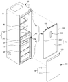
- a refrigerator includes a main body 10, a storage compartment 20 which is provided inside the main body 10 such that a front surface thereof is open and door assemblies 100 and 200 which is rotatably coupled to the main body 10 to open and close the open front surface of the storage compartment 20.
- the main body 10 includes an internal structure 11 which forms the storage compartment 20, an external structure 13 which is coupled to an outside of the internal structure 11 and forms an exterior, and a cooling air supplying device (not shown) which supplies cooling air to the storage compartment 20.
- the cooling air supplying device may include a compressor, a condenser, an expansion valve, an evaporator, a fan, a cool air duct and so on, and an insulation material (not shown) is filled between the internal structure 11 and the external structure 13 to prevent the cool air in the storage compartment 20 from leaking.
- a mechanical compartment (not shown) in which the compressor and the condenser compressing a refrigerant and condensing the compressed refrigerant respectively are installed may be provided at a lower side of a rear of the main body 10.
- the storage compartment 20 may be divided into a refrigerator compartment 21 as an upper storage compartment and a freezer compartment 23 as a lower storage compartment by a partition wall 15, and a plurality of shelves 25 on which food or the like is stacked and stored may be provided therein and divide an inside of the refrigerator compartment 21 or the freezer compartment 23 into a plurality of areas.
- a storage container 27 which accommodates and stores the food or the like may be provided inside the storage compartment 20.
- the storage compartment 20 may be opened and closed by the door assemblies 100 and 200 which are rotatably coupled to the main body 10, and a plurality of door guards 203 which store the food or the like may be installed at a rear surface of the door assembly 200.
- Each of the door assemblies 100 and 200 may be rotatably coupled to the main body 10 by a hinge unit 40, and the hinge unit 40 may include an upper hinge 41, a middle hinge 43 and a lower hinge 45.
- a gasket 400 which maintains an airtight state between the main body 10 and the door assemblies 100 and 200 and prevents the cool air in the storage compartment 20 from leaking to an outside while the door assemblies 100 and 200 are closed is provided at a rear surface of each of the door assemblies 100 and 200.
- the door assemblies 100 and 200 include a freezer compartment door assembly 100 which opens and closes the freezer compartment 23 which is the lower storage compartment, and a refrigerator compartment door assembly 200 which opens and closes the refrigerator compartment 21 which is the upper storage compartment.
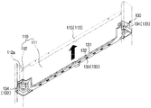
- the freezer compartment door assembly 100 which opens and closes the freezer compartment 23 includes a door plate 110 which forms a front surface and side surfaces of the freezer compartment door assembly 100, a door cap 120 which covers an upper portion of the door plate 110, and a door cap supporting part 130 which is fixed to the door plate 110 so that the door cap 120 is provided at the upper portion of the door plate 110 and supports the door cap 120.
- the door plate 110 includes a front plate 111 which forms a front surface of the freezer compartment door assembly 100 and side plates 112 which are provided to be bent backward from both sides of the front plate 111 and form the side surfaces of the freezer compartment door assembly 100.
- a rear plate 117 is coupled to a rear surface of the door plate 110 and forms a rear surface of the freezer compartment door assembly 100.
- a bent portion 113 and fixing holes 112a to which the door cap supporting part 130 is fixed are provided at an upper end of each of the front plate 111 and the side plates 112.
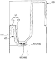
- the bent portion 113 includes a first bent portion 114 which is formed backward at the upper end of the front plate 111 to be bent vertically to the front plate 111 and a second bent portion 115 which is formed downward at an end of the first bent portion 114 to be bent vertically to the first bent portion 114.
- a fixing groove 116 which is opened downward is provided between the front plate 111 and the second bent portion 115, and the door cap supporting part 130 is inserted into the fixing groove 116 from a lower side of the fixing groove 116 toward an upper side thereof and fixed to the fixing groove 116.
- the door cap 120 is not directly coupled to the door plate 110 but is coupled to the door cap supporting part 130 fixed to the upper portion of the door plate 110 and covers the upper portion of the door plate 110.
- the door cap supporting part 130 includes an inserting portion 131 which is inserted into the fixing groove 116, a plurality of protruding ribs 132 which are provided to protrude from a rear surface of the inserting portion 131, and a coupling portion 133 to which the door cap 120 is coupled.
- the inserting portion 131 of the cap supporting part 130 When the inserting portion 131 of the cap supporting part 130 is inserted into the fixing groove 116, the plurality of protruding ribs 132 provided at the inserting portion 131 are in close contact with the second bent portion 115, and thus the door cap supporting part 130 is fixed to the door plate 110.
- the drawings have illustrated an example in which the protruding ribs 132 are provided at the rear surface of the inserting portion 131 to be in close contact with the second bent portion 115, however, the protruding ribs 132 may be provided at a front surface of the inserting portion 131 to be in close contact with the front plate 111 of the door plate 110.
- a fixing protrusion 136 which is fixed to the fixing holes 112a of the side plates 112 when the inserting portion 131 is fixed to the fixing groove 116 may be provided at the door cap supporting part 130.
- a plurality of coupling portions 133 to which the door cap 120 is fixed are provided and includes a coupling protrusion 134 which is provided at a position corresponding to a first coupling hook 125 of the door cap 120 which will be described below and to which the first coupling hook 125 is coupled and a coupling hole 135 which is provided at a position corresponding to a second coupling hook 127 and to which the second coupling hook 127 is coupled.
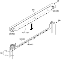
- the door cap 120 includes a recessed portion 121 which covers the upper portion of the door plate 110 and is recessed downward to provide a gripping groove 101 between the door plate 110 and the bent portion 113 and a plurality of coupling hooks 123 which are coupled to the door cap supporting part 130.
- the gripping groove 101 is provided between the recessed portion 121 of the door cap 120 and the bent portion 113 of the door plate 110, and the gripping groove 101 serves as a handle which is gripped by a user to open and close the freezer compartment door assembly 100.
- the user when the user opens and closes the freezer compartment door assembly 100, the user inserts his/her hand into the gripping groove 101, grips the bent portion 113, and then opens and closes the freezer compartment door assembly 100.
- the coupling hooks 123 include a first coupling hook 125 which is provided at each of both sides of the door cap 120 and a plurality of second coupling hooks 127 which are provided at a lower portion of the recessed portion 121.
- the first coupling hook 125 is coupled to the coupling protrusion 134 of the door cap supporting part 130
- the second coupling hooks 127 are coupled to the coupling holes 135 of the door cap supporting part 130.
- the coupling holes 135 of the door cap supporting part 130 are provided at a rear of the inserting portion 131 inserted into the fixing groove 116, and thus a portion at which the second coupling hook 127 of the door cap 120 is coupled to the coupling hole 135 of the door cap supporting part 130 is covered by the door plate 110 and is not exposed to a front surface when the door cap 120 is coupled to the door cap supporting part 130.
- the external appearance becomes simplified and may result in a good design and also foreign substances may be prevented from entering through a gap of the portion at which the door cap 120 is coupled to the door cap supporting part 130.
- a hinge hole 129 in which a hinge shaft 43a of the middle hinge 43 is rotatably inserted may be provided at each of both ends of the door cap 120, and a hinge groove 137 in which the hinge shaft 43a is rotatably inserted may be provided at each of both ends of the door cap supporting part 130.
- the drawings have illustrated an example in which the middle hinge 43 is provided at a right side of the main body 10.
- the hinge hole 129 and the hinge groove 137 are provided at both ends of each of the door cap 120 and the door cap supporting part 130, the freezer compartment door assembly 100 may be applied regardless of a position at which the middle hinge 43 is provided.
- the door cap supporting part 130 is moved from a lower side toward an upper side, and the inserting portion 131 is inserted into the fixing groove 116 which is opened downward, and the plurality of protruding ribs 132 which are provided at the rear surface of the inserting portion 131 to protrude are in close contact with the second bent portion 115 so that the door cap supporting part 130 is fixed to the door plate 110.
- the inserting portion 131 is inserted into the fixing groove 116, the fixing protrusions 136 provided at both sides of the door cap supporting part 130 are inserted into the fixing holes 112a provided at the side plates 112, and thus the door cap supporting part 130 is fixed to the door plate 110.
- the door cap 120 When the door cap supporting part 130 is fixed to the door plate 110, the door cap 120 is moved from the upper side toward the lower side, and thus the door cap 120 is coupled to the door cap supporting part 130.
- the door cap 120 enables the first coupling hook 125 and the second coupling hooks 127 provided at the door cap 120 to correspond to the coupling protrusion 134 and the coupling holes 135 and thus is coupled to the door cap supporting part 130.
- the second coupling hooks 127 of the door cap 120 are inserted into and coupled to the coupling holes 135 of the door cap supporting part 130.
- the first coupling hook 125 of the door cap 120 is coupled to the coupling protrusion 134 of the door cap supporting part 130.
- the refrigerator compartment door assembly 200 which opens and closes the refrigerator compartment 21 includes a door plate 210 which forms a front surface and side surfaces of the refrigerator compartment door assembly 200 and a door cap 220 which covers an upper portion of the door plate 210.
- the door plate 210 includes a front plate 211 which forms a front surface of the refrigerator compartment door assembly 200 and side plates 212 which are provided to be bent backward from both sides of the front plate 211 and form the side surfaces of the refrigerator compartment door assembly 200.
- a rear plate 219 (referring to FIG. 16 ) is coupled to a rear surface of the door plate 210 and forms a rear surface of the refrigerator compartment door assembly 200.
- a bent portion 213 to which the door cap 220 is fixed is provided at an upper end of the front plate 211.
- the bent portion 213 includes a first bent portion 214 which is formed backward at the upper end of the front plate 211 to be bent vertically to the front plate 211 and a second bent portion 215 which is formed downward at an end of the first bent portion 214 to be bent vertically to the first bent portion 214.
- a fixing groove 218 which is opened downward is provided between the front plate 211 and the second bent portion 215, and the door cap 220 is inserted into the fixing groove 218 from a lower side of the fixing groove 218 toward an upper side thereof and fixed to the fixing groove 218.
- a first coupling hole 216 and a second coupling hole 217 to which the door cap 220 is coupled are provided at the second bent portion 215 and the side plates 212, respectively.
- the door cap 220 includes an inserting portion 221 which covers an upper portion of the door plate 210 and is inserted into the fixing groove 218 and a first coupling protrusion 223 and a second coupling protrusion 225 which are coupled to the door plate 210.
- the first coupling protrusion 223 and the second coupling protrusion 225 of the door cap 220 are provided at positions corresponding to the first coupling hole 216 and the second coupling hole 217 of the door plate 210 when the inserting portion 221 is fixed to the fixing groove 218.
- the inserting portion 221 of the door cap 220 is inserted into the fixing groove 218, the first coupling protrusion 223 is coupled to the first coupling hole 216, and the second coupling protrusion 225 is inserted into the second coupling hole 217.
- first coupling protrusion 223 and the first coupling hole 216 for coupling between the front plate 211 of the door plate 210 and the door cap 220 are located at a rear of the bent portion 213, a portion at which the first coupling protrusion 223 and the first coupling hole 216 are coupled to each other is not exposed to a front surface of the refrigerator compartment door assembly 200 when the door cap 220 is coupled to the door plate 210.
- the portion at which the door plate 210 and the door cap 220 are coupled to each other is not exposed to the front surface of the refrigerator, the external appearance becomes simplified and may result in a good design, and also foreign substances may be prevented from entering through a gap of the portion at which the door plate 210 and the door cap 220 are coupled to each other.
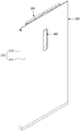
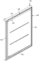
- a display unit 300 is provided at the refrigerator compartment door assembly 200.
- the refrigerator compartment door assembly 200 includes the door plate 210 which forms the front surface and the side surfaces of the refrigerator compartment door assembly 200, and the rear plate 219 which forms the rear surface of the refrigerator compartment door assembly 200.
- An insulation material U is filled between the door plate 210 and the rear plate 219 (Referring to FIGS. 22 and 23 ).
- An opening 230 through which a front surface of the display unit 300 is exposed to an outside is provided at a front surface of the door plate 210.
- a coupling portion 240 which is bent downward toward an inside of the door plate 210 and to which a display installation part 310 and a displaying part 320 which will be described below are coupled is provided at an edge of the opening 230.
- the display unit 300 may display operation information of the refrigerator or may receive an operation command of the refrigerator.
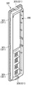
- the display unit 300 includes the display installation part 310 at which a display 311 is installed, the displaying part 320 which is disposed at a front surface of the display installation part 310 to indicate the operation information displayed on the display 311 to an outside, and a sealing member 330 which seals between the display installation part 310 and the displaying part 320 to prevent moisture from penetrating into the display unit 300.
- the display installation part 310 is provided inside the refrigerator door assembly 200 to correspond to the opening 230 provided at the front surface of the door plate 210.
- the display installation part 310 includes a plurality of coupling ribs 313 which are coupled to the coupling portion 240 provided at the edge of the opening 230 to be bent, a close contact portion 315 which is in close contact with the rear surface of the door plate 210 to prevent the insulation material U from penetrating into the display installation part 310, and a protruding rib 317 which is provided to correspond to a seating groove 327 of the displaying part 320 which will be described below.
- the plurality of coupling ribs 313 are provided at both sides of the display installation part 310, and a plurality of first coupling holes 241 to which the plurality of coupling ribs 313 are coupled are provided at both sides of the coupling portion 240.
- the close contact portion 315 is in close contact with a rear surface of the front plate 211 of the door plate 210 when the display installation part 310 is coupled to the coupling portion 240 and prevents the insulation material U filled in the refrigerator door assembly 200 from penetrating into the display installation part 310.
- the displaying part 320 is disposed at the front surface of the display installation part 310 and exposed to the outside through the opening 230 provided at the front surface of the door plate 210.
- the front surface of the displaying part 320 exposed to the outside through the opening 230 may be formed of a transparent material which enables the operation information displayed on the display 311 to be recognized from the outside.
- the displaying part 320 includes a plurality of coupling hooks 321 which are coupled to the coupling portion 240, and the seating groove 327 in which the sealing member 330 is seated.
- the coupling hooks 321 includes a first coupling hook 323 which is provided at each of upper and lower portions of the displaying part 320, and a plurality of second coupling hook 325 which are provided at both side surfaces of the displaying part 320.
- the first coupling hook 323 is coupled to the upper and lower portions of the coupling portion 240, and a plurality of second coupling holes 243 to which the second coupling hooks 325 are coupled are provided at both side surfaces of the coupling portion 240.
- the plurality of first coupling holes 241 to which the coupling ribs 313 of the display installation part 310 are coupled and the plurality of second coupling holes 243 to which the second coupling hooks 325 of the displaying part 320 are coupled are provided at both side surfaces of the coupling portion 240.
- the second coupling holes 243 are located between the first coupling holes 241, and the first coupling holes 241 are located between the second coupling holes 243.
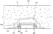
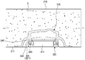
- FIG. 22 is a cross-sectional view of a portion at which the coupling rib 313 of the display installation part 310 is coupled to the first coupling hole 241, and FIG.
- FIG. 23 is a cross-sectional view of a portion at which the second coupling hook 325 of the displaying part 320 is coupled to the second coupling hole 243)
- the sealing member 330 Since the sealing member 330 is pressed by the protruding rib 317 and the seating groove 327, the display installation part 310 and displaying part 320 are in close contact with each other by the sealing member 330, and thus moisture is prevented from penetrating into the display unit 300.
- a temperature of the front surface of the refrigerator compartment door assembly 200 which is in contact with the outside of the refrigerator compartment 21 becomes lower than that of the outside through a heat exchange.
- the temperature is referred to as the dew-point temperature.
- a portion of the front surface of the refrigerator compartment door assembly 200 at which the display unit 300 is provided has the insulation material U which is thinner than other portions, and thus when the temperature of the front surface of the refrigerator compartment door assembly 200 is lowered and reaches the dew-point temperature, moisture is condensed and forms the dews on the front surface of the refrigerator compartment door assembly 200.
- the dew Since the displaying part 320 is exposed to the front surface of the refrigerator compartment door assembly 200, the dew would penetrate into the display unit 300 when the dew is formed on the front surface of the refrigerator compartment door assembly 200, however, since the sealing member 330 seals between the display installation part 310 and the displaying part 320, the moisture is prevented from penetrating into the display unit 300, and thus an electrical damage or a malfunction of the display 311 due to penetration of the moisture into the display unit 300 may be prevented.
- the overall humidity of the display unit 300 is lowered.
- the humidity of the displaying part 320 is lowered when the overall humidity of the display unit 300 is lowered, and thus the dew formation occurring on the displaying part 320 may be minimized.
- the gasket 400 which maintains an airtightness between the main body 10 and the door assemblies 100 and 200 when the door assemblies 100 and 200 are closed is coupled to a rear surface of each of the door assemblies 100 and 200.
- the gasket 400 is integrally injection-molded, and coupled to the rear surface of the freezer compartment door assembly 100.
- the gasket 400 maintains the airtightness between the main body 10 and the freezer compartment door assembly 100, and thus prevents the cool air in the freezer compartment 23 from leaking to an outside.
- the gasket 400 includes an upper gasket 401 which is coupled to an upper portion of the rear surface of the freezer compartment door assembly 100, a lower gasket 403 which is coupled to a lower portion of the rear surface of the freezer compartment door assembly 100, a left gasket 405 which is coupled to a left side of the rear surface of the freezer compartment door assembly 100, and a right gasket 407 which is coupled to a right side of the rear surface of the freezer compartment door assembly 100.
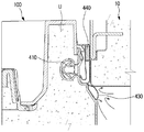
- each of the gaskets 400 includes a coupling portion 410 which is coupled to the rear surface of the freezer compartment door assembly 100, a close contact portion 420 which is in close contact with the main body 10 when the freezer compartment door assembly 100 is closed and maintains the airtightness between the main body 10 and the freezer compartment door assembly 100, and a cool air leakage preventing portion 430 which extends from one side of the close contact portion 420 toward the freezer compartment 23 and prevents the cool air from leaking through a gap between the main body 10 and the freezer compartment door assembly 100.
- a coupling groove 105 to which the gasket 400 is coupled is provided at the rear surface of the freezer compartment door assembly 100, and the coupling portion 410 of the gasket 400 is coupled to the coupling groove 105.
- the close contact portion 420 includes a contact portion 421 which is in contact with the main body 10 when the freezer compartment door assembly 100 is closed, a shock absorbing portion 423 which absorbs a shock generated between the main body 10 and the freezer compartment door assembly 100 when the freezer compartment door assembly 100 is closed, and a magnet accommodation portion 425 which accommodates a magnet 440 so that the freezer compartment door assembly 100 is in close contact with the main body 10.
- the cool air leakage preventing portion 430 is provided to have a length shorter than that of the close contact portion 420, and prevents the cool air in the freezer compartment 34 from leaking through the gap between the main body 10 and the freezer compartment door assembly 100.
- the close contact portion 420 prevents the cool air in the freezer compartment 34 from leaking through the gap between the main body 10 and the freezer compartment door assembly 100.
- the cool air leakage preventing portion 430 which extends from the close contact portion 420 doubly seals between the main body 10 and the freezer compartment door assembly 100, the leakage of the cool air in the freezer compartment 34 through the gap between the main body 10 and the freezer compartment door assembly 100 may be minimized.
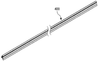
- the gasket 400 is integrally formed by an extrusion molding to make up the coupling portion 410, the close contact portion 420 and the cool air leakage preventing portion 430.
- the integrally extruded gasket 400 is cut to a length corresponding to each length of upper and lower edges and left and right edges of the rear surface of the freezer compartment door assembly 100.
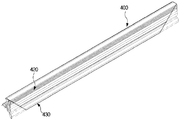
- both ends of each of the cut gaskets 400 are cut at an angle of 45 degrees to be bonded in a quadrangular shape corresponding to the edges of the rear surface of the freezer compartment door assembly 100, as illustrated in FIG. 31 .
- a cut length of the cool air leakage preventing portion 430 may be about 30 mm.
- Each of the gaskets 400 of which both ends are cut at the angle of 45 degrees is bonded by thermal bonding to result in the quadrangular shape corresponding to the edges of the rear surface of the freezer compartment door assembly 100.
- thermal bonding it is not easy to bond cross sections of the gasket 400 including all of the coupling portion 410, the close contact portion 420 and the cool air leakage preventing portion 430. Therefore, when a part of both ends of the cool air leakage preventing portion 430 is cut, and each gasket 400 is bonded by the thermal bonding, only the coupling portion 410 and the close contact portion 420 are provided to be bonded by the thermal bonding.
- the magnet 440 is inserted into the magnet accommodation portion 425 of the close contact portion 420, as illustrated in FIG. 33 .
- each of the gaskets 400 is bonded by the thermal bonding to form the quadrangular shape and then coupled to the rear surface of the freezer compartment door assembly 100.
- the moisture penetration into the display unit can be prevented, and the generation of the moisture on the front surface of the display unit can be prevented or minimized, while insulation thickness of the portion of the refrigerator compartment door at which the display unit is provided can be thin.
Landscapes
- Engineering & Computer Science (AREA)
- Chemical & Material Sciences (AREA)
- Combustion & Propulsion (AREA)
- Physics & Mathematics (AREA)
- Mechanical Engineering (AREA)
- Thermal Sciences (AREA)
- General Engineering & Computer Science (AREA)
- Refrigerator Housings (AREA)
- Cold Air Circulating Systems And Constructional Details In Refrigerators (AREA)
Claims (8)
- Kühlschrank, der Folgendes umfasst:einen Hauptkörper (10);einen Aufbewahrungsbereich (20), der innerhalb des Hauptkörpers (10) bereitgestellt ist, sodass eine Vorderfläche davon geöffnet ist;eine Türbaugruppe (100, 200), die mit dem Hauptkörper (10) drehbar gekoppelt ist, um die geöffnete Vorderfläche des Aufbewahrungsbereichs (20) zu öffnen und schließen, und eine Öffnung (230) aufweist, die an einer Vorderfläche davon bereitgestellt ist; undeine Anzeigeeinheit (300), die auf der Türbaugruppe (100, 200) bereitgestellt ist,wobei die Anzeigeeinheit (300) Folgendes umfasst:ein Anzeigeinstallationsteil (310), das innerhalb der Türbaugruppe (100, 200) so bereitgestellt ist, das es der Öffnung (230) entspricht, und an dem eine Anzeige (311) installiert ist,ein Anzeigeteil (320), das an einer Vorderfläche des Anzeigeinstallationsteils (310) angeordnet ist und gegenüber einer Außenseite über die Öffnung (230) exponiert ist,ein Dichtungsglied (330), das zwischen dem Anzeigeinstallationsteil (310) und dem Anzeigeteil (320) dichtet und verhindert, dass Feuchtigkeit in die Anzeigeeinheit (300) eindringt, dadurch gekennzeichnet, dass die Anzeigeeinheit ferner Folgendes umfasst:einen Kopplungsabschnitt (240),eine Sitznut (327), in der das Dichtungsglied (330) sitzt, undeine vorstehende Rippe (317), die der Sitznut (327) entspricht und an dem Anzeigeinstallationsteil (310) bereitgestellt ist, wobeiwenn das Anzeigeinstallationsteil (310) und das Anzeigeteil (320) mit dem Kopplungsabschnitt (240) gekoppelt sind, die vorstehende Rippe (317) das Dichtungsglied (330) presst, während es in der Sitznut (327) eingelegt ist, und das Dichtungsglied (330) zwischen der vorstehenden Rippe (317) und der Sitznut (327) dichtet.
- Kühlschrank gemäß Anspruch 1, wobei die Türbaugruppe (100, 200) eine Türplatte (110, 210), die eine Vorderfläche und Seitenflächen der Türplatte bildet, und eine Rückplatte (117, 219), die eine Rückfläche der Türplatte bildet, umfasst und ein Isolationsmaterial zwischen der Türplatte (110, 210) und der Rückplatte (117, 219) gefüllt ist.
- Kühlschrank gemäß Anspruch 2, wobei die Öffnung (230) an einer Vorderfläche der Türplatte (110, 210) bereitgestellt ist und der Kopplungsabschnitt (240), der zu einer Innenseite der Türplatte (110, 210) hin gebogen ist und mit dem das Anzeigeinstallationsteil (310) und das Anzeigeteil (320) gekoppelt sind, an einem Rand der Öffnung (230) bereitgestellt ist.
- Kühlschrank gemäß Anspruch 3, wobei das Anzeigeinstallationsteil (310) eine Vielzahl von Kopplungsrippen (313), die mit dem Kopplungsabschnitt (240) gekoppelt ist, und einen Dichtkontaktabschnitt (315), der mit einer Rückfläche der Türplatte (110, 210) in Dichtkontakt steht und verhindert, dass das Isolationsmaterial in das Anzeigeinstallationsteil (310) eindringt, umfasst.
- Kühlschrank gemäß Anspruch 4, wobei die Vielzahl von Kopplungsrippen (313) an beiden Seiten des Anzeigeinstallationsteils (310) bereitgestellt ist und eine Vielzahl von ersten Kopplungslöchern (241), mit der die Vielzahl von Kopplungsrippen (313) gekoppelt ist, an beiden Seitenflächen des Kopplungsabschnitts (240) bereitgestellt ist.
- Kühlschrank gemäß Anspruch 5, wobei das Anzeigeteil (320) eine Vielzahl von Kopplungshaken (321) umfasst, die mit dem Kopplungsabschnitt (240) gekoppelt ist.
- Kühlschrank gemäß Anspruch 6, wobei die Vielzahl von Kopplungshaken (321) einen ersten Kopplungshaken (323), der an jedem eines oberen und unteren Abschnitts des Anzeigeteils (320) bereitgestellt ist, und eine Vielzahl von zweiten Kopplungshaken (325), die an beiden Seitenflächen des Anzeigeteils (320) bereitgestellt ist, umfasst.
- Kühlschrank gemäß Anspruch 7, wobei der erste Kopplungshaken (323) mit dem oberen und unteren Abschnitt des Kopplungsabschnitts (240) gekoppelt ist und eine Vielzahl von zweiten Kopplungslöchern (243), mit der die zweiten Kopplungshaken (325) gekoppelt sind, an beiden Seitenflächen des Kopplungsabschnitts (240) bereitgestellt ist.
Applications Claiming Priority (1)
| Application Number | Priority Date | Filing Date | Title |
|---|---|---|---|
| KR1020150000408A KR20160084020A (ko) | 2015-01-05 | 2015-01-05 | 냉장고 및 냉장고의 디스플레이 유닛 |
Publications (2)
| Publication Number | Publication Date |
|---|---|
| EP3040662A1 EP3040662A1 (de) | 2016-07-06 |
| EP3040662B1 true EP3040662B1 (de) | 2021-04-28 |
Family
ID=55027609
Family Applications (1)
| Application Number | Title | Priority Date | Filing Date |
|---|---|---|---|
| EP15203185.2A Active EP3040662B1 (de) | 2015-01-05 | 2015-12-30 | Kühlschrank und anzeigeeinheit für kühlschrank |
Country Status (4)
| Country | Link |
|---|---|
| US (1) | US9702621B2 (de) |
| EP (1) | EP3040662B1 (de) |
| KR (1) | KR20160084020A (de) |
| CN (1) | CN105806036B (de) |
Families Citing this family (55)
| Publication number | Priority date | Publication date | Assignee | Title |
|---|---|---|---|---|
| US9221210B2 (en) | 2012-04-11 | 2015-12-29 | Whirlpool Corporation | Method to create vacuum insulated cabinets for refrigerators |
| US8986483B2 (en) | 2012-04-02 | 2015-03-24 | Whirlpool Corporation | Method of making a folded vacuum insulated structure |
| US10052819B2 (en) | 2014-02-24 | 2018-08-21 | Whirlpool Corporation | Vacuum packaged 3D vacuum insulated door structure and method therefor using a tooling fixture |
| US9689604B2 (en) | 2014-02-24 | 2017-06-27 | Whirlpool Corporation | Multi-section core vacuum insulation panels with hybrid barrier film envelope |
| KR101998569B1 (ko) * | 2015-01-05 | 2019-09-27 | 삼성전자주식회사 | 냉장고 및 냉장고의 도어 어셈블리 |
| US9476633B2 (en) | 2015-03-02 | 2016-10-25 | Whirlpool Corporation | 3D vacuum panel and a folding approach to create the 3D vacuum panel from a 2D vacuum panel of non-uniform thickness |
| US10161669B2 (en) | 2015-03-05 | 2018-12-25 | Whirlpool Corporation | Attachment arrangement for vacuum insulated door |
| US9897370B2 (en) | 2015-03-11 | 2018-02-20 | Whirlpool Corporation | Self-contained pantry box system for insertion into an appliance |
| US9441779B1 (en) | 2015-07-01 | 2016-09-13 | Whirlpool Corporation | Split hybrid insulation structure for an appliance |
| US11052579B2 (en) | 2015-12-08 | 2021-07-06 | Whirlpool Corporation | Method for preparing a densified insulation material for use in appliance insulated structure |
| US12508751B2 (en) | 2015-12-08 | 2025-12-30 | Whirlpool Corporation | Insulation compaction device and method for forming an insulated structure for an appliance |
| US10429125B2 (en) | 2015-12-08 | 2019-10-01 | Whirlpool Corporation | Insulation structure for an appliance having a uniformly mixed multi-component insulation material, and a method for even distribution of material combinations therein |
| US10041724B2 (en) | 2015-12-08 | 2018-08-07 | Whirlpool Corporation | Methods for dispensing and compacting insulation materials into a vacuum sealed structure |
| US10422573B2 (en) | 2015-12-08 | 2019-09-24 | Whirlpool Corporation | Insulation structure for an appliance having a uniformly mixed multi-component insulation material, and a method for even distribution of material combinations therein |
| US10222116B2 (en) | 2015-12-08 | 2019-03-05 | Whirlpool Corporation | Method and apparatus for forming a vacuum insulated structure for an appliance having a pressing mechanism incorporated within an insulation delivery system |
| US11994336B2 (en) | 2015-12-09 | 2024-05-28 | Whirlpool Corporation | Vacuum insulated structure with thermal bridge breaker with heat loop |
| EP3387351B1 (de) | 2015-12-09 | 2021-10-13 | Whirlpool Corporation | Vakuumisolationskonstruktionen mit mehreren isolatoren |
| US10422569B2 (en) | 2015-12-21 | 2019-09-24 | Whirlpool Corporation | Vacuum insulated door construction |
| US10018406B2 (en) | 2015-12-28 | 2018-07-10 | Whirlpool Corporation | Multi-layer gas barrier materials for vacuum insulated structure |
| US10610985B2 (en) | 2015-12-28 | 2020-04-07 | Whirlpool Corporation | Multilayer barrier materials with PVD or plasma coating for vacuum insulated structure |
| US10807298B2 (en) | 2015-12-29 | 2020-10-20 | Whirlpool Corporation | Molded gas barrier parts for vacuum insulated structure |
| US10030905B2 (en) | 2015-12-29 | 2018-07-24 | Whirlpool Corporation | Method of fabricating a vacuum insulated appliance structure |
| US11247369B2 (en) | 2015-12-30 | 2022-02-15 | Whirlpool Corporation | Method of fabricating 3D vacuum insulated refrigerator structure having core material |
| EP3443285B1 (de) | 2016-04-15 | 2021-03-10 | Whirlpool Corporation | Vakuumisolierter kühlschrank |
| US11009284B2 (en) | 2016-04-15 | 2021-05-18 | Whirlpool Corporation | Vacuum insulated refrigerator structure with three dimensional characteristics |
| US11320193B2 (en) | 2016-07-26 | 2022-05-03 | Whirlpool Corporation | Vacuum insulated structure trim breaker |
| KR101845999B1 (ko) * | 2016-07-28 | 2018-04-06 | 삼성전자주식회사 | 냉장고 |
| WO2018034665A1 (en) | 2016-08-18 | 2018-02-22 | Whirlpool Corporation | Machine compartment for a vacuum insulated structure |
| KR102687627B1 (ko) | 2016-08-29 | 2024-07-23 | 엘지전자 주식회사 | 냉장고 |
| US10281191B2 (en) * | 2016-11-23 | 2019-05-07 | Bsh Hausgeraete Gmbh | Home appliance door |
| US10281195B2 (en) * | 2016-11-28 | 2019-05-07 | Bsh Hausgeraete Gmbh | Home appliance device |
| US10598424B2 (en) | 2016-12-02 | 2020-03-24 | Whirlpool Corporation | Hinge support assembly |
| US10352613B2 (en) | 2016-12-05 | 2019-07-16 | Whirlpool Corporation | Pigmented monolayer liner for appliances and methods of making the same |
| CN106839639B (zh) * | 2016-12-27 | 2021-04-16 | 青岛海尔特种电冰柜有限公司 | 冷柜温显仪和冷柜 |
| CN106802059B (zh) * | 2016-12-27 | 2020-12-15 | 青岛海尔特种电冰柜有限公司 | 冷柜温显仪的下盖和冷柜温显仪 |
| US10317128B2 (en) * | 2017-01-03 | 2019-06-11 | Samsung Electronics Co., Ltd. | Refrigerator |
| US10907888B2 (en) | 2018-06-25 | 2021-02-02 | Whirlpool Corporation | Hybrid pigmented hot stitched color liner system |
| EP3899386B1 (de) * | 2018-12-21 | 2023-06-07 | Electrolux Appliances Aktiebolag | Haushaltsgerät mit umkehrbarer tür |
| CN109780800B (zh) * | 2019-01-04 | 2023-03-31 | 海尔智家股份有限公司 | 具有显示屏组件的门中门及具有其的冰箱 |
| US10907891B2 (en) | 2019-02-18 | 2021-02-02 | Whirlpool Corporation | Trim breaker for a structural cabinet that incorporates a structural glass contact surface |
| WO2020213861A1 (en) | 2019-04-15 | 2020-10-22 | Samsung Electronics Co., Ltd. | Refrigerator |
| KR102312667B1 (ko) * | 2019-04-15 | 2021-10-15 | 삼성전자주식회사 | 냉장고 |
| AU2020327341B2 (en) * | 2019-08-20 | 2022-09-22 | Samsung Electronics Co., Ltd. | Refrigerator and home appliance |
| KR102846286B1 (ko) * | 2020-01-17 | 2025-08-13 | 일렉트로룩스 두 브라질 에스/에이 | 냉장 기기의 도어를 위한 엔드캡 조립체 |
| KR102950634B1 (ko) * | 2020-04-08 | 2026-04-09 | 삼성전자주식회사 | 냉장고 |
| US11796243B2 (en) * | 2020-06-17 | 2023-10-24 | Lg Electronics Inc. | Refrigerator |
| KR20210156172A (ko) * | 2020-06-17 | 2021-12-24 | 엘지전자 주식회사 | 냉장고 |
| CN113865231B (zh) * | 2020-06-30 | 2023-07-14 | 青岛海尔电冰箱有限公司 | 可更换门面的冰箱门 |
| US12070924B2 (en) | 2020-07-27 | 2024-08-27 | Whirlpool Corporation | Appliance liner having natural fibers |
| WO2022108122A1 (ko) * | 2020-11-18 | 2022-05-27 | 삼성전자주식회사 | 냉장고 |
| KR102486948B1 (ko) * | 2020-12-16 | 2023-01-10 | 엘지전자 주식회사 | 냉장고 |
| DE102021202364A1 (de) * | 2021-03-11 | 2022-09-15 | BSH Hausgeräte GmbH | Hinterlegteil für ein Haushaltskältegerätbauteil, Anordnung mit einem Haushaltskältegerätbauteil und einem Hinterlegteil, sowie Montageverfahren |
| EP4367452B1 (de) * | 2021-07-08 | 2026-02-04 | Vestel Beyaz Esya Sanayi ve Ticaret Anonim Sirketi | Weissgerät mit einem drahtlosverbindungsmodul |
| US20240035731A1 (en) * | 2022-07-29 | 2024-02-01 | Fisher & Paykel Appliances Limited | Trim attachment system for appliance |
| TR2022013473A2 (tr) * | 2022-08-26 | 2024-01-22 | Bsh Ev Aletleri Sanayi Ve Ticaret Anonim Sirketi | Bi̇r tutamak oyuğuna sahi̇p bi̇r soğutucu ci̇haz |
Family Cites Families (13)
| Publication number | Priority date | Publication date | Assignee | Title |
|---|---|---|---|---|
| US4966004A (en) * | 1989-11-06 | 1990-10-30 | Amana Refrigeration, Inc. | Electronic control mounting apparatus for refrigerator |
| JPH09203949A (ja) * | 1996-01-29 | 1997-08-05 | Minolta Co Ltd | 防水カメラ |
| KR20010037542A (ko) | 1999-10-18 | 2001-05-15 | 구자홍 | 냉장고의 디스플레이부 장착구조 |
| JP2002031471A (ja) * | 2000-07-19 | 2002-01-31 | Matsushita Refrig Co Ltd | 冷蔵庫の扉 |
| JP2004347238A (ja) | 2003-05-22 | 2004-12-09 | Toshiba Corp | 冷蔵庫 |
| US20060261220A1 (en) * | 2005-05-19 | 2006-11-23 | Samsung Electronics Co., Ltd. | Storage compartment with display support |
| BRPI0613196B1 (pt) * | 2005-07-20 | 2020-11-10 | Lg Electronics Inc. | porta de refrigerador |
| WO2010029042A1 (en) * | 2008-09-09 | 2010-03-18 | Arcelik Anonim Sirketi | A household appliance |
| KR20110009436A (ko) * | 2009-07-22 | 2011-01-28 | 엘지전자 주식회사 | 냉장고 |
| US9069201B2 (en) * | 2010-03-19 | 2015-06-30 | Balboa Wter Group, Inc. | Waterproof user interface display panels |
| KR101338556B1 (ko) | 2012-08-09 | 2013-12-06 | 현대모비스 주식회사 | 차량용 헤드램프의 습기발생 방지 구조 |
| US8960934B2 (en) * | 2013-04-08 | 2015-02-24 | Samsung Electronics Co., Ltd. | Refrigerator and method of manufacturing the same |
| KR102220809B1 (ko) * | 2013-08-22 | 2021-02-26 | 삼성전자주식회사 | 냉장고 |
-
2015
- 2015-01-05 KR KR1020150000408A patent/KR20160084020A/ko not_active Ceased
- 2015-12-30 EP EP15203185.2A patent/EP3040662B1/de active Active
-
2016
- 2016-01-05 US US14/988,652 patent/US9702621B2/en active Active
- 2016-01-05 CN CN201610119166.4A patent/CN105806036B/zh active Active
Non-Patent Citations (1)
| Title |
|---|
| None * |
Also Published As
| Publication number | Publication date |
|---|---|
| EP3040662A1 (de) | 2016-07-06 |
| KR20160084020A (ko) | 2016-07-13 |
| US9702621B2 (en) | 2017-07-11 |
| US20160209110A1 (en) | 2016-07-21 |
| CN105806036B (zh) | 2018-09-11 |
| CN105806036A (zh) | 2016-07-27 |
Similar Documents
| Publication | Publication Date | Title |
|---|---|---|
| EP3040662A1 (de) | Kühlschrank und anzeigeeinheit für kühlschrank | |
| EP3244147B1 (de) | Kühlschrank | |
| KR102186861B1 (ko) | 냉장고 | |
| CN101846430B (zh) | 冰箱 | |
| TWI392841B (zh) | refrigerator | |
| JP6005341B2 (ja) | 冷蔵庫 | |
| JP5753379B2 (ja) | 冷却貯蔵庫の扉装置 | |
| KR20140060431A (ko) | 냉장고 및 그 내부 도어의 제조 방법 | |
| KR20140060429A (ko) | 냉장고 및 그 내부 도어의 제조 방법 | |
| US11598570B2 (en) | Refrigerator including a heater | |
| KR20140060145A (ko) | 냉장고 및 그 내부 도어의 제조 방법 | |
| TR201909656T4 (tr) | Buzdolabı. | |
| US10627152B2 (en) | Domestic refrigeration appliance having an external housing of an icemaker and a frame at the front | |
| EP3086062A1 (de) | Kühlschrank | |
| US11585590B2 (en) | Sealing assembly for cooling device doors and cooling device having the sealing assembly | |
| JP5603620B2 (ja) | 冷却貯蔵庫 | |
| EP2580548A2 (de) | Niederdruck-speichereinheit für kühlvorrichtung sowie kühlvorrichtung | |
| JP6748843B2 (ja) | 冷蔵庫 | |
| JP5670722B2 (ja) | 冷却貯蔵庫 | |
| KR20160084021A (ko) | 냉장고 및 냉장고의 개스킷 제조방법 | |
| WO2013058257A1 (ja) | 冷却貯蔵庫の扉装置 | |
| KR102516834B1 (ko) | 냉장고 | |
| JP3544798B2 (ja) | 冷蔵庫 | |
| JP6937472B2 (ja) | 冷蔵庫 | |
| JP5871744B2 (ja) | 冷蔵庫の扉およびこの扉を備えた冷蔵庫 |
Legal Events
| Date | Code | Title | Description |
|---|---|---|---|
| PUAI | Public reference made under article 153(3) epc to a published international application that has entered the european phase |
Free format text: ORIGINAL CODE: 0009012 |
|
| 17P | Request for examination filed |
Effective date: 20151230 |
|
| AK | Designated contracting states |
Kind code of ref document: A1 Designated state(s): AL AT BE BG CH CY CZ DE DK EE ES FI FR GB GR HR HU IE IS IT LI LT LU LV MC MK MT NL NO PL PT RO RS SE SI SK SM TR |
|
| AX | Request for extension of the european patent |
Extension state: BA ME |
|
| STAA | Information on the status of an ep patent application or granted ep patent |
Free format text: STATUS: EXAMINATION IS IN PROGRESS |
|
| 17Q | First examination report despatched |
Effective date: 20180629 |
|
| GRAP | Despatch of communication of intention to grant a patent |
Free format text: ORIGINAL CODE: EPIDOSNIGR1 |
|
| STAA | Information on the status of an ep patent application or granted ep patent |
Free format text: STATUS: GRANT OF PATENT IS INTENDED |
|
| INTG | Intention to grant announced |
Effective date: 20201120 |
|
| GRAS | Grant fee paid |
Free format text: ORIGINAL CODE: EPIDOSNIGR3 |
|
| GRAA | (expected) grant |
Free format text: ORIGINAL CODE: 0009210 |
|
| STAA | Information on the status of an ep patent application or granted ep patent |
Free format text: STATUS: THE PATENT HAS BEEN GRANTED |
|
| AK | Designated contracting states |
Kind code of ref document: B1 Designated state(s): AL AT BE BG CH CY CZ DE DK EE ES FI FR GB GR HR HU IE IS IT LI LT LU LV MC MK MT NL NO PL PT RO RS SE SI SK SM TR |
|
| REG | Reference to a national code |
Ref country code: GB Ref legal event code: FG4D |
|
| REG | Reference to a national code |
Ref country code: CH Ref legal event code: EP |
|
| REG | Reference to a national code |
Ref country code: AT Ref legal event code: REF Ref document number: 1387514 Country of ref document: AT Kind code of ref document: T Effective date: 20210515 |
|
| REG | Reference to a national code |
Ref country code: DE Ref legal event code: R096 Ref document number: 602015068590 Country of ref document: DE |
|
| REG | Reference to a national code |
Ref country code: IE Ref legal event code: FG4D |
|
| REG | Reference to a national code |
Ref country code: LT Ref legal event code: MG9D |
|
| REG | Reference to a national code |
Ref country code: AT Ref legal event code: MK05 Ref document number: 1387514 Country of ref document: AT Kind code of ref document: T Effective date: 20210428 |
|
| PG25 | Lapsed in a contracting state [announced via postgrant information from national office to epo] |
Ref country code: FI Free format text: LAPSE BECAUSE OF FAILURE TO SUBMIT A TRANSLATION OF THE DESCRIPTION OR TO PAY THE FEE WITHIN THE PRESCRIBED TIME-LIMIT Effective date: 20210428 Ref country code: NL Free format text: LAPSE BECAUSE OF FAILURE TO SUBMIT A TRANSLATION OF THE DESCRIPTION OR TO PAY THE FEE WITHIN THE PRESCRIBED TIME-LIMIT Effective date: 20210428 Ref country code: LT Free format text: LAPSE BECAUSE OF FAILURE TO SUBMIT A TRANSLATION OF THE DESCRIPTION OR TO PAY THE FEE WITHIN THE PRESCRIBED TIME-LIMIT Effective date: 20210428 Ref country code: HR Free format text: LAPSE BECAUSE OF FAILURE TO SUBMIT A TRANSLATION OF THE DESCRIPTION OR TO PAY THE FEE WITHIN THE PRESCRIBED TIME-LIMIT Effective date: 20210428 Ref country code: AT Free format text: LAPSE BECAUSE OF FAILURE TO SUBMIT A TRANSLATION OF THE DESCRIPTION OR TO PAY THE FEE WITHIN THE PRESCRIBED TIME-LIMIT Effective date: 20210428 Ref country code: BG Free format text: LAPSE BECAUSE OF FAILURE TO SUBMIT A TRANSLATION OF THE DESCRIPTION OR TO PAY THE FEE WITHIN THE PRESCRIBED TIME-LIMIT Effective date: 20210728 |
|
| PG25 | Lapsed in a contracting state [announced via postgrant information from national office to epo] |
Ref country code: GR Free format text: LAPSE BECAUSE OF FAILURE TO SUBMIT A TRANSLATION OF THE DESCRIPTION OR TO PAY THE FEE WITHIN THE PRESCRIBED TIME-LIMIT Effective date: 20210729 Ref country code: LV Free format text: LAPSE BECAUSE OF FAILURE TO SUBMIT A TRANSLATION OF THE DESCRIPTION OR TO PAY THE FEE WITHIN THE PRESCRIBED TIME-LIMIT Effective date: 20210428 Ref country code: IS Free format text: LAPSE BECAUSE OF FAILURE TO SUBMIT A TRANSLATION OF THE DESCRIPTION OR TO PAY THE FEE WITHIN THE PRESCRIBED TIME-LIMIT Effective date: 20210828 Ref country code: PL Free format text: LAPSE BECAUSE OF FAILURE TO SUBMIT A TRANSLATION OF THE DESCRIPTION OR TO PAY THE FEE WITHIN THE PRESCRIBED TIME-LIMIT Effective date: 20210428 Ref country code: NO Free format text: LAPSE BECAUSE OF FAILURE TO SUBMIT A TRANSLATION OF THE DESCRIPTION OR TO PAY THE FEE WITHIN THE PRESCRIBED TIME-LIMIT Effective date: 20210728 Ref country code: PT Free format text: LAPSE BECAUSE OF FAILURE TO SUBMIT A TRANSLATION OF THE DESCRIPTION OR TO PAY THE FEE WITHIN THE PRESCRIBED TIME-LIMIT Effective date: 20210830 Ref country code: ES Free format text: LAPSE BECAUSE OF FAILURE TO SUBMIT A TRANSLATION OF THE DESCRIPTION OR TO PAY THE FEE WITHIN THE PRESCRIBED TIME-LIMIT Effective date: 20210428 Ref country code: SE Free format text: LAPSE BECAUSE OF FAILURE TO SUBMIT A TRANSLATION OF THE DESCRIPTION OR TO PAY THE FEE WITHIN THE PRESCRIBED TIME-LIMIT Effective date: 20210428 Ref country code: RS Free format text: LAPSE BECAUSE OF FAILURE TO SUBMIT A TRANSLATION OF THE DESCRIPTION OR TO PAY THE FEE WITHIN THE PRESCRIBED TIME-LIMIT Effective date: 20210428 |
|
| REG | Reference to a national code |
Ref country code: NL Ref legal event code: MP Effective date: 20210428 |
|
| PG25 | Lapsed in a contracting state [announced via postgrant information from national office to epo] |
Ref country code: RO Free format text: LAPSE BECAUSE OF FAILURE TO SUBMIT A TRANSLATION OF THE DESCRIPTION OR TO PAY THE FEE WITHIN THE PRESCRIBED TIME-LIMIT Effective date: 20210428 Ref country code: SK Free format text: LAPSE BECAUSE OF FAILURE TO SUBMIT A TRANSLATION OF THE DESCRIPTION OR TO PAY THE FEE WITHIN THE PRESCRIBED TIME-LIMIT Effective date: 20210428 Ref country code: SM Free format text: LAPSE BECAUSE OF FAILURE TO SUBMIT A TRANSLATION OF THE DESCRIPTION OR TO PAY THE FEE WITHIN THE PRESCRIBED TIME-LIMIT Effective date: 20210428 Ref country code: DK Free format text: LAPSE BECAUSE OF FAILURE TO SUBMIT A TRANSLATION OF THE DESCRIPTION OR TO PAY THE FEE WITHIN THE PRESCRIBED TIME-LIMIT Effective date: 20210428 Ref country code: EE Free format text: LAPSE BECAUSE OF FAILURE TO SUBMIT A TRANSLATION OF THE DESCRIPTION OR TO PAY THE FEE WITHIN THE PRESCRIBED TIME-LIMIT Effective date: 20210428 Ref country code: CZ Free format text: LAPSE BECAUSE OF FAILURE TO SUBMIT A TRANSLATION OF THE DESCRIPTION OR TO PAY THE FEE WITHIN THE PRESCRIBED TIME-LIMIT Effective date: 20210428 |
|
| REG | Reference to a national code |
Ref country code: DE Ref legal event code: R097 Ref document number: 602015068590 Country of ref document: DE |
|
| PLBE | No opposition filed within time limit |
Free format text: ORIGINAL CODE: 0009261 |
|
| STAA | Information on the status of an ep patent application or granted ep patent |
Free format text: STATUS: NO OPPOSITION FILED WITHIN TIME LIMIT |
|
| 26N | No opposition filed |
Effective date: 20220131 |
|
| PG25 | Lapsed in a contracting state [announced via postgrant information from national office to epo] |
Ref country code: IS Free format text: LAPSE BECAUSE OF FAILURE TO SUBMIT A TRANSLATION OF THE DESCRIPTION OR TO PAY THE FEE WITHIN THE PRESCRIBED TIME-LIMIT Effective date: 20210828 Ref country code: AL Free format text: LAPSE BECAUSE OF FAILURE TO SUBMIT A TRANSLATION OF THE DESCRIPTION OR TO PAY THE FEE WITHIN THE PRESCRIBED TIME-LIMIT Effective date: 20210428 |
|
| PG25 | Lapsed in a contracting state [announced via postgrant information from national office to epo] |
Ref country code: MC Free format text: LAPSE BECAUSE OF FAILURE TO SUBMIT A TRANSLATION OF THE DESCRIPTION OR TO PAY THE FEE WITHIN THE PRESCRIBED TIME-LIMIT Effective date: 20210428 Ref country code: IT Free format text: LAPSE BECAUSE OF FAILURE TO SUBMIT A TRANSLATION OF THE DESCRIPTION OR TO PAY THE FEE WITHIN THE PRESCRIBED TIME-LIMIT Effective date: 20210428 |
|
| REG | Reference to a national code |
Ref country code: CH Ref legal event code: PL |
|
| GBPC | Gb: european patent ceased through non-payment of renewal fee |
Effective date: 20211230 |
|
| REG | Reference to a national code |
Ref country code: BE Ref legal event code: MM Effective date: 20211231 |
|
| PG25 | Lapsed in a contracting state [announced via postgrant information from national office to epo] |
Ref country code: LU Free format text: LAPSE BECAUSE OF NON-PAYMENT OF DUE FEES Effective date: 20211230 Ref country code: IE Free format text: LAPSE BECAUSE OF NON-PAYMENT OF DUE FEES Effective date: 20211230 Ref country code: GB Free format text: LAPSE BECAUSE OF NON-PAYMENT OF DUE FEES Effective date: 20211230 |
|
| PG25 | Lapsed in a contracting state [announced via postgrant information from national office to epo] |
Ref country code: FR Free format text: LAPSE BECAUSE OF NON-PAYMENT OF DUE FEES Effective date: 20211231 Ref country code: BE Free format text: LAPSE BECAUSE OF NON-PAYMENT OF DUE FEES Effective date: 20211231 |
|
| PG25 | Lapsed in a contracting state [announced via postgrant information from national office to epo] |
Ref country code: LI Free format text: LAPSE BECAUSE OF NON-PAYMENT OF DUE FEES Effective date: 20211231 Ref country code: CH Free format text: LAPSE BECAUSE OF NON-PAYMENT OF DUE FEES Effective date: 20211231 |
|
| PG25 | Lapsed in a contracting state [announced via postgrant information from national office to epo] |
Ref country code: HU Free format text: LAPSE BECAUSE OF FAILURE TO SUBMIT A TRANSLATION OF THE DESCRIPTION OR TO PAY THE FEE WITHIN THE PRESCRIBED TIME-LIMIT; INVALID AB INITIO Effective date: 20151230 |
|
| PG25 | Lapsed in a contracting state [announced via postgrant information from national office to epo] |
Ref country code: CY Free format text: LAPSE BECAUSE OF FAILURE TO SUBMIT A TRANSLATION OF THE DESCRIPTION OR TO PAY THE FEE WITHIN THE PRESCRIBED TIME-LIMIT Effective date: 20210428 |
|
| PG25 | Lapsed in a contracting state [announced via postgrant information from national office to epo] |
Ref country code: MK Free format text: LAPSE BECAUSE OF FAILURE TO SUBMIT A TRANSLATION OF THE DESCRIPTION OR TO PAY THE FEE WITHIN THE PRESCRIBED TIME-LIMIT Effective date: 20210428 |
|
| PG25 | Lapsed in a contracting state [announced via postgrant information from national office to epo] |
Ref country code: MT Free format text: LAPSE BECAUSE OF FAILURE TO SUBMIT A TRANSLATION OF THE DESCRIPTION OR TO PAY THE FEE WITHIN THE PRESCRIBED TIME-LIMIT Effective date: 20210428 |
|
| PGFP | Annual fee paid to national office [announced via postgrant information from national office to epo] |
Ref country code: DE Payment date: 20241121 Year of fee payment: 10 |
|
| PG25 | Lapsed in a contracting state [announced via postgrant information from national office to epo] |
Ref country code: TR Free format text: LAPSE BECAUSE OF FAILURE TO SUBMIT A TRANSLATION OF THE DESCRIPTION OR TO PAY THE FEE WITHIN THE PRESCRIBED TIME-LIMIT Effective date: 20210428 |