EP3040317B1 - Glass film ribbon manufacturing method and glass film ribbon manufacturing device - Google Patents
Glass film ribbon manufacturing method and glass film ribbon manufacturing device Download PDFInfo
- Publication number
- EP3040317B1 EP3040317B1 EP14839514.8A EP14839514A EP3040317B1 EP 3040317 B1 EP3040317 B1 EP 3040317B1 EP 14839514 A EP14839514 A EP 14839514A EP 3040317 B1 EP3040317 B1 EP 3040317B1
- Authority
- EP
- European Patent Office
- Prior art keywords
- glass film
- film ribbon
- cleaving
- unit
- wrinkle
- Prior art date
- Legal status (The legal status is an assumption and is not a legal conclusion. Google has not performed a legal analysis and makes no representation as to the accuracy of the status listed.)
- Active
Links
- 239000011521 glass Substances 0.000 title claims description 437
- 238000004519 manufacturing process Methods 0.000 title claims description 101
- 238000009499 grossing Methods 0.000 claims description 87
- 230000037303 wrinkles Effects 0.000 claims description 76
- 238000011144 upstream manufacturing Methods 0.000 claims description 47
- 230000001681 protective effect Effects 0.000 claims description 9
- 238000010030 laminating Methods 0.000 claims description 2
- 230000000694 effects Effects 0.000 description 24
- 230000009471 action Effects 0.000 description 17
- 238000000034 method Methods 0.000 description 15
- 230000035882 stress Effects 0.000 description 9
- 239000011347 resin Substances 0.000 description 8
- 229920005989 resin Polymers 0.000 description 8
- 208000032544 Cicatrix Diseases 0.000 description 6
- 230000002411 adverse Effects 0.000 description 6
- 230000008859 change Effects 0.000 description 6
- 238000003280 down draw process Methods 0.000 description 6
- -1 polyethylene Polymers 0.000 description 6
- 238000005096 rolling process Methods 0.000 description 6
- 231100000241 scar Toxicity 0.000 description 6
- 230000037387 scars Effects 0.000 description 6
- 238000005452 bending Methods 0.000 description 5
- 239000006060 molten glass Substances 0.000 description 5
- 238000001816 cooling Methods 0.000 description 4
- 239000006260 foam Substances 0.000 description 4
- 230000008569 process Effects 0.000 description 4
- 239000004698 Polyethylene Substances 0.000 description 3
- 239000004743 Polypropylene Substances 0.000 description 3
- 230000007547 defect Effects 0.000 description 3
- 230000001788 irregular Effects 0.000 description 3
- 239000000463 material Substances 0.000 description 3
- 230000002093 peripheral effect Effects 0.000 description 3
- 229920000573 polyethylene Polymers 0.000 description 3
- 229920001155 polypropylene Polymers 0.000 description 3
- 238000000926 separation method Methods 0.000 description 3
- 230000008646 thermal stress Effects 0.000 description 3
- 238000006124 Pilkington process Methods 0.000 description 2
- 230000007423 decrease Effects 0.000 description 2
- 238000005187 foaming Methods 0.000 description 2
- 238000007500 overflow downdraw method Methods 0.000 description 2
- 229920006362 Teflon® Polymers 0.000 description 1
- 230000008901 benefit Effects 0.000 description 1
- 230000015556 catabolic process Effects 0.000 description 1
- 230000008602 contraction Effects 0.000 description 1
- 230000003247 decreasing effect Effects 0.000 description 1
- 238000006731 degradation reaction Methods 0.000 description 1
- 238000006073 displacement reaction Methods 0.000 description 1
- 238000005516 engineering process Methods 0.000 description 1
- 238000007667 floating Methods 0.000 description 1
- 238000005286 illumination Methods 0.000 description 1
- 239000004973 liquid crystal related substance Substances 0.000 description 1
- 239000003595 mist Substances 0.000 description 1
- 238000003825 pressing Methods 0.000 description 1
- 230000001902 propagating effect Effects 0.000 description 1
- 230000009467 reduction Effects 0.000 description 1
- 230000001105 regulatory effect Effects 0.000 description 1
- 230000037339 smooth wrinkles Effects 0.000 description 1
- 239000007787 solid Substances 0.000 description 1
- 230000002195 synergetic effect Effects 0.000 description 1
- 239000005341 toughened glass Substances 0.000 description 1
- XLYOFNOQVPJJNP-UHFFFAOYSA-N water Substances O XLYOFNOQVPJJNP-UHFFFAOYSA-N 0.000 description 1
Images


Classifications
-
- C—CHEMISTRY; METALLURGY
- C03—GLASS; MINERAL OR SLAG WOOL
- C03B—MANUFACTURE, SHAPING, OR SUPPLEMENTARY PROCESSES
- C03B23/00—Re-forming shaped glass
- C03B23/02—Re-forming glass sheets
-
- C—CHEMISTRY; METALLURGY
- C03—GLASS; MINERAL OR SLAG WOOL
- C03B—MANUFACTURE, SHAPING, OR SUPPLEMENTARY PROCESSES
- C03B33/00—Severing cooled glass
- C03B33/09—Severing cooled glass by thermal shock
- C03B33/091—Severing cooled glass by thermal shock using at least one focussed radiation beam, e.g. laser beam
- C03B33/093—Severing cooled glass by thermal shock using at least one focussed radiation beam, e.g. laser beam using two or more focussed radiation beams
-
- C—CHEMISTRY; METALLURGY
- C03—GLASS; MINERAL OR SLAG WOOL
- C03B—MANUFACTURE, SHAPING, OR SUPPLEMENTARY PROCESSES
- C03B33/00—Severing cooled glass
- C03B33/02—Cutting or splitting sheet glass or ribbons; Apparatus or machines therefor
- C03B33/023—Cutting or splitting sheet glass or ribbons; Apparatus or machines therefor the sheet or ribbon being in a horizontal position
- C03B33/0235—Ribbons
-
- C—CHEMISTRY; METALLURGY
- C03—GLASS; MINERAL OR SLAG WOOL
- C03B—MANUFACTURE, SHAPING, OR SUPPLEMENTARY PROCESSES
- C03B33/00—Severing cooled glass
- C03B33/02—Cutting or splitting sheet glass or ribbons; Apparatus or machines therefor
- C03B33/023—Cutting or splitting sheet glass or ribbons; Apparatus or machines therefor the sheet or ribbon being in a horizontal position
- C03B33/033—Apparatus for opening score lines in glass sheets
-
- C—CHEMISTRY; METALLURGY
- C03—GLASS; MINERAL OR SLAG WOOL
- C03B—MANUFACTURE, SHAPING, OR SUPPLEMENTARY PROCESSES
- C03B33/00—Severing cooled glass
- C03B33/09—Severing cooled glass by thermal shock
- C03B33/091—Severing cooled glass by thermal shock using at least one focussed radiation beam, e.g. laser beam
-
- C—CHEMISTRY; METALLURGY
- C03—GLASS; MINERAL OR SLAG WOOL
- C03B—MANUFACTURE, SHAPING, OR SUPPLEMENTARY PROCESSES
- C03B35/00—Transporting of glass products during their manufacture, e.g. hot glass lenses, prisms
- C03B35/14—Transporting hot glass sheets or ribbons, e.g. by heat-resistant conveyor belts or bands
- C03B35/16—Transporting hot glass sheets or ribbons, e.g. by heat-resistant conveyor belts or bands by roller conveyors
-
- B—PERFORMING OPERATIONS; TRANSPORTING
- B65—CONVEYING; PACKING; STORING; HANDLING THIN OR FILAMENTARY MATERIAL
- B65H—HANDLING THIN OR FILAMENTARY MATERIAL, e.g. SHEETS, WEBS, CABLES
- B65H2301/00—Handling processes for sheets or webs
- B65H2301/50—Auxiliary process performed during handling process
- B65H2301/51—Modifying a characteristic of handled material
- B65H2301/512—Changing form of handled material
- B65H2301/5124—Stretching; Tentering
-
- B—PERFORMING OPERATIONS; TRANSPORTING
- B65—CONVEYING; PACKING; STORING; HANDLING THIN OR FILAMENTARY MATERIAL
- B65H—HANDLING THIN OR FILAMENTARY MATERIAL, e.g. SHEETS, WEBS, CABLES
- B65H2601/00—Problem to be solved or advantage achieved
- B65H2601/20—Avoiding or preventing undesirable effects
- B65H2601/25—Damages to handled material
- B65H2601/254—Permanent deformation
-
- B—PERFORMING OPERATIONS; TRANSPORTING
- B65—CONVEYING; PACKING; STORING; HANDLING THIN OR FILAMENTARY MATERIAL
- B65H—HANDLING THIN OR FILAMENTARY MATERIAL, e.g. SHEETS, WEBS, CABLES
- B65H2801/00—Application field
- B65H2801/61—Display device manufacture, e.g. liquid crystal displays
-
- Y—GENERAL TAGGING OF NEW TECHNOLOGICAL DEVELOPMENTS; GENERAL TAGGING OF CROSS-SECTIONAL TECHNOLOGIES SPANNING OVER SEVERAL SECTIONS OF THE IPC; TECHNICAL SUBJECTS COVERED BY FORMER USPC CROSS-REFERENCE ART COLLECTIONS [XRACs] AND DIGESTS
- Y02—TECHNOLOGIES OR APPLICATIONS FOR MITIGATION OR ADAPTATION AGAINST CLIMATE CHANGE
- Y02P—CLIMATE CHANGE MITIGATION TECHNOLOGIES IN THE PRODUCTION OR PROCESSING OF GOODS
- Y02P40/00—Technologies relating to the processing of minerals
- Y02P40/50—Glass production, e.g. reusing waste heat during processing or shaping
- Y02P40/57—Improving the yield, e-g- reduction of reject rates
Definitions
- the present invention relates to a technology for cleaving a glass film ribbon while conveying the glass film ribbon in a proper state when cleaving the glass film ribbon by a cleaving unit, which is arranged on a conveyance path of a transverse conveyance unit, along a preset cleaving line extending in a longitudinal direction while conveying the glass film ribbon in a transverse direction by the transverse conveyance unit.
- glass sheets to be used in flat panel displays such as a liquid crystal display, a plasma display, and an OLED display
- glass sheets to be used in OLED illumination glass sheets to be used for manufacturing a tempered glass that is a component of a touch panel, and the like
- glass sheets to be used in panels of solar cells, and the like has been promoted in the current circumstances.
- Those methods involve forming a glass film ribbon by a forming unit through use of a molten glass as a material, drawing the glass film ribbon from the forming unit, and then removing an unnecessary portion of the glass film ribbon by cleaving while conveying the glass film ribbon in a transverse direction by a transverse conveyance unit, to thereby form a glass roll.
- the glass film ribbon is cleaved along a preset cleaving line extending in a longitudinal direction in such a manner that each unnecessary portion including a thick selvage portion both end portions in a width direction of the glass film ribbon that is being conveyed in the transverse direction by the transverse conveyance unit is removed by cleaving with a cleaving unit from the glass film ribbon, and then, one or a plurality of glass film ribbons serving as effective portions are taken up into one or a plurality of glass rolls (see JP 2012 211074 A regarding the down-draw method).
- the glass film ribbon in the case where the glass film ribbon is taken up into a glass roll without removing the unnecessary portion including the selvage portion by cleaving, or in the case where the glass film ribbon is taken up into a glass roll after the unnecessary portion including the selvage portion is removed by cleaving, the glass film ribbon may be conveyed in the transverse direction by the transverse conveyance unit while being taken out from one glass roll and taken up into the other glass roll in a roll-to-roll process.
- the glass film ribbon is cleaved along the preset cleaving line extending in the longitudinal direction in such a manner that an unnecessary portion in each of both end portions in the width direction of the glass film ribbon is removed by cleaving with the cleaving unit while the glass film ribbon is being conveyed in the transverse direction by the transverse conveyance unit, and then one or a plurality of glass film ribbons serving as effective portions are taken up into one or a plurality of glass rolls.
- US 2012/0131962 A1 discloses a glass film ribbon manufacturing method according to the preamble of claim 1 and a glass film ribbon manufacturing device according to the preamble of claim 12, wherein air is supplied from an air supply unit to a surface of the glass film ribbon that is being conveyed so as to hold the glass film ribbon against support means.
- a laser cleaving method has been widely employed.
- cleaving is performed through use of thermal stress.
- the position of the cleaving unit using the laser cleaving method is generally defined, in the former case, to be the position on the transverse conveyance unit after the glass film ribbon is drawn from the forming unit (in the down-draw method, after the glass film ribbon further passes through a direction changing unit), and is generally defined, in the latter case, to be the position on the transverse conveyance unit configured to convey the glass film ribbon in the transverse direction while taking out the glass film ribbon from one glass roll and taking up the glass film ribbon into the other glass roll.
- the glass film ribbon has flexibility, thereby causing a problem in that wrinkles are generated in the glass film ribbon while the glass film ribbon is being conveyed in the transverse direction by the transverse conveyance unit.
- the wrinkles are generated in the glass film ribbon as described above, a minute bending stress is generated in the wrinkles and the vicinity thereof, and hence an unexpected bending stress caused by the wrinkles may be applied in addition to the thermal stress during the laser cleaving. As a result, there may arise a problem of difficulty in achieving stable laser cleaving.
- JP 2012 111649 A there is disclosed a configuration including an air supply unit (air knife) configured to push, at an upstream position of a laser cleaving position, a waviness, which is caused by the wrinkles generated in the glass film ribbon, to an upstream side of the laser cleaving position while the glass film ribbon is being conveyed in the transverse direction by the transverse conveyance unit.
- the air supply unit does not eliminate the waviness caused by the wrinkles but moves the wrinkles (waviness) to the upstream side from the laser cleaving position.
- a first object of the present invention is to reliably suppress a cleaving defect in a cleaving unit caused by wrinkles generated in a glass film ribbon that is being conveyed in a transverse direction by a transverse conveyance unit of a device.
- an effective portion is sent to a take-up unit of a glass roll, and an unnecessary portion is sent to a disposal unit or the like.
- the unnecessary portion be supported from below by an unnecessary portion supporting part.
- the selvage portion is put into a wavy state so that a convex portion and a concave portion continue repeatedly in a sending direction, and hence wrinkles are generated on an inner side in the width direction of the selvage portion before cleaving of the glass film ribbon. Then, after cleaving of the glass film ribbon, a part including the selvage portion, in which the wrinkles have been generated, becomes the unnecessary portion. In the case where the entire unnecessary portion is supported from below by the unnecessary portion supporting part, the unnecessary portion is put into a state of being floated from the unnecessary portion supporting part in any of the selvage portion and the periphery on the inner side in the width direction thereof.
- the selvage portion is not formed in the unnecessary portion, it is required that the cleaving end surface of the unnecessary portion and the cleaving end surface of the effective portion be prevented from rubbing against each other, and that the unnecessary portion and the effective portion be separated smoothly.
- a second object of the present invention is to suppress interference between a cleaving end surface of an unnecessary portion and a cleaving end surface of an effective portion by appropriately supporting the unnecessary portion after cleaving the glass film ribbon into the unnecessary portion and the effective portion while conveying the glass film ribbon in the transverse direction by the transverse conveyance unit.
- transverse direction refers to a horizontal direction, or a direction inclined upward or downward with respect to the horizontal direction within a range of less than 45° (preferably, a direction inclined within a range of less than 30°) (the same applies hereinafter).
- the wrinkles generated in the glass film are smoothed and eliminated with the wrinkle-smoothing unit. Therefore, a situation in which the wrinkles are pushed to an upstream side to arrive at the direction changing unit or the vicinity thereof does not occur.
- the glass film ribbon does not wobble in the direction changing unit owing to the wrinkles, thereby eliminating a risk in that the forming unit is adversely affected.
- the wrinkle-smoothing unit is arranged on a lower surface side of the glass film ribbon conveyed by the transverse conveyance unit.
- the wrinkle-smoothing unit comprises an orthogonal rod-like body, which is arranged on an upstream side of a cleaving position for the glass film ribbon to be cleaved by the cleaving unit so as to extend in a direction orthogonal to a conveyance direction of the glass film ribbon, and the glass film ribbon that is being conveyed runs on the orthogonal rod-like body to lift up the glass film ribbon from the lower surface side so that the wrinkle-smoothing unit smooths the wrinkle.
- the term "rod-like body” herein encompasses a hollow (pipe-like) rod-like body as well as a solid rod-like body (the same applies hereinafter).
- the wrinkles generated on the upstream side of the cleaving position of the glass film ribbon are mostly smoothed and eliminated while the glass film ribbon is being conveyed so as to run on the orthogonal rod-like body extending in the direction orthogonal to the conveyance direction.
- the wrinkles generated in the glass film ribbon are smoothed with an action of the lift-up force.
- the wrinkle-smoothing unit comprises a parallel rod-like body, which is arranged in a region from the upstream side to a downstream side of the cleaving position for the glass film ribbon to be cleaved by the cleaving unit so as to extend in a direction parallel to the conveyance direction of the glass film ribbon, and the glass film ribbon that is being conveyed runs on the parallel rod-like body to lift up each of both end portions in a width direction of the glass film ribbon from the lower surface side so that the wrinkle-smoothing unit smooths the wrinkle.
- the wrinkles generated in the glass film ribbon along the conveyance direction are smoothed and eliminated in such a manner that the wrinkles are pulled into both the end portions in the width direction of the glass film ribbon while the glass film ribbon is being conveyed so as to run on the parallel rod-like body extending in each of both the end portions in the width direction in parallel with the conveyance direction.
- the wrinkles generated in the glass film ribbon along the conveyance direction are smoothed toward both end sides in the width direction due to an action of the lift-up force.
- the parallel rod-like body is arranged over the region from the upstream side to the downstream side of the cleaving position. Therefore, the parallel rod-like body causes the lift-up force to act on a cleaving part even after cleaving is performed, and hence opposing cleaving end surfaces in the cleaving part are to be separated from each other. Thus, the occurrence of damages and cracks caused by the contact between the opposing cleaving end surfaces in the cleaving part is avoided effectively, with the result that the cleaving end surfaces having proper properties can be ensured.
- the wrinkle-smoothing unit comprise a bedplate, which is arranged in a region from the upstream side to the downstream side of the cleaving position for the glass film ribbon to be cleaved by the cleaving unit, and is configured to support the glass film ribbon from the lower surface side, and to float both the end portions in the width direction of the glass film ribbon while extending off both ends in the width direction of the bedplate, when the glass film ribbon that is being conveyed runs on the bedplate.
- a bedplate which is arranged in a region from the upstream side to the downstream side of the cleaving position for the glass film ribbon to be cleaved by the cleaving unit, and is configured to support the glass film ribbon from the lower surface side, and to float both the end portions in the width direction of the glass film ribbon while extending off both ends in the width direction of the bedplate, when the glass film ribbon that is being conveyed runs on the bedplate.
- both the end portions in the width direction of the glass film ribbon are floated while extending off both the ends in the width direction of the bedplate, which supports the glass film ribbon from the lower surface side, and hence a tensile force directed to both the end sides in the width direction acts on the glass film ribbon due to the weight of the extended portions. Therefore, the wrinkles generated in the glass film ribbon along the conveyance direction are smoothed toward both the end sides in the width direction from a center portion in the width direction due to the above-mentioned tensile force. Thus, of the wrinkles generated in the glass film ribbon, in particular, the wrinkles along the conveyance direction are smoothed reliably and efficiently.
- the bedplate is arranged over the region from the upstream side to the downstream side of the cleaving position, and hence the extended portions of the glass film ribbon are to be pulled toward both the end sides in the width direction even after cleaving is performed.
- a force for separating the opposing cleaving end surfaces in the cleaving part from each other is applied.
- the occurrence of damages and cracks caused by the contact between the opposing cleaving end surfaces in the cleaving part is avoided effectively, with the result that the cleaving end surfaces having proper properties can be ensured.
- an upper surface of the bedplate be formed so that both end portions in the width direction of the bedplate are lower in height than a center portion in the width direction of the bedplate.
- the wrinkle-smoothing unit comprises a raising body, which is arranged in a region including the cleaving position for the glass film ribbon to be cleaved by the cleaving unit and extending from the cleaving position to each of the upstream side and the downstream side, and the glass film ribbon that is being conveyed runs on the raising body to lift up the glass film ribbon from the lower surface side so that the wrinkle-smoothing unit smooths the wrinkle.
- the transverse conveyance unit further comprise a holding body arranged at a position corresponding to each of both the end portions in the width direction of the glass film ribbon, and that the holding body be configured to hold the each of both the end portions in the width direction of the glass film ribbon from above when the glass film ribbon that is being conveyed runs on the wrinkle-smoothing unit and the wrinkle-smoothing unit supports both the end portions in the width direction of the glass film ribbon in a floated state.
- both the end portions in the width direction of the glass film ribbon are each held from above by the holding body so that all the parts that are convex upward and the parts that are convex downward are kept convex downward forcibly, and thus the transverse conveyance can be performed in such state.
- the phenomenon in which the parts that are to be convex upward and the parts that are to be convex downward are inverted may not occur, and along with this, the occurrence of vibration is suppressed, with the result that cleaving with the cleaving unit is performed smoothly and satisfactorily.
- the wrinkle-smoothing unit may be constructed by arranging each parallel rod-like body on the downstream side of the orthogonal rod-like body.
- the wrinkle-smoothing unit may be constructed by arranging the bedplate on the downstream side of the orthogonal rod-like body and mounting the parallel rod-like body in an upper portion of each of both the end portions in the width direction of the bedplate.
- the wrinkles generated in the glass film ribbon along the conveyance direction can be smoothed more reliably by mounting the parallel rod-like body in the upper portion of each of both the end portions in the width direction of the bedplate, and in addition, the wrinkles having various directivities can be smoothed efficiently over a wider range by arranging those components on the downstream side of the orthogonal rod-like body.
- the wrinkle-smoothing unit may be constructed by arranging the bedplate on the downstream side of the orthogonal rod-like body and mounting each raising body in an upper portion of a part corresponding to the cleaving position of the bedplate.
- the periphery of the cleaving position of the thin glass film ribbon is lifted up and allowed to have tension by mounting each raising body in the upper portion of the part corresponding to the cleaving position of the bedplate, and in addition, the wrinkles having various directivities can be smoothed efficiently over a wider range by arranging those components on the downstream side of the orthogonal rod-like body.
- each holding body may be arranged on the downstream side of the orthogonal rod-like body and on an outer side in the width direction of the parallel rod-like body.
- the wrinkles generated in the glass film ribbon are smoothed, and in addition, the vibration that occurs in both end portions of the glass film ribbon is suppressed by the holding body, with the result that trouble does not occur in cleaving of the glass film ribbon.
- the wrinkle-smoothing unit be installed at a fixed position.
- the transverse conveyance unit may further comprise a conveyance sheet ribbon having flexibility, which is interposed between the wrinkle-smoothing unit and the glass film ribbon, and the conveyance sheet ribbon may be configured to convey the glass film ribbon by moving a lower surface of the conveyance sheet ribbon while sliding on the wrinkle-smoothing unit.
- the glass film ribbon and the wrinkle-smoothing unit do not slide in contact with each other, and hence trouble such as the occurrence of scars or breakage in the glass film ribbon is avoided, and the glass film ribbon can be conveyed smoothly.
- the wrinkle-smoothing unit be installed at the fixed position, and that the conveyance speed of the conveyance sheet ribbon be equal to the conveyance speed of the glass film ribbon.
- a direction changing unit which is arranged on an upstream side of the transverse conveyance unit, and is configured to change a direction of conveyance of the glass film ribbon drawn vertically downward from a forming unit into the transverse direction.
- an operation of the wrinkle-smoothing unit for smoothing the wrinkles generated in the glass film ribbon does not have an adverse effect such as wobbling on the direction changing unit, thereby eliminating a risk in that a forming defect and the like are caused in the forming unit.
- a roll take-up unit which is arranged on a downstream side of the transverse conveyance unit, and is configured to take up the glass film ribbon in a state of laminating the glass film ribbon on a protective sheet.
- a glass film ribbon manufacturing device comprising: a transverse conveyance unit, which is configured to convey a glass film ribbon in a transverse direction; and a cleaving unit, which is arranged on a conveyance path of the transverse conveyance unit, and is configured to cleave the glass film ribbon along a preset cleaving line extending in a longitudinal direction, the transverse conveyance unit comprising a wrinkle-smoothing unit to smooth a wrinkle generated in the glass film ribbon before the glass film ribbon is cleaved by the cleaving unit, wherein the glass film ribbon that is being conveyed runs on the wrinkle-smoothing unit and thereby is lifted up from a lower surface side.
- a glass film ribbon manufacturing method comprising: cleaving a glass film ribbon by a cleaving unit, which is arranged on a conveyance path of a transverse conveyance unit, along a preset cleaving line defining a boundary line between an unnecessary portion on at least one end side in a width direction of the glass film ribbon and an effective portion on a center side in the width direction of the glass film ribbon while conveying the glass film ribbon in a transverse direction by the transverse conveyance unit; and supporting, after the cleaving the glass film ribbon by the cleaving unit, the unnecessary portion by an unnecessary portion supporting part having a gap in the width direction from the effective portion.
- the unnecessary portion be supported by the unnecessary portion supporting part in surface contact therewith.
- the unnecessary portion may have a selvage portion that is thicker than the effective portion, and the unnecessary portion supporting part may be configured to support the unnecessary portion in a state in which the selvage portion protrudes to an outer side in the width direction.
- the selvage portion in the unnecessary portion is put into a state of not being supported by the unnecessary portion supporting part, and hence an inner side in the width direction portion thereof, excluding the selvage portion in a wavy state, is supported by the unnecessary portion supporting part.
- a part in which the wrinkles have been generated before cleaving is supported by the unnecessary portion supporting part to be in a stably supported state. Therefore, even if the unnecessary portion is to be sent, there is no risk in that vibration and the like occur on the inner side in the width direction of the selvage portion.
- the selvage portion having a large weight is to hang down due to the own weight thereof, and hence the unnecessary portion is to be generally separated from the effective portion.
- the probability of occurrence of the situation in which the cleaving end surface of the effective portion and the cleaving end surface of the unnecessary portion rub against each other frequently is reduced reliably.
- the unnecessary portion supporting part may be configured to support a position closer to the outer side in the width direction of the unnecessary portion.
- the length of the inner side portion in the width direction of the unnecessary portion, which is not supported by the unnecessary portion supporting part, can be set to be large, and hence the end portion on the cleaving side of the unnecessary portion is allowed to hang down sufficiently due to the own weight thereof.
- the separation distance between the cleaving end surface of the effective portion and the cleaving end surface of the unnecessary portion can be further increased to prevent the cleaving end surfaces from rubbing against each other more reliably.
- the unnecessary portion supporting part have a length in the width direction of from 0.1 time to 2.0 times of a length in the width direction of the gap in the width direction.
- the above-mentioned numerical value is less than 0.1 time, the length in the width direction of the unnecessary portion supporting part becomes excessively smaller, thereby causing a risk in that the support itself of the unnecessary portion may become unstable.
- the above-mentioned numerical value is more than 2.0 times, the gap in the width direction becomes insufficient, thereby causing a risk in that the end portion on the cleaving side of the unnecessary portion may hang down insufficiently.
- the above-mentioned numerical value is more preferably from 0.2 time to 0.5 time, still more preferably from 0.25 time to 0.3 time.
- the effective portion may be supported by an effective portion supporting part in a state in which both end portions in the width direction of the effective portion each protrude to the outer side in the width direction.
- the cleaving end surface of the effective portion may not be directly influenced by an external force from the effective portion supporting part, and cracks and the like caused by sliding between the edge and the effective portion supporting part do not occur in the cleaving end surface of the effective portion.
- the cleaving end surface is protected effectively.
- the protruding dimension of the effective portion from the effective portion supporting part in this case be reduced to such a degree that both the end portions in the width direction of the effective portion do not hang down due to the own weight thereof.
- the effective portion be supported by the effective portion supporting part in surface contact therewith.
- a distance between a conveyance track of the unnecessary portion, which is formed by the unnecessary portion supporting part, and a conveyance track of the effective portion, which is formed by the effective portion supporting part be gradually increased in a vertical direction as approaching to a downstream side in a conveyance direction.
- the unnecessary portion supporting part and the effective portion supporting part may be formed to protrude from a downstream end in the conveyance direction of a surface plate installed at a fixed position along the conveyance path of the transverse conveyance unit.
- the transverse conveyance unit may further comprise a conveyance sheet ribbon having flexibility, which is interposed between each of the surface plate, the unnecessary portion supporting part, and the effective portion supporting part and the glass film ribbon, and the conveyance sheet ribbon may be configured to convey the glass film ribbon by moving a lower surface of the conveyance sheet ribbon while sliding on the surface plate, the unnecessary portion supporting part, and the effective portion supporting part.
- the glass film ribbon (including the unnecessary portion and the effective portion after cleaving) and each of the surface plate, the unnecessary portion supporting part, and the effective portion supporting part do not slide in contact with each other, and hence trouble such as the occurrence of scars or breakage in the glass film ribbon is avoided, and the glass film ribbon can be conveyed smoothly.
- a glass film ribbon manufacturing device configured to cleave a glass film ribbon by a cleaving unit, which is arranged on a conveyance path of a transverse conveyance unit, along a preset cleaving line defining a boundary line between an unnecessary portion on at least one end side in a width direction of the glass film ribbon and an effective portion on a center side in the width direction of the glass film ribbon while conveying the glass film ribbon in a transverse direction by the transverse conveyance unit, wherein, after the glass film ribbon is cleaved by the cleaving unit, the unnecessary portion is supported by an unnecessary portion supporting part having a gap in the width direction from the effective portion.
- a cleaving defect in the cleaving unit caused by the wrinkles generated in the glass film ribbon that is being conveyed in the transverse direction by the transverse conveyance unit of the device can be suppressed reliably.
- the unnecessary portion is appropriately supported, and the interference between the cleaving end surface of the unnecessary portion and the cleaving end surface of the effective portion is suppressed to the extent possible.
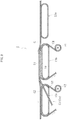
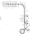
- FIG. 1 is a schematic side view for schematically illustrating an entire configuration of a manufacturing device 1 according to a first embodiment of the present invention.
- the manufacturing device 1 comprises, as main components, a forming unit 2 configured to form a glass film ribbon G, a direction changing unit 3 configured to change a moving direction of the glass film ribbon G from a vertically downward direction to a transverse direction, a transverse conveyance unit 4 configured to convey the glass film ribbon G in the transverse direction after the direction change, a cleaving unit 5 configured to cleave an unnecessary portion G1 including a selvage portion Gx of the glass film ribbon G that is being conveyed in the transverse direction by the transverse conveyance unit 4, and a take-up unit 6 configured to take up an effective portion G2 of the glass film ribbon G, which is obtained by removing the unnecessary portion G1 by cleaving with the cleaving unit 5, into a roll shape, to thereby manufacture a glass roll R.
- the thickness of the glass film ribbon G it is preferred that the thickness
- the forming unit 2 comprises a forming trough 7 having a substantially wedge shape in cross-section, in which an overflow groove 7a is formed in an upper end portion, cooling rollers 8 arranged immediately below the forming trough 7 and configured to hold a ribbon-like molten glass Gb from both front and back sides, and an annealer 10 arranged immediately below the cooling rollers 8 and comprising annealer rollers 9 arranged in a plurality of stages in a vertical direction.
- a main forming part 2a which is defined focusing on the action of the forming unit 2, comprises the forming trough 7 configured to cause the molten glass Ga overflowing from the top of the overflow groove 7a to flow downward along both side surfaces thereof and to be joined at a lower end thereof, to thereby form the ribbon-like molten glass Gb, and the cooling rollers 8 configured to form the glass film ribbon G having a predetermined width by regulating contraction in a width direction of the ribbon-like molten glass Gb.
- the annealer 10 configured to subject the glass film ribbon G to distortion removing treatment is provided below the main forming part 2a. In this manner, the forming unit 2 is constructed.
- Tension rollers 11 configured to hold the glass film ribbon G from both front and back sides are arranged below the annealer 10 so that tension for accelerating the reduction in thickness of the glass film ribbon G is applied to a portion between the tension rollers 11 and the cooling rollers 8 or a portion between the tension rollers 11 and the annealer rollers 9 located at any one position. Note that, in the case where the thickness of the glass film ribbon G is large, the tension rollers 11 serve as support rollers configured to prevent the downward stretching of the glass film ribbon G due to the own weight thereof.
- the direction changing unit 3 configured to change the moving direction of the glass film ribbon G from the vertically downward direction to the transverse direction is arranged below the tension rollers 11.
- aplurality of guide rollers 12 serving as guide members configured to guide the direction change of the glass film ribbon G are arranged in a curved shape on the back surface side of the glass film ribbon G, and the guide rollers 12 are held in contact with the back surface of the glass film ribbon G.
- the guide rollers 12 may support the glass film ribbon G in a non-contact manner by jetting an air stream or the like onto the back surface of the glass film ribbon G.
- one guide member serving as a belt conveyor formed into a curved shape may be used.
- the guide members may not be arranged in the direction changing unit 3, and the glass film ribbon G may be designed to change its direction without being influenced by an external force from the back surface side. Further, part of the plurality of guide rollers 12 may be held in contact with the back surface of the glass film ribbon G. Further, the guide rollers 12 may support only part (for example, both end portions in the width direction) of the glass film ribbon G.
- the first drive conveyor 13a serving as a conveyance unit, the stationary conveyor 13b installed at a fixed position so as not to be driven, and the second drive conveyor 13c serving as a conveyance unit are arranged adjacently in an order from the upstream side in the portion between the direction changing unit 3 and the take-up unit 6.
- the transverse conveyance unit 4 is configured to convey the glass film ribbon G (including the effective portion G2 after cleaving) in a horizontal direction in this embodiment, the transverse conveyance unit 4 may be inclined upward or downward with respect to the horizontal direction within a range of less than 45° (preferably, within a range of less than 30°).
- a wrinkle-smoothing unit 14 configured to smooth wrinkles generated in the glass film ribbon G is installed at a fixed position in an upper portion of the stationary conveyor 13b in the transverse conveyance unit 4.
- a conveyance sheet ribbon S1 having stretchability and formed of resin foam is interposed between the wrinkle-smoothing unit 14 and the glass film ribbon G.
- the conveyance sheet ribbon S1 has a lower surface capable of sliding on the wrinkle-smoothing unit 14 and an upper surface serving as a conveyance support surface configured to convey and support the glass film ribbon G.
- a cleaving unit 5 is arranged above a center portion of the conveyance path in the upper portion of the stationary conveyor 13b.
- the cleaving unit 5 is configured to cleave the unnecessary portion G1 including the thick selvage portion Gx to be formed in both end portions in a width direction (direction along the front and back surfaces and orthogonal to the conveyance direction) of the glass film ribbon G. That is, the stationary conveyor 13b comprises the cleaving unit 5 configured to cleave the unnecessary portion G1 of the glass film ribbon G on the conveyance path.
- the cleaving unit 5 comprises a thermal stress cleaving device 5a comprising a laser light irradiator 5aa configured to locally heat a boundary between the unnecessary portion G1 of the glass film ribbon G and the thin effective portion G2 on the center side in the width direction thereof (preset cleaving line A extending in a longitudinal direction illustrated in FIG. 3 ), and a mist water jetting unit 5ab configured to cool a part heated by the laser light irradiator 5aa. Then, the cleaved unnecessary portion G1 (to be exact, the unnecessary portion G1 including the selvage portion Gx) is sent obliquely downward with respect to a front side in the conveyance direction and discarded.
- a thermal stress cleaving device 5a comprising a laser light irradiator 5aa configured to locally heat a boundary between the unnecessary portion G1 of the glass film ribbon G and the thin effective portion G2 on the center side in the width direction thereof (preset cleaving line A extending in
- the take-up unit 6 is arranged on a downstream side of the transverse conveyance unit 4.
- the take-up unit 6 is configured to take up the glass film ribbon G (effective portion G2), which is conveyed with the unnecessary portion G1 including the selvage portion Gx removed, into the glass roll R.
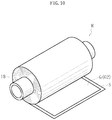
- a sheet roll r obtained by rolling a protective sheet S is arranged below the take-up unit 6, and the protective sheet S taken out from the sheet roll r is taken up so as to be laminated onto the glass film ribbon G (effective portion G2) by the take-up unit 6.
- the glass roll R is manufactured.
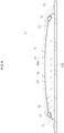
- FIG. 2 is an enlarged vertical sectional side view for illustrating the configuration of the transverse conveyance unit 4 in detail.
- the conveyance sheet ribbon S1 is taken out upward from a sheet roll r1 arranged below the stationary conveyor 13b and passes between the wrinkle-smoothing unit 14 and the glass film ribbon G in the upper portion of the stationary conveyor 13b to be sent downward from a downstream end portion of the stationary conveyor 13b.
- the conveyance sheet ribbon S1 is configured to be sent in an open loop shape (or in a closed loop shape although not shown) while sliding on the wrinkle-smoothing unit 14 by a drive unit (not shown) .
- the resin foam forming the sheet ribbon S1 is made of a resin such as polyethylene or polypropylene having a foaming ratio of from 5 times to 100 times and a thickness of from 0.1 mm to 3.0 mm.
- a sheet ribbon S2 having stretchability and formed of a resin foam is rolled on an upper surface portion of the second drive conveyor 13c, and an upper surface of the sheet ribbon S2 serves as a conveyance support surface configured to convey and support the effective portion G2 of the glass film ribbon G after the unnecessary portion G1 including the selvage portion Gx is removed by cleaving.
- a sheet roll r2 obtained by rolling the sheet ribbon S2 is arranged below the second drive conveyor 13c. The sheet ribbon S2 taken out upward from the sheet roll r2 is rolled around an upper surface portion of a belt from an upstream end portion of the second drive conveyor 13c, and is sent downward from a downstream end portion of the second drive conveyor 13c.
- the sheet ribbon S2 is configured to be sent in an open loop shape (or in a closed loop shape although not shown) so as to follow the upper surface portion of the belt of the second drive conveyor 13c.
- the resin foam forming the sheet ribbon S2 is made of a resin such as polypropylene or polyethylene having a foaming ratio of 5 times to 100 times and a thickness of from 0.1 mm to 3.0 mm.
- FIG. 3 is a plan view for illustrating an entire configuration of the wrinkle-smoothing unit 14.
- the wrinkle-smoothing unit 14 comprises an orthogonal rod-like body 15 arranged on an upstream side of a cleaving position 5x in the cleaving unit 5 for the glass film G so as to extend in a direction orthogonal to the conveyance direction, a bedplate 16 having a rectangular shape in plan view and arranged over a region from the upstream side to the downstream side of the cleaving position 5x, and a pair of parallel rod-like bodies 17 arranged in both end portions in a width direction (direction orthogonal to the conveyance direction) of the bedplate 16 so as to extend in a direction parallel to the conveyance direction.
- both ends in the width direction of the conveyance sheet ribbon S1 extend off both the ends in the width direction of the glass film ribbon G
- both ends in the width direction of the stationary conveyor 13b extend off both ends in the width direction of the conveyance sheet ribbon S1.
- both ends in the longitudinal direction of the orthogonal rod-like body 15 extend off both the ends in the width direction of the glass film ribbon G, but on the contrary, both the ends in the width direction of the glass film ribbon G may extend off both the ends in the longitudinal direction of the orthogonal rod-like body 15.
- both the ends in the width direction of the conveyance sheet ribbon S1 extend off both the ends in the width direction of the glass film ribbon G, but on the contrary, both the ends in the width direction of the glass film ribbon G may extend off both the ends in the width direction of the conveyance sheet ribbon S1.
- an upper end position of the orthogonal rod-like body 15 is set to be higher than an upper end position of the bedplate 16, and a difference dimension h of the height thereof is set to from 1 mm to 10 mm, preferably from 1 mm to 3 mm.
- the difference dimension h is set to 2 mm.
- the orthogonal rod-like body 15 and the bedplate 16 are separated in a close state, but it is only necessary that the separation distance thereof be set to such a degree that the glass film ribbon G is curved smoothly without being bent when being transferred from the orthogonal rod-like body 15 to the bedplate 16.
- the orthogonal rod-like body 15 and the bedplate 16 may be held in contact or substantially in contact with each other.
- the bedplate 16 forming the wrinkle-smoothing unit 14 is installed in a fixed manner on, for example, an upper surface portion of the stationary conveyor 13b, and an upper surface 16a thereof is gently curved so that a center portion in the width direction becomes higher than both end portions in the width direction.
- the illustrated sectional shape of the bedplate 16 may be, for example, a trapezoidal shape in which a center portion is flat and both end portions are inclined.
- the selvage portions Gx in both the end portions in the width direction of the glass film ribbon G are thicker than the effective portion G2, and the selvage portions Gx are each in a state of being floated while extending off both ends in the width direction of the upper surface of the bedplate 16.
- the glass film ribbon G is supported from below with the upper surface of the bedplate 16 through intermediation of the conveyance sheet ribbon S1, and in this state, both end portions of the glass film ribbon G including the selvage portions Gx are floated above both end portions of the conveyance sheet ribbon S1 while extending off both the ends in the width direction of the bedplate 16.
- the parallel rod-like bodies 17 forming the wrinkle-smoothing unit 14 are installed in a fixed manner on upper surface portions of the bedplate 16 at positions slightly closer to the center portion from both the ends in the width direction of the bedplate 16, and the upper end portions of the parallel rod-like bodies 17 each protrude upward from the upper surface of the bedplate 16. Further, a surface (upper surface) of each of the parallel rod-like bodies 17, which is brought into contact with a lower surface side of the glass film ribbon G, is curved in a convex shape, and a lower surface portion thereof is formed as a flat surface .
- the shape of a cross-section of the parallel rod-like body 17, which is orthogonal to the longitudinal direction, may be a circular shape, an oval shape, a square shape, or a rectangular shape. Note that, both ends in the longitudinal direction of the parallel rod-like body 17 are located at positions slightly closer to a center in the longitudinal direction from both corresponding ends of the bedplate 16.
- the glass film ribbon G that has reached the transverse conveyance unit 4 via the direction changing unit 3 from the forming unit 2 illustrated in FIG. 1 is thin and has flexibility, and hence wrinkles are generated in a wider range while the glass film ribbon G is being conveyed in the transverse direction by the first drive conveyor 13a.
- the wrinkles generated in the upper surface portion of the first drive conveyor 13a are smoothed properly with the wrinkle-smoothing unit 14 arranged on a downstream side thereof, and are eliminated to such a degree as not to cause trouble in laser cleaving on the periphery of a cleaving region by the cleaving unit 5.
- FIG. 7 is a schematic plan view for illustrating the action and effect of only the orthogonal rod-like body 15 being a component of the wrinkle-smoothing unit 14, and for convenience, the conveyance sheet ribbon and each conveyor are not shown.
- irregular wrinkles having various directivities as denoted by the reference symbol X are generated in an entire region in the width direction of the glass fil ribbon G.
- the wrinkles as denoted by the reference symbol Z are generated in both the end portions in the width direction owing to the presence of unevenness in the conveyance direction because the thickness of the selvage portions Gx located in both the end portions in the width direction of the glass film ribbon G are varied.
- FIG. 8 is a schematic plan view for illustrating the action and effect in the case where the bedplate 16 and the pair of parallel rod-like bodies 17 is arranged in addition to the orthogonal rod-like body 15 as the wrinkle-smoothing unit 14, and for convenience, the conveyance sheet ribbon and each conveyor are not shown. As illustrated in FIG.
- the wrinkles along the conveyance direction as denoted by the reference symbol Y described above become extremely short wrinkles at this time as denoted by the reference symbol y, and the wrinkles along the direction orthogonal to the conveyance direction as denoted by the reference symbol Z described above are converted into wrinkles in a region having an extremely narrow width in both the end portions in the width direction at this time as denoted by the reference symbol z.
- the first reason for the occurrence of such phenomenon resides in that, as illustrated in FIG.
- both the end portions in the width direction including the selvage portions Gx of the glass film ribbon G are floated while extending off both the ends in the width direction of the bedplate 16 (or the pair of parallel rod-like bodies 17), and hence the glass film ribbon G is not influenced by the unevenness in the selvage portions Gx described above.
- the second reason resides in that, due to the synergistic effect obtained by the fact that the selvage portions Gx are floated while extending off both the ends in the width direction of the bedplate 16 as described above and the fact that the center portion in the width direction of the upper surface of the bedplate 16 is higher than both the end portions in the width direction thereof, a tensile force directed to outer sides in the width direction as indicated by the arrow D is generated in the glass film ribbon G.
- the third reason resides in that the wrinkles generated along the conveyance direction are pulled into the vicinity of the parallel rod-like bodies 17 when the parallel rod-like bodies 17 lift up both the end portions in the width direction of the glass film ribbon G.
- a cleaving part Gc propagates linearly almost without being influenced by the wrinkles.
- the cleaving end surface of the glass film ribbon G3 after cleaving has proper properties.
- the bedplate 16 and the parallel rod-like bodies 17 are arranged over the region from the upstream side to the downstream side of the cleaving position 5x, and hence even after cleaving, the lift-up force still acts on the cleaving parts Gc or the tensile force directed to both the end sides in the width direction still acts on the unnecessary portions G1 including the selvage portions Gx. Therefore, the opposing cleaving end surfaces in the cleaving parts Gc are to be separated from each other. Accordingly, the occurrence of damages and cracks caused by the contact between the opposing cleaving end surfaces in the cleaving parts Gc is avoided effectively, with the result that the cleaving end surfaces having proper properties can be ensured.
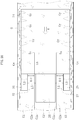
- FIG. 11 is a plan view for illustrating a configuration of a main portion of a manufacturing device 1 according to a second embodiment of the present invention.
- FIG. 12 is a vertical sectional front view for similarly illustrating the configuration of the main portion of the manufacturing device 1. As illustrated in each of FIG. 11 and FIG.
- the manufacturing device 1 according to the second embodiment is different from the manufacturing device 1 according to the first embodiment described above in that a pair of raising bodies 20, which is arranged in a region including the cleaving position 5x and extending from the cleaving position 5x to each of an upstream side and a downstream side in the direction parallel to the conveyance direction, is added as a component of the wrinkle-smoothing unit 14, and in that a pair of holding bodies 21 configured to hold the selvage portions Gx in both the end portions in the width direction of the glass film ribbon G from above is added.
- the other components are the same as those of the first embodiment described above. Therefore, in the following description, the components common to both the embodiments are denoted by the same reference symbols, and the descriptions thereof are omitted.
- the raising body 20 is installed in a fixed manner on an upper surface portion of the bedplate 16 and protrudes upward from the upper surface of the bedplate 16, and the position in the width direction at which the raising body 20 is installed is defined as the position including the cleaving part Gc and the cleaving position 5x of the glass film ribbon G. Further, the length along the conveyance direction of the raising body 20 is set to be equal or substantially equal to the length along the conveyance direction of the bedplate 16.
- the cleaving position 5x illustrated in FIG. 11 is also a position at which the glass film ribbon G is actually cleaved, specifically, a position to be set as a leading end when the glass film ribbon G is cleaved.
- a protrusion height t of the raising body 20 from the upper surface of the bedplate 16 falls preferably within a range of from ⁇ [0.05/thickness of glass film ribbon G (mm)](mm) ⁇ to ⁇ [1.00/thickness of glass film ribbon G (mm) ] (mm) ⁇ , more preferably within a range of from ⁇ [0.10/thickness of glass film ribbon G (mm) ] (mm) ⁇ to ⁇ [0.75/thickness of glass film ribbon G (mm) ] (mm) ⁇ .
- a width w1 of the raising body 20 falls preferably within a range of 500 times to 10,000 times, more preferably within a range of from 1,000 times to 5,000 times of the thickness of the glass film ribbon G.
- the width w1 is excessively large, the raising body 20 lifts up a large region of the glass film ribbon G, and hence it becomes difficult to allow the glass film ribbon G to have sufficient tension, with the result that the effect of the lift-up may not be obtained.
- the width w1 is excessively small, a region of the glass film ribbon G lifted up by the raising body 20 becomes insufficient, and it becomes difficult to allow the glass film ribbon G to have sufficient tension, with the result that the effect of the lift-up may not be obtained even in this case.
- the width of the raising body 20 may be constant over the region from the upstream side to the downstream side of the cleaving position 5x.
- the width may become gradually smaller as approaching from the upstream side to the downstream side, or a part having a constant width on the downstream side may be narrower than a part having a constant width on the upstream side, with the cleaving position 5x being a boundary.
- the length of the raising body 20 is preferably 100 mm or more, more preferably 200 mm or more from the cleaving position 5x to the upstream side. Further, the length of the raising body 20 is preferably 100 mm or more, more preferably 200 mm or more from the cleaving position 5x to the downstream side. When the length of the raising body 20 is excessively small in any of the upstream part and the downstream part of the cleaving position 5x, the effect of smoothing wrinkles generated in the glass film ribbon G may not be obtained sufficiently.
- the shape of a cross-section of the raising body 20, which is orthogonal to the longitudinal direction may be a rectangular shape as in an example illustrated in FIG. 12
- the shape may be a circular shape, an oval shape, a square shape, or the like. In any case, it is only necessary that the raising body 20 lift up the glass film ribbon G upward in a convex curved shape.
- the holding bodies 21 extend in the direction parallel to the conveyance direction at positions in the width direction at which the selvage portions Gx are located in both the end portions in the width direction of the glass film ribbon G.
- the holding bodies 21 are suspended and supported by a portal support pillar fixed on a floor surface, the stationary conveyor 13b, or the like to be installed at fixed positions and arranged over the region from the upstream side to the downstream side of the cleaving positions 5x.
- the role of the holding body 21 is as follows. That is, in general, in the selvage portion Gx in each of both the end portions in the width direction of the glass film ribbon G, parts that are to be convex upward and parts that are to be convex downward are repeatedly formed adjacently in the longitudinal direction during transverse conveyance, and the following situation has occurred frequently. Along with the conveyance, the parts that are convex upward are inverted to parts that are convex downward, and the parts that are convex downward are inverted to the parts that are convex upward. When such situation occurs, vibration occurs in the selvage portion Gx of the glass film ribbon G, and the vibration propagates to the cleaving position 5x. Therefore, the cleaving is inevitably stopped.
- a dimension w2 of the width of a lower surface of the holding body 21, which is held in contact with an upper surface of the selvage portion Gx of the glass film ribbon G falls preferably within a range of from 0.01 time to 0.5 time, more preferably within a range of from 0.05 time to 0.25 time of a dimension w3 from the cleaving position 5x of the glass film ribbon G to the outer end in the width direction of the selvage portion Gx.
- the length of the holding body 21 is preferably 100 mm or more, more preferably 200 mm or more from the cleaving position 5x to the upstream side, and further, the length of the holding body 21 is preferably 100 mm or more, more preferably 200 mm or more from the cleaving position 5x to the downstream side.
- the length of the holding body 21 is excessively small in any of the upstream part and the downstream part of the cleaving position 5x, the effect of suppressing the vibration of the selvage portion Gx becomes insufficient.
- the length of the holding body 21 in the upstream part of the cleaving position 5x may be larger than that in the downstream part.
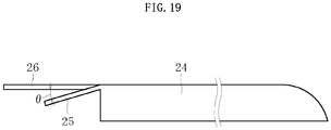
- the lower surface of the holding body 21 be inclined along a direction in which the selvage portion Gx of the glass film ribbon G hangs down, and that an angle ⁇ of the lower surface of the holding body 21 fall within ⁇ 20° with reference to a hang-down line L of the selvage portion Gx illustrated in FIG. 12 .
- the inclination angle of the lower surface of the holding body 21 from a horizontal surface is excessively large, a force of pressing the selvage portion Gx of the glass film ribbon G downward tends to become insufficient, and hence the effect of suppressing the vibration of the selvage portion Gx becomes insufficient.
- the lower surface of the holding body 21 is preferably flat, and the material therefor is preferably a resin, such as polyethylene, polypropylene, or Teflon (trademark) having small friction resistance against the glass film ribbon G.
- the holding body 21 is not limited to the holding body having a plate shape and may be a multiple roller (the material is preferably the same resin as described above) capable of rolling on the upper surface of the selvage portion Gx in the longitudinal direction, or the like.
- the glass film ribbon G is lifted up on the periphery of the cleaving position 5x by additionally arranging the raising body 20. Therefore, in particular, the glass film ribbon G having small thickness is allowed to have tension at a part in which wrinkles are liable to be generated, and the sufficient effect of smoothing the wrinkles can be obtained.
- the manufacturing device 1 according to the first embodiment described above is suitable for smoothing wrinkles in the glass film ribbon G having a thickness of 50 ⁇ m or more
- the manufacturing device 1 according to the second embodiment is suitable for smoothing wrinkles in the glass film ribbon G having a thickness of less than 50 ⁇ m, in particular, a thickness of 40 ⁇ m or less or 30 ⁇ m or less.
- the holding body 21 is additionally arranged. Therefore, the factor for stopping cleaving, in which vibration occurs in the selvage portion Gx of the glass film ribbon G, and the vibration propagates to the cleaving position 5x, is eliminated, with the result that smooth cleaving can be performed.
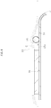
- FIG. 14 is a schematic side view for schematically illustrating an entire configuration of a manufacturing device 1 according to a third embodiment of the present invention.
- the moving path of the glass film ribbon G from the direction changing unit 3 to the transverse conveyance unit 4 is not positioned below the moving path of the glass film ribbon G in the transverse conveyance unit 4.
- the manufacturing device 1 according to the third embodiment is constructed such that the glass film ribbon G drawn vertically downward from the forming unit 2 follows the following moving path.
- the glass film ribbon G hangs down below the moving path in the transverse conveyance unit 4 and shifts upward to reach the transverse conveyance unit 4.
- the other configurations are the same as those of the manufacturing device 1 according to the first embodiment described above. Therefore, the detailed illustration is omitted, and in the illustrated configurations, the common components are denoted by the same reference symbols, and the descriptions thereof are omitted.
- FIG. 15 is a schematic side view for schematically illustrating an entire configuration of a manufacturing device 1 according to a fourth embodiment of the present invention.
- the manufacturing device 1 is used for carrying out a roll-to-roll process, and takes out the glass film ribbon G from one glass roll Ra (right side of FIG. 5 ) and takes up the glass film ribbon G into the other glass roll R (left side of FIG. 5 ) .
- the transverse conveyance unit 4 configured to convey the glass film ribbon G in the transverse direction is provided on a downstream side of the one glass roll Ra and on an upstream side of the other glass roll R.
- the manufacturing device 1 according to the fourth embodiment is the same as the manufacturing device 1 according to the first and second embodiment described above in that the wrinkle-smoothing unit 14 and the holding bodies 21 are arranged in the transverse conveyance unit 4, and in the configuration of the wrinkle-smoothing unit 14 and the holding bodies 21, the positional relationship between each of the wrinkle-smoothing unit 14 and the holding bodies 21 and the cleaving portions 5, and the like. That is, the manufacturing device 1 according to the fourth embodiment is different from the manufacturing device 1 according to the first embodiment described above in that the glass film ribbon G taken out from the one glass roll Ra is sent to the transverse conveyance unit 4, and along with this, a protective sheet Sa taken out from the one glass roll Ra is taken up into a sheet roll ra.
- the other configurations are the same as those of the manufacturing device 1 according to the first embodiment described above. Therefore, the components common to both the embodiments are denoted by the same reference symbols, and the descriptions thereof are omitted.
- the one glass roll Ra is obtained by taking up the glass film ribbon G including the selvage portion Gx, and the unnecessary portion G1 including the selvage portion Gx is removed with the cleaving unit 5.
- the one glass roll Ra may be obtained by taking up the glass film ribbon from which the selvage portion Gx has been removed by cleaving, and in this case, the glass film ribbon G is cleaved by the cleaving unit 5 along one or a plurality of preset cleaving lines extending in the longitudinal direction.
- the wrinkle-smoothing unit 14 comprises the orthogonal rod-like body 15, the bedplate 16, the parallel rod-like body 17, and the raising body 20.
- the wrinkle-smoothing unit 14 may comprise only the orthogonal rod-like body 15, only the bedplate 16, or only the parallel rod-like body 17.
- the wrinkle-smoothing unit 14 may comprise only the raising body 20.
- the wrinkle-smoothing unit 14 comprises only the bedplate 16, only the parallel rod-like body 17, or only the raising body 20, it is preferred that the sliding resistance of the wrinkle-smoothing unit 14 against the lower surface of the conveyance sheet ribbon S1 be decreased by setting an upstream end surface of the bedplate 16, an upstream end surface of the parallel rod-like body 17, or an upstream end surface of the raising body 20 to an inclined surface or a convex curved surface that becomes gradually higher as approaching to the downstream side, with the upstream side being lowered.
- the wrinkle-smoothing unit 14 and the holding body 21 are arranged on the stationary conveyor 13b in the transverse conveyance unit 4.
- the wrinkle-smoothing unit 14 and the holding body 21 may be arranged in an upper portion of a base portion installed in a fixed manner in a without using the stationary conveyor 13b.
- the conveyance sheet ribbon S1 is interposed between the glass film ribbon G and the wrinkle-smoothing unit 14.
- the glass film ribbon G may be slid on an upper surface portion of the wrinkle-smoothing unit 14 without using the conveyance sheet ribbon S1. Note that, in this case, it is necessary to prevent each component of the wrinkle-smoothing unit 14 from causing unacceptable scars and the like on a lower surface of the glass film ribbon G.
- two drive conveyors are used as components of the transverse conveyance unit 4.
- one drive conveyor may be used as a component of the transverse conveyance unit 4. Note that, in this case, it is necessary to install the wrinkle-smoothing unit 14 and the holding body 21 at fixed positions in a state of being isolated from the drive conveyor. Note that, three or more drive conveyors may be used as components of the transverse conveyance unit 4.
- FIG. 16 is a schematic side view for schematically illustrating an entire configuration of a manufacturing device 1 according to a fifth embodiment.
- FIG. 17 is an enlarged vertical sectional side view for illustrating a configuration of the transverse conveyance unit 4 of the manufacturing device 1 in detail.
- the manufacturing device 1 according to the fifth embodiment is different from the manufacturing device 1 according to the first embodiment described above in that a surface plate 24, an unnecessary portion supporting part 25, and an effective portion supporting part 26 are arranged in the upper portion of the stationary conveyor 13b in the transverse conveyance unit 4 in place of the wrinkle-smoothing unit 14.
- the components common to those of the manufacturing device 1 according to the first embodiment described above are denoted by the same reference symbols, and the descriptions thereof are omitted.
- the surface plate 24 configured to guide the glass film ribbon G on the periphery of the cleaving position, and the unnecessary portion supporting part 25 and the effective portion supporting part 26, which are configured to respectively support and guide the unnecessary portion G1 and the effective portion G2 (immediately) after the glass film ribbon G is cleaved, are installed at fixed positions.
- FIG. 18 is a plan view for illustrating an entire configuration of the surface plate 24, the unnecessary portion supporting part 25, and the effective portion supporting part 26.
- the surface plate 24 is a plate-like body having a substantially rectangular shape and installed at a fixed position so that the cleaving position 5x for the glass film ribbon G is located above the surface plate 24. Then, on a downstream end in the conveyance direction of the surface plate 24, the unnecessary portion supporting parts 25 are formed to protrude from both the end portions in the width direction, and the effective portion supporting part 26 is formed to protrude from the center side in the width direction between the unnecessary portion supporting parts 25.
- both edges 24a on the outer sides in the width direction of the surface plate 24 and edges 25a on the outer sides in the width direction of the unnecessary portion supporting parts 25 are connected to each other linearly.
- the unnecessary portion supporting part 25 and the effective portion supporting part 26 both have a substantially rectangular shape, and a dimension L1 of the unnecessary portion supporting part 25 protruding from the downstream end in the conveyance direction of the surface plate 24 is from 0.5 time to 3 times of the width of the unnecessary portion G1. Further, a dimension L2 of the effective portion supporting part 26 protruding from the downstream end in the conveyance direction of the surface plate 24 is 1 time to 3 times of the dimension L1 of the unnecessary portion supporting part 25. Note that, as can be understood from FIG.
- both the ends in the width direction of the conveyance sheet ribbon S1 extend off both the ends in the width direction of the glass film ribbon G, and both the ends in the width direction of the stationary conveyor 13b extend off both the ends in the width direction of the conveyance sheet ribbon S1.
- both the ends in the width direction of the conveyance sheet ribbon S1 extend off both the ends in the width direction of the glass film ribbon G.
- both the ends in the width direction of the glass film ribbon G may extend off both the ends in the width direction of the conveyance sheet ribbon S1.
- the cleaving end surfaces G2a of the effective portions G2 respectively slightly extend off both the end portions in the width direction of the effective portion supporting part 26, and hence the same relationship also holds in gaps formed between both the ends in the width direction of the effective portion supporting part 26 and the inward ends in the width direction of the unnecessary portion supporting parts 25.
- the length L3 in the width direction of the unnecessary portion supporting part 25 may be preferably from 0.1 time to 2.0 times, more preferably from 0.2 time to 0.5 time, still more preferably from 0.25 time to 0.3 time of a dimension L5 in the width direction in the gap.
- a dimension L6 from the cleaving position 5x of the glass film ribbon G to the downstream end in the conveyance direction of the surface plate 24 is preferably from 0.5 time to 3 times of the width of the effective portion G2.
- the unnecessary portion supporting part 25 supports the unnecessary portion G1 after the glass film ribbon G is cleaved, the selvage portion Gx of the unnecessary portion G1 is put into a state of protruding outward from an outward end in the width direction of the unnecessary portion supporting part 25. Further, in overall view, the unnecessary portion supporting part 25 supports a position closer to the outer side in the width direction of the unnecessary portion G1. Then, as illustrated in FIG. 21 , a distance between a conveyance track of the unnecessary portion G1, which is formed by the unnecessary portion supporting part 25, and a conveyance track of the effective portion G2, which is formed by the effective portion supporting part 26, is gradually increased as approaching to the downstream side in the conveyance direction.
- the glass film ribbon G that has reached the transverse conveyance unit 4 via the direction changing unit 3 from the forming unit 2 illustrated in FIG. 16 is conveyed in the transverse direction by the first drive conveyor 13a and then conveyed in the transverse direction so as to be transferred to the upper portion of the stationary conveyor 13b.
- the glass film ribbon G, and the unnecessary portion G1 and the effective portion G2 after cleaving of the glass film ribbon G are conveyed by the conveyance sheet ribbon S1 that moves while sliding on the surface plate 24, the unnecessary portion supporting part 25, and the effective portion supporting part 26.
- the selvage portion Gx having large weight protrudes to hang down from the outward end in the width direction of the unnecessary portion supporting part 25, and hence the unnecessary portion G1 is to be separated from the effective portion G2.
- the unnecessary portion supporting part 25 is put into a state of supporting the unnecessary portion G1 without being influenced by waviness caused in the selvage portion Gx.
- the cleaving position 5x of the glass film ribbon G is separated by the dimension L6 from the upstream end in the conveyance direction of the unnecessary portion supporting part 25 for the following reason. That is, as illustrated in FIG.
- the conveyance track of the unnecessary portion supporting part 25 is different from that of the effective portion supporting part 26, and hence if the cleaving position 5x is positioned at the upstream end in the conveyance direction of the unnecessary portion supporting part 25, an inappropriate stress acts on the cleaving position 5x, with the result that proper cleaving may not be performed.
- the gap 27 in the width direction having a sufficient size is located between the unnecessary portion supporting part 25 and the effective portion G2 (effective portion supporting part 26), and hence a peripheral portion of an inward end in the width direction of the unnecessary portion G1 supported by the unnecessary portion supporting part 25 is put into a state of hanging down as illustrated in FIG. 22 .
- the unnecessary portion supporting part 25 supports the position closer to the outer side in the width direction of the unnecessary portion G, and hence the unnecessary portion G1 is supported by the unnecessary portion supporting part 25 in a state in which a protruding dimension of the unnecessary portion G1 to the inner side in the width direction is set to be large. This causes the peripheral portion of the inward end in the width direction of the unnecessary portion G1 to hang down significantly.
- the unnecessary portion G1 supported by the unnecessary portion supporting part 25 is in a state in which the peripheral portion of the inward end in the width direction thereof hangs down significantly. Therefore, the situation in which the cleaving end surface G1a of the unnecessary portion G1 and the cleaving end surface G2a of the effective portion G2 rub against each other can be avoided. In such case, the cleaving position 5x of the glass film ribbon G can be positioned at the upstream end in the conveyance direction of the unnecessary portion supporting part 25 or the vicinity thereof.
- the unnecessary portion G1 that is conveyed while being supported by the unnecessary portion supporting part 25 is sent to a disposal unit (not shown) to be shredded.
- the effective portion G2 that is conveyed while being supported by the effective portion supporting part 26 reaches the take-up unit 6 and is finally taken up into the glass roll R by rolling the glass film ribbon G (effective portion G2) and the protective sheet S around the roll core 18 in a laminated state in the same way as in FIG. 10 described above.
- the glass roll R thus obtained has high quality with extremely few scars of the cleaving end surfaces and the like.
- FIG. 23 and FIG. 24 are views for illustrating a configuration of a main portion of a manufacturing device 1 according to a sixth.
- the manufacturing device 1 according to the sixth embodiment is different from the manufacturing device 1 according to the fifth embodiment described above in that, in the upper portion of the stationary conveyor 13b, the conveyance sheet ribbon is not interposed between each of the surface plate 24, the unnecessary portion supporting part 25, and the effective portion supporting part 26 and the glass film ribbon G (including the unnecessary portion G1 and the effective portion G2).
- FIG. 25 is a view for illustrating a configuration of a main portion of a manufacturing device 1 according to a seventh embodiment.
- the manufacturing device 1 according to the seventh embodiment is different from the manufacturing device 1 according to the sixth embodiment described above in that the unnecessary portion supporting part 25 is inclined downward from the outer side in the width direction to the inner side in the width direction.
- the conveyance sheet ribbon may be interposed between each of the surface plate, the unnecessary portion supporting part 25, and the effective portion supporting part 26 and the glass film ribbon G (including the unnecessary portion G1 and the effective portion G2) .
- FIG. 26 is a view for illustrating a configuration of a main portion of a manufacturing device 1 according to an eighth embodiment.
- the manufacturing device 1 according to the eighth embodiment is different from the manufacturing device 1 according to the sixth embodiment described above in that the unnecessary portion supporting part 25 is inclined downward from the inner side in the width direction to the outer side in the width direction.
- the conveyance sheet ribbon may be interposed between each of the surface plate, the unnecessary portion supporting part 25, and the effective portion supporting part 26 and the glass film ribbon G (including the unnecessary portion G1 and the effective portion G2) .
- FIG. 27 is a schematic side view for schematically illustrating an entire configuration of a manufacturing device 1 according to a ninth embodiment.
- the manufacturing device 1 is used for carrying out a roll-to-roll process, and takes out the glass film ribbon G from one glass roll Ra (right side of FIG. 27 ) and takes up the glass film ribbon G into the other glass roll R (left side of FIG. 27 ).
- the glass film ribbon G is taken out from the one glass roll Ra, and along with this, the protective sheet Sa taken out from the one glass roll Ra is taken up into the sheet roll ra.
- the unnecessary portion G1 is located in each of both the end portions in the width direction of the glass film ribbon G or only in one end portion in the width direction. Then, in order to resize the dimension in the width direction of the glass film ribbon G, the unnecessary portion G1 may be removed by cleaving.
- the unnecessary portion supporting part 25 is formed to protrude from each of both the end portions in the width direction or the one end portion in the width direction at the downstream end in the conveyance direction of the surface plate 24, and the effective portion supporting part 26 is formed to protrude from the center side in the width direction between the unnecessary portion supporting parts 25 at the downstream end in the conveyance direction of the surface plate 24.
- the unnecessary portions G1 are located in both the end portions in the width direction of the glass film ribbon G, as illustrated in FIG. 28a , a pair of unnecessary portions G1 after cleaving is supported by a pair of unnecessary portion supporting parts 25.
- the surface plate 24, the unnecessary portion supporting part 25, and the effective portion supporting part 26 are arranged on the stationary conveyor 13b in the transverse conveyance unit 4.
- the surface plate 24, the unnecessary portion supporting part 25, and the effective portion supporting part 26 may be arranged in an upper portion of a base portion installed in a fixed manner without using the stationary conveyor 13b.
- two drive conveyors are used as components of the transverse conveyance unit 4.
- one drive conveyor may be used as a component of the transverse conveyance unit 4. Note that, in this case, it is necessary to install the surface plate 24, the unnecessary portion supporting part 25, and the effective portion supporting part 26 at fixed positions in a state of being isolated from the drive conveyor. Note that, three or more drive conveyors maybe used as components of the transverse conveyance unit 4.
- the unnecessary portion supporting part 25 and the effective portion supporting part 26 are formed to protrude from the downstream end in the conveyance direction of the surface plate 24.
- the effective portion supporting part 26 may not be provided.
- the conveyors 13a, 13b, and 13c arranged in the transverse conveyance unit 4 are each formed of a belt conveyor.
- a part or a whole of the conveyors may be constructed by appropriately combining roller conveyors having a configuration in which a plurality (a large number) of rollers rotate, a floating conveyance unit, and the like.
- the unnecessary portion supporting part 25 may be formed of such roller conveyors and the like instead of the plate-like body.
- the overflow down-draw method is employed for forming the glass film ribbon G.
- other down-draw methods such as a slot down-draw method, a re-draw method, and the like may also be employed.
- a float method involving drawing a glass film ribbon from a float bath and conveying the glass film ribbon by a transverse conveyance unit may also be employed.
- all the embodiments described above have a configuration including the take-up unit 6 configured to take up, into a roll shape, the glass film ribbon G2 from which the selvage portion is removed by cleaving with the cleaving unit 5, to thereby form the glass roll R.
- all the embodiments described above may have such a configuration not including the take-up unit 6 that the glass film ribbon (effective portion G2) from which the unnecessary portion G1 is removed by cleaving with the cleaving unit 5 is cut into a rectangular shape by a predetermined length in the longitudinal direction, to thereby form a glass film laminate having a protective sheet interposed between a plurality of respective rectangular glass films.
Landscapes
- Chemical & Material Sciences (AREA)
- Engineering & Computer Science (AREA)
- Materials Engineering (AREA)
- Organic Chemistry (AREA)
- Physics & Mathematics (AREA)
- Health & Medical Sciences (AREA)
- Toxicology (AREA)
- Optics & Photonics (AREA)
- Thermal Sciences (AREA)
- Re-Forming, After-Treatment, Cutting And Transporting Of Glass Products (AREA)
Priority Applications (1)
| Application Number | Priority Date | Filing Date | Title |
|---|---|---|---|
| EP17199114.4A EP3326978B1 (en) | 2013-08-28 | 2014-08-22 | Glass film ribbon manufacturing method and glass film ribbon manufacturing device |
Applications Claiming Priority (3)
| Application Number | Priority Date | Filing Date | Title |
|---|---|---|---|
| JP2013176819A JP6136070B2 (ja) | 2013-08-28 | 2013-08-28 | ガラスフィルムリボン製造方法及びガラスフィルムリボン製造装置 |
| JP2013176817 | 2013-08-28 | ||
| PCT/JP2014/071972 WO2015029888A1 (ja) | 2013-08-28 | 2014-08-22 | ガラスフィルムリボン製造方法及びガラスフィルムリボン製造装置 |
Related Child Applications (2)
| Application Number | Title | Priority Date | Filing Date |
|---|---|---|---|
| EP17199114.4A Division EP3326978B1 (en) | 2013-08-28 | 2014-08-22 | Glass film ribbon manufacturing method and glass film ribbon manufacturing device |
| EP17199114.4A Division-Into EP3326978B1 (en) | 2013-08-28 | 2014-08-22 | Glass film ribbon manufacturing method and glass film ribbon manufacturing device |
Publications (3)
| Publication Number | Publication Date |
|---|---|
| EP3040317A1 EP3040317A1 (en) | 2016-07-06 |
| EP3040317A4 EP3040317A4 (en) | 2017-07-19 |
| EP3040317B1 true EP3040317B1 (en) | 2019-09-25 |
Family
ID=52586447
Family Applications (2)
| Application Number | Title | Priority Date | Filing Date |
|---|---|---|---|
| EP17199114.4A Active EP3326978B1 (en) | 2013-08-28 | 2014-08-22 | Glass film ribbon manufacturing method and glass film ribbon manufacturing device |
| EP14839514.8A Active EP3040317B1 (en) | 2013-08-28 | 2014-08-22 | Glass film ribbon manufacturing method and glass film ribbon manufacturing device |
Family Applications Before (1)
| Application Number | Title | Priority Date | Filing Date |
|---|---|---|---|
| EP17199114.4A Active EP3326978B1 (en) | 2013-08-28 | 2014-08-22 | Glass film ribbon manufacturing method and glass film ribbon manufacturing device |
Country Status (6)
| Country | Link |
|---|---|
| US (2) | US9932259B2 (zh) |
| EP (2) | EP3326978B1 (zh) |
| KR (1) | KR102184301B1 (zh) |
| CN (2) | CN107382048B (zh) |
| TW (2) | TWI625312B (zh) |
| WO (1) | WO2015029888A1 (zh) |
Families Citing this family (21)
| Publication number | Priority date | Publication date | Assignee | Title |
|---|---|---|---|---|
| CN108367960B (zh) * | 2015-12-01 | 2021-05-18 | 康宁股份有限公司 | 玻璃网分离装置和方法 |
| US20190185363A1 (en) * | 2016-06-03 | 2019-06-20 | Corning Incorporated | Apparatus and method of managing mechanically induced stress on a crack tip when separating a flexible glass ribbon |
| JP6796282B2 (ja) * | 2016-10-11 | 2020-12-09 | 日本電気硝子株式会社 | ガラスフィルムの製造方法 |
| WO2018105489A1 (ja) * | 2016-12-06 | 2018-06-14 | 日本電気硝子株式会社 | 帯状ガラスフィルムの品質検査方法、及び、ガラスロール |
| JP6748920B2 (ja) * | 2017-03-13 | 2020-09-02 | 日本電気硝子株式会社 | ガラスフィルムの製造方法 |
| JP6720900B2 (ja) * | 2017-03-14 | 2020-07-08 | 日本電気硝子株式会社 | ガラスロールの製造方法 |
| JP6909403B2 (ja) * | 2017-07-31 | 2021-07-28 | 日本電気硝子株式会社 | ガラスフィルムの製造方法 |
| JP6839419B2 (ja) * | 2017-07-31 | 2021-03-10 | 日本電気硝子株式会社 | ガラスフィルムの製造方法 |
| KR102583667B1 (ko) | 2017-10-30 | 2023-10-04 | 코닝 인코포레이티드 | 얇은 유리 리본을 프로세스하기 위한 시스템 및 방법 |
| KR102660244B1 (ko) * | 2017-10-31 | 2024-04-25 | 코닝 인코포레이티드 | 얇은 유리 리본을 프로세스하기 위한 시스템 및 방법 |
| JP6883282B2 (ja) * | 2017-11-27 | 2021-06-09 | 日本電気硝子株式会社 | ガラスロールの製造方法 |
| JP7054170B2 (ja) * | 2017-11-30 | 2022-04-13 | 三星ダイヤモンド工業株式会社 | ベルトコンベヤ装置 |
| WO2019151246A1 (ja) * | 2018-01-31 | 2019-08-08 | 日本電気硝子株式会社 | ガラスロール、ガラスロールの製造方法および品質評価方法 |
| JP7148837B2 (ja) * | 2018-06-22 | 2022-10-06 | 日本電気硝子株式会社 | ガラスロールの製造方法 |
| KR20220063203A (ko) * | 2019-09-12 | 2022-05-17 | 코닝 인코포레이티드 | 유리 리본 제조 방법 및 장치 |
| DE102019129036A1 (de) * | 2019-10-28 | 2021-04-29 | Schott Ag | Verfahren zur Herstellung von Glasscheiben und verfahrensgemäß hergestellte Glasscheibe sowie deren Verwendung |
| JPWO2021131617A1 (zh) * | 2019-12-23 | 2021-07-01 | ||
| DE112020006293T5 (de) * | 2019-12-24 | 2022-12-01 | Nippon Electric Glass Co., Ltd. | Verfahren zur herstellung eines glasfilms, verfahren zur herstellung einer glasrolle und vorrichtung zur herstellung eines glasfilms |
| JP2022093901A (ja) * | 2020-12-14 | 2022-06-24 | 日本電気硝子株式会社 | ガラス板の製造方法および製造装置 |
| JP2022108103A (ja) * | 2021-01-12 | 2022-07-25 | 日本電気硝子株式会社 | ガラスフィルムの製造方法 |
| WO2023177539A1 (en) * | 2022-03-15 | 2023-09-21 | Corning Incorporated | Methods and apparatus for manufacturing a ribbon |
Family Cites Families (26)
| Publication number | Priority date | Publication date | Assignee | Title |
|---|---|---|---|---|
| GB1246481A (en) * | 1968-03-29 | 1971-09-15 | Pilkington Brothers Ltd | Improvements in or relating to the cutting of glass |
| NO134614C (zh) * | 1972-10-12 | 1976-11-17 | Glaverbel | |
| JPS5910099Y2 (ja) * | 1979-10-22 | 1984-03-30 | セントラル硝子株式会社 | ガラス板折割分離装置 |
| JPS5665931A (en) | 1979-10-31 | 1981-06-04 | Kobe Steel Ltd | Manufacture of cold-rolled steel sheet for press formation |
| JPS6076318A (ja) * | 1983-10-04 | 1985-04-30 | Toray Ind Inc | フイルムのしわ延ばし装置 |
| JPH08175726A (ja) * | 1994-12-22 | 1996-07-09 | Toray Ind Inc | シート状物のしわ延ばしロール |
| JP5522516B2 (ja) | 2009-12-07 | 2014-06-18 | 日本電気硝子株式会社 | 板状ガラスの切断方法及びその切断装置 |
| JP5418977B2 (ja) * | 2009-12-08 | 2014-02-19 | 日本電気硝子株式会社 | ガラスフィルムの切断方法及びその切断装置 |
| JP5532219B2 (ja) * | 2010-01-18 | 2014-06-25 | 日本電気硝子株式会社 | 板状ガラスの切断方法及びその切断装置 |
| US9656901B2 (en) * | 2010-03-03 | 2017-05-23 | Nippon Electric Glass Co., Ltd. | Method of manufacturing a glass roll |
| JP5669001B2 (ja) * | 2010-07-22 | 2015-02-12 | 日本電気硝子株式会社 | ガラスフィルムの割断方法、ガラスロールの製造方法、及びガラスフィルムの割断装置 |
| JP5645063B2 (ja) * | 2010-07-23 | 2014-12-24 | 日本電気硝子株式会社 | ガラスフィルムの製造装置および製造方法 |
| JP5696393B2 (ja) * | 2010-08-02 | 2015-04-08 | 日本電気硝子株式会社 | ガラスフィルムの割断方法 |
| JP2012096936A (ja) | 2010-10-29 | 2012-05-24 | Asahi Glass Co Ltd | ガラスリボンの耳切断装置および耳切断方法とガラス製品の製造装置および製造方法 |
| JP5743182B2 (ja) * | 2010-11-19 | 2015-07-01 | 日本電気硝子株式会社 | ガラスフィルムの製造方法 |
| JP5617556B2 (ja) * | 2010-11-22 | 2014-11-05 | 日本電気硝子株式会社 | 帯状ガラスフィルム割断装置及び帯状ガラスフィルム割断方法 |
| US9790121B2 (en) | 2011-03-30 | 2017-10-17 | Corning Incorporated | Methods of fabricating a glass ribbon |
| CN103347827B (zh) * | 2011-06-07 | 2016-10-26 | 日本电气硝子株式会社 | 板状玻璃的切断方法及其切断装置 |
| WO2012169025A1 (ja) * | 2011-06-08 | 2012-12-13 | 日本電気硝子株式会社 | 板状ガラスの切断方法及びその切断装置 |
| TWI586612B (zh) * | 2011-11-18 | 2017-06-11 | 康寧公司 | 用於修整移動玻璃帶之設備及方法 |
| TW201412658A (zh) * | 2012-09-26 | 2014-04-01 | Corning Inc | 用於可撓式玻璃帶之邊緣修正管理 |
| US9216924B2 (en) * | 2012-11-09 | 2015-12-22 | Corning Incorporated | Methods of processing a glass ribbon |
| KR20150084758A (ko) * | 2012-11-13 | 2015-07-22 | 니폰 덴키 가라스 가부시키가이샤 | 판 유리의 제조 방법 및 제조 장치 |
| CN105102384B (zh) * | 2012-11-29 | 2017-06-23 | 康宁股份有限公司 | 用于制造具有不同宽度的玻璃带的方法和装置 |
| US9919381B2 (en) * | 2013-01-30 | 2018-03-20 | Corning Incorporated | Apparatus and methods for continuous laser cutting of flexible glass |
| CN105377780B (zh) * | 2013-05-03 | 2019-05-10 | 康宁股份有限公司 | 用于输送玻璃带的方法和设备 |
-
2014
- 2014-08-22 US US14/908,718 patent/US9932259B2/en active Active
- 2014-08-22 CN CN201710767435.2A patent/CN107382048B/zh active Active
- 2014-08-22 EP EP17199114.4A patent/EP3326978B1/en active Active
- 2014-08-22 WO PCT/JP2014/071972 patent/WO2015029888A1/ja active Application Filing
- 2014-08-22 EP EP14839514.8A patent/EP3040317B1/en active Active
- 2014-08-22 CN CN201480031453.9A patent/CN105307992B/zh active Active
- 2014-08-22 KR KR1020157033111A patent/KR102184301B1/ko active IP Right Grant
- 2014-08-27 TW TW103129440A patent/TWI625312B/zh active
- 2014-08-27 TW TW107108888A patent/TWI644871B/zh active
-
2017
- 2017-10-11 US US15/730,156 patent/US10202299B2/en active Active
Non-Patent Citations (1)
| Title |
|---|
| None * |
Also Published As
| Publication number | Publication date |
|---|---|
| WO2015029888A1 (ja) | 2015-03-05 |
| CN107382048A (zh) | 2017-11-24 |
| KR102184301B1 (ko) | 2020-11-30 |
| TW201821378A (zh) | 2018-06-16 |
| US20180044216A1 (en) | 2018-02-15 |
| TWI644871B (zh) | 2018-12-21 |
| EP3326978B1 (en) | 2020-06-10 |
| US10202299B2 (en) | 2019-02-12 |
| EP3326978A1 (en) | 2018-05-30 |
| TWI625312B (zh) | 2018-06-01 |
| CN105307992B (zh) | 2018-03-20 |
| EP3040317A4 (en) | 2017-07-19 |
| KR20160048718A (ko) | 2016-05-04 |
| US20160168003A1 (en) | 2016-06-16 |
| EP3040317A1 (en) | 2016-07-06 |
| CN105307992A (zh) | 2016-02-03 |
| US9932259B2 (en) | 2018-04-03 |
| TW201509845A (zh) | 2015-03-16 |
| CN107382048B (zh) | 2020-03-27 |
Similar Documents
| Publication | Publication Date | Title |
|---|---|---|
| US10202299B2 (en) | Glass film ribbon manufacturing method and glass film ribbon manufacturing device | |
| EP2548852B1 (en) | Cleaving method for a glass film | |
| KR101895238B1 (ko) | 유리 롤의 제조방법 및 제조장치 | |
| KR101736262B1 (ko) | 유리 필름의 제조방법 및 그 제조장치 | |
| EP2570395B1 (en) | Device for cleaving strip-shaped glass film and method for cleaving strip-shaped glass film | |
| KR101800224B1 (ko) | 판형상 유리의 절단방법 및 그 절단장치 | |
| JP6331087B2 (ja) | ガラスフィルムリボン製造方法及びガラスフィルムリボン製造装置 | |
| US20110223386A1 (en) | Glass roll and method of producing the same | |
| JP6924379B2 (ja) | ガラスフィルムの製造方法 | |
| JP6862356B2 (ja) | 機械的応力が低減された可撓性ガラスリボンの連続加工 | |
| US11117824B2 (en) | Method and device for producing band-shaped glass film | |
| JP6136070B2 (ja) | ガラスフィルムリボン製造方法及びガラスフィルムリボン製造装置 | |
| CN111433162B (zh) | 带状玻璃的制造方法及带状玻璃的制造装置 | |
| US9126857B2 (en) | Separation apparatuses for separating sheets of brittle material and methods for separating sheets of brittle material | |
| JP6860824B2 (ja) | ガラスフィルムの製造方法 | |
| KR102221540B1 (ko) | 유리 필름 리본 제조 방법 및 유리 필름 리본 제조 장치 | |
| US20220048806A1 (en) | System and method for handling and removing a peripheral region of a glass sheet | |
| US20230026145A1 (en) | Glass film production method, glass roll production method, and glass film production device | |
| JP2023105513A (ja) | ガラスフィルムの製造方法及び方向転換装置 |
Legal Events
| Date | Code | Title | Description |
|---|---|---|---|
| PUAI | Public reference made under article 153(3) epc to a published international application that has entered the european phase |
Free format text: ORIGINAL CODE: 0009012 |
|
| 17P | Request for examination filed |
Effective date: 20160118 |
|
| AK | Designated contracting states |
Kind code of ref document: A1 Designated state(s): AL AT BE BG CH CY CZ DE DK EE ES FI FR GB GR HR HU IE IS IT LI LT LU LV MC MK MT NL NO PL PT RO RS SE SI SK SM TR |
|
| AX | Request for extension of the european patent |
Extension state: BA ME |
|
| DAX | Request for extension of the european patent (deleted) | ||
| RIC1 | Information provided on ipc code assigned before grant |
Ipc: B65H 23/26 20060101ALI20170309BHEP Ipc: C03B 33/03 20060101AFI20170309BHEP Ipc: C03B 33/033 20060101ALI20170309BHEP Ipc: C03B 35/16 20060101ALI20170309BHEP Ipc: C03B 23/02 20060101ALI20170309BHEP Ipc: C03B 33/023 20060101ALI20170309BHEP Ipc: C03B 33/09 20060101ALI20170309BHEP Ipc: B65H 23/025 20060101ALI20170309BHEP Ipc: B28D 5/00 20060101ALI20170309BHEP |
|
| A4 | Supplementary search report drawn up and despatched |
Effective date: 20170621 |
|
| RIC1 | Information provided on ipc code assigned before grant |
Ipc: C03B 33/09 20060101ALI20170615BHEP Ipc: B65H 23/025 20060101ALI20170615BHEP Ipc: B65H 23/26 20060101ALI20170615BHEP Ipc: B28D 5/00 20060101ALI20170615BHEP Ipc: C03B 35/16 20060101ALI20170615BHEP Ipc: C03B 33/023 20060101ALI20170615BHEP Ipc: C03B 23/02 20060101ALI20170615BHEP Ipc: C03B 33/03 20060101AFI20170615BHEP Ipc: C03B 33/033 20060101ALI20170615BHEP |
|
| STAA | Information on the status of an ep patent application or granted ep patent |
Free format text: STATUS: EXAMINATION IS IN PROGRESS |
|
| 17Q | First examination report despatched |
Effective date: 20180423 |
|
| GRAP | Despatch of communication of intention to grant a patent |
Free format text: ORIGINAL CODE: EPIDOSNIGR1 |
|
| STAA | Information on the status of an ep patent application or granted ep patent |
Free format text: STATUS: GRANT OF PATENT IS INTENDED |
|
| INTG | Intention to grant announced |
Effective date: 20190718 |
|
| GRAS | Grant fee paid |
Free format text: ORIGINAL CODE: EPIDOSNIGR3 |
|
| GRAA | (expected) grant |
Free format text: ORIGINAL CODE: 0009210 |
|
| STAA | Information on the status of an ep patent application or granted ep patent |
Free format text: STATUS: THE PATENT HAS BEEN GRANTED |
|
| AK | Designated contracting states |
Kind code of ref document: B1 Designated state(s): AL AT BE BG CH CY CZ DE DK EE ES FI FR GB GR HR HU IE IS IT LI LT LU LV MC MK MT NL NO PL PT RO RS SE SI SK SM TR |
|
| REG | Reference to a national code |
Ref country code: GB Ref legal event code: FG4D |
|
| REG | Reference to a national code |
Ref country code: CH Ref legal event code: EP |
|
| REG | Reference to a national code |
Ref country code: AT Ref legal event code: REF Ref document number: 1183670 Country of ref document: AT Kind code of ref document: T Effective date: 20191015 |
|
| REG | Reference to a national code |
Ref country code: IE Ref legal event code: FG4D |
|
| REG | Reference to a national code |
Ref country code: DE Ref legal event code: R096 Ref document number: 602014054338 Country of ref document: DE |
|
| REG | Reference to a national code |
Ref country code: NL Ref legal event code: MP Effective date: 20190925 |
|
| PG25 | Lapsed in a contracting state [announced via postgrant information from national office to epo] |
Ref country code: BG Free format text: LAPSE BECAUSE OF FAILURE TO SUBMIT A TRANSLATION OF THE DESCRIPTION OR TO PAY THE FEE WITHIN THE PRESCRIBED TIME-LIMIT Effective date: 20191225 Ref country code: LT Free format text: LAPSE BECAUSE OF FAILURE TO SUBMIT A TRANSLATION OF THE DESCRIPTION OR TO PAY THE FEE WITHIN THE PRESCRIBED TIME-LIMIT Effective date: 20190925 Ref country code: HR Free format text: LAPSE BECAUSE OF FAILURE TO SUBMIT A TRANSLATION OF THE DESCRIPTION OR TO PAY THE FEE WITHIN THE PRESCRIBED TIME-LIMIT Effective date: 20190925 Ref country code: SE Free format text: LAPSE BECAUSE OF FAILURE TO SUBMIT A TRANSLATION OF THE DESCRIPTION OR TO PAY THE FEE WITHIN THE PRESCRIBED TIME-LIMIT Effective date: 20190925 Ref country code: NO Free format text: LAPSE BECAUSE OF FAILURE TO SUBMIT A TRANSLATION OF THE DESCRIPTION OR TO PAY THE FEE WITHIN THE PRESCRIBED TIME-LIMIT Effective date: 20191225 Ref country code: FI Free format text: LAPSE BECAUSE OF FAILURE TO SUBMIT A TRANSLATION OF THE DESCRIPTION OR TO PAY THE FEE WITHIN THE PRESCRIBED TIME-LIMIT Effective date: 20190925 |
|
| REG | Reference to a national code |
Ref country code: LT Ref legal event code: MG4D |
|
| PG25 | Lapsed in a contracting state [announced via postgrant information from national office to epo] |
Ref country code: RS Free format text: LAPSE BECAUSE OF FAILURE TO SUBMIT A TRANSLATION OF THE DESCRIPTION OR TO PAY THE FEE WITHIN THE PRESCRIBED TIME-LIMIT Effective date: 20190925 Ref country code: GR Free format text: LAPSE BECAUSE OF FAILURE TO SUBMIT A TRANSLATION OF THE DESCRIPTION OR TO PAY THE FEE WITHIN THE PRESCRIBED TIME-LIMIT Effective date: 20191226 Ref country code: LV Free format text: LAPSE BECAUSE OF FAILURE TO SUBMIT A TRANSLATION OF THE DESCRIPTION OR TO PAY THE FEE WITHIN THE PRESCRIBED TIME-LIMIT Effective date: 20190925 |
|
| REG | Reference to a national code |
Ref country code: AT Ref legal event code: MK05 Ref document number: 1183670 Country of ref document: AT Kind code of ref document: T Effective date: 20190925 |
|
| PG25 | Lapsed in a contracting state [announced via postgrant information from national office to epo] |
Ref country code: IT Free format text: LAPSE BECAUSE OF FAILURE TO SUBMIT A TRANSLATION OF THE DESCRIPTION OR TO PAY THE FEE WITHIN THE PRESCRIBED TIME-LIMIT Effective date: 20190925 Ref country code: RO Free format text: LAPSE BECAUSE OF FAILURE TO SUBMIT A TRANSLATION OF THE DESCRIPTION OR TO PAY THE FEE WITHIN THE PRESCRIBED TIME-LIMIT Effective date: 20190925 Ref country code: PT Free format text: LAPSE BECAUSE OF FAILURE TO SUBMIT A TRANSLATION OF THE DESCRIPTION OR TO PAY THE FEE WITHIN THE PRESCRIBED TIME-LIMIT Effective date: 20200127 Ref country code: EE Free format text: LAPSE BECAUSE OF FAILURE TO SUBMIT A TRANSLATION OF THE DESCRIPTION OR TO PAY THE FEE WITHIN THE PRESCRIBED TIME-LIMIT Effective date: 20190925 Ref country code: AT Free format text: LAPSE BECAUSE OF FAILURE TO SUBMIT A TRANSLATION OF THE DESCRIPTION OR TO PAY THE FEE WITHIN THE PRESCRIBED TIME-LIMIT Effective date: 20190925 Ref country code: NL Free format text: LAPSE BECAUSE OF FAILURE TO SUBMIT A TRANSLATION OF THE DESCRIPTION OR TO PAY THE FEE WITHIN THE PRESCRIBED TIME-LIMIT Effective date: 20190925 Ref country code: ES Free format text: LAPSE BECAUSE OF FAILURE TO SUBMIT A TRANSLATION OF THE DESCRIPTION OR TO PAY THE FEE WITHIN THE PRESCRIBED TIME-LIMIT Effective date: 20190925 Ref country code: AL Free format text: LAPSE BECAUSE OF FAILURE TO SUBMIT A TRANSLATION OF THE DESCRIPTION OR TO PAY THE FEE WITHIN THE PRESCRIBED TIME-LIMIT Effective date: 20190925 Ref country code: PL Free format text: LAPSE BECAUSE OF FAILURE TO SUBMIT A TRANSLATION OF THE DESCRIPTION OR TO PAY THE FEE WITHIN THE PRESCRIBED TIME-LIMIT Effective date: 20190925 |
|
| PG25 | Lapsed in a contracting state [announced via postgrant information from national office to epo] |
Ref country code: IS Free format text: LAPSE BECAUSE OF FAILURE TO SUBMIT A TRANSLATION OF THE DESCRIPTION OR TO PAY THE FEE WITHIN THE PRESCRIBED TIME-LIMIT Effective date: 20200224 Ref country code: SK Free format text: LAPSE BECAUSE OF FAILURE TO SUBMIT A TRANSLATION OF THE DESCRIPTION OR TO PAY THE FEE WITHIN THE PRESCRIBED TIME-LIMIT Effective date: 20190925 Ref country code: SM Free format text: LAPSE BECAUSE OF FAILURE TO SUBMIT A TRANSLATION OF THE DESCRIPTION OR TO PAY THE FEE WITHIN THE PRESCRIBED TIME-LIMIT Effective date: 20190925 Ref country code: CZ Free format text: LAPSE BECAUSE OF FAILURE TO SUBMIT A TRANSLATION OF THE DESCRIPTION OR TO PAY THE FEE WITHIN THE PRESCRIBED TIME-LIMIT Effective date: 20190925 |
|
| REG | Reference to a national code |
Ref country code: DE Ref legal event code: R097 Ref document number: 602014054338 Country of ref document: DE |
|
| PG2D | Information on lapse in contracting state deleted |
Ref country code: IS |
|
| PG25 | Lapsed in a contracting state [announced via postgrant information from national office to epo] |
Ref country code: DK Free format text: LAPSE BECAUSE OF FAILURE TO SUBMIT A TRANSLATION OF THE DESCRIPTION OR TO PAY THE FEE WITHIN THE PRESCRIBED TIME-LIMIT Effective date: 20190925 Ref country code: IS Free format text: LAPSE BECAUSE OF FAILURE TO SUBMIT A TRANSLATION OF THE DESCRIPTION OR TO PAY THE FEE WITHIN THE PRESCRIBED TIME-LIMIT Effective date: 20200126 |
|
| PLBE | No opposition filed within time limit |
Free format text: ORIGINAL CODE: 0009261 |
|
| STAA | Information on the status of an ep patent application or granted ep patent |
Free format text: STATUS: NO OPPOSITION FILED WITHIN TIME LIMIT |
|
| 26N | No opposition filed |
Effective date: 20200626 |
|
| PG25 | Lapsed in a contracting state [announced via postgrant information from national office to epo] |
Ref country code: SI Free format text: LAPSE BECAUSE OF FAILURE TO SUBMIT A TRANSLATION OF THE DESCRIPTION OR TO PAY THE FEE WITHIN THE PRESCRIBED TIME-LIMIT Effective date: 20190925 |
|
| PG25 | Lapsed in a contracting state [announced via postgrant information from national office to epo] |
Ref country code: MC Free format text: LAPSE BECAUSE OF FAILURE TO SUBMIT A TRANSLATION OF THE DESCRIPTION OR TO PAY THE FEE WITHIN THE PRESCRIBED TIME-LIMIT Effective date: 20190925 |
|
| REG | Reference to a national code |
Ref country code: CH Ref legal event code: PL |
|
| GBPC | Gb: european patent ceased through non-payment of renewal fee |
Effective date: 20200822 |
|
| PG25 | Lapsed in a contracting state [announced via postgrant information from national office to epo] |
Ref country code: CH Free format text: LAPSE BECAUSE OF NON-PAYMENT OF DUE FEES Effective date: 20200831 Ref country code: LI Free format text: LAPSE BECAUSE OF NON-PAYMENT OF DUE FEES Effective date: 20200831 Ref country code: LU Free format text: LAPSE BECAUSE OF NON-PAYMENT OF DUE FEES Effective date: 20200822 |
|
| REG | Reference to a national code |
Ref country code: BE Ref legal event code: MM Effective date: 20200831 |
|
| PG25 | Lapsed in a contracting state [announced via postgrant information from national office to epo] |
Ref country code: FR Free format text: LAPSE BECAUSE OF NON-PAYMENT OF DUE FEES Effective date: 20200831 |
|
| PG25 | Lapsed in a contracting state [announced via postgrant information from national office to epo] |
Ref country code: BE Free format text: LAPSE BECAUSE OF NON-PAYMENT OF DUE FEES Effective date: 20200831 Ref country code: IE Free format text: LAPSE BECAUSE OF NON-PAYMENT OF DUE FEES Effective date: 20200822 Ref country code: GB Free format text: LAPSE BECAUSE OF NON-PAYMENT OF DUE FEES Effective date: 20200822 |
|
| PG25 | Lapsed in a contracting state [announced via postgrant information from national office to epo] |
Ref country code: TR Free format text: LAPSE BECAUSE OF FAILURE TO SUBMIT A TRANSLATION OF THE DESCRIPTION OR TO PAY THE FEE WITHIN THE PRESCRIBED TIME-LIMIT Effective date: 20190925 Ref country code: MT Free format text: LAPSE BECAUSE OF FAILURE TO SUBMIT A TRANSLATION OF THE DESCRIPTION OR TO PAY THE FEE WITHIN THE PRESCRIBED TIME-LIMIT Effective date: 20190925 Ref country code: CY Free format text: LAPSE BECAUSE OF FAILURE TO SUBMIT A TRANSLATION OF THE DESCRIPTION OR TO PAY THE FEE WITHIN THE PRESCRIBED TIME-LIMIT Effective date: 20190925 |
|
| PG25 | Lapsed in a contracting state [announced via postgrant information from national office to epo] |
Ref country code: MK Free format text: LAPSE BECAUSE OF FAILURE TO SUBMIT A TRANSLATION OF THE DESCRIPTION OR TO PAY THE FEE WITHIN THE PRESCRIBED TIME-LIMIT Effective date: 20190925 |
|
| PGFP | Annual fee paid to national office [announced via postgrant information from national office to epo] |
Ref country code: DE Payment date: 20230627 Year of fee payment: 10 |