EP3034282B1 - System und verfahren zur generativen herstellung eines objekts - Google Patents
System und verfahren zur generativen herstellung eines objekts Download PDFInfo
- Publication number
- EP3034282B1 EP3034282B1 EP16155427.4A EP16155427A EP3034282B1 EP 3034282 B1 EP3034282 B1 EP 3034282B1 EP 16155427 A EP16155427 A EP 16155427A EP 3034282 B1 EP3034282 B1 EP 3034282B1
- Authority
- EP
- European Patent Office
- Prior art keywords
- curing
- layer
- dispensing
- building material
- value
- Prior art date
- Legal status (The legal status is an assumption and is not a legal conclusion. Google has not performed a legal analysis and makes no representation as to the accuracy of the status listed.)
- Active
Links
Images


Classifications
-
- B—PERFORMING OPERATIONS; TRANSPORTING
- B29—WORKING OF PLASTICS; WORKING OF SUBSTANCES IN A PLASTIC STATE IN GENERAL
- B29C—SHAPING OR JOINING OF PLASTICS; SHAPING OF MATERIAL IN A PLASTIC STATE, NOT OTHERWISE PROVIDED FOR; AFTER-TREATMENT OF THE SHAPED PRODUCTS, e.g. REPAIRING
- B29C64/00—Additive manufacturing, i.e. manufacturing of three-dimensional [3D] objects by additive deposition, additive agglomeration or additive layering, e.g. by 3D printing, stereolithography or selective laser sintering
- B29C64/10—Processes of additive manufacturing
- B29C64/106—Processes of additive manufacturing using only liquids or viscous materials, e.g. depositing a continuous bead of viscous material
- B29C64/112—Processes of additive manufacturing using only liquids or viscous materials, e.g. depositing a continuous bead of viscous material using individual droplets, e.g. from jetting heads
-
- B—PERFORMING OPERATIONS; TRANSPORTING
- B29—WORKING OF PLASTICS; WORKING OF SUBSTANCES IN A PLASTIC STATE IN GENERAL
- B29C—SHAPING OR JOINING OF PLASTICS; SHAPING OF MATERIAL IN A PLASTIC STATE, NOT OTHERWISE PROVIDED FOR; AFTER-TREATMENT OF THE SHAPED PRODUCTS, e.g. REPAIRING
- B29C64/00—Additive manufacturing, i.e. manufacturing of three-dimensional [3D] objects by additive deposition, additive agglomeration or additive layering, e.g. by 3D printing, stereolithography or selective laser sintering
- B29C64/10—Processes of additive manufacturing
- B29C64/106—Processes of additive manufacturing using only liquids or viscous materials, e.g. depositing a continuous bead of viscous material
- B29C64/124—Processes of additive manufacturing using only liquids or viscous materials, e.g. depositing a continuous bead of viscous material using layers of liquid which are selectively solidified
-
- B—PERFORMING OPERATIONS; TRANSPORTING
- B29—WORKING OF PLASTICS; WORKING OF SUBSTANCES IN A PLASTIC STATE IN GENERAL
- B29C—SHAPING OR JOINING OF PLASTICS; SHAPING OF MATERIAL IN A PLASTIC STATE, NOT OTHERWISE PROVIDED FOR; AFTER-TREATMENT OF THE SHAPED PRODUCTS, e.g. REPAIRING
- B29C64/00—Additive manufacturing, i.e. manufacturing of three-dimensional [3D] objects by additive deposition, additive agglomeration or additive layering, e.g. by 3D printing, stereolithography or selective laser sintering
- B29C64/10—Processes of additive manufacturing
- B29C64/188—Processes of additive manufacturing involving additional operations performed on the added layers, e.g. smoothing, grinding or thickness control
-
- B—PERFORMING OPERATIONS; TRANSPORTING
- B29—WORKING OF PLASTICS; WORKING OF SUBSTANCES IN A PLASTIC STATE IN GENERAL
- B29C—SHAPING OR JOINING OF PLASTICS; SHAPING OF MATERIAL IN A PLASTIC STATE, NOT OTHERWISE PROVIDED FOR; AFTER-TREATMENT OF THE SHAPED PRODUCTS, e.g. REPAIRING
- B29C64/00—Additive manufacturing, i.e. manufacturing of three-dimensional [3D] objects by additive deposition, additive agglomeration or additive layering, e.g. by 3D printing, stereolithography or selective laser sintering
- B29C64/30—Auxiliary operations or equipment
- B29C64/386—Data acquisition or data processing for additive manufacturing
-
- B—PERFORMING OPERATIONS; TRANSPORTING
- B29—WORKING OF PLASTICS; WORKING OF SUBSTANCES IN A PLASTIC STATE IN GENERAL
- B29C—SHAPING OR JOINING OF PLASTICS; SHAPING OF MATERIAL IN A PLASTIC STATE, NOT OTHERWISE PROVIDED FOR; AFTER-TREATMENT OF THE SHAPED PRODUCTS, e.g. REPAIRING
- B29C64/00—Additive manufacturing, i.e. manufacturing of three-dimensional [3D] objects by additive deposition, additive agglomeration or additive layering, e.g. by 3D printing, stereolithography or selective laser sintering
- B29C64/30—Auxiliary operations or equipment
- B29C64/386—Data acquisition or data processing for additive manufacturing
- B29C64/393—Data acquisition or data processing for additive manufacturing for controlling or regulating additive manufacturing processes
-
- B—PERFORMING OPERATIONS; TRANSPORTING
- B29—WORKING OF PLASTICS; WORKING OF SUBSTANCES IN A PLASTIC STATE IN GENERAL
- B29C—SHAPING OR JOINING OF PLASTICS; SHAPING OF MATERIAL IN A PLASTIC STATE, NOT OTHERWISE PROVIDED FOR; AFTER-TREATMENT OF THE SHAPED PRODUCTS, e.g. REPAIRING
- B29C64/00—Additive manufacturing, i.e. manufacturing of three-dimensional [3D] objects by additive deposition, additive agglomeration or additive layering, e.g. by 3D printing, stereolithography or selective laser sintering
- B29C64/40—Structures for supporting 3D objects during manufacture and intended to be sacrificed after completion thereof
-
- B—PERFORMING OPERATIONS; TRANSPORTING
- B33—ADDITIVE MANUFACTURING TECHNOLOGY
- B33Y—ADDITIVE MANUFACTURING, i.e. MANUFACTURING OF THREE-DIMENSIONAL [3D] OBJECTS BY ADDITIVE DEPOSITION, ADDITIVE AGGLOMERATION OR ADDITIVE LAYERING, e.g. BY 3D PRINTING, STEREOLITHOGRAPHY OR SELECTIVE LASER SINTERING
- B33Y10/00—Processes of additive manufacturing
-
- B—PERFORMING OPERATIONS; TRANSPORTING
- B33—ADDITIVE MANUFACTURING TECHNOLOGY
- B33Y—ADDITIVE MANUFACTURING, i.e. MANUFACTURING OF THREE-DIMENSIONAL [3D] OBJECTS BY ADDITIVE DEPOSITION, ADDITIVE AGGLOMERATION OR ADDITIVE LAYERING, e.g. BY 3D PRINTING, STEREOLITHOGRAPHY OR SELECTIVE LASER SINTERING
- B33Y30/00—Apparatus for additive manufacturing; Details thereof or accessories therefor
-
- B—PERFORMING OPERATIONS; TRANSPORTING
- B33—ADDITIVE MANUFACTURING TECHNOLOGY
- B33Y—ADDITIVE MANUFACTURING, i.e. MANUFACTURING OF THREE-DIMENSIONAL [3D] OBJECTS BY ADDITIVE DEPOSITION, ADDITIVE AGGLOMERATION OR ADDITIVE LAYERING, e.g. BY 3D PRINTING, STEREOLITHOGRAPHY OR SELECTIVE LASER SINTERING
- B33Y50/00—Data acquisition or data processing for additive manufacturing
- B33Y50/02—Data acquisition or data processing for additive manufacturing for controlling or regulating additive manufacturing processes
Definitions
- the present invention in some embodiments thereof, relates to Additive Manufacturing (AM) of an object, more particularly, but not exclusively, to a system and method for additive manufacturing of an object while reducing object curling effects.
- AM Additive Manufacturing
- a building material is dispensed from a dispensing head having a set of nozzles to deposit layers on a supporting structure.
- the layers may then be cured or solidified using a suitable device.
- the building material may include modeling material, which forms the object, and support material, which supports the object as it is being built.
- Various three-dimensional printing techniques exist and are disclosed in, e.g., U.S. Patent Nos.
- the method comprises receiving characteristic heat deflection temperature (HDT) data of the at least one building material, and selecting a value of the t responsively to the HDT.
- HDT characteristic heat deflection temperature
- the method comprises selecting a value of the t based on a type of the at least one building material.
- the method comprises selecting a value of the t based on energy dose per unit volume delivered to the at least one layer during the curing.
- the method comprises selecting a value of the t based a thickness of the at least one layer.
- the method comprises selecting a value of the t based a rate characterizing the dispensing of the at least one layer.
- a characteristic heat deflection temperature (HDT) of the at least one building material post curing is higher than a temperature of the layers while being formed.
- the characteristic HDT is at least 50 °C.
- the building material comprises at least 30 % by weight of a mono acrylic or mono methacrylic functional monomer, and a respective polymer of the monomer has a glass transition temperature (Tg) higher than 50 °C.
- Tg glass transition temperature
- the Tg is higher than 60 °C.
- the Tg is higher than 70 °C.
- a computer software product comprising a computer-readable medium in which program instructions are stored, which instructions, when read by a computerized controller of an additive manufacturing system, cause the system to execute the method described herein.
- a system for additive manufacturing of a three-dimensional object comprises: a dispensing unit configured for dispensing at least one type of uncured building material by inkjet technology; a curing unit configured for curing said uncured building material; a controller configured for operating said dispensing unit and said curing unit to sequentially form a plurality of layers one on top of the other in a configured pattern corresponding to the shape of the three-dimensional object; and a reciprocally movable block wherein said dispensing unit and said curing unit are mounted on said block;characterized in that said controller is configured for: signalling said block to move one pass over said tray to dispense and cure a single layer of building material, setting said block to rest at a resting position for a resting time-period which equals one or more time periods corresponding to said pass of said block over a tray so as to ensure that curing of a subsequent layer is initiated at least t seconds after commencement of curing of a layer immediately preceding
- t is at least 6.
- t is from about 10 seconds to about 25 seconds.
- the controller is configured to receive characteristic heat deflection temperature (HDT) data of the at least one building material, and to select a value of the t responsively to the HDT.
- HDT characteristic heat deflection temperature
- the controller is configured to select a value of the t based on a type of the at least one building material.
- the method and system of the present embodiments manufacture three-dimensional objects in a layerwise manner by forming a plurality of layers in a configured pattern corresponding to the shape of the objects.
- object refers to a whole object or a part thereof.
- Each layer is formed by additive manufacturing apparatus which scans a two-dimensional surface and patterns it. While scanning, the apparatus visits a plurality of target locations on the two-dimensional layer or surface, and decides, for each target location or a group of target locations, whether or not the target location or group of target locations is to be occupied by building material, and which type of building material is to be delivered thereto. The decision is made according to a computer image of the surface.
- the AM comprises three-dimensional printing.
- a building material is dispensed from a dispensing head having a set of nozzles to deposit building material in layers on a supporting structure.
- the AM apparatus thus dispenses building material in target locations which are to be occupied and leaves other target locations void.
- the apparatus typically includes a plurality of dispensing heads, each of which can be configured to dispense a different building material.
- different target locations can be occupied by different building materials.
- the types of building materials can be categorized into two major categories: modeling material and support material.
- the support material serves as a supporting matrix or construction for supporting the object or object parts during the fabrication process and/or other purposes, e.g., providing hollow or porous objects. Support constructions may additionally include modeling material elements, e.g. for further support strength.
- the modeling material is generally a composition which is formulated for use in Additive manufacturing and which is able to form a three-dimensional object on its own, i.e., without having to be mixed or combined with any other substance.
- the final three-dimensional object is made of the modeling material or a combination of modeling and support material or modification thereof (e.g., following curing). All these operations are well-known to those skilled in the art of solid freeform fabrication.
- an object is manufactured by dispensing two or more different modeling materials, each material from a different dispensing head of the AM.
- the materials are optionally and preferably deposited in layers during the same pass of the printing heads.
- the materials and combination of materials within the layer are selected according to the desired properties of the object.
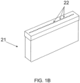
- System 10 comprises an additive manufacturing apparatus 14 having a dispensing unit 21 which comprises a plurality of dispensing heads. Each head preferably comprises an array of one or more nozzles 22, as illustrated in FIG. 1B , through which a liquid building material 24 is dispensed.
- the apparatus 14 is a three-dimensional printing apparatus, in which case the dispensing heads are printing heads, and the building material is dispensed via inkjet technology. This need not necessarily be the case, since, for some applications, it may not be necessary for the additive manufacturing apparatus to employ three-dimensional printing techniques.
- Each dispensing head is optionally and preferably fed via a building material reservoir which may optionally include a temperature control unit (e.g., a temperature sensor and/or a heating device), and a material level sensor.
- a temperature control unit e.g., a temperature sensor and/or a heating device
- a material level sensor e.g., a temperature sensor and/or a heating device
- a voltage signal is applied to the dispensing heads to selectively deposit droplets of material via the dispensing head nozzles, for example, as in piezoelectric inkjet printing technology.
- the dispensing rate of each head depends on the number of nozzles, the type of nozzles and the applied voltage signal rate (frequency).
- Such dispensing heads are known to those skilled in the art of solid freeform fabrication.
- the overall number of dispensing nozzles or nozzle arrays is selected such that half of the dispensing nozzles are designated to dispense support material and half of the dispensing nozzles are designated to dispense modeling material, i.e. the number of nozzles jetting modeling materials is the same as the number of nozzles jetting support material.
- four dispensing heads 21a, 21b, 21c and 21d are illustrated. Each of heads 21a, 21b, 21c and 21d has a nozzle array. In this Example, heads 21a and 21b can be designated for modeling material/s and heads 21c and 21d can be designated for support material.
- head 21a can dispense a first modeling material
- head 21b can dispense a second modeling material
- heads 21c and 21d can both dispense support material.
- heads 21c and 21d may be combined in a single head having two nozzle arrays for depositing support material.
- modeling material depositing heads modeling heads
- support heads support heads
- the number of modeling heads, the number of support heads and the number of nozzles in each respective head or head array are selected such as to provide a predetermined ratio, a , between the maximal dispensing rate of the support material and the maximal dispensing rate of modeling material.
- the value of the predetermined ratio, a is preferably selected to ensure that in each formed layer, the height of modeling material equals the height of support material. Typical values for a are from about 0.6 to about 1.5.
- the overall dispensing rate of support material is generally the same as the overall dispensing rate of the modeling material when all modeling heads and support heads operate.
- each of the M ⁇ m modeling arrays and S ⁇ s support arrays can be manufactured as a separate physical unit, which can be assembled and disassembled from the group of arrays.
- each such array optionally and preferably comprises a temperature control unit and a material level sensor of its own, and receives an individually controlled voltage for its operation.
- a control unit 52 controls fabrication apparatus 14 and optionally and preferably also supply apparatus 50.
- Control unit 52 preferably communicates with a data processor 54 which transmits digital data pertaining to fabrication instructions based on computer object data, e.g., a CAD configuration represented on a computer readable medium in a form of a Standard Tessellation Language (STL) format or the like.
- control unit 52 controls the voltage applied to each dispensing head or nozzle array and the temperature of the building material in the respective printing head.
- Any post deposition combination or mix of modeling materials is contemplated. For example, once a certain material is dispensed it may preserve its original properties. However, when it is dispensed simultaneously with another modeling material or other dispensed materials which are dispensed at the same or nearby locations, a composite material having a different property or properties to the dispensed materials is formed.
- control unit 52 receives HDT data which characterize the building material being used.
- the HDT data typically corresponds to the HDT that the material acquires once cured.
- Such data can be provided, for example, by the operator by means of data processor 54 or user interface 16. It is to be understood that it is not necessary for the operator to literally enter the HDT data (although this is also contemplated).
- control unit 52 or data processor 54 access a database of HDT values which can be stored in a memory medium (not shown) and select the HDT value based on other types of input made by the operator.
- a database can include a plurality of entries each having a building material type and a corresponding HDT value.
- control unit 52 or data processor 54 obtains the respective HDT value from the database. Also contemplated are embodiments in which the control unit 52 or data processor 54 obtains the respective HDT value from the database based on the type(s) of building materials loaded into supply apparatus 50.
- control unit 52 receives the HDT data it optionally selects the value of t responsively to the HDT. This can be done in more than one way.
- a lookup table is used. Such a lookup table can be stored in a memory medium accessible by unit 52.
- the lookup table can include a plurality of entries each having an HDT value and a corresponding t value.
- Control unit 52 can search the table for an entry that best matches the received HDT value and select the respective t value or approximate the t value based on the best matched entry or entries.
- control unit 52 can employ a preprogrammed function t (HDT) for determining the value of t for a given value of HDT.
- Such function is preferably a monotonically increasing function (e.g., a linear function having a positive slope) of HDT.
- control unit 52 selects the value of t directly from the type of building material being used for manufacturing the object. This is typically performed by a lookup table which in some embodiments of the present invention is stored in a memory medium accessible by unit 52.
- a lookup table can include a plurality of entries each having a building material type or a building material family type and a corresponding t value.
- Control unit 52 can search the table for an entry that best matches the type of building material or the family type of the building material, and select the respective t value.
- the value of t is also based on the operational temperature of the manufacturing process, preferably, but not necessarily, on the difference between the HDT value and the operational temperature.
- the value of t can optionally and preferably be based, at least in part on the energy dose delivered to the most recently formed layer.
- the energy dose per unit volume depends, in principle, on the intensity of the radiation emitted by curing unit 26, and on the rate at which the material is dispensed.
- the dispensing rate in turn, depends on the speed of block 28 along the X direction and on the flow of building material out of nozzles 22. For example, for a given modeling material, a given flow of building material out of nozzles 22 and a given radiation intensity, the speed of block 28 moving along the X direction results in a lower polymerization extent per layer in the formation process, with the layers continuing to polymerize during the curing of subsequent layers above them. It was found by the present inventors that such polymerization of previously formed layers increases the curling effect.
- the value of t is calculated based on one or more of the following parameters: (i) layer thickness, (ii) dispensing rate, (iii) radiation intensity, (iv) polymerization rate per unit energy dose, and (v) the HDT of the material being cured.
- the value of t is calculated based on at least two of the above parameters, in some embodiments of the present invention the value of t is calculated based on at least three of the above parameters, and in some embodiments of the present invention the value of t is calculated based on all the above parameters.
- a method suitable for additive manufacturing of a three-dimensional object can be executed using an AM system, e.g., system 10.
- the method comprises sequentially forming a plurality of layers in a configured pattern corresponding to the shape of the object.
- the formation of each layer comprises dispensing of at least one building material to form an uncured layer, and at least partially curing of the uncured layer.
- the curing is initiated at least t seconds after the commencement of the curing of a layer immediately preceding the respective layer as further detailed hereinabove.
- the method receives characteristic HDT data of at least one of the building materials, and selects a value of t responsively to HDT, as further detailed hereinabove. In some embodiments, the value of t is selected based on the HDT of the building material.
- the method and system of the present embodiments can utilize many types of building materials.
- Representative examples include, without limitation, building materials for which the post curing HDT at a pressure of about 0.45 MPa, as measured by one or more of the ASTM D-648 series of procedures, particularly the ASTM D-648-06 and ASTM D-648-07 methods, and optionally both the ASTM D-648-06 and ASTM D-648-07 methods, is higher than the temperature of layers while being formed, preferably HDT about 50 °C or higher.
- Suitable building materials can include compositions which comprise acrylic or methacrylic functionalities, which are UV polymerizable by radical mechanism, e.g., the addition reaction of acrylic functional groups. Further examples include, without limitation, UV polymerizable compositions that comprise at least 30 % by weight of a mono acrylic or mono methacrylic functional monomer, wherein the respective polymer of the monomer has a Glass Transition Temperature (Tg) higher than about 50 °C. In some embodiment, Tg is higher than 60°C or higher than 70°C.
- Tg Glass Transition Temperature
- Tg refers to glass transition temperature defined as the location of the local maximum of the E" curve, where E" is the loss modulus of the material as a function of the temperature.
- Some representative types of materials suitable for the present embodiments include Objet ® VeroBlue RGD840, Objet ® VeroGrey RGD850, Objet ® VeroBlack RGD870 and Objet ® RGD525 which are commercially available modeling materials of Objet Ltd.
- compositions, method or structure may include additional ingredients, steps and/or parts, but only if the additional ingredients, steps and/or parts do not materially alter the basic and novel characteristics of the claimed composition, method or structure.
- a compound or “at least one compound” may include a plurality of compounds, including mixtures thereof.
- range format is merely for convenience and brevity and should not be construed as an inflexible limitation on the scope of the invention. Accordingly, the description of a range should be considered to have specifically disclosed all the possible subranges as well as individual numerical values within that range. For example, description of a range such as from 1 to 6 should be considered to have specifically disclosed subranges such as from 1 to 3, from 1 to 4, from 1 to 5, from 2 to 4, from 2 to 6, from 3 to 6 etc., as well as individual numbers within that range, for example, 1, 2, 3, 4, 5, and 6. This applies regardless of the breadth of the range.
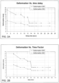
- time delays in seconds between successive curing processes were employed: 0, 5, 8, 10, 12, 13, 14, 15, 17, 20 and 25. These time values indicate durations for which the printing head was waiting before the next layer was deposited and cured.
- the curling was measured using a load e.g. of 300 gr weight on one side of the bar (on the horizontal surface), and on the other side measuring the vertical distance of the bar from the horizontal surface.
- the deformation was measured 24-48 hours after printing.
- the total printing time was measured.
- a time factor was calculated with respect to a reference printing process in which the printing head moves 1 pass per layer without delay between successive layers (first entry in Table 2, below).
- Table 1 Delay time [seconds] Average Deformation [mm] (250mm bar) Average Deformation [mm] (350mm bar) Total printing time [hrs] Time factor 0 6.5 12.8 0:58 1.0 5 5 10.0 1:54 2.0 8 5 10.0 2:27 2.5 10 4 8.5 2:58 3.1 12 4 8.5 3:17 3.4 13 3.25 5.0 3:31 3.6 14 3.25 5.0 3:45 3.9 15 3.25 5.0 3:58 4.1 17 3.25 5.0 4:19 4.5 20 3.25 5.0 5:01 5.2 25 3.25 5.0 6:04 6.3
- Table 1 and FIGs. 2A-B demonstrate that employing a delay time between successive layer formations significantly reduces the curling effect.
- the minimal delay time for achieving maximal reduction was 13 seconds which prolonged the overall printing time by a factor of about 3.6.
- High printing speed mode refers to the length of time to complete the printing of the object being shorter, i.e. 'speedier' than in a normal mode.
- High quality mode refers to a higher printing resolution of the object.
- Table 2 High Printing Speed Delay time [seconds] Deformation mm 23cm total printing time [min] time factor 0 10.5 33 1.0 10 7.5 75 2.3 12 6.5 91 2.8 15 6 108 3.3 18 5 129 3.9 20 5 142 4.3 23 5 161 4.9 28 5 192 5.8 Table 3 High Quality Mode Delay time [seconds] Deformation mm 23cm total printing time [min] time factor 0 6.5 58 1.0 8 5 114 2.0 11 5 147 2.5 13 4 178 3.1 15 4 197 3.4 16 3.25 211 3.6 17 3.25 225 3.9 18 3.25 238 4.1 20 3.25 259 4.5 23 3.25 301 5.2 28 3.25 364 6.3
- Tables 2 and 3, and FIG. 3 demonstrate that employing a delay time between successive layer formations significantly reduces the curling effect.
- the minimal delay time for achieving maximal reduction was 18 seconds for the high speed mode, and 16 seconds for the high quality mode. These minimal delay times prolonged the overall printing time by factors of about 3.9 and about 3.6, respectively.
Landscapes
- Chemical & Material Sciences (AREA)
- Engineering & Computer Science (AREA)
- Materials Engineering (AREA)
- Manufacturing & Machinery (AREA)
- Physics & Mathematics (AREA)
- Mechanical Engineering (AREA)
- Optics & Photonics (AREA)
Claims (13)
- Ein Verfahren zur additiven Fertigung eines dreidimensionalen Objekts, bei dem, in einem der Form des Objekts entsprechenden ausgebildeten Muster, nacheinander mehrere Schichten übereinander ausgebildet werden, wodurch das Objekt gebildet wird;wobei die Bildung jeder Schicht, zum Ausgeben zumindest eines ungehärteten Baumaterials durch Tintenstrahltechnologie, das Betreiben eines Ausgabekopfes und, zum zumindest teilweisen Aushärten des ungehärteten Baumaterials, das Betreiben einer Strahlungsquelle umfasst, undwobei der Ausgabekopf und die Strahlungsquelle auf einem sich hin- und herbewegenden Block montiert sind;dadurch gekennzeichnet, dass das Verfahren umfasst: Bewegen des Blockes in einem Durchgang über die Ablage, um eine einzelne Schicht des Baumaterials auszugeben und auszuhärten, Versetzen des Blocks in eine Ruheposition zum Ruhen für eine Ruhezeit, welche einer oder mehreren, dem Durchgang des Blocks über eine Ablage entsprechenden Zeitabschnitten entspricht, um sicherzustellen, dass das Aushärten einer nachfolgenden Schicht zumindest t Sekunden nach Beginn des Aushärtens der einzelnen Schicht eingeleitet wird, wobei t länger ist als eine für die Bildung erforderliche Gesamtzeit, wobei die Ruhezeit eine Differenz zwischen der Gesamtbildungszeit und t darstellt.
- Das Verfahren nach Anspruch 1, welches ferner das Auswählen eines Wertes für t auf der Grundlage eines Typs des zumindest einen Baumaterials umfasst.
- Das Verfahren nach einem der Ansprüche 1 und 2, welches ferner das Auswählen eines Wertes für t auf der Grundlage der während des Aushärtens an die zumindest eine Schicht abgegebenen Energiedosis pro Volumeneinheit umfasst.
- Das Verfahren nach einem der Ansprüche 1 bis 3, welches ferner das Auswählen eines Wertes für t auf der Grundlage einer Dicke der zumindest einen Schicht umfasst.
- Das Verfahren nach einem der Ansprüche 1 bis 4, welches ferner das Auswählen eines Wertes für t auf der Grundlage einer die Ausgabe der zumindest einen Schicht charakterisierenden Rate umfasst.
- Das Verfahren nach einem der Ansprüche 1 bis 5, wobei das Baumaterial zumindest 30 Gew.-% eines monoacrylischen oder monomethacrylischen funktionellen Monomers aufweist und ein entsprechendes Polymer des Monomers eine Glasübergangstemperatur (Tg) von mehr als 50 °C aufweist.
- Das Verfahren nach Anspruch 6, wobei die Tg über 60 °C beträgt.
- Ein Computersoftwareprodukt, das ein computerlesbares Medium aufweist, in dem Programmanweisungen gespeichert sind, wobei die Anweisungen, wenn sie von einer computerisierten Steuerung eines additiven Fertigungssystems gelesen werden, das System veranlassen, das Verfahren nach einem der Ansprüche 1 bis 7 auszuführen.
- Ein System (10) zur additiven Fertigung eines dreidimensionalen Objekts (12), aufweisend:eine Ausgabeeinheit (21), ausgebildet, um durch Tintenstrahltechnologie zumindest eine Art ungehärteten Baumaterials auszugeben;eine Aushärtungseinheit (26), ausgebildet, um das ungehärtete Baumaterial auszuhärten;eine Steuerung (52), ausgebildet, um die Ausgabeeinheit (21) und die Aushärtungseinheit (26) zu betätigen, um nacheinander eine Mehrzahl an übereinander liegende Schichten in einem der Form des dreidimensionalen Objekts (12) entsprechenden ausgebildeten Muster zu bilden; undeinen hin- und her bewegbaren Block (28), wobei die Ausgabeeinheit (21) und die Aushärtungseinheit (26) an diesem Block (28) angebracht sind;dadurch gekennzeichnet, dass
die Steuerung (52) konfiguriert ist, um: zu signalisieren, dass sich der Block (28) in einem Durchgang über die Ablage (30) bewegt, um eine einzelne Schicht des Baumaterials auszugeben und auszuhärten, den Block (28) in eine Ruheposition zu versetzen, für eine Ruhezeit, die einer oder mehreren dem Durchgang des Blocks über eine Ablage (30) entsprechenden Zeitabschnitten entspricht, um sicherzustellen, dass das Aushärten einer nachfolgenden Schicht zumindest t Sekunden nach Beginn des Aushärtens einer der einzelnen Schicht unmittelbar vorangegangenen Schicht eingeleitet wird, wobei t länger ist als eine für das Ausgeben und das Aushärten der einzelnen Schicht erforderliche Gesamtzeit, und wobei die Ruhezeit eine Differenz zwischen der Gesamtbildungszeit und t darstellt. - Das System (10) nach Anspruch 9, wobei die Steuerung (52) so ausgebildet ist, dass sie einen Wert für t auf der Grundlage eines Typs des zumindest einen Baumaterials auswählt.
- Das System (10) nach einem der Ansprüche 9 und 10, wobei die Steuerung (52) so ausgebildet ist, dass sie einen Wert für t auf der Grundlage der während des Aushärtens an die zumindest eine Schicht abgegebene Energiedosis pro Volumeneinheit auswählt.
- Das System (10) nach einem der Ansprüche 9 bis 11, wobei die Steuerung (52) so ausgebildet ist, dass sie einen Wert für t auf der Grundlage einer Dicke der zumindest einen Schicht auswählt.
- Das System (10) nach einem der Ansprüche 9 bis 12, wobei die Steuerung (52) so ausgebildet ist, dass sie einen Wert für t auf der Grundlage einer das Ausgeben der zumindest einen Schicht charakterisierenden Rate auswählt.
Applications Claiming Priority (3)
| Application Number | Priority Date | Filing Date | Title |
|---|---|---|---|
| US41743810P | 2010-11-28 | 2010-11-28 | |
| PCT/IL2011/050032 WO2012070053A1 (en) | 2010-11-28 | 2011-11-28 | System and method for additive manufacturing of an object |
| EP11808366.6A EP2643149B1 (de) | 2010-11-28 | 2011-11-28 | System und verfahren zur generativen herstellung eines objekts |
Related Parent Applications (2)
| Application Number | Title | Priority Date | Filing Date |
|---|---|---|---|
| EP11808366.6A Division EP2643149B1 (de) | 2010-11-28 | 2011-11-28 | System und verfahren zur generativen herstellung eines objekts |
| EP11808366.6A Division-Into EP2643149B1 (de) | 2010-11-28 | 2011-11-28 | System und verfahren zur generativen herstellung eines objekts |
Publications (2)
| Publication Number | Publication Date |
|---|---|
| EP3034282A1 EP3034282A1 (de) | 2016-06-22 |
| EP3034282B1 true EP3034282B1 (de) | 2025-04-16 |
Family
ID=45478416
Family Applications (2)
| Application Number | Title | Priority Date | Filing Date |
|---|---|---|---|
| EP16155427.4A Active EP3034282B1 (de) | 2010-11-28 | 2011-11-28 | System und verfahren zur generativen herstellung eines objekts |
| EP11808366.6A Active EP2643149B1 (de) | 2010-11-28 | 2011-11-28 | System und verfahren zur generativen herstellung eines objekts |
Family Applications After (1)
| Application Number | Title | Priority Date | Filing Date |
|---|---|---|---|
| EP11808366.6A Active EP2643149B1 (de) | 2010-11-28 | 2011-11-28 | System und verfahren zur generativen herstellung eines objekts |
Country Status (7)
| Country | Link |
|---|---|
| US (2) | US10105903B2 (de) |
| EP (2) | EP3034282B1 (de) |
| JP (1) | JP5956455B2 (de) |
| CN (2) | CN103384591A (de) |
| HK (1) | HK1219704A1 (de) |
| IL (2) | IL226623A (de) |
| WO (1) | WO2012070053A1 (de) |
Families Citing this family (35)
| Publication number | Priority date | Publication date | Assignee | Title |
|---|---|---|---|---|
| WO2012070053A1 (en) | 2010-11-28 | 2012-05-31 | Objet Ltd. | System and method for additive manufacturing of an object |
| JP6335782B2 (ja) | 2011-07-13 | 2018-05-30 | ヌボトロニクス、インク. | 電子的および機械的な構造を製作する方法 |
| US10150247B2 (en) | 2013-03-12 | 2018-12-11 | Orange Maker LLC | 3D printing using spiral buildup and high viscosity build materials |
| JP6456353B2 (ja) * | 2013-03-12 | 2019-01-23 | オレンジ・メーカー・エルエルシー | 渦巻状の積上げを使用した3d印刷 |
| CA2937969C (en) * | 2013-12-31 | 2023-10-03 | Dentsply International Inc. | Dental compositions containing upconversion phosphors and methods of use |
| WO2015108546A2 (en) | 2014-01-16 | 2015-07-23 | Hewlett-Packard Development Company, L.P. | Generating three-dimensional objects |
| JP6570542B2 (ja) | 2014-01-16 | 2019-09-04 | ヒューレット−パッカード デベロップメント カンパニー エル.ピー.Hewlett‐Packard Development Company, L.P. | 三次元物体の生成 |
| EP3626434B1 (de) * | 2014-01-16 | 2025-08-06 | Peridot Print LLC | Erzeugen eines dreidimensionalen objekts |
| CN105939836B (zh) | 2014-01-16 | 2018-05-01 | 惠普发展公司,有限责任合伙企业 | 构造材料简档 |
| EP3105040B1 (de) * | 2014-02-10 | 2023-10-18 | Stratasys Ltd. | Zusammensetzung und verfahren zur additiven fertigung eines objekts |
| TWI556946B (zh) * | 2014-03-07 | 2016-11-11 | 三緯國際立體列印科技股份有限公司 | 立體列印裝置及其列印頭控制方法 |
| JP6503375B2 (ja) | 2014-05-08 | 2019-04-17 | ストラタシス リミテッド | 選択的焼結による3d印刷のための方法及び装置 |
| SE537864C2 (sv) * | 2014-05-14 | 2015-11-03 | Katarina Gustafsson | En metod och en apparat för geometrisk verifiering vid additiv tillverkning av tredimensionella objekt |
| JP6428049B2 (ja) * | 2014-08-25 | 2018-11-28 | 富士ゼロックス株式会社 | 積層造形装置及び積層造形プログラム |
| JP6590473B2 (ja) * | 2014-09-24 | 2019-10-16 | 株式会社ミマキエンジニアリング | 立体物造形装置及び立体物造形方法 |
| US9742137B2 (en) * | 2014-12-08 | 2017-08-22 | Nkt Hv Cables Gmbh | Method for automated splicing and terminating low, medium, high, and extra high voltage cables |
| CN113325664B (zh) | 2014-12-23 | 2024-07-19 | 普利司通美国轮胎运营有限责任公司 | 聚合物产品的增材制造方法 |
| US10144185B2 (en) * | 2015-04-01 | 2018-12-04 | The Boeing Company | Method and apparatus for high-temperature post-curing of UV-cured photopolymers |
| CN104890249B (zh) * | 2015-07-07 | 2017-03-29 | 杭州先临三维科技股份有限公司 | 一种具有多喷嘴的 3d 打印装置及其打印方法 |
| FI129702B (en) | 2015-10-09 | 2022-07-15 | Inkron Ltd | Three dimensional printing materials and method for making a 3D printed article |
| EP3390006B1 (de) | 2015-12-17 | 2021-01-27 | Bridgestone Americas Tire Operations, LLC | Kartuschen zur generativen fertigung und verfahren zur herstellung gehärteter polymerprodukte durch generative fertigung |
| KR102334945B1 (ko) | 2016-04-11 | 2021-12-06 | 스트라타시스 엘티디. | 분말 재료의 적층 가공을 위한 방법 및 장치 |
| JP6719961B2 (ja) * | 2016-04-27 | 2020-07-08 | 株式会社ミマキエンジニアリング | 造形装置及び造形方法 |
| US11235531B2 (en) | 2016-05-12 | 2022-02-01 | Hewlett-Packard Development Company, L.P. | Selecting a task in additive manufacturing |
| WO2018081053A1 (en) | 2016-10-27 | 2018-05-03 | Bridgestone Americas Tire Operations, Llc | Processes for producing cured polymeric products by additive manufacturing |
| CN108327253B (zh) * | 2017-01-19 | 2021-08-06 | 上海普利生机电科技有限公司 | 光固化型三维打印方法和设备 |
| IL269485B2 (en) | 2017-03-20 | 2024-03-01 | Stratasys Ltd | Method and system for additive manufacturing with powder material |
| JP6822881B2 (ja) | 2017-03-27 | 2021-01-27 | 株式会社神戸製鋼所 | 積層造形物の製造方法及び製造システム |
| EP4275868B1 (de) | 2018-09-27 | 2025-07-02 | Stratasys Ltd. | Verfahren und system zur generativen fertigung |
| WO2020065654A1 (en) * | 2018-09-28 | 2020-04-02 | Stratasys Ltd. | Method for additive manufacturing with partial curing |
| JP2020124828A (ja) * | 2019-02-04 | 2020-08-20 | 株式会社ミマキエンジニアリング | 立体物製造システムおよび立体物製造管理プログラム |
| US11619039B2 (en) * | 2020-03-05 | 2023-04-04 | Mighty Buildings, Inc. | Three-dimensional printed building components and structures |
| CN116670366A (zh) * | 2020-10-02 | 2023-08-29 | 建筑机械股份有限公司 | 使用可调整模板进行增材制造的系统和方法 |
| EP4094942A1 (de) | 2021-05-26 | 2022-11-30 | TIGER Coatings GmbH & Co. KG | Strahlungshärtbare zusammensetzung zur generativen fertigung für elektronische anwendungen |
| US12246484B2 (en) * | 2022-02-25 | 2025-03-11 | Textron Innovations Inc. | Break-wire conductor manufacturing methods |
Citations (1)
| Publication number | Priority date | Publication date | Assignee | Title |
|---|---|---|---|---|
| US20090304952A1 (en) * | 2008-06-05 | 2009-12-10 | Kritchman Eliahu M | Apparatus and method for solid freeform fabrication |
Family Cites Families (21)
| Publication number | Priority date | Publication date | Assignee | Title |
|---|---|---|---|---|
| US4863648A (en) * | 1986-07-03 | 1989-09-05 | Rutgers, The State University Of New Jersey | Process for making polarized material |
| US5965079A (en) * | 1995-04-25 | 1999-10-12 | 3D Systems, Inc. | Method and apparatus for making a three-dimensional object by stereolithography |
| US5184307A (en) * | 1988-04-18 | 1993-02-02 | 3D Systems, Inc. | Method and apparatus for production of high resolution three-dimensional objects by stereolithography |
| US6399010B1 (en) * | 1999-02-08 | 2002-06-04 | 3D Systems, Inc. | Method and apparatus for stereolithographically forming three dimensional objects with reduced distortion |
| US6259962B1 (en) | 1999-03-01 | 2001-07-10 | Objet Geometries Ltd. | Apparatus and method for three dimensional model printing |
| US6658314B1 (en) | 1999-10-06 | 2003-12-02 | Objet Geometries Ltd. | System and method for three dimensional model printing |
| US6850334B1 (en) | 2000-01-18 | 2005-02-01 | Objet Geometries Ltd | System and method for three dimensional model printing |
| US7300619B2 (en) | 2000-03-13 | 2007-11-27 | Objet Geometries Ltd. | Compositions and methods for use in three dimensional model printing |
| US6569373B2 (en) | 2000-03-13 | 2003-05-27 | Object Geometries Ltd. | Compositions and methods for use in three dimensional model printing |
| US20030207959A1 (en) | 2000-03-13 | 2003-11-06 | Eduardo Napadensky | Compositions and methods for use in three dimensional model printing |
| US6813594B2 (en) * | 2001-05-03 | 2004-11-02 | 3D Systems, Inc. | Automatic determination and selection of build parameters for solid freeform fabrication techniques based on automatic part feature recognition |
| US6699424B2 (en) | 2001-06-29 | 2004-03-02 | 3D Systems, Inc. | Method for forming three-dimensional objects |
| US6706234B2 (en) * | 2001-08-08 | 2004-03-16 | Nanotek Instruments, Inc. | Direct write method for polarized materials |
| US20030151167A1 (en) | 2002-01-03 | 2003-08-14 | Kritchman Eliahu M. | Device, system and method for accurate printing of three dimensional objects |
| AU2003286397A1 (en) | 2002-12-03 | 2004-06-23 | Objet Geometries Ltd. | Process of and apparatus for three-dimensional printing |
| DE602004008458T2 (de) | 2003-05-01 | 2008-05-21 | Objet Geometries Ltd. | Rapid-prototyping-vorrichtung |
| JP5111880B2 (ja) | 2007-02-02 | 2013-01-09 | シーメット株式会社 | 面露光による光学的立体造形用樹脂組成物 |
| US8784723B2 (en) * | 2007-04-01 | 2014-07-22 | Stratasys Ltd. | Method and system for three-dimensional fabrication |
| EP2664443B1 (de) | 2007-07-25 | 2021-08-25 | Stratasys Ltd. | Feste Freiformproduktion unter Verwendung mehrerer Modelliermaterialien |
| US7962237B2 (en) | 2008-08-06 | 2011-06-14 | Objet Geometries Ltd. | Method and apparatus for optimizing a scanning plan in three-dimensional printing |
| WO2012070053A1 (en) | 2010-11-28 | 2012-05-31 | Objet Ltd. | System and method for additive manufacturing of an object |
-
2011
- 2011-11-28 WO PCT/IL2011/050032 patent/WO2012070053A1/en not_active Ceased
- 2011-11-28 EP EP16155427.4A patent/EP3034282B1/de active Active
- 2011-11-28 EP EP11808366.6A patent/EP2643149B1/de active Active
- 2011-11-28 US US13/989,826 patent/US10105903B2/en active Active
- 2011-11-28 JP JP2013540490A patent/JP5956455B2/ja active Active
- 2011-11-28 CN CN2011800571479A patent/CN103384591A/zh active Pending
- 2011-11-28 CN CN201610633309.3A patent/CN106564186B/zh not_active Expired - Fee Related
-
2013
- 2013-05-28 IL IL226623A patent/IL226623A/en active IP Right Grant
-
2016
- 2016-07-05 HK HK16107801.6A patent/HK1219704A1/en unknown
- 2016-09-11 IL IL247758A patent/IL247758B/en active IP Right Grant
-
2018
- 2018-10-22 US US16/166,228 patent/US10688715B2/en active Active
Patent Citations (1)
| Publication number | Priority date | Publication date | Assignee | Title |
|---|---|---|---|---|
| US20090304952A1 (en) * | 2008-06-05 | 2009-12-10 | Kritchman Eliahu M | Apparatus and method for solid freeform fabrication |
Also Published As
| Publication number | Publication date |
|---|---|
| JP2014503385A (ja) | 2014-02-13 |
| WO2012070053A1 (en) | 2012-05-31 |
| IL247758A0 (en) | 2016-11-30 |
| JP5956455B2 (ja) | 2016-07-27 |
| EP2643149A1 (de) | 2013-10-02 |
| CN106564186B (zh) | 2020-07-28 |
| IL226623A (en) | 2016-09-29 |
| IL247758B (en) | 2019-09-26 |
| CN106564186A (zh) | 2017-04-19 |
| US20190054683A1 (en) | 2019-02-21 |
| HK1219704A1 (en) | 2017-04-13 |
| US10688715B2 (en) | 2020-06-23 |
| CN103384591A (zh) | 2013-11-06 |
| US20140110872A1 (en) | 2014-04-24 |
| EP3034282A1 (de) | 2016-06-22 |
| EP2643149B1 (de) | 2016-04-20 |
| US10105903B2 (en) | 2018-10-23 |
Similar Documents
| Publication | Publication Date | Title |
|---|---|---|
| US10688715B2 (en) | System and method for additive manufacturing of an object | |
| US11872766B2 (en) | System and method for additive manufacturing of an object | |
| US10828825B2 (en) | System and method for depositing liquids | |
| EP2643148A1 (de) | System und verfahren zur herstellung von zusatzstoffen eines objekts | |
| US20220080671A1 (en) | Method and system for controlling a cooling system in three-dimensional printing | |
| EP3814102B1 (de) | Verfahren und system zur reduzierung der kräuselung in der generativen fertigung | |
| HK1236892A1 (en) | System and method for additive manufacturing of an object | |
| HK1236892B (zh) | 用於对象的加式制造的系统和方法 | |
| EP3906147A1 (de) | Verfahren und system zur verbesserung der farbgleichmässigkeit beim tintenstrahldruck | |
| HK1190118A (en) | System and method for additive manufacturing of an object | |
| HK1259435A1 (en) | System and computer product for additive manufacturing of an object | |
| HK1259435B (en) | System and computer product for additive manufacturing of an object | |
| HK1223332B (en) | System and method for additive manufacturing of an object | |
| HK1190117B (en) | System and method for additive manufacturing of an object |
Legal Events
| Date | Code | Title | Description |
|---|---|---|---|
| PUAI | Public reference made under article 153(3) epc to a published international application that has entered the european phase |
Free format text: ORIGINAL CODE: 0009012 |
|
| 17P | Request for examination filed |
Effective date: 20160212 |
|
| AC | Divisional application: reference to earlier application |
Ref document number: 2643149 Country of ref document: EP Kind code of ref document: P |
|
| AK | Designated contracting states |
Kind code of ref document: A1 Designated state(s): AL AT BE BG CH CY CZ DE DK EE ES FI FR GB GR HR HU IE IS IT LI LT LU LV MC MK MT NL NO PL PT RO RS SE SI SK SM TR |
|
| REG | Reference to a national code |
Ref country code: HK Ref legal event code: DE Ref document number: 1219704 Country of ref document: HK |
|
| STAA | Information on the status of an ep patent application or granted ep patent |
Free format text: STATUS: EXAMINATION IS IN PROGRESS |
|
| 17Q | First examination report despatched |
Effective date: 20191029 |
|
| P01 | Opt-out of the competence of the unified patent court (upc) registered |
Effective date: 20230719 |
|
| REG | Reference to a national code |
Ref country code: DE Ref legal event code: R079 Ref document number: 602011075302 Country of ref document: DE Free format text: PREVIOUS MAIN CLASS: B29C0067000000 Ipc: B29C0064124000 Ref country code: DE Ref legal event code: R079 Free format text: PREVIOUS MAIN CLASS: B29C0067000000 Ipc: B29C0064124000 |
|
| RIC1 | Information provided on ipc code assigned before grant |
Ipc: B33Y 10/00 20150101ALI20241005BHEP Ipc: B33Y 30/00 20150101ALI20241005BHEP Ipc: B29C 64/188 20170101ALI20241005BHEP Ipc: B29C 64/112 20170101ALI20241005BHEP Ipc: B29C 64/393 20170101ALI20241005BHEP Ipc: B29C 64/124 20170101AFI20241005BHEP |
|
| GRAP | Despatch of communication of intention to grant a patent |
Free format text: ORIGINAL CODE: EPIDOSNIGR1 |
|
| STAA | Information on the status of an ep patent application or granted ep patent |
Free format text: STATUS: GRANT OF PATENT IS INTENDED |
|
| INTG | Intention to grant announced |
Effective date: 20241125 |
|
| GRAS | Grant fee paid |
Free format text: ORIGINAL CODE: EPIDOSNIGR3 |
|
| GRAA | (expected) grant |
Free format text: ORIGINAL CODE: 0009210 |
|
| STAA | Information on the status of an ep patent application or granted ep patent |
Free format text: STATUS: THE PATENT HAS BEEN GRANTED |
|
| AC | Divisional application: reference to earlier application |
Ref document number: 2643149 Country of ref document: EP Kind code of ref document: P |
|
| AK | Designated contracting states |
Kind code of ref document: B1 Designated state(s): AL AT BE BG CH CY CZ DE DK EE ES FI FR GB GR HR HU IE IS IT LI LT LU LV MC MK MT NL NO PL PT RO RS SE SI SK SM TR |
|
| REG | Reference to a national code |
Ref country code: GB Ref legal event code: FG4D |
|
| REG | Reference to a national code |
Ref country code: CH Ref legal event code: EP Ref country code: DE Ref legal event code: R096 Ref document number: 602011075302 Country of ref document: DE |
|
| REG | Reference to a national code |
Ref country code: IE Ref legal event code: FG4D |
|
| REG | Reference to a national code |
Ref country code: HK Ref legal event code: WD Ref document number: 1219704 Country of ref document: HK |
|
| REG | Reference to a national code |
Ref country code: NL Ref legal event code: MP Effective date: 20250416 |
|
| PG25 | Lapsed in a contracting state [announced via postgrant information from national office to epo] |
Ref country code: NL Free format text: LAPSE BECAUSE OF FAILURE TO SUBMIT A TRANSLATION OF THE DESCRIPTION OR TO PAY THE FEE WITHIN THE PRESCRIBED TIME-LIMIT Effective date: 20250416 |
|
| REG | Reference to a national code |
Ref country code: AT Ref legal event code: MK05 Ref document number: 1785299 Country of ref document: AT Kind code of ref document: T Effective date: 20250416 |
|
| PG25 | Lapsed in a contracting state [announced via postgrant information from national office to epo] |
Ref country code: FI Free format text: LAPSE BECAUSE OF FAILURE TO SUBMIT A TRANSLATION OF THE DESCRIPTION OR TO PAY THE FEE WITHIN THE PRESCRIBED TIME-LIMIT Effective date: 20250416 Ref country code: ES Free format text: LAPSE BECAUSE OF FAILURE TO SUBMIT A TRANSLATION OF THE DESCRIPTION OR TO PAY THE FEE WITHIN THE PRESCRIBED TIME-LIMIT Effective date: 20250416 Ref country code: PT Free format text: LAPSE BECAUSE OF FAILURE TO SUBMIT A TRANSLATION OF THE DESCRIPTION OR TO PAY THE FEE WITHIN THE PRESCRIBED TIME-LIMIT Effective date: 20250818 |
|
| REG | Reference to a national code |
Ref country code: LT Ref legal event code: MG9D |
|
| PG25 | Lapsed in a contracting state [announced via postgrant information from national office to epo] |
Ref country code: GR Free format text: LAPSE BECAUSE OF FAILURE TO SUBMIT A TRANSLATION OF THE DESCRIPTION OR TO PAY THE FEE WITHIN THE PRESCRIBED TIME-LIMIT Effective date: 20250717 Ref country code: NO Free format text: LAPSE BECAUSE OF FAILURE TO SUBMIT A TRANSLATION OF THE DESCRIPTION OR TO PAY THE FEE WITHIN THE PRESCRIBED TIME-LIMIT Effective date: 20250716 |
|
| PG25 | Lapsed in a contracting state [announced via postgrant information from national office to epo] |
Ref country code: PL Free format text: LAPSE BECAUSE OF FAILURE TO SUBMIT A TRANSLATION OF THE DESCRIPTION OR TO PAY THE FEE WITHIN THE PRESCRIBED TIME-LIMIT Effective date: 20250416 |
|
| PG25 | Lapsed in a contracting state [announced via postgrant information from national office to epo] |
Ref country code: BG Free format text: LAPSE BECAUSE OF FAILURE TO SUBMIT A TRANSLATION OF THE DESCRIPTION OR TO PAY THE FEE WITHIN THE PRESCRIBED TIME-LIMIT Effective date: 20250416 |
|
| PG25 | Lapsed in a contracting state [announced via postgrant information from national office to epo] |
Ref country code: HR Free format text: LAPSE BECAUSE OF FAILURE TO SUBMIT A TRANSLATION OF THE DESCRIPTION OR TO PAY THE FEE WITHIN THE PRESCRIBED TIME-LIMIT Effective date: 20250416 |
|
| PG25 | Lapsed in a contracting state [announced via postgrant information from national office to epo] |
Ref country code: AT Free format text: LAPSE BECAUSE OF FAILURE TO SUBMIT A TRANSLATION OF THE DESCRIPTION OR TO PAY THE FEE WITHIN THE PRESCRIBED TIME-LIMIT Effective date: 20250416 |
|
| PG25 | Lapsed in a contracting state [announced via postgrant information from national office to epo] |
Ref country code: RS Free format text: LAPSE BECAUSE OF FAILURE TO SUBMIT A TRANSLATION OF THE DESCRIPTION OR TO PAY THE FEE WITHIN THE PRESCRIBED TIME-LIMIT Effective date: 20250716 |
|
| PG25 | Lapsed in a contracting state [announced via postgrant information from national office to epo] |
Ref country code: IS Free format text: LAPSE BECAUSE OF FAILURE TO SUBMIT A TRANSLATION OF THE DESCRIPTION OR TO PAY THE FEE WITHIN THE PRESCRIBED TIME-LIMIT Effective date: 20250816 |
|
| PG25 | Lapsed in a contracting state [announced via postgrant information from national office to epo] |
Ref country code: LV Free format text: LAPSE BECAUSE OF FAILURE TO SUBMIT A TRANSLATION OF THE DESCRIPTION OR TO PAY THE FEE WITHIN THE PRESCRIBED TIME-LIMIT Effective date: 20250416 |
|
| PGFP | Annual fee paid to national office [announced via postgrant information from national office to epo] |
Ref country code: DE Payment date: 20251022 Year of fee payment: 15 |
|
| PGFP | Annual fee paid to national office [announced via postgrant information from national office to epo] |
Ref country code: GB Payment date: 20251023 Year of fee payment: 15 |
|
| PG25 | Lapsed in a contracting state [announced via postgrant information from national office to epo] |
Ref country code: DK Free format text: LAPSE BECAUSE OF FAILURE TO SUBMIT A TRANSLATION OF THE DESCRIPTION OR TO PAY THE FEE WITHIN THE PRESCRIBED TIME-LIMIT Effective date: 20250416 Ref country code: SM Free format text: LAPSE BECAUSE OF FAILURE TO SUBMIT A TRANSLATION OF THE DESCRIPTION OR TO PAY THE FEE WITHIN THE PRESCRIBED TIME-LIMIT Effective date: 20250416 |
|
| PGFP | Annual fee paid to national office [announced via postgrant information from national office to epo] |
Ref country code: FR Payment date: 20251022 Year of fee payment: 15 |
|
| REG | Reference to a national code |
Ref country code: DE Ref legal event code: R097 Ref document number: 602011075302 Country of ref document: DE |
|
| PG25 | Lapsed in a contracting state [announced via postgrant information from national office to epo] |
Ref country code: CZ Free format text: LAPSE BECAUSE OF FAILURE TO SUBMIT A TRANSLATION OF THE DESCRIPTION OR TO PAY THE FEE WITHIN THE PRESCRIBED TIME-LIMIT Effective date: 20250416 |
|
| PG25 | Lapsed in a contracting state [announced via postgrant information from national office to epo] |
Ref country code: EE Free format text: LAPSE BECAUSE OF FAILURE TO SUBMIT A TRANSLATION OF THE DESCRIPTION OR TO PAY THE FEE WITHIN THE PRESCRIBED TIME-LIMIT Effective date: 20250416 |
|
| PG25 | Lapsed in a contracting state [announced via postgrant information from national office to epo] |
Ref country code: SK Free format text: LAPSE BECAUSE OF FAILURE TO SUBMIT A TRANSLATION OF THE DESCRIPTION OR TO PAY THE FEE WITHIN THE PRESCRIBED TIME-LIMIT Effective date: 20250416 Ref country code: RO Free format text: LAPSE BECAUSE OF FAILURE TO SUBMIT A TRANSLATION OF THE DESCRIPTION OR TO PAY THE FEE WITHIN THE PRESCRIBED TIME-LIMIT Effective date: 20250416 |
|
| PG25 | Lapsed in a contracting state [announced via postgrant information from national office to epo] |
Ref country code: IT Free format text: LAPSE BECAUSE OF FAILURE TO SUBMIT A TRANSLATION OF THE DESCRIPTION OR TO PAY THE FEE WITHIN THE PRESCRIBED TIME-LIMIT Effective date: 20250416 |
|
| PLBE | No opposition filed within time limit |
Free format text: ORIGINAL CODE: 0009261 |
|
| STAA | Information on the status of an ep patent application or granted ep patent |
Free format text: STATUS: NO OPPOSITION FILED WITHIN TIME LIMIT |
|
| REG | Reference to a national code |
Ref country code: CH Ref legal event code: L10 Free format text: ST27 STATUS EVENT CODE: U-0-0-L10-L00 (AS PROVIDED BY THE NATIONAL OFFICE) Effective date: 20260225 |
|
| 26N | No opposition filed |
Effective date: 20260119 |