EP3031624B1 - Luftreifen - Google Patents
Luftreifen Download PDFInfo
- Publication number
- EP3031624B1 EP3031624B1 EP15197860.8A EP15197860A EP3031624B1 EP 3031624 B1 EP3031624 B1 EP 3031624B1 EP 15197860 A EP15197860 A EP 15197860A EP 3031624 B1 EP3031624 B1 EP 3031624B1
- Authority
- EP
- European Patent Office
- Prior art keywords
- blocks
- block
- tire
- circumferential direction
- sipes
- Prior art date
- Legal status (The legal status is an assumption and is not a legal conclusion. Google has not performed a legal analysis and makes no representation as to the accuracy of the status listed.)
- Active
Links
- 230000000694 effects Effects 0.000 description 7
- 230000003247 decreasing effect Effects 0.000 description 5
- 239000011324 bead Substances 0.000 description 4
- 230000000052 comparative effect Effects 0.000 description 2
- 239000011295 pitch Substances 0.000 description 2
- 239000010426 asphalt Substances 0.000 description 1
- 238000005516 engineering process Methods 0.000 description 1
- 238000000034 method Methods 0.000 description 1
- 230000008520 organization Effects 0.000 description 1
- 230000003014 reinforcing effect Effects 0.000 description 1
- 238000005096 rolling process Methods 0.000 description 1
- 230000002393 scratching effect Effects 0.000 description 1
Images


Classifications
-
- B—PERFORMING OPERATIONS; TRANSPORTING
- B60—VEHICLES IN GENERAL
- B60C—VEHICLE TYRES; TYRE INFLATION; TYRE CHANGING; CONNECTING VALVES TO INFLATABLE ELASTIC BODIES IN GENERAL; DEVICES OR ARRANGEMENTS RELATED TO TYRES
- B60C11/00—Tyre tread bands; Tread patterns; Anti-skid inserts
- B60C11/03—Tread patterns
- B60C11/032—Patterns comprising isolated recesses
-
- B—PERFORMING OPERATIONS; TRANSPORTING
- B60—VEHICLES IN GENERAL
- B60C—VEHICLE TYRES; TYRE INFLATION; TYRE CHANGING; CONNECTING VALVES TO INFLATABLE ELASTIC BODIES IN GENERAL; DEVICES OR ARRANGEMENTS RELATED TO TYRES
- B60C11/00—Tyre tread bands; Tread patterns; Anti-skid inserts
- B60C11/03—Tread patterns
- B60C11/12—Tread patterns characterised by the use of narrow slits or incisions, e.g. sipes
- B60C11/1259—Depth of the sipe
-
- B—PERFORMING OPERATIONS; TRANSPORTING
- B60—VEHICLES IN GENERAL
- B60C—VEHICLE TYRES; TYRE INFLATION; TYRE CHANGING; CONNECTING VALVES TO INFLATABLE ELASTIC BODIES IN GENERAL; DEVICES OR ARRANGEMENTS RELATED TO TYRES
- B60C11/00—Tyre tread bands; Tread patterns; Anti-skid inserts
- B60C11/03—Tread patterns
- B60C11/0306—Patterns comprising block rows or discontinuous ribs
-
- B—PERFORMING OPERATIONS; TRANSPORTING
- B60—VEHICLES IN GENERAL
- B60C—VEHICLE TYRES; TYRE INFLATION; TYRE CHANGING; CONNECTING VALVES TO INFLATABLE ELASTIC BODIES IN GENERAL; DEVICES OR ARRANGEMENTS RELATED TO TYRES
- B60C11/00—Tyre tread bands; Tread patterns; Anti-skid inserts
- B60C11/03—Tread patterns
- B60C11/04—Tread patterns in which the raised area of the pattern consists only of continuous circumferential ribs, e.g. zig-zag
-
- B—PERFORMING OPERATIONS; TRANSPORTING
- B60—VEHICLES IN GENERAL
- B60C—VEHICLE TYRES; TYRE INFLATION; TYRE CHANGING; CONNECTING VALVES TO INFLATABLE ELASTIC BODIES IN GENERAL; DEVICES OR ARRANGEMENTS RELATED TO TYRES
- B60C11/00—Tyre tread bands; Tread patterns; Anti-skid inserts
- B60C11/03—Tread patterns
- B60C11/11—Tread patterns in which the raised area of the pattern consists only of isolated elements, e.g. blocks
-
- B—PERFORMING OPERATIONS; TRANSPORTING
- B60—VEHICLES IN GENERAL
- B60C—VEHICLE TYRES; TYRE INFLATION; TYRE CHANGING; CONNECTING VALVES TO INFLATABLE ELASTIC BODIES IN GENERAL; DEVICES OR ARRANGEMENTS RELATED TO TYRES
- B60C11/00—Tyre tread bands; Tread patterns; Anti-skid inserts
- B60C11/03—Tread patterns
- B60C11/12—Tread patterns characterised by the use of narrow slits or incisions, e.g. sipes
-
- B—PERFORMING OPERATIONS; TRANSPORTING
- B60—VEHICLES IN GENERAL
- B60C—VEHICLE TYRES; TYRE INFLATION; TYRE CHANGING; CONNECTING VALVES TO INFLATABLE ELASTIC BODIES IN GENERAL; DEVICES OR ARRANGEMENTS RELATED TO TYRES
- B60C11/00—Tyre tread bands; Tread patterns; Anti-skid inserts
- B60C11/03—Tread patterns
- B60C11/0327—Tread patterns characterised by special properties of the tread pattern
- B60C2011/0334—Stiffness
-
- B—PERFORMING OPERATIONS; TRANSPORTING
- B60—VEHICLES IN GENERAL
- B60C—VEHICLE TYRES; TYRE INFLATION; TYRE CHANGING; CONNECTING VALVES TO INFLATABLE ELASTIC BODIES IN GENERAL; DEVICES OR ARRANGEMENTS RELATED TO TYRES
- B60C11/00—Tyre tread bands; Tread patterns; Anti-skid inserts
- B60C11/03—Tread patterns
- B60C2011/0337—Tread patterns characterised by particular design features of the pattern
- B60C2011/0339—Grooves
- B60C2011/0341—Circumferential grooves
- B60C2011/0346—Circumferential grooves with zigzag shape
-
- B—PERFORMING OPERATIONS; TRANSPORTING
- B60—VEHICLES IN GENERAL
- B60C—VEHICLE TYRES; TYRE INFLATION; TYRE CHANGING; CONNECTING VALVES TO INFLATABLE ELASTIC BODIES IN GENERAL; DEVICES OR ARRANGEMENTS RELATED TO TYRES
- B60C11/00—Tyre tread bands; Tread patterns; Anti-skid inserts
- B60C11/03—Tread patterns
- B60C2011/0337—Tread patterns characterised by particular design features of the pattern
- B60C2011/0339—Grooves
- B60C2011/0358—Lateral grooves, i.e. having an angle of 45 to 90 degees to the equatorial plane
- B60C2011/0365—Lateral grooves, i.e. having an angle of 45 to 90 degees to the equatorial plane characterised by width
-
- B—PERFORMING OPERATIONS; TRANSPORTING
- B60—VEHICLES IN GENERAL
- B60C—VEHICLE TYRES; TYRE INFLATION; TYRE CHANGING; CONNECTING VALVES TO INFLATABLE ELASTIC BODIES IN GENERAL; DEVICES OR ARRANGEMENTS RELATED TO TYRES
- B60C11/00—Tyre tread bands; Tread patterns; Anti-skid inserts
- B60C11/03—Tread patterns
- B60C11/12—Tread patterns characterised by the use of narrow slits or incisions, e.g. sipes
- B60C11/1204—Tread patterns characterised by the use of narrow slits or incisions, e.g. sipes with special shape of the sipe
- B60C2011/1209—Tread patterns characterised by the use of narrow slits or incisions, e.g. sipes with special shape of the sipe straight at the tread surface
-
- B—PERFORMING OPERATIONS; TRANSPORTING
- B60—VEHICLES IN GENERAL
- B60C—VEHICLE TYRES; TYRE INFLATION; TYRE CHANGING; CONNECTING VALVES TO INFLATABLE ELASTIC BODIES IN GENERAL; DEVICES OR ARRANGEMENTS RELATED TO TYRES
- B60C11/00—Tyre tread bands; Tread patterns; Anti-skid inserts
- B60C11/03—Tread patterns
- B60C11/12—Tread patterns characterised by the use of narrow slits or incisions, e.g. sipes
- B60C11/1259—Depth of the sipe
- B60C2011/1268—Depth of the sipe being different from sipe to sipe
-
- B—PERFORMING OPERATIONS; TRANSPORTING
- B60—VEHICLES IN GENERAL
- B60C—VEHICLE TYRES; TYRE INFLATION; TYRE CHANGING; CONNECTING VALVES TO INFLATABLE ELASTIC BODIES IN GENERAL; DEVICES OR ARRANGEMENTS RELATED TO TYRES
- B60C11/00—Tyre tread bands; Tread patterns; Anti-skid inserts
- B60C11/03—Tread patterns
- B60C11/12—Tread patterns characterised by the use of narrow slits or incisions, e.g. sipes
- B60C2011/129—Sipe density, i.e. the distance between the sipes within the pattern
-
- B—PERFORMING OPERATIONS; TRANSPORTING
- B60—VEHICLES IN GENERAL
- B60C—VEHICLE TYRES; TYRE INFLATION; TYRE CHANGING; CONNECTING VALVES TO INFLATABLE ELASTIC BODIES IN GENERAL; DEVICES OR ARRANGEMENTS RELATED TO TYRES
- B60C2200/00—Tyres specially adapted for particular applications
- B60C2200/06—Tyres specially adapted for particular applications for heavy duty vehicles
Definitions
- the present invention relates to a pneumatic tire, more particularly to a tread pattern capable of improving wear resistance performance, while maintaining on-icy-road performance at high level.
- the features of the preamble of the independent claim are known from KR 2012 0087823 A .
- Related technologies are known from EP 2 578 419 A1 , EP 2 808 179 A1 and EP 1 002 666 A2 .
- an object of the present invention to provide a pneumatic tire which is improved in the wear resistance performance, while maintaining on-icy-road performance at high level.
- the pneumatic tire according to the present invention has following feature (1) and may have the following features (2)-(9):
- the normally inflated unloaded condition is such that the tire is mounted on a standard wheel rim and inflate to a standard pressure but loaded with no tire load.
- the undermentioned normally inflated loaded condition is such that the tire is mounted on the standard wheel rim and inflated to the standard pressure and loaded with the standard tire load.
- the standard wheel rim is a wheel rim officially approved or recommended for the tire by standards organizations, i.e. JATMA (Japan and Asia), T&RA (North America), ETRTO (Europe), TRAA (Australia),STRO (Scandinavia), ALAPA (Latin America), ITTAC (India) and the like which are effective in the area where the tire is manufactured, sold or used.
- the standard pressure and the standard tire load are the maximum air pressure and the maximum tire load for the tire specified by the same organization in the Air-pressure/Maximum-load Table or similar list.
- the standard wheel rim is the "standard rim” specified in JATMA, the "Measuring Rim” in ETRTO, the "Design Rim” in TRA or the like.
- the standard pressure is the “maximum air pressure” in JATMA, the “Inflation Pressure” in ETRTO, the maximum pressure given in the “Tire Load Limits at various Cold Inflation Pressures” table in TRA or the like.
- the standard load is the "maximum load capacity" in JATMA, the “Load Capacity” in ETRTO, the maximum value given in the above-mentioned table in TRA or the like.
- the tread edges Te are the axial outermost edges of the ground contacting patch which occurs under the normally inflated loaded condition when the camber angle of the tire is zero.
- the tread width TW is the width measured under the normally inflated unloaded condition, as the axial distance between the tread edges Te determined as above.
- peel means a very narrow groove having a groove width of less than 1 mm or a cut having no substantial width.
- the present invention is suitably applied to a heavy duty pneumatic tire for winter use.
- a pneumatic tire comprises a tread portion 2 whose outer surface defines the tread, a pair of axially spaced bead portions mounted on bead seats of a rim, a pair of sidewall portions extending between the tread edges and the bead portions, a carcass extending between the bead portions through the tread portion and the sidewall portions, and a tread reinforcing cord layer disposed radially outside the carcass in the tread portion.
- a pneumatic tire 1 as an embodiment of the present invention is designed as a heavy duty pneumatic tire for winter use.
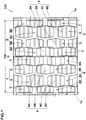
- the pneumatic tire 1 is provided in the tread portion 2 with axially innermost first blocks 3 and axially outer blocks 4.
- the axially outer blocks 4 are disposed between the axially innermost first blocks 3 and each of the tread edges Te.
- the axially innermost first blocks 3 are disposed on each side of the tire equator C.
- the axially innermost first blocks 3 are arranged in two circumferential rows.
- the axially outer blocks 4 are arranged in three circumferential rows on each side of the tire equator C.
- the three circumferential rows are a row of second blocks 5 adjacent to the axially innermost first blocks 3, a row of fourth blocks 7 adjacent to the tread edge Te, and a row of third blocks 6 between the row of the second blocks 5 and the row of the fourth blocks 7.
- the lateral grooves 8 are first lateral grooves 8A between the axially innermost first blocks 3, second lateral grooves 8B between the second blocks 5, third lateral grooves 8C between the third blocks 6, and fourth lateral grooves 8D between the fourth blocks 7.
- each of the blocks 3 and 4 is provided with sipes 9 extending across the entire axial width of the block to have both ends opened.
- the sipes 9 are first sipes 9A disposed in each of the axially innermost first blocks 3, second sipes 9B disposed in each of the second blocks 5, third sipes 9C disposed in each of the third blocks 6, and fourth sipes 9D disposed in each of the axially outermost fourth blocks 7.
- sipes having closed ends are not counted.
- wear energy that a tire rolling on a road surface is subjected to is largely related to (almost proportional to) a product of the amount of slippage between the tire and the road surface and the ground pressure of the tire.
- the ground pressure has more influence on the wear energy than the amount of slippage.
- the amount of slippage (lateral force) has more influence on the wear energy than the ground pressure.
- the longitudinal block rigidity defined by the equation (1) which can be easily calculated is employed as the above-mentioned rigidities of each block in both directions.
- the longitudinal block rigidity (G) of the axially innermost first blocks 3 within a range of from 90 % to 110 % of the longitudinal block rigidity (G) of the axially outer blocks 4, it is possible to reduce the difference between the rigidities of the blocks 3, 4.
- the blocks 3 and 4 are worn evenly under usual combination running of straight running and cornering. Therefore, the tire 1 according to the present invention can be improved in the wear resistance performance, while maintaining on-icy-road performance at high level.
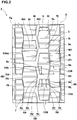
- the tread of each of the axially innermost first blocks 3 has a pentagonal shape.
- the width w1 in the tire axial direction of the axially innermost first block 3 is gradually decreased from its central portion 3s toward its each end 3t in the tire circumferential direction.
- the ends 3t can be appropriately deformed when the axially innermost first block 3 steps on the ground and kicks back against the ground.
- the slippage of the axially innermost first block 3 on the road surface is reduced.
- the wear energy that the axially innermost first block 3 is subjected to is decreased, and the wear resistance performance can be improved.
- the axially innermost first block 3 has an inside block edge 3A extending in the tire circumferential direction on its tire equator C side, and an outside block edge 3B extending in the tire circumferential direction on its outside in the tire axial direction.
- the axially outside block edge 3B comprises a first oblique part 3a inclined with respect to the tire circumferential direction to one tire axial direction, and a second oblique part 3b inclined with respect to the tire circumferential direction to the other tire axial direction.
- the inside block edge 3A is straight and parallel with the tire circumferential direction. Such inside block edge 3A does not reduce the rigidity in the tire circumferential direction of an adjacent portion of the axially innermost first block 3 which portion is subjected to the highest ground pressure, therefore, wear occurring in the adjacent portion to the edge 3A during straight running can be reduced.
- the tread of each of the second blocks 5 has a hexagonal shape.
- the width w2 in the tire axial direction of the second block 5 is gradually decreased from its central portion 5s toward its each end 5t in the tire circumferential direction.
- the ends 5t suppress the slippage of the block 5 on the road surface, and the wear resistance performance is improved.
- the second block 5 has an inside block edge 5A extending in the tire circumferential direction on its tire equator C side, and an outside block edge 5B extending in the tire circumferential direction on its outside in the tire axial direction.
- the axially inside block edge 5A comprises a first oblique part 5a inclined with respect to the tire circumferential direction to one tire axial direction, and a second oblique part 5b inclined with respect to the tire circumferential direction to the other tire axial direction.
- the axially outside block edge 5B comprises a third oblique part 5c inclined with respect to the tire circumferential direction to one tire axial direction, and a fourth oblique part 5d inclined with respect to the tire circumferential direction to the other tire axial direction.
- the second block 5 Since the second block 5 does not have block edges parallel with the tire circumferential direction, such second block 5 becomes smaller in the rigidity in the tire axial direction in comparison with the axially innermost first block 3. However, since the central portion 5s bulges toward both sides in the tire axial direction, the second block 5 has an axial edge component larger than that of the axially innermost first block 3. Therefore, the second block 5, which is subjected to lower ground pressure and larger lateral force than the axially innermost first blocks 3, has preferable rigidity, and the wear of the second block becomes close to the wear of the axially innermost first block 3.
- the first oblique part 5a of the inside block edge 5A of each of the second blocks 5 overlaps in the tire circumferential direction with the first oblique part 3a of the axially outside block edge 3B of one of the axially innermost first blocks 3 to form an overlap 12A.
- the second oblique part 5b of the inside block edge 5A of each of the second blocks 5 overlaps in the tire circumferential direction with the second oblique part 3b of the axially outside block edge 3B of one of the axially innermost first blocks 3 to form an overlap 12B.
- the blocks 3, 5 can support each other in the overlaps 12A and 12B, therefore, the deformation of the blocks 3, 5 is suppressed to reduce the slippage on the road surface, and the wear resistance performance can be improved.
- the maximum width B2 in the tire axial direction of the second block 5 is more than the maximum width in the tire axial direction B1 of the axially innermost first block 3.
- the second block 5 is subjected to a larger lateral force than that of the axially innermost first block 3, therefore, by setting the rigidity in the tire axial direction of the second block 5 as being higher than the rigidity in the tire axial direction of the axially innermost first block 3, it is possible to reduce the difference in wear between the axially innermost first block 3 and the second block 5. If the maximum width B2 in the tire axial direction of the second block 5 is excessively large, there is a possibility that the difference in the rigidity between the axially innermost first block 3 and the second block 5 becomes large, and the wear resistance performance is deteriorated.
- the maximum width B1 of the axially innermost first block 3 is set in a range of from 90 % to 98 % of the maximum width B2 of the second block 5.
- the maximum width B1 of the axially innermost first block 3 is set in a range of from 5 % to 15 % of the tread width TW.
- the tread of each of the third blocks 6 has a hexagonal shape.
- the width w3 in the tire axial direction of the third block 6 is gradually decreased from its central portion 6s toward its each end 6t in the tire circumferential direction.
- the ends 6t suppress the slippage of the block 6 on the road surface, and the wear resistance performance is improved.
- the third block 6 has an inside block edge 6A extending in the tire circumferential direction on its tire equator C side, and an outside block edge 6B extending in the tire circumferential direction on its outside in the tire axial direction.
- the axially inside block edge 6A comprises a first oblique part 6a inclined with respect to the tire circumferential direction to one tire axial direction, and a second oblique part 6b inclined with respect to the tire circumferential direction to the other tire axial direction.
- the axially outside block edge 6B comprises a third oblique part 6c inclined with respect to the tire circumferential direction to one tire axial direction, and a fourth oblique part 6d inclined with respect to the tire circumferential direction to the other tire axial direction.
- the first oblique part 6a of the inside block edge 6A of each of the third blocks 6 overlaps in the tire circumferential direction with the third oblique part 5c of the axially outside block edge 5B of one of the second blocks 5 to form an overlap 13A.
- the second oblique part 6b of the inside block edge 6A of each of the third blocks 6 overlaps in the tire circumferential direction with the fourth oblique part 5d of the axially outside block edge 5B one of the second blocks 5 to form an overlap 13B.
- the maximum width in the tire axial direction B3 of the third block 6 is more than the maximum width B2 of the second block 5.
- the third block 6 is subjected to a larger lateral force than that of the second block 5, therefore, by setting the rigidity in the tire axial direction of the third block 6 as being higher than the rigidity in the tire axial direction of the second block 5, it is possible to reduce the difference in wear between the second block 5 and the third block 6. If the maximum width in the tire axial direction B3 of the third block 6 is excessively large, there is a possibility that the wear resistance performance is deteriorated for the same reason as above. Therefore, the maximum width B2 of the second block 5 is more preferably set in a range of from 75 % to 85 % of the maximum width B3 of the third block 6.
- the tread of each of the fourth blocks 7 has a pentagonal shape.
- the width w4 in the tire axial direction of the fourth block 7 is decreased from its central portion 7s toward its each end 7t in the tire circumferential direction, In such fourth block 7, the ends 7t suppress the slippage of the block 7 on the road surface similarly to the axially innermost first block 3, and the wear resistance performance is improved.
- the axially outermost fourth block 7 has an inside block edge 7A extending in the tire circumferential direction on its tire equator C side, and an outside block edge 7B extending in the tire circumferential direction on its outside in the tire axial direction.
- the axially inside block edge 7A comprises a first oblique part 7a inclined with respect to the tire circumferential direction to one tire axial direction, and a second oblique part 7b inclined with respect to the tire circumferential direction to the other tire axial direction.
- the axially outside block edge 7B extends straight in parallel with the tire circumferential direction. Such axially outside block edge 7B does not reduce the rigidity in the tire circumferential direction of an adjacent portion of the fourth block 7 which portion is subjected to the largest lateral force, therefore, the wear resistance performance is improved.
- the first oblique part 7a of the inside block edge 7A of each of the fourth blocks 7 overlaps in the tire circumferential direction with the third oblique part 6c of the axially outside block edge 6B of one of the third blocks 6 to form an overlap 14A.
- the second oblique part 7b of the inside block edge 7A of each of the fourth blocks 7 overlaps in the tire circumferential direction with the fourth oblique part 6d of the axially outside block edge 6B of one of the third blocks 6 to form an overlap 14B.
- the third blocks 6 and/or fourth blocks 7 are subjected to large force in the tire circumferential direction or axial direction which can largely deform the blocks 6, 7, the blocks 6, 7 can support each other in the overlaps 14A and 14B, therefore, the deformation of the blocks 6, 7 is suppressed, and the wear resistance performance can be improved.
- the axially outside block edge 3B of each of the axially innermost first blocks 3, both of the block edges 5A and 5B of each of the second blocks 5, both of the block edges 6A and 6B of each of the third blocks 6, and the axially inside block edge 7A of each of the fourth blocks 7 each have an inclination angle ⁇ 1 with respect to the tire circumferential direction which is preferably not less than 5 degrees, more preferably not less than 7 degrees, but preferably not more than 15 degrees, more preferably not more than 13 degrees.
- the maximum width B4 in the tire axial direction of the fourth block 7 (shown in Fig. 4 ) is set in a range of from 5 % to 15 % of the tread width TW in order to maintain the rigidity.
- the lateral grooves 8A, 8B, 8C and 8D each extend straight in order not to partially reduce the rigidities of adjacent portions of the blocks 3 and 4 to the lateral grooves 8 and not to deteriorate the wear resistance performance.
- the lateral grooves 8 are parallel with the tire axial direction in order that edges 10 of the blocks 3 and 4 abutting on the lateral grooves 8 can exert their maximum edge effects to improve the on-icy-road performance.
- the lateral grooves 8 may have various configurations such as zigzag configurations and inclined straight configurations.
- the groove width w5 of the first lateral groove 8A is set to be less than the groove width w6 of the second lateral groove 8B in order that the maximum length A1 in the tire circumferential direction of the axially innermost first block 3 becomes more than the maximum length A2 in the tire circumferential direction of the second block 5. Therefore, it is possible to increase the rigidity in the tire circumferential direction of the axially innermost first block 3 which is subjected to a higher ground pressure than that of the second block 5 during straight running, and thereby it is possible to decrease the difference in the wear between the axially innermost first blocks 3 and the second blocks 5.
- the groove width w5 of the first lateral groove 8A is preferably set in a range of from 90 % to 98 % of the groove width w6 of the second lateral groove 8B.
- the groove width w5 of the first lateral groove 8A is preferably set in a range of from 2 % to 9 % of the tread width TW in order that ice shaved off by the blocks' edges 10 and sipes' edges is effectively removed from the treads of the blocks into the first lateral grooves 8A.
- the groove width w6 of the second lateral groove 8B is set to be less than the groove width w7 of the third lateral groove 8C in order that the maximum length A2 in the tire circumferential direction of the second block 5 becomes more than the maximum length in the tire circumferential direction A3 of the third block 6. Therefore, it is possible to increase the rigidity in the tire circumferential direction of the second block 5 which is subjected to a larger ground pressure than that of the third block 6, and thereby, it is possible to decrease the difference in the wear between the second blocks 5 and the third blocks 6.
- the groove width w6 of the second lateral groove 8B is preferably set in a range of from 80 % to 90 % of the groove width w7 of the third lateral groove 8C.
- the groove width w8 of the fourth lateral groove 8D is set in a range of from 90 % to 110 % of the groove width w7 of the third lateral groove 8C in order to secure a large maximum length A4 in the tire axial direction of the fourth block 7 to increase the rigidity in the tire circumferential direction of the fourth block 7.
- the groove depth (not shown) of the lateral groove 8 is set in a range of from 8 to 16 mm.
- All of the sipes 9A, 9B, 9C and 9D extend straight in order not to partially decrease the rigidity of each block 3, 4 and not to deteriorate the wear resistance performance.
- the sipes 9A, 9B, 9C and 9D may be provided with zigzag configurations for example.
- All of the sipes 9A, 9B, 9C and 9D are parallel with the tire axial direction in order that the sipes 9A, 9B, 9C and 9D can exert their maximum edge effects in the tire rotational direction to improve the on-icy-road performance.
- sipes 9A, 9B, 9C and 9D may be inclined with respect to the tire axial direction.
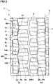
- the sipes 9 disposed in all of the blocks 3 and 4 are the same in the sipe number (six) and the same in the sipe arrangement or circumferential pitches P (large-small-large-small-large-small-large). Therefore, the sipes 9 in each block 3, 4 are described hereunder based on the first sipes 9A disposed in the first block 3 with reference to Fig. 5 .
- the pitches P between the sipes 9A are not constant in the tire circumferential direction, and thereby the first block 3 is divided into small block pieces 31 having a smaller width L1 in the tire circumferential direction, and large block pieces 32 having a larger width L2 in the tire circumferential direction than the small block pieces 31.
- the small block pieces 31 can be deformed relatively easily during running on icy roads, the edges of the small block pieces 31 effectively scratch the icy road surface, and on-icy-road performance is improved. Since the large block pieces 32 are relatively hard to be deformed, the large block pieces 32 contact with the icy road surface to secure a necessary ground contacting area.
- the small block pieces 31 and the large block pieces 32 are arranged alternately in the tire circumferential direction in order that the large block pieces 32 prevent the small block pieces 31 from being deformed excessively, and the wear of the block 3 becomes uniform.
- the on-icy-road performance and the wear resistance performance can be improved in good balance.
- the first block 3 includes three or more small block pieces 31 in order to exert the edge effect effectively.
- the small block pieces 31 are a small block piece 36 having the maximum width B1 in the tire axial direction (shown in Fig. 4 ) of the first block 3, and a pair of second small block pieces 37 disposed one on each side in the tire circumferential direction of the first small block piece 36, and each of the small block pieces 31 is sandwiched between the large block pieces 32 to prevent an excessive deformation.
- the ratio L2/L1 of the width L2 in the tire circumferential direction of the large block piece 32 to the width L1 in the tire circumferential direction of the small block piece 31 is preferably not less than 3.0, more preferably not less than 3.5, but preferably not more than 5.0, more preferably not more than 4.5. Thereby, the on-icy-road performance and the wear resistance can be improved in good balance.
- the width L1 in the tire circumferential direction of the small block piece 31 is preferably 2 % to 10 % of the maximum length A in the tire circumferential direction (shown in Fig. 4 ) of the first block 3.
- first sipes 9A disposed in the first block 3 can be applied to the second sipes 9B disposed in the second block 5 by replacing the first sipe 9A and the first block 3 with the second sipe 9B and the second block 5 respectively, the third sipes 9C disposed in the third block 6 by replacing the first sipe 9A and the first block 3 with the third sipe 9C and the third block 6 respectively, and the fourth sipes 9D disposed in the fourth block 7 by replacing the first sipe 9A and the first block 3 with the fourth sipe 9D and the fourth block 7 respectively.
- the depth of the third sipes 9C (not shown) of the third blocks 6 is more than the depth of the first sipes 9A of the first blocks 3, and more than the depth of the second sipes 9B of the second blocks 5.
- the third blocks 6 are subjected to smaller pressure than those of the first blocks 3 and the second blocks 5, therefore, by making the depth of the third sipes 9C larger, it is possible to reduce wear difference among the first blocks 3 through the third blocks 6, and thereby their edge effects can be maintained for a long time.
- the depth of the first sipes and the depth of the second sipes 9B are preferably set in a range of from 70 % to 90 % of the groove depth of the second lateral grooves 8B.
- the depth of the third sipes 9C is preferably set in a range of from 87 % to 97 % of the groove depth of the second lateral grooves 8B.
- the depth of the third sipes 9C is more than the depth of the fourth sipes 9D of the fourth blocks 7.
- the third blocks 6 are subjected to lateral force smaller than that of the fourth blocks 7, therefore, by making the depth of the third sipes 9C larger, it is possible to reduce wear difference between the third blocks 6 and the fourth blocks 7, and thereby their edge effects can be maintained for a long time.
- the summation CE of edge lengths of the sipes 9A and 9B disposed in all of the first blocks 3 and the second blocks 5, is preferably not less than 30000 mm, more preferably not less than 33000 mm, but preferably not more than 40000 mm, more preferably not more than 37000 mm.
- the edge length of a sipe is the total length of the two edges of the sipe.
- the summation SE of edge lengths of the sipes 9C and 9D disposed in all of the third blocks 6 and fourth blocks 7, is preferably not less than 30000 mm, more preferably not less than 33000 mm, but preferably not more than 40000 mm, more preferably not more than 37000 mm.
- test vehicles (2-D-wheel-type 10 ton truck) provided on all wheels with the same kind of test tires inflated to 900 kPa.
Landscapes
- Engineering & Computer Science (AREA)
- Mechanical Engineering (AREA)
- Tires In General (AREA)
Claims (9)
- Luftreifen (1), umfassend einen Laufflächenabschnitt (2), der mit einer Vielzahl von Blöcken versehen ist, die jeweils mit Feinschnitten (9) versehen sind, die sich über die gesamte axiale Breite des Blocks (3, 4) erstrecken,
wobei die Blöcke axial innerste erste Blöcke (3) mit jeweils einer Längsblocksteifigkeit (G) und axial äußere Blöcke (4) mit jeweils einer Längsblocksteifigkeit (G) umfassen, und die Längsblocksteifigkeit (G) der axial innersten ersten Blöcke (3) 90 % bis 110 % der Längsblocksteifigkeit (G) der axial äußeren Blöcke (4) beträgt, wobei
die Längsblocksteifigkeit (G) eines Blocks durch die folgende Gleichung definiert ist: G = (A × B)/(C × D × E),
wobeiA die maximale Länge in der Reifenumfangsrichtung des Blocks ist,B die maximale Breite in der axialen Richtung des Reifens des Blocks ist,C die maximale Rillentiefe von Querrillen ist, die auf beiden Seiten des Blocks in der Reifenumfangsrichtung so angeordnet sind, dass sie den Block in Umfangsrichtung teilen,D die maximale Tiefe der in dem Block angeordneten Feinschnitte ist undE die Anzahl der in dem Block angeordneten Feinschnitte ist,dadurch gekennzeichnet, dass
die axial äußeren Blöcke (4) zweite Blöcke (5) umfassen, die benachbart zu den axial innersten ersten Blöcken (3) liegen, und
die maximale Breite (B1) in der axialen Reifenrichtung der axial innersten ersten Blöcke (3) kleiner ist als die maximale Breite (B2) in der axialen Reifenrichtung der zweiten Blöcke (5). - Luftreifen nach Anspruch 1, wobei
die Querrillen (8) erste Querrillen (8A) zwischen den axial innersten ersten Blöcken (3) und zweite Querrillen (8B) zwischen den zweiten Blöcken (5) umfassen, und
die Rillenbreite (W5) der ersten Querrillen (8A) kleiner ist als die Rillenbreite (W6) der zweiten Querrillen (8B). - Luftreifen nach Anspruch 1 oder 2, wobei
die axial äußeren Blöcke (4) dritte Blöcke (6) umfassen, die axial außerhalb der zweiten Blöcke (5) benachbart dazu angeordnet sind, und
die maximale Breite (B2) in der axialen Reifenrichtung der zweiten Blöcke (5) kleiner ist als die maximale Breite (B3) in der axialen Reifenrichtung der dritten Blöcke (6). - Luftreifen nach Anspruch 3, wobei
die Querrillen (8) dritte Querrillen (8C) zwischen den dritten Blöcken (6) umfassen, und
die Rillenbreite (W6) der zweiten Querrillen (8B) kleiner ist als die Rillenbreite (W7) der dritten Querrillen (8C). - Luftreifen nach Anspruch 3 oder 4, wobei die Tiefe der Feinschnitte (9C) der dritten Blöcke (6) größer ist als die Tiefe der Feinschnitte (9A) der axial innersten ersten Blöcke (3) und größer ist als die Tiefe der Feinschnitte (9B) der zweiten Blöcke (5).
- Luftreifen nach Anspruch 4 oder 5, wobei
die axial äußeren Blöcke (4) vierte Blöcke (7) umfassen, die zwischen den dritten Blöcken (6) und der Laufflächenkante (Te) angeordnet sind,
die Summe der Kantenlängen der in allen axial innersten ersten Blöcken (3) und zweiten Blöcken (5) angeordneten Feinschnitte (9A, 9B) 30000 bis 40000 mm beträgt, und
die Summe der Kantenlängen der in allen dritten Blöcken (6) und vierten Blöcken (7) angeordneten Feinschnitte (9C, 9D) 30000 bis 40000 mm beträgt. - Luftreifen nach einem der Ansprüche 1-6, wobei
jeder der Blöcke (3, 4) in der Reifenumfangsrichtung durch eine Vielzahl von Feinschnitten (9) in kleine Blockstücke (31) und große Blockstücke (32) unterteilt ist, die abwechselnd in Reifenumfangsrichtung angeordnet sind,
die kleinen Blockstücke (31) eine kleinere Breite L1 in der Reifenumfangsrichtung aufweisen, und
die großen Blockstücke (32) eine größere Breite L2 in der Reifenumfangsrichtung aufweisen als die Breite (L1) der kleinen Blockstücke (31). - Luftreifen nach Anspruch 7, wobei das Verhältnis L2/L1 der Breite L2 in der Reifenumfangsrichtung der großen Blockstücke zur Breite L1 in der Reifenumfangsrichtung der kleinen Blockstücke 3,0 bis 5,0 beträgt.
- Luftreifen nach Anspruch 7 oder 8, wobei jeder der Blöcke 3 oder mehr kleine Blockstücke (31) umfasst.
Applications Claiming Priority (1)
| Application Number | Priority Date | Filing Date | Title |
|---|---|---|---|
| JP2014252350A JP6154798B2 (ja) | 2014-12-12 | 2014-12-12 | 空気入りタイヤ |
Publications (2)
| Publication Number | Publication Date |
|---|---|
| EP3031624A1 EP3031624A1 (de) | 2016-06-15 |
| EP3031624B1 true EP3031624B1 (de) | 2019-06-05 |
Family
ID=54780224
Family Applications (1)
| Application Number | Title | Priority Date | Filing Date |
|---|---|---|---|
| EP15197860.8A Active EP3031624B1 (de) | 2014-12-12 | 2015-12-03 | Luftreifen |
Country Status (4)
| Country | Link |
|---|---|
| US (1) | US10232670B2 (de) |
| EP (1) | EP3031624B1 (de) |
| JP (1) | JP6154798B2 (de) |
| CN (1) | CN105691113B (de) |
Families Citing this family (4)
| Publication number | Priority date | Publication date | Assignee | Title |
|---|---|---|---|---|
| JP1535306S (de) * | 2015-04-24 | 2018-10-01 | ||
| USD801259S1 (en) * | 2015-07-10 | 2017-10-31 | Compagnie Generale Des Etablissements Michelin | Tire tread |
| CN109094302B (zh) * | 2017-06-20 | 2022-01-28 | 住友橡胶工业株式会社 | 充气轮胎 |
| US11731463B2 (en) * | 2019-08-28 | 2023-08-22 | Sumitomo Rubber Industries, Ltd. | Tire |
Family Cites Families (19)
| Publication number | Priority date | Publication date | Assignee | Title |
|---|---|---|---|---|
| US2186180A (en) * | 1936-04-29 | 1940-01-09 | Us Rubber Co | Pneumatic tire |
| JP2814095B2 (ja) * | 1989-02-10 | 1998-10-22 | 横浜ゴム株式会社 | 空気入りタイヤ |
| JP2693637B2 (ja) * | 1990-11-15 | 1997-12-24 | 株式会社ブリヂストン | 氷結湿濡地表上での走行性能に優れる空気入りタイヤ |
| JPH04215505A (ja) * | 1990-12-14 | 1992-08-06 | Bridgestone Corp | 氷結湿濡地表上での走行性能に優れる空気入りタイヤ |
| EP0540339B1 (de) * | 1991-11-01 | 1998-05-20 | Bridgestone Corporation | Luftreifen |
| US5385189A (en) * | 1991-11-01 | 1995-01-31 | Bridgestone Corporation | Pneumatic tire with paired sides in the tread |
| JP3064271B2 (ja) | 1998-11-20 | 2000-07-12 | 住友ゴム工業株式会社 | 自動車およびそれに用いる前輪用と後輪用の空気入りタイヤの組み合わせ |
| JP2001030715A (ja) * | 1999-07-16 | 2001-02-06 | Ohtsu Tire & Rubber Co Ltd :The | 空気入りタイヤ |
| JP2005067232A (ja) * | 2003-08-25 | 2005-03-17 | Yokohama Rubber Co Ltd:The | 空気入りタイヤ |
| JP4299745B2 (ja) * | 2004-08-12 | 2009-07-22 | 住友ゴム工業株式会社 | 空気入りタイヤ |
| JP4312141B2 (ja) * | 2004-10-13 | 2009-08-12 | 住友ゴム工業株式会社 | 重荷重用ラジアルタイヤ |
| JP4913508B2 (ja) * | 2006-08-30 | 2012-04-11 | 株式会社ブリヂストン | 空気入りタイヤ |
| JP5038739B2 (ja) * | 2007-02-22 | 2012-10-03 | 住友ゴム工業株式会社 | スタッドレスタイヤ |
| JP4388569B2 (ja) * | 2007-08-01 | 2009-12-24 | 住友ゴム工業株式会社 | 空気入りタイヤ |
| JP2009190558A (ja) | 2008-02-14 | 2009-08-27 | Bridgestone Corp | 空気入りタイヤ |
| JP5200123B2 (ja) * | 2011-01-28 | 2013-05-15 | 住友ゴム工業株式会社 | 重荷重用空気入りタイヤ |
| JP5790166B2 (ja) * | 2011-06-02 | 2015-10-07 | 横浜ゴム株式会社 | 空気入りタイヤ |
| JP5480867B2 (ja) * | 2011-10-07 | 2014-04-23 | 住友ゴム工業株式会社 | 空気入りタイヤ |
| EP2808179B1 (de) | 2013-05-27 | 2015-10-21 | Sumitomo Rubber Industries, Ltd. | Luftreifen |
-
2014
- 2014-12-12 JP JP2014252350A patent/JP6154798B2/ja active Active
-
2015
- 2015-11-26 CN CN201510836485.2A patent/CN105691113B/zh active Active
- 2015-11-30 US US14/954,102 patent/US10232670B2/en active Active
- 2015-12-03 EP EP15197860.8A patent/EP3031624B1/de active Active
Non-Patent Citations (1)
| Title |
|---|
| None * |
Also Published As
| Publication number | Publication date |
|---|---|
| US10232670B2 (en) | 2019-03-19 |
| US20160167442A1 (en) | 2016-06-16 |
| JP2016112993A (ja) | 2016-06-23 |
| JP6154798B2 (ja) | 2017-06-28 |
| CN105691113B (zh) | 2019-08-13 |
| CN105691113A (zh) | 2016-06-22 |
| EP3031624A1 (de) | 2016-06-15 |
Similar Documents
| Publication | Publication Date | Title |
|---|---|---|
| EP3025879B1 (de) | Luftreifen | |
| US10046607B2 (en) | Winter tire | |
| EP3000621B1 (de) | Luftreifen | |
| EP2821256B1 (de) | Luftreifen | |
| EP2952362B1 (de) | Luftreifen | |
| EP2907674B1 (de) | Luftreifen | |
| US10836215B2 (en) | Tire | |
| EP2578418B1 (de) | Luftreifen | |
| EP2239153B1 (de) | Luftreifen | |
| EP3012119B1 (de) | Luftreifen | |
| EP2287016B1 (de) | Luftreifen | |
| EP3135504B1 (de) | Schwerlastreifen | |
| EP3098090B1 (de) | Winterreifen | |
| EP2808179A1 (de) | Luftreifen | |
| EP3444131B1 (de) | Reifen | |
| EP3042792A1 (de) | Luftreifen | |
| EP3263365A1 (de) | Reifen | |
| EP2452836B1 (de) | Schwerlast-Luftreifen | |
| EP3575110B1 (de) | Reifen | |
| EP3031624B1 (de) | Luftreifen | |
| EP3025878B1 (de) | Schwerlastluftreifen | |
| EP3321103B1 (de) | Schwerlastreifen | |
| EP3925796B1 (de) | Reifen | |
| EP3825150B1 (de) | Reifen |
Legal Events
| Date | Code | Title | Description |
|---|---|---|---|
| PUAI | Public reference made under article 153(3) epc to a published international application that has entered the european phase |
Free format text: ORIGINAL CODE: 0009012 |
|
| AK | Designated contracting states |
Kind code of ref document: A1 Designated state(s): AL AT BE BG CH CY CZ DE DK EE ES FI FR GB GR HR HU IE IS IT LI LT LU LV MC MK MT NL NO PL PT RO RS SE SI SK SM TR |
|
| AX | Request for extension of the european patent |
Extension state: BA ME |
|
| STAA | Information on the status of an ep patent application or granted ep patent |
Free format text: STATUS: REQUEST FOR EXAMINATION WAS MADE |
|
| 17P | Request for examination filed |
Effective date: 20161031 |
|
| RBV | Designated contracting states (corrected) |
Designated state(s): AL AT BE BG CH CY CZ DE DK EE ES FI FR GB GR HR HU IE IS IT LI LT LU LV MC MK MT NL NO PL PT RO RS SE SI SK SM TR |
|
| GRAP | Despatch of communication of intention to grant a patent |
Free format text: ORIGINAL CODE: EPIDOSNIGR1 |
|
| STAA | Information on the status of an ep patent application or granted ep patent |
Free format text: STATUS: GRANT OF PATENT IS INTENDED |
|
| RIC1 | Information provided on ipc code assigned before grant |
Ipc: B60C 11/12 20060101ALI20190213BHEP Ipc: B60C 11/03 20060101AFI20190213BHEP Ipc: B60C 11/11 20060101ALI20190213BHEP |
|
| INTG | Intention to grant announced |
Effective date: 20190312 |
|
| GRAS | Grant fee paid |
Free format text: ORIGINAL CODE: EPIDOSNIGR3 |
|
| GRAA | (expected) grant |
Free format text: ORIGINAL CODE: 0009210 |
|
| STAA | Information on the status of an ep patent application or granted ep patent |
Free format text: STATUS: THE PATENT HAS BEEN GRANTED |
|
| AK | Designated contracting states |
Kind code of ref document: B1 Designated state(s): AL AT BE BG CH CY CZ DE DK EE ES FI FR GB GR HR HU IE IS IT LI LT LU LV MC MK MT NL NO PL PT RO RS SE SI SK SM TR |
|
| REG | Reference to a national code |
Ref country code: GB Ref legal event code: FG4D |
|
| REG | Reference to a national code |
Ref country code: CH Ref legal event code: EP |
|
| REG | Reference to a national code |
Ref country code: AT Ref legal event code: REF Ref document number: 1139607 Country of ref document: AT Kind code of ref document: T Effective date: 20190615 |
|
| REG | Reference to a national code |
Ref country code: IE Ref legal event code: FG4D |
|
| REG | Reference to a national code |
Ref country code: DE Ref legal event code: R096 Ref document number: 602015031317 Country of ref document: DE |
|
| REG | Reference to a national code |
Ref country code: NL Ref legal event code: MP Effective date: 20190605 |
|
| REG | Reference to a national code |
Ref country code: LT Ref legal event code: MG4D |
|
| PG25 | Lapsed in a contracting state [announced via postgrant information from national office to epo] |
Ref country code: LT Free format text: LAPSE BECAUSE OF FAILURE TO SUBMIT A TRANSLATION OF THE DESCRIPTION OR TO PAY THE FEE WITHIN THE PRESCRIBED TIME-LIMIT Effective date: 20190605 Ref country code: HR Free format text: LAPSE BECAUSE OF FAILURE TO SUBMIT A TRANSLATION OF THE DESCRIPTION OR TO PAY THE FEE WITHIN THE PRESCRIBED TIME-LIMIT Effective date: 20190605 Ref country code: NO Free format text: LAPSE BECAUSE OF FAILURE TO SUBMIT A TRANSLATION OF THE DESCRIPTION OR TO PAY THE FEE WITHIN THE PRESCRIBED TIME-LIMIT Effective date: 20190905 Ref country code: SE Free format text: LAPSE BECAUSE OF FAILURE TO SUBMIT A TRANSLATION OF THE DESCRIPTION OR TO PAY THE FEE WITHIN THE PRESCRIBED TIME-LIMIT Effective date: 20190605 Ref country code: FI Free format text: LAPSE BECAUSE OF FAILURE TO SUBMIT A TRANSLATION OF THE DESCRIPTION OR TO PAY THE FEE WITHIN THE PRESCRIBED TIME-LIMIT Effective date: 20190605 Ref country code: AL Free format text: LAPSE BECAUSE OF FAILURE TO SUBMIT A TRANSLATION OF THE DESCRIPTION OR TO PAY THE FEE WITHIN THE PRESCRIBED TIME-LIMIT Effective date: 20190605 Ref country code: ES Free format text: LAPSE BECAUSE OF FAILURE TO SUBMIT A TRANSLATION OF THE DESCRIPTION OR TO PAY THE FEE WITHIN THE PRESCRIBED TIME-LIMIT Effective date: 20190605 |
|
| PG25 | Lapsed in a contracting state [announced via postgrant information from national office to epo] |
Ref country code: BG Free format text: LAPSE BECAUSE OF FAILURE TO SUBMIT A TRANSLATION OF THE DESCRIPTION OR TO PAY THE FEE WITHIN THE PRESCRIBED TIME-LIMIT Effective date: 20190905 Ref country code: LV Free format text: LAPSE BECAUSE OF FAILURE TO SUBMIT A TRANSLATION OF THE DESCRIPTION OR TO PAY THE FEE WITHIN THE PRESCRIBED TIME-LIMIT Effective date: 20190605 Ref country code: RS Free format text: LAPSE BECAUSE OF FAILURE TO SUBMIT A TRANSLATION OF THE DESCRIPTION OR TO PAY THE FEE WITHIN THE PRESCRIBED TIME-LIMIT Effective date: 20190605 Ref country code: GR Free format text: LAPSE BECAUSE OF FAILURE TO SUBMIT A TRANSLATION OF THE DESCRIPTION OR TO PAY THE FEE WITHIN THE PRESCRIBED TIME-LIMIT Effective date: 20190906 |
|
| REG | Reference to a national code |
Ref country code: AT Ref legal event code: MK05 Ref document number: 1139607 Country of ref document: AT Kind code of ref document: T Effective date: 20190605 |
|
| PG25 | Lapsed in a contracting state [announced via postgrant information from national office to epo] |
Ref country code: NL Free format text: LAPSE BECAUSE OF FAILURE TO SUBMIT A TRANSLATION OF THE DESCRIPTION OR TO PAY THE FEE WITHIN THE PRESCRIBED TIME-LIMIT Effective date: 20190605 Ref country code: CZ Free format text: LAPSE BECAUSE OF FAILURE TO SUBMIT A TRANSLATION OF THE DESCRIPTION OR TO PAY THE FEE WITHIN THE PRESCRIBED TIME-LIMIT Effective date: 20190605 Ref country code: AT Free format text: LAPSE BECAUSE OF FAILURE TO SUBMIT A TRANSLATION OF THE DESCRIPTION OR TO PAY THE FEE WITHIN THE PRESCRIBED TIME-LIMIT Effective date: 20190605 Ref country code: RO Free format text: LAPSE BECAUSE OF FAILURE TO SUBMIT A TRANSLATION OF THE DESCRIPTION OR TO PAY THE FEE WITHIN THE PRESCRIBED TIME-LIMIT Effective date: 20190605 Ref country code: EE Free format text: LAPSE BECAUSE OF FAILURE TO SUBMIT A TRANSLATION OF THE DESCRIPTION OR TO PAY THE FEE WITHIN THE PRESCRIBED TIME-LIMIT Effective date: 20190605 Ref country code: PT Free format text: LAPSE BECAUSE OF FAILURE TO SUBMIT A TRANSLATION OF THE DESCRIPTION OR TO PAY THE FEE WITHIN THE PRESCRIBED TIME-LIMIT Effective date: 20191007 Ref country code: SK Free format text: LAPSE BECAUSE OF FAILURE TO SUBMIT A TRANSLATION OF THE DESCRIPTION OR TO PAY THE FEE WITHIN THE PRESCRIBED TIME-LIMIT Effective date: 20190605 |
|
| PG25 | Lapsed in a contracting state [announced via postgrant information from national office to epo] |
Ref country code: SM Free format text: LAPSE BECAUSE OF FAILURE TO SUBMIT A TRANSLATION OF THE DESCRIPTION OR TO PAY THE FEE WITHIN THE PRESCRIBED TIME-LIMIT Effective date: 20190605 Ref country code: IT Free format text: LAPSE BECAUSE OF FAILURE TO SUBMIT A TRANSLATION OF THE DESCRIPTION OR TO PAY THE FEE WITHIN THE PRESCRIBED TIME-LIMIT Effective date: 20190605 Ref country code: IS Free format text: LAPSE BECAUSE OF FAILURE TO SUBMIT A TRANSLATION OF THE DESCRIPTION OR TO PAY THE FEE WITHIN THE PRESCRIBED TIME-LIMIT Effective date: 20191005 |
|
| REG | Reference to a national code |
Ref country code: DE Ref legal event code: R097 Ref document number: 602015031317 Country of ref document: DE |
|
| PG25 | Lapsed in a contracting state [announced via postgrant information from national office to epo] |
Ref country code: TR Free format text: LAPSE BECAUSE OF FAILURE TO SUBMIT A TRANSLATION OF THE DESCRIPTION OR TO PAY THE FEE WITHIN THE PRESCRIBED TIME-LIMIT Effective date: 20190605 |
|
| PLBE | No opposition filed within time limit |
Free format text: ORIGINAL CODE: 0009261 |
|
| STAA | Information on the status of an ep patent application or granted ep patent |
Free format text: STATUS: NO OPPOSITION FILED WITHIN TIME LIMIT |
|
| PG25 | Lapsed in a contracting state [announced via postgrant information from national office to epo] |
Ref country code: PL Free format text: LAPSE BECAUSE OF FAILURE TO SUBMIT A TRANSLATION OF THE DESCRIPTION OR TO PAY THE FEE WITHIN THE PRESCRIBED TIME-LIMIT Effective date: 20190605 Ref country code: DK Free format text: LAPSE BECAUSE OF FAILURE TO SUBMIT A TRANSLATION OF THE DESCRIPTION OR TO PAY THE FEE WITHIN THE PRESCRIBED TIME-LIMIT Effective date: 20190605 |
|
| 26N | No opposition filed |
Effective date: 20200306 |
|
| PG25 | Lapsed in a contracting state [announced via postgrant information from national office to epo] |
Ref country code: SI Free format text: LAPSE BECAUSE OF FAILURE TO SUBMIT A TRANSLATION OF THE DESCRIPTION OR TO PAY THE FEE WITHIN THE PRESCRIBED TIME-LIMIT Effective date: 20190605 |
|
| REG | Reference to a national code |
Ref country code: CH Ref legal event code: PL |
|
| REG | Reference to a national code |
Ref country code: BE Ref legal event code: MM Effective date: 20191231 |
|
| PG25 | Lapsed in a contracting state [announced via postgrant information from national office to epo] |
Ref country code: MC Free format text: LAPSE BECAUSE OF FAILURE TO SUBMIT A TRANSLATION OF THE DESCRIPTION OR TO PAY THE FEE WITHIN THE PRESCRIBED TIME-LIMIT Effective date: 20190605 |
|
| GBPC | Gb: european patent ceased through non-payment of renewal fee |
Effective date: 20191203 |
|
| PG25 | Lapsed in a contracting state [announced via postgrant information from national office to epo] |
Ref country code: LU Free format text: LAPSE BECAUSE OF NON-PAYMENT OF DUE FEES Effective date: 20191203 Ref country code: GB Free format text: LAPSE BECAUSE OF NON-PAYMENT OF DUE FEES Effective date: 20191203 Ref country code: IE Free format text: LAPSE BECAUSE OF NON-PAYMENT OF DUE FEES Effective date: 20191203 |
|
| PG25 | Lapsed in a contracting state [announced via postgrant information from national office to epo] |
Ref country code: BE Free format text: LAPSE BECAUSE OF NON-PAYMENT OF DUE FEES Effective date: 20191231 Ref country code: LI Free format text: LAPSE BECAUSE OF NON-PAYMENT OF DUE FEES Effective date: 20191231 Ref country code: CH Free format text: LAPSE BECAUSE OF NON-PAYMENT OF DUE FEES Effective date: 20191231 |
|
| PG25 | Lapsed in a contracting state [announced via postgrant information from national office to epo] |
Ref country code: CY Free format text: LAPSE BECAUSE OF FAILURE TO SUBMIT A TRANSLATION OF THE DESCRIPTION OR TO PAY THE FEE WITHIN THE PRESCRIBED TIME-LIMIT Effective date: 20190605 |
|
| PG25 | Lapsed in a contracting state [announced via postgrant information from national office to epo] |
Ref country code: MT Free format text: LAPSE BECAUSE OF FAILURE TO SUBMIT A TRANSLATION OF THE DESCRIPTION OR TO PAY THE FEE WITHIN THE PRESCRIBED TIME-LIMIT Effective date: 20190605 Ref country code: HU Free format text: LAPSE BECAUSE OF FAILURE TO SUBMIT A TRANSLATION OF THE DESCRIPTION OR TO PAY THE FEE WITHIN THE PRESCRIBED TIME-LIMIT; INVALID AB INITIO Effective date: 20151203 |
|
| PG25 | Lapsed in a contracting state [announced via postgrant information from national office to epo] |
Ref country code: MK Free format text: LAPSE BECAUSE OF FAILURE TO SUBMIT A TRANSLATION OF THE DESCRIPTION OR TO PAY THE FEE WITHIN THE PRESCRIBED TIME-LIMIT Effective date: 20190605 |
|
| P01 | Opt-out of the competence of the unified patent court (upc) registered |
Effective date: 20230510 |
|
| PGFP | Annual fee paid to national office [announced via postgrant information from national office to epo] |
Ref country code: FR Payment date: 20231108 Year of fee payment: 9 Ref country code: DE Payment date: 20231031 Year of fee payment: 9 |