EP3321103B1 - Schwerlastreifen - Google Patents
Schwerlastreifen Download PDFInfo
- Publication number
- EP3321103B1 EP3321103B1 EP17198178.0A EP17198178A EP3321103B1 EP 3321103 B1 EP3321103 B1 EP 3321103B1 EP 17198178 A EP17198178 A EP 17198178A EP 3321103 B1 EP3321103 B1 EP 3321103B1
- Authority
- EP
- European Patent Office
- Prior art keywords
- shoulder
- groove
- tire
- circumferential
- width
- Prior art date
- Legal status (The legal status is an assumption and is not a legal conclusion. Google has not performed a legal analysis and makes no representation as to the accuracy of the status listed.)
- Active
Links
- 239000011324 bead Substances 0.000 description 3
- XLYOFNOQVPJJNP-UHFFFAOYSA-N water Substances O XLYOFNOQVPJJNP-UHFFFAOYSA-N 0.000 description 3
- 230000000052 comparative effect Effects 0.000 description 2
- 230000003247 decreasing effect Effects 0.000 description 2
- 238000007373 indentation Methods 0.000 description 2
- 239000010426 asphalt Substances 0.000 description 1
- 230000005540 biological transmission Effects 0.000 description 1
- 230000008520 organization Effects 0.000 description 1
- 230000003014 reinforcing effect Effects 0.000 description 1
- 230000002195 synergetic effect Effects 0.000 description 1
Images

Classifications
-
- B—PERFORMING OPERATIONS; TRANSPORTING
- B60—VEHICLES IN GENERAL
- B60C—VEHICLE TYRES; TYRE INFLATION; TYRE CHANGING; CONNECTING VALVES TO INFLATABLE ELASTIC BODIES IN GENERAL; DEVICES OR ARRANGEMENTS RELATED TO TYRES
- B60C11/00—Tyre tread bands; Tread patterns; Anti-skid inserts
- B60C11/03—Tread patterns
- B60C11/0306—Patterns comprising block rows or discontinuous ribs
-
- B—PERFORMING OPERATIONS; TRANSPORTING
- B60—VEHICLES IN GENERAL
- B60C—VEHICLE TYRES; TYRE INFLATION; TYRE CHANGING; CONNECTING VALVES TO INFLATABLE ELASTIC BODIES IN GENERAL; DEVICES OR ARRANGEMENTS RELATED TO TYRES
- B60C11/00—Tyre tread bands; Tread patterns; Anti-skid inserts
- B60C11/03—Tread patterns
-
- B—PERFORMING OPERATIONS; TRANSPORTING
- B60—VEHICLES IN GENERAL
- B60C—VEHICLE TYRES; TYRE INFLATION; TYRE CHANGING; CONNECTING VALVES TO INFLATABLE ELASTIC BODIES IN GENERAL; DEVICES OR ARRANGEMENTS RELATED TO TYRES
- B60C11/00—Tyre tread bands; Tread patterns; Anti-skid inserts
- B60C11/01—Shape of the shoulders between tread and sidewall, e.g. rounded, stepped or cantilevered
-
- B—PERFORMING OPERATIONS; TRANSPORTING
- B60—VEHICLES IN GENERAL
- B60C—VEHICLE TYRES; TYRE INFLATION; TYRE CHANGING; CONNECTING VALVES TO INFLATABLE ELASTIC BODIES IN GENERAL; DEVICES OR ARRANGEMENTS RELATED TO TYRES
- B60C11/00—Tyre tread bands; Tread patterns; Anti-skid inserts
- B60C11/03—Tread patterns
- B60C11/12—Tread patterns characterised by the use of narrow slits or incisions, e.g. sipes
- B60C11/1236—Tread patterns characterised by the use of narrow slits or incisions, e.g. sipes with special arrangements in the tread pattern
-
- B—PERFORMING OPERATIONS; TRANSPORTING
- B60—VEHICLES IN GENERAL
- B60C—VEHICLE TYRES; TYRE INFLATION; TYRE CHANGING; CONNECTING VALVES TO INFLATABLE ELASTIC BODIES IN GENERAL; DEVICES OR ARRANGEMENTS RELATED TO TYRES
- B60C11/00—Tyre tread bands; Tread patterns; Anti-skid inserts
- B60C11/03—Tread patterns
- B60C11/04—Tread patterns in which the raised area of the pattern consists only of continuous circumferential ribs, e.g. zig-zag
-
- B—PERFORMING OPERATIONS; TRANSPORTING
- B60—VEHICLES IN GENERAL
- B60C—VEHICLE TYRES; TYRE INFLATION; TYRE CHANGING; CONNECTING VALVES TO INFLATABLE ELASTIC BODIES IN GENERAL; DEVICES OR ARRANGEMENTS RELATED TO TYRES
- B60C11/00—Tyre tread bands; Tread patterns; Anti-skid inserts
- B60C11/03—Tread patterns
- B60C2011/0337—Tread patterns characterised by particular design features of the pattern
- B60C2011/0339—Grooves
- B60C2011/0341—Circumferential grooves
- B60C2011/0344—Circumferential grooves provided at the equatorial plane
-
- B—PERFORMING OPERATIONS; TRANSPORTING
- B60—VEHICLES IN GENERAL
- B60C—VEHICLE TYRES; TYRE INFLATION; TYRE CHANGING; CONNECTING VALVES TO INFLATABLE ELASTIC BODIES IN GENERAL; DEVICES OR ARRANGEMENTS RELATED TO TYRES
- B60C11/00—Tyre tread bands; Tread patterns; Anti-skid inserts
- B60C11/03—Tread patterns
- B60C2011/0337—Tread patterns characterised by particular design features of the pattern
- B60C2011/0339—Grooves
- B60C2011/0341—Circumferential grooves
- B60C2011/0346—Circumferential grooves with zigzag shape
-
- B—PERFORMING OPERATIONS; TRANSPORTING
- B60—VEHICLES IN GENERAL
- B60C—VEHICLE TYRES; TYRE INFLATION; TYRE CHANGING; CONNECTING VALVES TO INFLATABLE ELASTIC BODIES IN GENERAL; DEVICES OR ARRANGEMENTS RELATED TO TYRES
- B60C11/00—Tyre tread bands; Tread patterns; Anti-skid inserts
- B60C11/03—Tread patterns
- B60C2011/0337—Tread patterns characterised by particular design features of the pattern
- B60C2011/0339—Grooves
- B60C2011/0341—Circumferential grooves
- B60C2011/0353—Circumferential grooves characterised by width
-
- B—PERFORMING OPERATIONS; TRANSPORTING
- B60—VEHICLES IN GENERAL
- B60C—VEHICLE TYRES; TYRE INFLATION; TYRE CHANGING; CONNECTING VALVES TO INFLATABLE ELASTIC BODIES IN GENERAL; DEVICES OR ARRANGEMENTS RELATED TO TYRES
- B60C11/00—Tyre tread bands; Tread patterns; Anti-skid inserts
- B60C11/03—Tread patterns
- B60C2011/0337—Tread patterns characterised by particular design features of the pattern
- B60C2011/0339—Grooves
- B60C2011/0358—Lateral grooves, i.e. having an angle of 45 to 90 degees to the equatorial plane
- B60C2011/0362—Shallow grooves, i.e. having a depth of less than 50% of other grooves
-
- B—PERFORMING OPERATIONS; TRANSPORTING
- B60—VEHICLES IN GENERAL
- B60C—VEHICLE TYRES; TYRE INFLATION; TYRE CHANGING; CONNECTING VALVES TO INFLATABLE ELASTIC BODIES IN GENERAL; DEVICES OR ARRANGEMENTS RELATED TO TYRES
- B60C11/00—Tyre tread bands; Tread patterns; Anti-skid inserts
- B60C11/03—Tread patterns
- B60C11/12—Tread patterns characterised by the use of narrow slits or incisions, e.g. sipes
- B60C11/1204—Tread patterns characterised by the use of narrow slits or incisions, e.g. sipes with special shape of the sipe
- B60C2011/1213—Tread patterns characterised by the use of narrow slits or incisions, e.g. sipes with special shape of the sipe sinusoidal or zigzag at the tread surface
-
- B—PERFORMING OPERATIONS; TRANSPORTING
- B60—VEHICLES IN GENERAL
- B60C—VEHICLE TYRES; TYRE INFLATION; TYRE CHANGING; CONNECTING VALVES TO INFLATABLE ELASTIC BODIES IN GENERAL; DEVICES OR ARRANGEMENTS RELATED TO TYRES
- B60C2200/00—Tyres specially adapted for particular applications
- B60C2200/06—Tyres specially adapted for particular applications for heavy duty vehicles
Definitions
- the present invention relates to a heavy duty tire, more particularly to a tread pattern capable of improving tread center wear without sacrificing wet performance of the tire.
- tread center wear where the crown region wears more than the other regions is liable to occur when the tire is mounted on a drive axle of a heavy duty vehicle such as truck and bus.
- the drive power of the heavy duty vehicle is especially large, and the contour of the tread portion of the tire is convexly curved such that the diameter of the tire becomes larger in the crown region than in the shoulder regions, and the crown region is subjected to the drive power more than the shoulder regions.
- the rigidity of the tread portion is increased in the crown region by increasing the ground contacting area of the ground contacting elements such as blocks and/or ribs formed in the crown region.
- the ground contacting area is increased in the crown region, widths of grooves formed in the crown region are decreased and wet performance is deteriorated.
- Japanese Patent Application Publication No. H08-282213 discloses a heavy duly tire, wherein, in order to increase the uneven wear resistance, the axial distance from the tire equator to the widthwise center line of each shoulder circumferential groove is set in a rage from 0.25 to 0.40 times the tread width, and the crown region is divided into blocks by narrow axial grooves and narrow circumferential grooves. Even in such tire, however, results which can completely satisfy both the tread center wear and the wet performance are not yet obtained.
- EP 2 474 428 A1 discloses a heavy duty tire comprising the features according to the preamble of claim 1.
- a heavy duty tire comprises:
- each of the shoulder blocks is provided with an auxiliary shoulder axial groove extending parallel with the adjacent shoulder axial grooves, and the groove depth of the auxiliary shoulder axial groove is less than the groove depth of the adjacent shoulder axial grooves.
- each of the crown land regions is provided with crown sipes extending across the entire axial width of the crown land region
- each of the middle land regions is provided with middle sipes extending across the entire axial width of the middle land region.
- each of the center circumferential groove, the middle circumferential grooves and the shoulder circumferential grooves is a zigzag groove having a portion which has a certain constant width and extends linearly in the tire circumferential direction within the width of the zigzag groove.
- each of the shoulder blocks is curved convexly to the axially outside in the form of an arc.
- the tread edges TE are the axial outermost edges of the ground contacting patch of the tire which occurs under a normally inflated loaded condition when the camber angle of the tire is zero.
- the tread width is the width measured under the normally inflated unloaded condition, as the axial distance between the tread edges TE determined as above.
- the normally inflated unloaded condition is such that the tire is mounted on a standard wheel rim and inflate to a standard pressure but loaded with no tire load.
- the normally inflated loaded condition is such that the tire is mounted on the standard wheel rim and inflated to the standard pressure and loaded with the standard tire load.
- the standard wheel rim is a wheel rim officially approved or recommended for the tire by standards organizations, i.e. JATMA (Japan and Asia), T&RA (North America), ETRTO (Europe), TRAA (Australia), STRO (Scandinavia), ALAPA (Latin America), ITTAC (India) and the like which are effective in the area where the tire is manufactured, sold or used.
- the standard pressure and the standard tire load are the maximum air pressure and the maximum tire load for the tire specified by the same organization in the Air-pressure/Maximum-load Table or similar list.
- the standard wheel rim is the "standard rim” specified in JATMA, the "Measuring Rim” in ETRTO, the "Design Rim” in TRA or the like.
- the standard pressure is the “maximum air pressure” in JATMA, the “inflation Pressure” in ETRTO, the maximum pressure given in the “Tire Load Limits at Various Cold Inflation Pressures” table in TRA or the like.
- the standard load is the "maximum load capacity" in JATMA, the “Load Capacity” in ETRTO, the maximum value given in the above-mentioned table in TRA or the like.
- groove width means a width of a groove measured perpendicularly to the longitudinal direction of the groove at the groove top at the tread.
- tape means a very narrow groove whose groove width is less than 1.5 mm inclusive of a cut having no substantial width.
- the tread pattern rigidity in the crown region is increased to suppress the tread center wear while securing the drainage (wet performance).
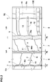
- a heavy duty tire 1 as an embodiment of the present invention is a pneumatic tire comprising a tread portion 2 whose outer surface defines the tread, a pair of axially spaced bead portions mounted on rim seats, a pair of sidewall portions extending between the tread edges and the bead portions, a carcass extending between the bead portions through the tread portion and the sidewall portions, and a tread reinforcing belt disposed radially outside the carcass in the tread portion as well known in the art.
- the tread portion 2 is provided with circumferentially continuously extending circumferential grooves which are a center circumferential groove 3 disposed on the tire equator Co, a middle circumferential groove 4 disposed on each side in the tire axial direction of the center circumferential groove 3, a shoulder circumferential groove 5 disposed axially outside each of the middle circumferential grooves 4.
- the tread portion 2 is therefore, axially divided into two crown land regions 6 between the middle circumferential grooves 4 and the center circumferential groove 3, two middle land regions 7 between the middle circumferential grooves 4 and the shoulder circumferential grooves 5, and two shoulder land regions 8 axially outside the respective shoulder circumferential grooves 5.
- a region between the shoulder circumferential grooves 5 is called “crown region Yc”
- a region axially outside each of the shoulder circumferential grooves 5 is called “shoulder region Ys”.
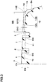
- the center circumferential groove 3, the middle circumferential grooves 4 and the shoulder circumferential grooves 5 are each formed as a zigzag groove J in order to increase the axial component of the groove edges to improve the traction.
- the zigzag groove J means:
- the center circumferential groove 3 and the shoulder circumferential grooves 5 are the first type zigzag groove J1.
- the middle circumferential grooves 4 are the second type zigzag groove J2.
- each of the zigzag grooves J or the circumferential grooves 3, 4 and 5 has a portion Hj, which is defined as having a certain constant width and extending linearly in the tire circumferential direction, within the width of the zigzag groove in order to provide good drainage performance.
- the axial distance LA from the center line of each shoulder circumferential groove 5 to the tire equator Co is more than the axial distance LB from the center line of the same shoulder circumferential groove 5 to the tread edge TE.
- the center line is the center line of the zigzag amplitude of the groove.
- the center line is the widthwise center line of the straight groove.
- the groove width Wc of the center circumferential groove 3 is set to be more than 3.0 mm and less than 6.0 mm.
- the groove width Wm of each of the middle circumferential grooves 4 is set to be more than 3.0 mm and less than 6.0 mm.
- the groove width Ws of each of the shoulder circumferential grooves 5 is set to be more than 5.0 mm, and more than the groove width Wc and the groove width Wm.
- the crown region Yc becomes wider than the shoulder region Ys and the prerequisite for increasing the tread pattern rigidity in the crown region Yc is upheld. Further, by setting the groove widths Wc and Wm of the circumferential grooves 3 and 4 disposed in the crown region Yc in a range between more than 3.0 mm and less than 6.0 mm, it becomes possible to form the crown land regions 6 and the middle land regions 7 as being wide while securing the drainage. Furthermore, the crown land regions 6 and the middle land regions 7 are formed as circumferentially continuously extending ribs. By the combination of those actions, it is possible to increase the tread pattern rigidity in the crown region Yc to suppress the tread center wear while securing the drainage.
- the ratio LA/LB is preferably not less than 1.10, more preferably not less than 1.20. If LA/LB is too large, the tread pattern rigidity in the shoulder regions Ys is decreased, and the steering stability is deteriorated. Based on this standpoint, the LA/LB is preferably not more than 1.40, more preferably not more than 1.30.
- the groove widths Wc and Wm are less than 3.0 mm, the drainage becomes insufficient. If the groove widths Wc and Wm are more than 6.0 mm, the improving of the tread center wear becomes insufficient although the drainage is improved. If the groove width Ws is less than 5.0 mm and less than the groove widths Wc and Wm, the drainage becomes insufficient although the tread center wear is improved.
- the groove depths DG of the center circumferential groove 3, the middle circumferential grooves 4 and the shoulder circumferential grooves 5 are preferably set in a range from 15 to 18 mm.
- each of the crown land regions 6 is provided with crown sipes 10 extending across the entire width of the crown land region 6.
- each of the middle land regions 7 is provided with middle sipes 11 extending across the entire width of the middle land region 7.
- the crown sipes 10 and middle sipes 11 are closed when in the ground contact patch, and the tread pattern rigidity is maintained. Further, the crown sipes 10 and middle sipes 11 improve the wet performance since the sipes' edges can break through a water film covering the road surface, and at the same time, the sipes can absorb the water on the road surface.
- the crown sipes 10 and the middle sipes 11 are each inclined with respect to the tire axial direction at an angle ⁇ of not more than 30 degrees for example.
- the crown sipes 10 are inclined with respect to the tire axial direction to one circumferential direction, whereas the middle sipes 11 are inclined with respect to the tire axial direction to the other circumferential direction opposite to the crown sipes 10.
- the crown sipes 10 on both sides of the tire equator are inclined in the same direction.
- the ends positioned on both sides of each of the circumferential grooves 3 and 4 and connected thereto are staggered in order to uniform the rigidity of the crown region Yc. Further, the ends of the center and middle sipes 10 and 11 are respectively connected to the bent points of the first type zigzag groove J1 and the indentations K of the second type zigzag groove J2 as shown in Fig. 1 .
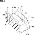
- Each of the shoulder land regions 8 is provided with shoulder axial grooves 12 extending across the entire width of the shoulder land region 8 so that the shoulder land region 8 is circumferentially divided into shoulder blocks 13 in a row.
- each of the shoulder axial grooves 12 is composed of a main portion 12A having a constant groove depth D12 and extending over at least 70 % of the axial width w8 of the shoulder land region 8 from the shoulder circumferential groove 5, and an axially outer end portion 12B extending from the main portion 12A while increasing the depth to open at the buttress surface Bs or the outer surface of the radially outermost part of the tire sidewall.
- the groove depth D12 of the main portion 12A is less than the groove depth DG of the shoulder circumferential groove 5, preferably not more than 50 %, more preferably not more than 30 % of the groove depth DG.
- such shallow shoulder axial grooves 12 can maintain the rigidity of the shoulder blocks 13, and the tread pattern rigidity is balanced between the crown region Yc and the shoulder regions Ys.
- the axially outer edge 13E of each of the shoulder blocks 13 is curved convexly toward the axially outside in the form of an arc in order to improve the wandering performance of the tire.
- the tread edge TE is positioned at the axially outermost point P of the outer edge 13E as defined as above.
- each shoulder block 13 extending radially inwardly from the outer edge 13E to the above-mentioned buttress surface Bs is formed as a part of a conic surface inclined to the axially outside.
- the shoulder blocks 13 are each provided with an auxiliary axial groove 16 extending parallel with the shoulder axial grooves 12 on both sides of the shoulder block, and having a width narrower than the shoulder axial grooves 12.
- the auxiliary axial groove 16 extends across the entire width of the shoulder block 13 and has a constant groove depth D16 along the entire length thereof.
- the groove depth D16 is not more than the above-mentioned groove depth D12 of the main portion 12A of the shoulder axial groove 12.
- the auxiliary axial grooves 16 improve the drainage and traction performance while maintaining the rigidity of the shoulder blocks 13.
- each of the shoulder axial grooves 12 and the auxiliary axial groove 16 is a bent groove as shown in Figs. 1 and 2 , although those in Fig. 4 are illustrated as straight grooves for the sake of simplicity. Nevertheless, it may be possible to form the shoulder axial grooves 12 and the auxiliary axial groove 16 as straight grooves as shown in Fig. 4 .
- pneumatic tires of size 315/80R22.5 (rim size 22.5X9.00) for heavy duty vehicles were experimentally manufactured as test tires (Embodiment tires Ex.1 - Ex.4 and Comparative tires Ref.1 - Ref.7) and tested for the resistance to tread center wear and wet performance.
- test tires had the same specifications. Common specifications are as follows:
- the test was conducted using a 10-ton truck provided on all wheels with test tires inflated to 830 kPa and loaded with 50% of the load capacity on a front part of the rear deck. After running for 40000 km, the drive axle tires were measured to obtain (1) an average value of the amounts of wear at the positions of the center circumferential groove and middle circumferential grooves, and (2) an average value of the amounts of wear at the positions of the axially outer side walls of the respective shoulder circumferential grooves. Then, the difference between the average values (1) and (2) was calculated. The difference is indicated in Table 1 by an index based on Embodiment tire Ex.1 being 100, wherein the larger the value, the higher the resistance to tread center wear. If the index value is under 90, the resistance to tread center wear is considered as not good.
- the test was conducted similarly using a 10-ton truck provided on all wheels with test tires (tire pressure 830 kPa) and loaded with 50% of the load capacity on a front part of the rear deck, but the tread portions of the test tires were worn 75 %.
- the truck On an asphalt road surface covered with 5 mm depth water, the truck was started under such a condition that the transmission was fixed to the second gear and the rotating speed of the engine was fixed to 1500 rpm, and the time required to run for 10 meters was measured immediately after the clutch was engaged.
- the reciprocal of the time is indicated in Table 1 by an index based on Embodiment tire Ex.1 being 100, wherein the larger the value, the better the wet performance. If the index value is under 90, the wet performance is considered as not good.
Landscapes
- Engineering & Computer Science (AREA)
- Mechanical Engineering (AREA)
- Tires In General (AREA)
Claims (5)
- Schwerlastreifen (1), umfassend:einen Laufflächenabschnitt (2), der mit einer zentralen umlaufenden Rille (3), die an dem Reifenäquator (Co) angeordnet ist, mit einer axial äußeren umlaufenden Schulterrille (5), die auf jeder Seite des Reifenäquators (Co) angeordnet ist, mit einer mittleren umlaufenden Rille (4), die zwischen der zentralen umlaufenden Rille (3) und jeder der umlaufenden Schulterrillen (5) derart angeordnet ist, dass der Laufflächenabschnitt (2) zwischen den mittleren umlaufenden Rillen (4) und der zentralen umlaufenden Rille (3) axial in zwei Kronenlandbereiche (6) geteilt ist, mit zwei mittleren Landbereichen (7) zwischen den mittleren umlaufenden Rillen (4) und den umlaufenden Schulterrillen (5) sowie mit zwei Schulterlandbereichen (8) axial außerhalb der umlaufenden Schulterrillen (5) versehen ist,
wobeijeder der Kronenlandbereiche (6) und der mittleren Landbereiche (7) eine sich in Umfangsrichtung kontinuierlich erstreckende Rippe ist,jeder der Schulterlandbereiche (8) mit axialen Schulterrillen (12) versehen ist, die sich über die gesamte axiale Breite des Schulterlandbereichs (8) erstrecken, und in Schulterblöcke (13) geteilt ist,auf jeder Seite des Reifenäquators (Co) eine axiale Distanz (LA) von der Mittelachse der umlaufenden Schulterrille (5) bis zu dem Reifenäquator (Co) größer als eine axiale Distanz (LB) von der Mittelachse der umlaufenden Schulterrille (5) bis zu dem Laufflächenrand (TE) ist, wobei die Laufflächenränder (TE) die axial äußersten Ränder der Bodenaufstandsfläche des Reifens sind, welche vorhanden ist, wenn der Reifen an seiner Standardradfelge montiert ist, bis zu seinem maximalen Luftdruck aufgepumpt ist und bis zu seiner maximalen Last beladen ist und wenn der Sturzwinkel des Reifens Null ist, undeine Rillenbreite (Ws) jeder der umlaufenden Schulterrillen (5) größer als 5.0 mm ist und größer als eine Rillenbreite (Wc) der zentralen umlaufenden Rille (3) und eine Rillenbreite (Wm) der mittleren umlaufenden Rillen (4) ist,
dadurch gekennzeichnet, dassdie Rillenbreite (Wc) der zentralen umlaufenden Rille (3) größer als 3,0 mm und kleiner als 6,0 mm ist unddie Rillenbreite (Wm) jeder der mittleren umlaufenden Rillen (4) größer als 3,0 mm und kleiner als 6,0 mm ist. - Schwerlastreifen (1) nach Anspruch 1, wobei
jeder der Schulterblöcke (13) mit einer axialen Hilfsrille (16) versehen ist, die sich parallel zu den axialen Schulterrillen (12) erstreckt. - Schwerlastreifen (1) nach Anspruch 1 oder 2, wobeijeder der Kronenlandbereiche (6) mit Kronenfeinschnitten (10) versehen ist, die sich über die gesamte axiale Breite des Kronenlandbereichs (6) erstrecken, undjeder der mittleren Landbereiche (7) mit mittleren Feinschnitten (11) versehen ist, die sich über die gesamte axiale Breite des mittleren Landbereichs (7) erstrecken,wobei die Kronenfeinschnitte (10) und die mittleren Feinschnitte (11) geschlossen sind, wenn sie sich in der Bodenaufstandsfläche befinden.
- Schwerlastreifen nach Anspruch 1, 2 oder 3, wobei
jede von der zentralen umlaufenden Rille (3), den mittleren umlaufenden Rillen (4) und den umlaufenden Schulterrillen (5) eine Zickzackrille (J) ist, die einen Abschnitt aufweist, der eine bestimmte konstante Breite aufweist und sich innerhalb der Breite der Zickzackrille (J) linear in der Umfangsrichtung des Reifens erstreckt. - Schwerlastreifen (1) nach Anspruch 1, 2, 3 oder 4, wobei
ein axial äußerer Rand (13E) jedes der Schulterblöcke (13) in Richtung der axialen Außenseite in der Form eines Bogens konvex gekrümmt ist.
Applications Claiming Priority (1)
| Application Number | Priority Date | Filing Date | Title |
|---|---|---|---|
| JP2016220893A JP6801386B2 (ja) | 2016-11-11 | 2016-11-11 | 重荷重用タイヤ |
Publications (2)
| Publication Number | Publication Date |
|---|---|
| EP3321103A1 EP3321103A1 (de) | 2018-05-16 |
| EP3321103B1 true EP3321103B1 (de) | 2019-07-03 |
Family
ID=60182431
Family Applications (1)
| Application Number | Title | Priority Date | Filing Date |
|---|---|---|---|
| EP17198178.0A Active EP3321103B1 (de) | 2016-11-11 | 2017-10-25 | Schwerlastreifen |
Country Status (4)
| Country | Link |
|---|---|
| US (1) | US10744822B2 (de) |
| EP (1) | EP3321103B1 (de) |
| JP (1) | JP6801386B2 (de) |
| CN (1) | CN108068555A (de) |
Families Citing this family (3)
| Publication number | Priority date | Publication date | Assignee | Title |
|---|---|---|---|---|
| JP6867121B2 (ja) * | 2016-08-03 | 2021-04-28 | Toyo Tire株式会社 | 空気入りタイヤ |
| JP7126987B2 (ja) * | 2019-06-14 | 2022-08-29 | 株式会社ブリヂストン | タイヤ |
| JP7516753B2 (ja) * | 2019-12-16 | 2024-07-17 | 住友ゴム工業株式会社 | タイヤ |
Family Cites Families (21)
| Publication number | Priority date | Publication date | Assignee | Title |
|---|---|---|---|---|
| GB2170153B (en) * | 1984-12-14 | 1989-07-19 | Bridgestone Corp | Pneumatic radial tire |
| JPH06191229A (ja) * | 1992-12-24 | 1994-07-12 | Yokohama Rubber Co Ltd:The | 空気入りラジアルタイヤ |
| JP2966760B2 (ja) * | 1995-04-18 | 1999-10-25 | 住友ゴム工業株式会社 | 重荷重用タイヤ |
| JPH1148719A (ja) * | 1997-08-07 | 1999-02-23 | Bridgestone Corp | 重荷重用空気入りタイヤ |
| JP3045495B1 (ja) * | 1998-12-18 | 2000-05-29 | 住友ゴム工業株式会社 | 空気入りタイヤ |
| JP3490943B2 (ja) * | 1999-12-17 | 2004-01-26 | 住友ゴム工業株式会社 | 空気入りタイヤ |
| KR20030062778A (ko) * | 2002-01-19 | 2003-07-28 | 금호산업주식회사 | 편마모 발생 억제구조를 갖는 공기입 레디알 타이어의트레드 패턴 |
| JP2005329795A (ja) * | 2004-05-19 | 2005-12-02 | Yokohama Rubber Co Ltd:The | 空気入りタイヤ |
| JP4528091B2 (ja) * | 2004-10-29 | 2010-08-18 | 株式会社ブリヂストン | 空気入りタイヤ |
| JP5210334B2 (ja) * | 2010-02-05 | 2013-06-12 | 住友ゴム工業株式会社 | 重荷重用タイヤ |
| JP5693069B2 (ja) * | 2010-07-16 | 2015-04-01 | 株式会社ブリヂストン | 重荷重用空気入りタイヤ |
| JP5216832B2 (ja) * | 2010-10-25 | 2013-06-19 | 株式会社ブリヂストン | 加硫済トレッド |
| JP5771398B2 (ja) * | 2011-01-11 | 2015-08-26 | 株式会社ブリヂストン | 空気入りタイヤ |
| JP5860609B2 (ja) * | 2011-04-07 | 2016-02-16 | 株式会社ブリヂストン | 空気入りタイヤ |
| DE102011051387A1 (de) * | 2011-06-28 | 2013-01-03 | Continental Reifen Deutschland Gmbh | Fahrzeugluftreifen |
| WO2013051053A1 (ja) * | 2011-10-03 | 2013-04-11 | 株式会社ブリヂストン | 重荷重用空気入りタイヤ |
| JP5498466B2 (ja) * | 2011-10-20 | 2014-05-21 | 住友ゴム工業株式会社 | 重荷重用タイヤ |
| JP5432967B2 (ja) * | 2011-10-27 | 2014-03-05 | 住友ゴム工業株式会社 | 空気入りタイヤ |
| JP5476410B2 (ja) * | 2012-03-15 | 2014-04-23 | 住友ゴム工業株式会社 | 空気入りタイヤ |
| DE102012104799A1 (de) * | 2012-06-01 | 2013-12-05 | Continental Reifen Deutschland Gmbh | Fahrzeugluftreifen |
| JP6356961B2 (ja) * | 2013-12-16 | 2018-07-11 | 住友ゴム工業株式会社 | 重荷重用タイヤ |
-
2016
- 2016-11-11 JP JP2016220893A patent/JP6801386B2/ja active Active
-
2017
- 2017-09-29 CN CN201710907994.9A patent/CN108068555A/zh active Pending
- 2017-10-20 US US15/788,936 patent/US10744822B2/en active Active
- 2017-10-25 EP EP17198178.0A patent/EP3321103B1/de active Active
Non-Patent Citations (1)
| Title |
|---|
| None * |
Also Published As
| Publication number | Publication date |
|---|---|
| US10744822B2 (en) | 2020-08-18 |
| JP6801386B2 (ja) | 2020-12-16 |
| CN108068555A (zh) | 2018-05-25 |
| US20180134090A1 (en) | 2018-05-17 |
| JP2018076039A (ja) | 2018-05-17 |
| EP3321103A1 (de) | 2018-05-16 |
Similar Documents
| Publication | Publication Date | Title |
|---|---|---|
| EP3000621B1 (de) | Luftreifen | |
| EP3093162B1 (de) | Luftreifen | |
| EP3025879B1 (de) | Luftreifen | |
| EP2952362B1 (de) | Luftreifen | |
| EP3205516B1 (de) | Luftreifen | |
| US10836215B2 (en) | Tire | |
| EP2239153B1 (de) | Luftreifen | |
| EP2982520B1 (de) | Luftreifen | |
| US10369847B2 (en) | Heavy duty tire | |
| US10967683B2 (en) | Pneumatic tire | |
| US11325426B2 (en) | Tire | |
| US11285762B2 (en) | Tyre | |
| US20180272809A1 (en) | Pneumatic tire | |
| US20230137297A1 (en) | Tire | |
| US11654721B2 (en) | Tire | |
| EP3025878B1 (de) | Schwerlastluftreifen | |
| EP3321103B1 (de) | Schwerlastreifen | |
| US10232670B2 (en) | Pneumatic tire | |
| US11524529B2 (en) | Tire | |
| US20210061018A1 (en) | Tire | |
| EP3925796B1 (de) | Reifen |
Legal Events
| Date | Code | Title | Description |
|---|---|---|---|
| PUAI | Public reference made under article 153(3) epc to a published international application that has entered the european phase |
Free format text: ORIGINAL CODE: 0009012 |
|
| STAA | Information on the status of an ep patent application or granted ep patent |
Free format text: STATUS: THE APPLICATION HAS BEEN PUBLISHED |
|
| AK | Designated contracting states |
Kind code of ref document: A1 Designated state(s): AL AT BE BG CH CY CZ DE DK EE ES FI FR GB GR HR HU IE IS IT LI LT LU LV MC MK MT NL NO PL PT RO RS SE SI SK SM TR |
|
| AX | Request for extension of the european patent |
Extension state: BA ME |
|
| STAA | Information on the status of an ep patent application or granted ep patent |
Free format text: STATUS: REQUEST FOR EXAMINATION WAS MADE |
|
| 17P | Request for examination filed |
Effective date: 20181009 |
|
| RBV | Designated contracting states (corrected) |
Designated state(s): AL AT BE BG CH CY CZ DE DK EE ES FI FR GB GR HR HU IE IS IT LI LT LU LV MC MK MT NL NO PL PT RO RS SE SI SK SM TR |
|
| GRAP | Despatch of communication of intention to grant a patent |
Free format text: ORIGINAL CODE: EPIDOSNIGR1 |
|
| STAA | Information on the status of an ep patent application or granted ep patent |
Free format text: STATUS: GRANT OF PATENT IS INTENDED |
|
| RIC1 | Information provided on ipc code assigned before grant |
Ipc: B60C 11/04 20060101ALI20190227BHEP Ipc: B60C 11/03 20060101AFI20190227BHEP Ipc: B60C 11/12 20060101ALI20190227BHEP Ipc: B60C 11/01 20060101ALI20190227BHEP |
|
| INTG | Intention to grant announced |
Effective date: 20190401 |
|
| GRAS | Grant fee paid |
Free format text: ORIGINAL CODE: EPIDOSNIGR3 |
|
| GRAA | (expected) grant |
Free format text: ORIGINAL CODE: 0009210 |
|
| STAA | Information on the status of an ep patent application or granted ep patent |
Free format text: STATUS: THE PATENT HAS BEEN GRANTED |
|
| AK | Designated contracting states |
Kind code of ref document: B1 Designated state(s): AL AT BE BG CH CY CZ DE DK EE ES FI FR GB GR HR HU IE IS IT LI LT LU LV MC MK MT NL NO PL PT RO RS SE SI SK SM TR |
|
| REG | Reference to a national code |
Ref country code: GB Ref legal event code: FG4D |
|
| REG | Reference to a national code |
Ref country code: CH Ref legal event code: EP Ref country code: AT Ref legal event code: REF Ref document number: 1150539 Country of ref document: AT Kind code of ref document: T Effective date: 20190715 |
|
| REG | Reference to a national code |
Ref country code: IE Ref legal event code: FG4D |
|
| REG | Reference to a national code |
Ref country code: DE Ref legal event code: R096 Ref document number: 602017005015 Country of ref document: DE |
|
| REG | Reference to a national code |
Ref country code: NL Ref legal event code: MP Effective date: 20190703 |
|
| REG | Reference to a national code |
Ref country code: LT Ref legal event code: MG4D |
|
| REG | Reference to a national code |
Ref country code: AT Ref legal event code: MK05 Ref document number: 1150539 Country of ref document: AT Kind code of ref document: T Effective date: 20190703 |
|
| PG25 | Lapsed in a contracting state [announced via postgrant information from national office to epo] |
Ref country code: CZ Free format text: LAPSE BECAUSE OF FAILURE TO SUBMIT A TRANSLATION OF THE DESCRIPTION OR TO PAY THE FEE WITHIN THE PRESCRIBED TIME-LIMIT Effective date: 20190703 Ref country code: FI Free format text: LAPSE BECAUSE OF FAILURE TO SUBMIT A TRANSLATION OF THE DESCRIPTION OR TO PAY THE FEE WITHIN THE PRESCRIBED TIME-LIMIT Effective date: 20190703 Ref country code: SE Free format text: LAPSE BECAUSE OF FAILURE TO SUBMIT A TRANSLATION OF THE DESCRIPTION OR TO PAY THE FEE WITHIN THE PRESCRIBED TIME-LIMIT Effective date: 20190703 Ref country code: AT Free format text: LAPSE BECAUSE OF FAILURE TO SUBMIT A TRANSLATION OF THE DESCRIPTION OR TO PAY THE FEE WITHIN THE PRESCRIBED TIME-LIMIT Effective date: 20190703 Ref country code: NL Free format text: LAPSE BECAUSE OF FAILURE TO SUBMIT A TRANSLATION OF THE DESCRIPTION OR TO PAY THE FEE WITHIN THE PRESCRIBED TIME-LIMIT Effective date: 20190703 Ref country code: NO Free format text: LAPSE BECAUSE OF FAILURE TO SUBMIT A TRANSLATION OF THE DESCRIPTION OR TO PAY THE FEE WITHIN THE PRESCRIBED TIME-LIMIT Effective date: 20191003 Ref country code: PT Free format text: LAPSE BECAUSE OF FAILURE TO SUBMIT A TRANSLATION OF THE DESCRIPTION OR TO PAY THE FEE WITHIN THE PRESCRIBED TIME-LIMIT Effective date: 20191104 Ref country code: BG Free format text: LAPSE BECAUSE OF FAILURE TO SUBMIT A TRANSLATION OF THE DESCRIPTION OR TO PAY THE FEE WITHIN THE PRESCRIBED TIME-LIMIT Effective date: 20191003 Ref country code: HR Free format text: LAPSE BECAUSE OF FAILURE TO SUBMIT A TRANSLATION OF THE DESCRIPTION OR TO PAY THE FEE WITHIN THE PRESCRIBED TIME-LIMIT Effective date: 20190703 Ref country code: LT Free format text: LAPSE BECAUSE OF FAILURE TO SUBMIT A TRANSLATION OF THE DESCRIPTION OR TO PAY THE FEE WITHIN THE PRESCRIBED TIME-LIMIT Effective date: 20190703 |
|
| PG25 | Lapsed in a contracting state [announced via postgrant information from national office to epo] |
Ref country code: AL Free format text: LAPSE BECAUSE OF FAILURE TO SUBMIT A TRANSLATION OF THE DESCRIPTION OR TO PAY THE FEE WITHIN THE PRESCRIBED TIME-LIMIT Effective date: 20190703 Ref country code: LV Free format text: LAPSE BECAUSE OF FAILURE TO SUBMIT A TRANSLATION OF THE DESCRIPTION OR TO PAY THE FEE WITHIN THE PRESCRIBED TIME-LIMIT Effective date: 20190703 Ref country code: ES Free format text: LAPSE BECAUSE OF FAILURE TO SUBMIT A TRANSLATION OF THE DESCRIPTION OR TO PAY THE FEE WITHIN THE PRESCRIBED TIME-LIMIT Effective date: 20190703 Ref country code: IS Free format text: LAPSE BECAUSE OF FAILURE TO SUBMIT A TRANSLATION OF THE DESCRIPTION OR TO PAY THE FEE WITHIN THE PRESCRIBED TIME-LIMIT Effective date: 20191103 Ref country code: RS Free format text: LAPSE BECAUSE OF FAILURE TO SUBMIT A TRANSLATION OF THE DESCRIPTION OR TO PAY THE FEE WITHIN THE PRESCRIBED TIME-LIMIT Effective date: 20190703 Ref country code: GR Free format text: LAPSE BECAUSE OF FAILURE TO SUBMIT A TRANSLATION OF THE DESCRIPTION OR TO PAY THE FEE WITHIN THE PRESCRIBED TIME-LIMIT Effective date: 20191004 |
|
| PG25 | Lapsed in a contracting state [announced via postgrant information from national office to epo] |
Ref country code: TR Free format text: LAPSE BECAUSE OF FAILURE TO SUBMIT A TRANSLATION OF THE DESCRIPTION OR TO PAY THE FEE WITHIN THE PRESCRIBED TIME-LIMIT Effective date: 20190703 |
|
| PG25 | Lapsed in a contracting state [announced via postgrant information from national office to epo] |
Ref country code: RO Free format text: LAPSE BECAUSE OF FAILURE TO SUBMIT A TRANSLATION OF THE DESCRIPTION OR TO PAY THE FEE WITHIN THE PRESCRIBED TIME-LIMIT Effective date: 20190703 Ref country code: PL Free format text: LAPSE BECAUSE OF FAILURE TO SUBMIT A TRANSLATION OF THE DESCRIPTION OR TO PAY THE FEE WITHIN THE PRESCRIBED TIME-LIMIT Effective date: 20190703 Ref country code: DK Free format text: LAPSE BECAUSE OF FAILURE TO SUBMIT A TRANSLATION OF THE DESCRIPTION OR TO PAY THE FEE WITHIN THE PRESCRIBED TIME-LIMIT Effective date: 20190703 Ref country code: IT Free format text: LAPSE BECAUSE OF FAILURE TO SUBMIT A TRANSLATION OF THE DESCRIPTION OR TO PAY THE FEE WITHIN THE PRESCRIBED TIME-LIMIT Effective date: 20190703 Ref country code: EE Free format text: LAPSE BECAUSE OF FAILURE TO SUBMIT A TRANSLATION OF THE DESCRIPTION OR TO PAY THE FEE WITHIN THE PRESCRIBED TIME-LIMIT Effective date: 20190703 |
|
| PG25 | Lapsed in a contracting state [announced via postgrant information from national office to epo] |
Ref country code: SM Free format text: LAPSE BECAUSE OF FAILURE TO SUBMIT A TRANSLATION OF THE DESCRIPTION OR TO PAY THE FEE WITHIN THE PRESCRIBED TIME-LIMIT Effective date: 20190703 Ref country code: IS Free format text: LAPSE BECAUSE OF FAILURE TO SUBMIT A TRANSLATION OF THE DESCRIPTION OR TO PAY THE FEE WITHIN THE PRESCRIBED TIME-LIMIT Effective date: 20200224 Ref country code: MC Free format text: LAPSE BECAUSE OF FAILURE TO SUBMIT A TRANSLATION OF THE DESCRIPTION OR TO PAY THE FEE WITHIN THE PRESCRIBED TIME-LIMIT Effective date: 20190703 Ref country code: SK Free format text: LAPSE BECAUSE OF FAILURE TO SUBMIT A TRANSLATION OF THE DESCRIPTION OR TO PAY THE FEE WITHIN THE PRESCRIBED TIME-LIMIT Effective date: 20190703 |
|
| REG | Reference to a national code |
Ref country code: DE Ref legal event code: R097 Ref document number: 602017005015 Country of ref document: DE |
|
| PLBE | No opposition filed within time limit |
Free format text: ORIGINAL CODE: 0009261 |
|
| STAA | Information on the status of an ep patent application or granted ep patent |
Free format text: STATUS: NO OPPOSITION FILED WITHIN TIME LIMIT |
|
| PG2D | Information on lapse in contracting state deleted |
Ref country code: IS |
|
| PG25 | Lapsed in a contracting state [announced via postgrant information from national office to epo] |
Ref country code: LU Free format text: LAPSE BECAUSE OF NON-PAYMENT OF DUE FEES Effective date: 20191025 |
|
| 26N | No opposition filed |
Effective date: 20200603 |
|
| REG | Reference to a national code |
Ref country code: BE Ref legal event code: MM Effective date: 20191031 |
|
| PG25 | Lapsed in a contracting state [announced via postgrant information from national office to epo] |
Ref country code: BE Free format text: LAPSE BECAUSE OF NON-PAYMENT OF DUE FEES Effective date: 20191031 Ref country code: SI Free format text: LAPSE BECAUSE OF FAILURE TO SUBMIT A TRANSLATION OF THE DESCRIPTION OR TO PAY THE FEE WITHIN THE PRESCRIBED TIME-LIMIT Effective date: 20190703 |
|
| PG25 | Lapsed in a contracting state [announced via postgrant information from national office to epo] |
Ref country code: IE Free format text: LAPSE BECAUSE OF NON-PAYMENT OF DUE FEES Effective date: 20191025 |
|
| PG25 | Lapsed in a contracting state [announced via postgrant information from national office to epo] |
Ref country code: CY Free format text: LAPSE BECAUSE OF FAILURE TO SUBMIT A TRANSLATION OF THE DESCRIPTION OR TO PAY THE FEE WITHIN THE PRESCRIBED TIME-LIMIT Effective date: 20190703 |
|
| REG | Reference to a national code |
Ref country code: CH Ref legal event code: PL |
|
| PG25 | Lapsed in a contracting state [announced via postgrant information from national office to epo] |
Ref country code: LI Free format text: LAPSE BECAUSE OF FAILURE TO SUBMIT A TRANSLATION OF THE DESCRIPTION OR TO PAY THE FEE WITHIN THE PRESCRIBED TIME-LIMIT Effective date: 20201031 Ref country code: CH Free format text: LAPSE BECAUSE OF FAILURE TO SUBMIT A TRANSLATION OF THE DESCRIPTION OR TO PAY THE FEE WITHIN THE PRESCRIBED TIME-LIMIT Effective date: 20201031 |
|
| PG25 | Lapsed in a contracting state [announced via postgrant information from national office to epo] |
Ref country code: MT Free format text: LAPSE BECAUSE OF FAILURE TO SUBMIT A TRANSLATION OF THE DESCRIPTION OR TO PAY THE FEE WITHIN THE PRESCRIBED TIME-LIMIT Effective date: 20190703 Ref country code: HU Free format text: LAPSE BECAUSE OF FAILURE TO SUBMIT A TRANSLATION OF THE DESCRIPTION OR TO PAY THE FEE WITHIN THE PRESCRIBED TIME-LIMIT; INVALID AB INITIO Effective date: 20171025 |
|
| GBPC | Gb: european patent ceased through non-payment of renewal fee |
Effective date: 20211025 |
|
| PG25 | Lapsed in a contracting state [announced via postgrant information from national office to epo] |
Ref country code: MK Free format text: LAPSE BECAUSE OF FAILURE TO SUBMIT A TRANSLATION OF THE DESCRIPTION OR TO PAY THE FEE WITHIN THE PRESCRIBED TIME-LIMIT Effective date: 20190703 |
|
| PG25 | Lapsed in a contracting state [announced via postgrant information from national office to epo] |
Ref country code: GB Free format text: LAPSE BECAUSE OF NON-PAYMENT OF DUE FEES Effective date: 20211025 |
|
| PGFP | Annual fee paid to national office [announced via postgrant information from national office to epo] |
Ref country code: FR Payment date: 20230911 Year of fee payment: 7 |
|
| PGFP | Annual fee paid to national office [announced via postgrant information from national office to epo] |
Ref country code: DE Payment date: 20230830 Year of fee payment: 7 |