EP3025878B1 - Schwerlastluftreifen - Google Patents
Schwerlastluftreifen Download PDFInfo
- Publication number
- EP3025878B1 EP3025878B1 EP15194460.0A EP15194460A EP3025878B1 EP 3025878 B1 EP3025878 B1 EP 3025878B1 EP 15194460 A EP15194460 A EP 15194460A EP 3025878 B1 EP3025878 B1 EP 3025878B1
- Authority
- EP
- European Patent Office
- Prior art keywords
- block
- projected
- projected portion
- middle portion
- end portion
- Prior art date
- Legal status (The legal status is an assumption and is not a legal conclusion. Google has not performed a legal analysis and makes no representation as to the accuracy of the status listed.)
- Active
Links
- 238000012360 testing method Methods 0.000 description 14
- 238000010008 shearing Methods 0.000 description 6
- 230000000694 effects Effects 0.000 description 4
- 238000011161 development Methods 0.000 description 3
- 239000010426 asphalt Substances 0.000 description 2
- 230000002542 deteriorative effect Effects 0.000 description 2
- 238000011056 performance test Methods 0.000 description 2
- 238000010998 test method Methods 0.000 description 2
- 239000011800 void material Substances 0.000 description 2
- 230000000052 comparative effect Effects 0.000 description 1
- 238000005336 cracking Methods 0.000 description 1
- 238000013461 design Methods 0.000 description 1
- 238000005516 engineering process Methods 0.000 description 1
- 230000002040 relaxant effect Effects 0.000 description 1
- 238000006748 scratching Methods 0.000 description 1
- 230000002393 scratching effect Effects 0.000 description 1
- XLYOFNOQVPJJNP-UHFFFAOYSA-N water Substances O XLYOFNOQVPJJNP-UHFFFAOYSA-N 0.000 description 1
Images


Classifications
-
- B—PERFORMING OPERATIONS; TRANSPORTING
- B60—VEHICLES IN GENERAL
- B60C—VEHICLE TYRES; TYRE INFLATION; TYRE CHANGING; CONNECTING VALVES TO INFLATABLE ELASTIC BODIES IN GENERAL; DEVICES OR ARRANGEMENTS RELATED TO TYRES
- B60C11/00—Tyre tread bands; Tread patterns; Anti-skid inserts
- B60C11/03—Tread patterns
- B60C11/0327—Tread patterns characterised by special properties of the tread pattern
-
- B—PERFORMING OPERATIONS; TRANSPORTING
- B60—VEHICLES IN GENERAL
- B60C—VEHICLE TYRES; TYRE INFLATION; TYRE CHANGING; CONNECTING VALVES TO INFLATABLE ELASTIC BODIES IN GENERAL; DEVICES OR ARRANGEMENTS RELATED TO TYRES
- B60C11/00—Tyre tread bands; Tread patterns; Anti-skid inserts
- B60C11/03—Tread patterns
- B60C11/0311—Patterns comprising tread lugs arranged parallel or oblique to the axis of rotation
-
- B—PERFORMING OPERATIONS; TRANSPORTING
- B60—VEHICLES IN GENERAL
- B60C—VEHICLE TYRES; TYRE INFLATION; TYRE CHANGING; CONNECTING VALVES TO INFLATABLE ELASTIC BODIES IN GENERAL; DEVICES OR ARRANGEMENTS RELATED TO TYRES
- B60C11/00—Tyre tread bands; Tread patterns; Anti-skid inserts
- B60C11/03—Tread patterns
- B60C11/0306—Patterns comprising block rows or discontinuous ribs
-
- B—PERFORMING OPERATIONS; TRANSPORTING
- B60—VEHICLES IN GENERAL
- B60C—VEHICLE TYRES; TYRE INFLATION; TYRE CHANGING; CONNECTING VALVES TO INFLATABLE ELASTIC BODIES IN GENERAL; DEVICES OR ARRANGEMENTS RELATED TO TYRES
- B60C11/00—Tyre tread bands; Tread patterns; Anti-skid inserts
- B60C11/03—Tread patterns
- B60C11/032—Patterns comprising isolated recesses
-
- B—PERFORMING OPERATIONS; TRANSPORTING
- B60—VEHICLES IN GENERAL
- B60C—VEHICLE TYRES; TYRE INFLATION; TYRE CHANGING; CONNECTING VALVES TO INFLATABLE ELASTIC BODIES IN GENERAL; DEVICES OR ARRANGEMENTS RELATED TO TYRES
- B60C11/00—Tyre tread bands; Tread patterns; Anti-skid inserts
- B60C11/03—Tread patterns
- B60C11/04—Tread patterns in which the raised area of the pattern consists only of continuous circumferential ribs, e.g. zig-zag
- B60C11/042—Tread patterns in which the raised area of the pattern consists only of continuous circumferential ribs, e.g. zig-zag further characterised by the groove cross-section
-
- B—PERFORMING OPERATIONS; TRANSPORTING
- B60—VEHICLES IN GENERAL
- B60C—VEHICLE TYRES; TYRE INFLATION; TYRE CHANGING; CONNECTING VALVES TO INFLATABLE ELASTIC BODIES IN GENERAL; DEVICES OR ARRANGEMENTS RELATED TO TYRES
- B60C11/00—Tyre tread bands; Tread patterns; Anti-skid inserts
- B60C11/03—Tread patterns
- B60C11/11—Tread patterns in which the raised area of the pattern consists only of isolated elements, e.g. blocks
-
- B—PERFORMING OPERATIONS; TRANSPORTING
- B60—VEHICLES IN GENERAL
- B60C—VEHICLE TYRES; TYRE INFLATION; TYRE CHANGING; CONNECTING VALVES TO INFLATABLE ELASTIC BODIES IN GENERAL; DEVICES OR ARRANGEMENTS RELATED TO TYRES
- B60C11/00—Tyre tread bands; Tread patterns; Anti-skid inserts
- B60C11/03—Tread patterns
- B60C11/12—Tread patterns characterised by the use of narrow slits or incisions, e.g. sipes
- B60C11/1236—Tread patterns characterised by the use of narrow slits or incisions, e.g. sipes with special arrangements in the tread pattern
- B60C11/125—Tread patterns characterised by the use of narrow slits or incisions, e.g. sipes with special arrangements in the tread pattern arranged at the groove bottom
-
- B—PERFORMING OPERATIONS; TRANSPORTING
- B60—VEHICLES IN GENERAL
- B60C—VEHICLE TYRES; TYRE INFLATION; TYRE CHANGING; CONNECTING VALVES TO INFLATABLE ELASTIC BODIES IN GENERAL; DEVICES OR ARRANGEMENTS RELATED TO TYRES
- B60C11/00—Tyre tread bands; Tread patterns; Anti-skid inserts
- B60C11/03—Tread patterns
- B60C11/13—Tread patterns characterised by the groove cross-section, e.g. for buttressing or preventing stone-trapping
- B60C11/1369—Tie bars for linking block elements and bridging the groove
-
- B—PERFORMING OPERATIONS; TRANSPORTING
- B60—VEHICLES IN GENERAL
- B60C—VEHICLE TYRES; TYRE INFLATION; TYRE CHANGING; CONNECTING VALVES TO INFLATABLE ELASTIC BODIES IN GENERAL; DEVICES OR ARRANGEMENTS RELATED TO TYRES
- B60C11/00—Tyre tread bands; Tread patterns; Anti-skid inserts
- B60C11/03—Tread patterns
- B60C11/12—Tread patterns characterised by the use of narrow slits or incisions, e.g. sipes
- B60C11/1204—Tread patterns characterised by the use of narrow slits or incisions, e.g. sipes with special shape of the sipe
- B60C2011/1213—Tread patterns characterised by the use of narrow slits or incisions, e.g. sipes with special shape of the sipe sinusoidal or zigzag at the tread surface
Definitions
- the present invention relates to heavy duty pneumatic tires, and in particular, relates to a heavy duty pneumatic tire that may exhibit an excellent wet performance as well as on-snow performance.
- the features of the preamble of the independent claim are known from EP 2 913 204 A1 and EP 0 455 925 A1 .
- Related technologies are known from JP 2006 188185 A , EP 2 586 626 A1 and EP 0 590 916 A1 .
- Japanese Unexamined Patent Application Publication No. 2005-280457 discloses a heavy duty pneumatic tire including a tread portion provided with a plurality of tread blocks separated by circumferentially extending main grooves and lateral grooves. Each tread block is provided with two axially extending sipes to divide the block into three portions which includes a pair of end portions and a middle portion therebetween. Each edge of the portions of the block may produce high friction force against icy road by scratching the road. Furthermore, each of the end portions of the block includes a projected portion that protrudes outwardly in a block-width direction from the middle portion. The respective projected portions may increase traction on snowy road by shearing a snow-column compressed in the main groove.
- the present invention has an object to provide a heavy duty pneumatic tire that may exhibit an excellent wet performance as well as on-snow performance.
- a heavy duty pneumatic tire includes a tread portion including a plurality of blocks separated by a plurality of circumferentially extending main grooves and a plurality of lateral grooves. At least one of the blocks is provided with two axially extending sipes to divide the block into a first end portion, a second end portion and a middle portion between the first end portion and the second end portion.
- the first end portion includes a first projected portion that protrudes outwardly in a block-width direction from the middle portion so as to form a steplike side
- the second end portion includes a second projected portion that protrudes outwardly in an opposite block-width direction to the first projected portion from the middle portion so as to form a steplike side.
- the middle portion has a pair of side edges each facing each of the main grooves.
- the pair of side edges are inclined in the same direction, and each of the first projected portion and the second projected portion has an edge inclined in the same direction to the side edges.
- the first projected portion may have a first maximum protruding length from an extension line of a corresponding side edge of the middle portion in a range of from 0.10 to 0.25 times a block width
- the second projected portion may have a second maximum protruding length from an extension line of a corresponding side edge of the middle portion in a range of from 0.10 to 0.25 times the block width
- the blocks may include a first block and a second block, the first block may have the first maximum protruding length being substantially same as the second maximum protruding length, and the second block may have the first maximum protruding length different from the second maximum protruding length.
- the tread portion may further include a first block row including the first block and the second block which are alternately arranged in a circumferential direction of the tire.
- the tread portion may further include a second block row including only a plurality of the first blocks, and the first block row and the second block row are arranged axially adjacently.
- the first end portion further includes a first non-projected portion on an axially opposite side of the first projected portion, and the first non-projected portion does not protrude outwardly from the middle portion in the block-width direction.
- the middle portion has a pair of side edges each facing each of the main grooves, the pair of side edges are inclined in the same direction, and the first non-projected portion is inclined in an opposite direction to the side edges of the middle portion.
- the second end portion further includes a second non-projected portion on an axially opposite side of the second projected portion, and the second non-projected portion does not protrude from the middle portion in the block-width direction.
- the middle portion has a pair of side edges each facing each of the main grooves, the pair of side edges are inclined in the same direction, and the second non-projected portion is inclined in an opposite direction to the side edges of the middle portion.
- the middle portion may have a pair of side edges each facing each of the main grooves, at least one of the lateral grooves arranged adjacent to the first end portion may be provided with a tie-bar in which a bottom is raised, and the tie-bar may extend along the lateral groove so as to cross an extension line of the side edges of the middle portion corresponding to the first projected portion.
- the first end portion may have a straightly extending lateral edge facing one of the lateral grooves, the first projected portion may protrude outwardly in the block-width direction from the extension line, and an axial protruding length of the tie-bar from the extension line may be in a range of from 0.2 to 0.8 times an axial protruding length of the first end portion from the extension line.
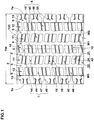
- FIG. 1 illustrates a development view of a tread portion 2 of a heavy duty pneumatic tire 1 in accordance with an embodiment of the present invention.
- the heavy duty pneumatic tire 1 for example, may preferably be embodied as a winter tire.
- the tread portion 2 of the tire 1 is provided with a plurality circumferentially extending main grooves 3, a plurality of axially extending lateral grooves 7 and a plurality of blocks 8 divided by these grooves.
- the main grooves 3 include at least one central main groove 4, at least one shoulder main groove 5 and at least one shoulder narrow groove 6.
- At least one central main groove 4 is arranged proximately to the tire equator C, for example.
- a pair of the central main grooves 4 and 4 are arranged and extend continuously in the circumferential direction of the tire.
- the shoulder main groove 5 is arranged axially outward of the central main groove 3 on each side of the tire equator C. Each of the shoulder main grooves 5 extends continuously in the circumferential direction of the tire.
- groove widths W1 and W2 of the central main groove 4 and the shoulder main groove 5 respectively may be set in a range of from 0.3% to 8.0% of the tread width TW.
- depths of the central main groove 4 and the shoulder main groove 5 may be set in a range of from 10 to 25 mm.
- the tread width TW is defined as the width measured under a normally inflated unloaded condition, as the axial distance between tread edges Te and Te.
- the normally inflated unloaded condition is such that the tire 1 is mounted on a standard wheel rim with a standard pressure but loaded with no tire load.
- the tread edge Te refers to an axially outermost edge of the ground contacting patch of the tread portion 2 which occurs under a normally inflated loaded condition when the camber angle of the tire is zero.
- the normally inflated loaded condition is such that the tire 1 is mounted on the standard wheel rim with the standard pressure and loaded with a standard tire load.
- the standard wheel rim is a wheel rim officially approved or recommended for the tire by standards organizations, wherein the standard wheel rim is the "standard rim” specified in JATMA, the "Measuring Rim” in ETRTO, and the “Design Rim” in TRA or the like, for example.
- the standard pressure is a standard pressure officially approved or recommended for the tire by standards organizations, wherein the standard pressure is the "maximum air pressure" in JATMA, the “Inflation Pressure” in ETRTO, and the maximum pressure given in the "Tire Load Limits at Various Cold Inflation Pressures” table in TRA or the like, for example.
- the standard tire load is a tire load officially approved or recommended for the tire by standards organizations, wherein the standard load is the "maximum load capacity" in JATMA, the “Load Capacity” in ETRTO, and the maximum value given in the above-mentioned table in TRA or the like.
- the shoulder narrow groove 6 is arranged proximate to the tread edge Te and extends straightly and continuously in the circumferential direction of the tire on each side of the tire equator C.
- the shoulder narrow groove 6 has a width W3 which is smaller than those of the central main groove 4 and the shoulder main groove 5.
- the width W3 of the shoulder narrow groove 6, for example, may be set in a range of from 0.10 to 0.15 times the width W2 of the shoulder main groove 5.
- the shoulder narrow groove 6 has a depth smaller than those of the central main groove 4 and the shoulder main groove 5.
- the depth of the shoulder narrow groove 6 may be set in a range of from 5 to 13 mm.
- the tread portion 2 is separated into a central portion 10, a pair of middle portions 11, a pair of inner shoulder portions 12 and a pair of outer shoulder portions 13 by the central main grooves 4, the shoulder main grooves 5 and the shoulder narrow grooves 6.
- FIG. 2 illustrates an enlarged view of the central portion 10.
- the central portion 10 is arranged between the pair of central main groove 4 and 4.
- the central portion 10 is provided with a plurality of central lateral grooves 14 to form a plurality of central blocks 15.
- each of the central lateral grooves extends so that one of the central main grooves 4 communicates with the other.
- each of the central lateral grooves 14 extends in a straight manner, and is inclined in the same direction.
- the central lateral groove 14 has an angle ⁇ 1 in a range of from 3 to 7 degrees with respect to the axial direction of the tire, and a width W6 in a range of from 5 to 10 mm.
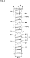
- FIG. 3 illustrates an enlarged view of the central block 15.
- the central block 15 is provided with two axially extending sipes 18 to divide the block 15 into a first end portion 21, a second end portion 22 and a middle portion 24 therebetween.
- the sipe 18 extends along the central lateral grooves 14 (shown in FIG. 2 ). In this embodiment, the respective sipes 18 extend substantially parallel one another. Alternatively, each of the sipes 18 may extend in different angles with respect to the axial direction of the tire.
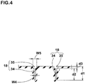
- FIG. 4 illustrates a cross-sectional view taken along a line A-A of FIG. 3 .
- each of the sipes 18 has a depth d1 in a range of from 5 to 10 mm, for example.
- the sipe 18 includes a main portion 34 having a substantially constant width. In this embodiment, an enlarged-width portion 35 is provided on the top portion of the sipe 18.
- the main portion 34 of the sipe 18 extends in a zigzag manner.
- the main portion 34 preferably has a width W4 in a range of from 0.3 to 1.0 mm and a depth d2 in a range of from 4.0 to 9.5 mm.
- the enlarged width portion 35 extends in a straight manner, and more specifically extends in parallel to an amplitude centerline of the enlarged-width portion 35.
- the enlarged-width portion 35 has a width W5 in a range of from 0.5 to 2.0 mm and a depth d3 in a range of from 0.5 to 1.5 mm, for example.
- the main portion 34 of the sipe 18 is located on the center of the enlarged-width portion 35 in a width direction.
- the sipe 18 having the main portion 34 and the enlarged-width portion 35 may exhibit an excellent on-ice performance by sucking up the water on icy road when coming into contact with the road.
- the central block 15 includes the first end portion 21, the second end portion 22 and the middle portion 24 therebetween.
- Each portion 21, 22 and 24 is formed as a substantially plain piece that is not provided with any other grooves nor sipes. These portions 21, 22 and 24 may be useful to suppress uneven wear from the block.
- the middle portion 24 has a top face substantially quadrilateral.
- the middle portion 24 includes a pair of side edges 36 and 36 each facing each of the central main grooves 4, and the pair of side edges 36 and 36 are preferably inclined in the same direction.
- the respective side edges 36 and 36 extend in a straight manner and in parallel one another.
- the middle portion 24 has the top face formed into a parallelogram, for example.
- the first end portion 21 includes a first projected portion 26 that protrudes outwardly in a block-width direction from the middle portion 24 so as to form a steplike side.
- the second end portion 22 includes a second projected portion 27 that protrudes outwardly in an opposite block-width direction to the first projected portion 26 from the middle portion 24 so as to form a steplike side.
- the first projected portion 26 and the second projected portion 27 may provide an excellent on-snow performance by compressing the snow strongly in the corresponding main groove and then shearing it.
- the tire 1 in accordance with the present embodiment may improve on-snow performance while ensuring wet performance by preventing a reduction of void of the main groove.
- the first projected portion 26 includes an edge 37 that faces the central main groove 4.
- the edge 37 includes a long edge 37a inclined in the same direction as the side edge 36 of the middle portion 24 and a short edge 37b inclined in an opposite direction to the side edge 36 of the middle portion 24, and which are connected so as to form a sharp corner 39.
- the second projected portion 27 includes an edge 38 that faces the central main groove 4.
- the edge 38 includes a long edge 38a inclined in the same direction as the side edge 36 of the middle portion 24 and a short edge 38b inclined in an opposite direction to the side edge 36 of the middle portion 24, and which are connected so as to form a sharp corner 39.
- Each of the first projected portion 26 and the second projected portion 27 protrudes outwardly in the block-width direction from the corresponding extension line 32 of the side edge 36 of the middle portion 24.
- the first projected portion 26 has a first maximum protruding length W7 in the axial direction from the extension line 32 of the corresponding side edge 36 of the middle portion 24 in a range of not less than 0.10 times, more preferably not less than 0.15 times, but preferably not more than 0.25 times, more preferably not more than 0.20 times the block width W10 (shown in FIG. 2 ) of the central block 15.
- the second projected portion 27 has a second maximum protruding length W8 in the axial direction from the extension line 32 of the corresponding side edge 36 of the middle portion 24 in a range of not less than 0.10 times, more preferably not less than 0.15 times, but preferably not more than 0.25 times, more preferably not more than 0.20 times the block width W10 (shown in FIG. 2 ) of the central block 15.
- W10 shown in FIG. 2
- the central block 15 includes a first block 41 that has the first maximum protruding length W7 being substantially same as the second maximum protruding length W8.
- a first block 41 may prevent uneven wear from each of the end portions 21 and 22.
- the first end portion 21 further includes a first non-projected portion 28 on an axially opposite side of the first projected portion 26.
- the first non-projected portion 28 is configured not to protrude from the middle portion 24 in the block-width direction.
- the second end portion 22 further includes a second non-projected portion 29 on an axially opposite side of the second projected portion 27.
- the second non-projected portion 29 is configured not to protrude from the middle portion 24 in the block-width direction.
- the first non-projected portion 28 is configured as an edge 33a which faces the central main groove 4 and which is inclined in an opposite direction to the side edge 36 of the middle portion 24.
- the second non-projected portion 29 is configured as an edge 33b which faces the central main groove 4 and which is inclined in an opposite direction to the side edge 36 of the middle portion 24.
- the first non-projected portion 28 and the second non-projected portion 29 may provide edge effect in various directions to improve on-ice performance. Furthermore, these non-projected portions 28 and 29 may ensure sufficient void of the central main groove 4 to improve wet performance.
- the edge 33a of the first end portion 21 is connected to the side edge 36 of the middle portion 24 to form a corner 23 that protrudes toward the central main groove 4.
- the edge 33b of the second end portion 22 is connected to the side edge 36 to form a corner 23 that protrudes toward the central main groove 4.
- the respective corners 23 having a V-shaped edge may be useful to generate large friction against the road such as icy and snowy roads.
- the edge 33a of the first end portion 21 receives a lateral force from the compressed snow in the central main groove 4, the first end portion 21 is elastically deformed so that the first projected portion 26 further protrudes into the central main groove 4. Accordingly, the first projected portion 26 may further compress the snow introduced in the central main groove 4 so that a large shearing force may be obtained. Subsequently, as the first end portion 21 is released from the contact patch, the compressed snow held by the first projected portion 26 will also be released away from the main groove. This action may be useful to prevent clogging the central main groove 4. It is understood for the person skilled in the art that the same advantageous effects may be brought on the second end portion 22.
- FIG. 5 illustrates an enlarged view of the central portion 10 in accordance with another embodiment of the invention.
- the central lateral groove 14 may be provided with a tie-bar 40 in which the bottom is raised.
- the tie-bar 40 may prevent excessive deformation of the central blocks 15 to improve uneven wear resistance.
- FIG. 6 illustrates a cross-sectional view taken along lines B-B of FIG. 5 .
- the central lateral groove 14 has a depth d5 at the tie-bar 40 in a range of from 0.4 to 0.6 times the maximum depth d4 of the central lateral groove 14 in order to improve uneven wear resistance while ensuring on-snow performance as well as wet performance.
- the tie-bar 40 extends along the central lateral groove 14 so as to cross the extension line 32 of one of the side edges 36 of the middle portion 24. Such a tie-bar 40 may be useful to improve edge effect of the first and second projected portions 26 and 27.
- an axial protruding length L1 of the tie-bar 40 from the extension line 32 at the edge 33 of the central block 15 is in a range of not less than 0.2 times, more preferably not less than 0.4 times, but preferably not more than 0.8 times, more preferably not more than 0.6 times an axial width W11 from the corner 39 of the first projected portion 27 to an intersection 43 where the extension line 32 crosses the edge 33 of the central block 15.
- the central portion 10 is preferably formed as a second block row that comprises the first blocks 41 only. This may help to prevent bias traveling of the vehicle.
- a pair of the first projected portions 26 and 26 may be adjacent through one of the central lateral grooves 14 in order to further improve on-snow traction by compressing the snow strongly between adjacent projected portions.
- a pair of the second projected portions 27 and 27 may be adjacent through one of the central lateral grooves 14.
- FIG. 7 illustrates an enlarged view of the left side middle portion 11 illustrated in FIG. 1 .
- the middle portion 11 is formed between the central main groove 4 and the shoulder main groove 5.
- the middle portion 11 is provided with a plurality of middle lateral grooves 44 to form a plurality of middle blocks 45.
- Each of the middle lateral grooves 44 communicates the central main groove 4 with the shoulder main groove 5.
- each of the middle lateral grooves 44 is inclined with respect to the axial direction of the tire in an opposite direction to the central lateral grooves 14 as shown in FIG. 2 .
- each of the middle lateral grooves 44 is arranged in a different location with respect to each of the central lateral grooves 14 in the circumferential direction of the tire.
- Each of the middle blocks 45 is formed as the same configuration of the central block 15 (See FIG. 3 ).
- the middle portion 11 is formed as a first block row that include at least one first block 41 that has the first maximum protruding length W7 being substantially same as the second maximum protruding length W8 and at least one second block 42 that has the first maximum protruding length W7 being different from the second maximum protruding length W8.
- the first block 41 and the second block 42 are arranged alternately in the circumferential direction of the tire in the middle portion 11. This configuration may be helpful to prevent clogging up the main groove by the snow.
- the middle portion 11 formed as the first block row is adjacent to the central portion 10 formed as the second block row. This configuration may further be helpful to prevent clogging up the main groove by the snow by offering the different deformation of the respective blocks during traveling.
- Each middle block 45 is arranged so as to be shifted with a substantially half pitch length in relation to each central block 15 in the circumferential direction of the tire, for example. This configuration may further be helpful to prevent clogging up the main groove 4 by the snow while ensuring drainage performance.
- each of the second blocks 42 has the first maximum protruding length W7 greater than the second maximum protruding length W8.
- the second block 42 is arranged such that the first projected portion 26 protrudes axially outwardly and the second projected portion 27 protrudes axially inwardly.
- the shoulder main groove 5 is subjected to receive a ground contacting pressure lower than that of the central main groove 4.
- the first projected portion 26 having the relatively large maximum protruding length is located in the shoulder main groove 5
- snow shearing force to be generated from the shoulder main groove 5 may relatively be increased so that the respective snow shearing force generated from the shoulder and central main grooves 4 and 5 are balanced.
- the second block 42 has the first maximum protruding length W7 in a range of from not less than 1.65 times, more preferably not less than 1.75 times, but preferably not more than 2.00 times, more preferably not more than 1.90 times the second maximum protruding length W8.
- FIG. 8 illustrates an enlarged view of the left side inner and outer shoulder portions 12 and 13 of FIG. 1 .
- the inner shoulder portion 12 is formed between the shoulder main groove 5 and the shoulder narrow groove 6.
- the inner shoulder portion 12 is provided with a plurality of inner shoulder lateral grooves 47 to form a plurality of inner shoulder blocks 48.
- Each of the inner shoulder lateral grooves 47 communicates the shoulder main groove 5 with the shoulder narrow groove 6.
- the inner shoulder lateral groove 47 is inclined in an opposite direction to the middle lateral groove 44 (shown in FIG. 7 ). Furthermore, each of the inner shoulder lateral grooves 47 is arranged in a different location with respect to each of the middle lateral grooves 44 in the circumferential direction of the tire.
- Each of the inner shoulder blocks 48 is provided with only two sipes 18 to divide it into a pair of end portions 20 and a middle portion 24 therebetween.
- the inner shoulder block 48 only one of the end portions 20 is configured as a projected portion 25 that protrudes outwardly in the block-width direction from the middle portion 24 so as to form a steplike side.
- Such an inner shoulder block 48 may generate a large snow shearing force while ensuring drainage performance of the shoulder main groove 5.
- the outer shoulder portion 13 is formed axially outward of the shoulder narrow groove 6, and is provided with a plurality of outer shoulder lateral grooves 49 to form a plurality of outer shoulder blocks 50.
- Each of the outer shoulder lateral grooves 49 extends along the axial direction of the tire, and arranged in a different location to each inner shoulder lateral groove 47 in the circumferential direction of the tire.
- the outer shoulder lateral groove 49 has a width which enlarges toward the tread edge Te in order to improve wet performance as well as wandering performance.
- the outer shoulder lateral grooves 49 include a first outer shoulder lateral groove 51 having a width and a second outer shoulder lateral groove 52 having a width smaller than that of the first outer shoulder lateral groove 51, and which are alternately arranged in the circumferential direction of the tire.
- the outer shoulder block 50 is provided with at least one sipe 54 that extends axially inwardly from the axially outer side edge 53 of the block without reaching the shoulder narrow groove 6.
- the sipe 54 may be useful to prevent chipping of the outer shoulder block 50 while improving wandering performance.
- the sipe 54 may be bent so as to include a longitudinal portion that extends in the circumferential direction of the tire. Furthermore, at least one sipe 54 may include a pair of sipes 54a and 54b each of which has the longitudinal portion that extends toward an opposite direction each another. This configuration may improve wandering performance by relaxing rigidity of the outer shoulder block 50 as well as cracking resistance of the block by preventing a crack to be generated from the axially inner end of the sipe.
- Heavy duty pneumatic tires having a size of 11R22.5 and the tread pattern shown in FIGS. 1 and 9 were manufactured based on the details of Table 1, and then on-snow performance and wet performance thereof were tested.
- the common specifications of tires and test procedures are as follows.
- test vehicle was made to run on snowy road and then the driver evaluated the traveling performance by his feeling.
- the test results were shown using a score based on Ref. 1 being 100. The larger the value, the better the wet performance is.
- test driver suddenly started the above mentioned test vehicle using the second gear position by engaging its clutch at the timing of a 1,500rpm engine speed on a wet asphalt road with a puddle 5mm deep, and measured the time for traveling to 10m distance.
- the test results were evaluated as the time using an index based on Ref.1 being 100 in Table 1. The smaller the index, the better the wet performance is.
- Example tires in accordance with the present invention can be improved on-snow and wet performance in a well balanced manner.
- Heavy duty pneumatic tires having a size of 11R22.5 and the tread pattern shown in FIGS. 1 and 9 were manufactured based on the details of Table 2, and then on-snow performance, wet performance and wear resistance thereof were tested.
- the common specifications of tires and the test procedures of on-snow and wet performance are the same as the mentioned above.
- the wear resistance test is as follows.
- test vehicle was made to run on a dry asphalt test course for a certain distance and then the amount of average wear of the central blocks was measured. The results were indicated using an index beaded on ref. 1 being 100. The smaller the value, the better the performance is.
Claims (7)
- Schwerlast-Luftreifen (1), umfassend:einen Laufflächenabschnitt (2), der eine Mehrzahl von Blöcken (8) umfasst, die durch eine Mehrzahl von sich in Umfangsrichtung erstreckenden Hauptrillen (3) und eine Mehrzahl von Querrillen (7) getrennt sind;wobei zumindest einer der Blöcke (8) mit zwei sich axial erstreckenden Feinschnitten (18) versehen ist, um den Block (8) in einen ersten Endabschnitt (21), einen zweiten Endabschnitt (22) und einen Mittelabschnitt (24) zwischen dem ersten Endabschnitt (21) und dem zweiten Endabschnitt (22) zu unterteilen;der erste Endabschnitt (21) einen ersten vorstehenden Abschnitt (26) umfasst, der in einer Blockbreitenrichtung von dem Mittelabschnitt (24) nach außen vorsteht, um eine stufenartige Seite zu bilden; undder zweite Endabschnitt (22) einen zweiten vorstehenden Abschnitt (27) umfasst, der in einer entgegengesetzten Blockbreitenrichtung zu dem ersten vorstehenden Abschnitt (26) von dem Mittelabschnitt (24) nach außen vorsteht, um eine stufenartige Seite zu bilden,der erste Endabschnitt (21) einen ersten nicht vorstehenden Abschnitt (28) auf einer axial entgegengesetzten Seite des ersten vorstehenden Abschnitts (26) umfasst, und der erste nicht vorstehende Abschnitt (28) nicht von dem Mittelabschnitt (24) in der Blockbreitenrichtung nach außen vorsteht, undder zweite Endabschnitt (22) ferner einen zweiten nicht vorstehenden Abschnitt (29) auf einer axial entgegengesetzten Seite des zweiten vorstehenden Abschnitts (27) umfasst, und der zweite nicht vorstehende Abschnitt (29) nicht von dem Mittelabschnitt (24) in der Blockbreitenrichtung vorsteht,wobei in einer Draufsicht des Laufflächenabschnitts (2) der Mittelabschnitt (24) ein Paar Seitenkanten (36) aufweist, die jeweils einer jeden der Hauptrillen (3) zugewandt sind, wobei das Paar Seitenkanten (36) in die gleiche Richtung geneigt ist, und ein jeder von dem ersten vorstehenden Abschnitt (26) und dem zweiten vorstehenden Abschnitt (27) eine Kante (37a, 38a) aufweist, die in die gleiche Richtung zu den Seitenkanten (36) geneigt ist,dadurch gekennzeichnet, dassder erste nicht vorstehende Abschnitt (28) in eine entgegengesetzte Richtung zu den Seitenkanten (36) des Mittelabschnitts (24) geneigt ist, und der zweite nicht vorstehende Abschnitt (29) in eine entgegengesetzte Richtung zu den Seitenkanten (36) des Mittelabschnitts (24) geneigt ist.
- Schwerlast-Luftreifen nach Anspruch 1, wobei der erste vorstehende Abschnitt (36) eine erste maximale Vorstandslänge (W7) von einer Verlängerungslinie (32) einer entsprechenden Seitenkante (36) des Mittelabschnitts (24) in einem Bereich vom 0,10- bis 0,25-fachen einer Blockbreite (W10) aufweist, und wobei der zweite vorstehende Abschnitt (27) eine zweite maximale Vorstandslänge (W8) von einer Verlängerungslinie (32) einer entsprechenden Seitenkante (36) des Mittelabschnitts (24) in einem Bereich vom 0,10- bis 0,25-fachen der Blockbreite (W10) aufweist.
- Schwerlast-Luftreifen nach Anspruch 2, wobei die Blöcke (8) einen ersten Block (41) und einen zweiten Block (42) umfassen, wobei der erste Block (41) eine erste maximale Vorstandslänge (W7) aufweist, die im Wesentlichen gleich ist wie die zweite maximale Vorstandslänge (W8), und die maximale Vorstandslänge (W7) des zweiten Blocks (42) sich von der zweiten maximalen Vorstandslänge (W8) unterscheidet.
- Schwerlast-Luftreifen nach Anspruch 3, wobei der Laufflächenabschnitt (2) ferner eine erste Blockreihe umfasst, die den ersten Block (41) und den zweiten Block (42) umfasst, die abwechselnd in einer Umfangsrichtung des Reifens angeordnet sind.
- Schwerlast-Luftreifen nach Anspruch 4, wobei der Laufflächenabschnitt (2) ferner eine zweite Blockreihe umfasst, die nur eine Mehrzahl der ersten Blöcke (41) umfasst, und die erste Blockreihe und die zweite Blockreihe axial benachbart angeordnet sind.
- Schwerlast-Luftreifen nach einem der Ansprüche 1 bis 5,wobei der Mittelabschnitt (24) ein Paar Seitenkanten (36) aufweist, die jeweils einer jeden der Hauptrillen (3) zugewandt sind, wobei zumindest eine der Querrillen (7), die benachbart zu dem ersten Endabschnitt (21) angeordnet ist, mit einem Anbindungssteg (40) versehen ist, in welchem ein Boden erhöht ist, undder Anbindungssteg (40) sich derart entlang der Querrille (7) erstreckt, dass er eine Verlängerungslinie (32) der Seitenkanten (36) des Mittelabschnitts (24), die dem ersten vorstehenden Abschnitt (27) entspricht, kreuzt.
- Schwerlast-Luftreifen nach Anspruch 6,wobei der erste Endabschnitt (21) eine sich gerade erstreckende Querkante (33) aufweist, die einer der Querrillen (7) zugewandt ist,der erste vorstehende Abschnitt (26) in der Blockbreitenrichtung von der Verlängerungslinie (32) nach außen vorsteht, undeine axiale Vorstandslänge (L1) des Anbindungsstegs (40) von der Verlängerungslinie (32) in einem Bereich vom 0,2- bis 0.8-fachen einer axialen Vorstandslänge (W11) des ersten Endabschnitts (21) von der Verlängerungslinie (32) liegt.
Applications Claiming Priority (2)
| Application Number | Priority Date | Filing Date | Title |
|---|---|---|---|
| JP2014240397A JP6134308B2 (ja) | 2014-11-27 | 2014-11-27 | 重荷重用空気入りタイヤ |
| JP2014257824A JP6126572B2 (ja) | 2014-12-19 | 2014-12-19 | 重荷重用空気入りタイヤ |
Publications (2)
| Publication Number | Publication Date |
|---|---|
| EP3025878A1 EP3025878A1 (de) | 2016-06-01 |
| EP3025878B1 true EP3025878B1 (de) | 2018-06-06 |
Family
ID=54542092
Family Applications (1)
| Application Number | Title | Priority Date | Filing Date |
|---|---|---|---|
| EP15194460.0A Active EP3025878B1 (de) | 2014-11-27 | 2015-11-13 | Schwerlastluftreifen |
Country Status (3)
| Country | Link |
|---|---|
| US (1) | US10232669B2 (de) |
| EP (1) | EP3025878B1 (de) |
| CN (1) | CN105644271B (de) |
Families Citing this family (5)
| Publication number | Priority date | Publication date | Assignee | Title |
|---|---|---|---|---|
| USD248574S (en) * | 1976-01-16 | 1978-07-18 | Roger Graham | Bowl for a smoking device |
| JP6367139B2 (ja) * | 2015-02-27 | 2018-08-01 | 東洋ゴム工業株式会社 | 空気入りタイヤ |
| DE102016117816A1 (de) * | 2015-10-06 | 2017-04-06 | Toyo Tire & Rubber Co., Ltd. | Luftreifen |
| EP3378678B1 (de) * | 2017-03-24 | 2021-01-20 | Sumitomo Rubber Industries, Ltd. | Reifen |
| CA181432S (en) * | 2018-01-17 | 2019-03-13 | Continental Reifen Deutschland Gmbh | Tire |
Citations (3)
| Publication number | Priority date | Publication date | Assignee | Title |
|---|---|---|---|---|
| EP0455925A1 (de) * | 1990-05-10 | 1991-11-13 | The Goodyear Tire & Rubber Company | Ganz-Jahr-Lauffläche |
| JP2006188185A (ja) * | 2005-01-07 | 2006-07-20 | Bridgestone Corp | 空気入りタイヤ |
| EP2913204A1 (de) * | 2013-03-06 | 2015-09-02 | The Yokohama Rubber Co., Ltd. | Luftreifen |
Family Cites Families (14)
| Publication number | Priority date | Publication date | Assignee | Title |
|---|---|---|---|---|
| JP2898832B2 (ja) | 1992-09-30 | 1999-06-02 | 株式会社ブリヂストン | 空気入りタイヤ |
| JP4198199B2 (ja) * | 1995-11-10 | 2008-12-17 | 株式会社ブリヂストン | 重荷重用空気入りタイヤ |
| JP3315366B2 (ja) * | 1998-05-13 | 2002-08-19 | オーツタイヤ株式会社 | 空気入りタイヤ |
| DK1412205T3 (da) * | 2001-08-03 | 2006-07-10 | Pirelli | Dæk, der er særligt egnede til snedækket underlag |
| JP3493190B2 (ja) * | 2001-10-15 | 2004-02-03 | 住友ゴム工業株式会社 | 重荷重用空気入りタイヤ |
| JP4392226B2 (ja) * | 2003-11-06 | 2009-12-24 | 住友ゴム工業株式会社 | 空気入りタイヤ |
| JP4445307B2 (ja) | 2004-03-29 | 2010-04-07 | 住友ゴム工業株式会社 | 重荷重用ラジアルタイヤ |
| JP5032829B2 (ja) * | 2006-11-13 | 2012-09-26 | 住友ゴム工業株式会社 | 空気入りタイヤ |
| US9469160B2 (en) * | 2009-01-26 | 2016-10-18 | Bridgestone Corporation | Tire with tread having blocks having cutout portions |
| JP5081264B2 (ja) * | 2010-03-01 | 2012-11-28 | 住友ゴム工業株式会社 | 空気入りタイヤ |
| JP5480869B2 (ja) * | 2011-10-26 | 2014-04-23 | 住友ゴム工業株式会社 | 重荷重用空気入りタイヤ |
| US9757991B2 (en) * | 2013-02-19 | 2017-09-12 | Sumitomo Rubber Industries, Ltd. | Pneumatic tire |
| EP2808179B1 (de) * | 2013-05-27 | 2015-10-21 | Sumitomo Rubber Industries, Ltd. | Luftreifen |
| JP5806707B2 (ja) * | 2013-07-03 | 2015-11-10 | 住友ゴム工業株式会社 | 空気入りタイヤ |
-
2015
- 2015-11-05 US US14/933,690 patent/US10232669B2/en active Active
- 2015-11-13 EP EP15194460.0A patent/EP3025878B1/de active Active
- 2015-11-25 CN CN201510830607.7A patent/CN105644271B/zh active Active
Patent Citations (3)
| Publication number | Priority date | Publication date | Assignee | Title |
|---|---|---|---|---|
| EP0455925A1 (de) * | 1990-05-10 | 1991-11-13 | The Goodyear Tire & Rubber Company | Ganz-Jahr-Lauffläche |
| JP2006188185A (ja) * | 2005-01-07 | 2006-07-20 | Bridgestone Corp | 空気入りタイヤ |
| EP2913204A1 (de) * | 2013-03-06 | 2015-09-02 | The Yokohama Rubber Co., Ltd. | Luftreifen |
Also Published As
| Publication number | Publication date |
|---|---|
| EP3025878A1 (de) | 2016-06-01 |
| US10232669B2 (en) | 2019-03-19 |
| CN105644271A (zh) | 2016-06-08 |
| CN105644271B (zh) | 2019-10-29 |
| US20160152089A1 (en) | 2016-06-02 |
Similar Documents
| Publication | Publication Date | Title |
|---|---|---|
| US10894446B2 (en) | Tire | |
| EP3015287B1 (de) | Luftreifen | |
| US10414211B2 (en) | Pneumatic tire | |
| US10286732B2 (en) | Tire | |
| EP3205516B1 (de) | Luftreifen | |
| EP3025879B1 (de) | Luftreifen | |
| EP3000622B1 (de) | Luftreifen | |
| US10836215B2 (en) | Tire | |
| EP3012119B1 (de) | Luftreifen | |
| EP3000621A2 (de) | Luftreifen | |
| US10703145B2 (en) | Pneumatic tire | |
| EP3135504B1 (de) | Schwerlastreifen | |
| EP3335910B1 (de) | Reifen | |
| EP3025878B1 (de) | Schwerlastluftreifen | |
| JP2017170939A (ja) | 空気入りタイヤ | |
| US10744823B2 (en) | Tire | |
| EP3031624B1 (de) | Luftreifen | |
| JP5282479B2 (ja) | 空気入りタイヤ | |
| EP3321103B1 (de) | Schwerlastreifen |
Legal Events
| Date | Code | Title | Description |
|---|---|---|---|
| PUAI | Public reference made under article 153(3) epc to a published international application that has entered the european phase |
Free format text: ORIGINAL CODE: 0009012 |
|
| AK | Designated contracting states |
Kind code of ref document: A1 Designated state(s): AL AT BE BG CH CY CZ DE DK EE ES FI FR GB GR HR HU IE IS IT LI LT LU LV MC MK MT NL NO PL PT RO RS SE SI SK SM TR |
|
| AX | Request for extension of the european patent |
Extension state: BA ME |
|
| 17P | Request for examination filed |
Effective date: 20161006 |
|
| RBV | Designated contracting states (corrected) |
Designated state(s): AL AT BE BG CH CY CZ DE DK EE ES FI FR GB GR HR HU IE IS IT LI LT LU LV MC MK MT NL NO PL PT RO RS SE SI SK SM TR |
|
| 17Q | First examination report despatched |
Effective date: 20170419 |
|
| GRAP | Despatch of communication of intention to grant a patent |
Free format text: ORIGINAL CODE: EPIDOSNIGR1 |
|
| INTG | Intention to grant announced |
Effective date: 20180221 |
|
| GRAS | Grant fee paid |
Free format text: ORIGINAL CODE: EPIDOSNIGR3 |
|
| GRAA | (expected) grant |
Free format text: ORIGINAL CODE: 0009210 |
|
| AK | Designated contracting states |
Kind code of ref document: B1 Designated state(s): AL AT BE BG CH CY CZ DE DK EE ES FI FR GB GR HR HU IE IS IT LI LT LU LV MC MK MT NL NO PL PT RO RS SE SI SK SM TR |
|
| REG | Reference to a national code |
Ref country code: GB Ref legal event code: FG4D |
|
| REG | Reference to a national code |
Ref country code: CH Ref legal event code: EP Ref country code: AT Ref legal event code: REF Ref document number: 1005658 Country of ref document: AT Kind code of ref document: T Effective date: 20180615 |
|
| REG | Reference to a national code |
Ref country code: IE Ref legal event code: FG4D |
|
| REG | Reference to a national code |
Ref country code: DE Ref legal event code: R096 Ref document number: 602015011733 Country of ref document: DE |
|
| REG | Reference to a national code |
Ref country code: NL Ref legal event code: MP Effective date: 20180606 |
|
| REG | Reference to a national code |
Ref country code: LT Ref legal event code: MG4D |
|
| PG25 | Lapsed in a contracting state [announced via postgrant information from national office to epo] |
Ref country code: FI Free format text: LAPSE BECAUSE OF FAILURE TO SUBMIT A TRANSLATION OF THE DESCRIPTION OR TO PAY THE FEE WITHIN THE PRESCRIBED TIME-LIMIT Effective date: 20180606 Ref country code: BG Free format text: LAPSE BECAUSE OF FAILURE TO SUBMIT A TRANSLATION OF THE DESCRIPTION OR TO PAY THE FEE WITHIN THE PRESCRIBED TIME-LIMIT Effective date: 20180906 Ref country code: LT Free format text: LAPSE BECAUSE OF FAILURE TO SUBMIT A TRANSLATION OF THE DESCRIPTION OR TO PAY THE FEE WITHIN THE PRESCRIBED TIME-LIMIT Effective date: 20180606 Ref country code: CY Free format text: LAPSE BECAUSE OF FAILURE TO SUBMIT A TRANSLATION OF THE DESCRIPTION OR TO PAY THE FEE WITHIN THE PRESCRIBED TIME-LIMIT Effective date: 20180606 Ref country code: SE Free format text: LAPSE BECAUSE OF FAILURE TO SUBMIT A TRANSLATION OF THE DESCRIPTION OR TO PAY THE FEE WITHIN THE PRESCRIBED TIME-LIMIT Effective date: 20180606 Ref country code: ES Free format text: LAPSE BECAUSE OF FAILURE TO SUBMIT A TRANSLATION OF THE DESCRIPTION OR TO PAY THE FEE WITHIN THE PRESCRIBED TIME-LIMIT Effective date: 20180606 Ref country code: NO Free format text: LAPSE BECAUSE OF FAILURE TO SUBMIT A TRANSLATION OF THE DESCRIPTION OR TO PAY THE FEE WITHIN THE PRESCRIBED TIME-LIMIT Effective date: 20180906 |
|
| PG25 | Lapsed in a contracting state [announced via postgrant information from national office to epo] |
Ref country code: HR Free format text: LAPSE BECAUSE OF FAILURE TO SUBMIT A TRANSLATION OF THE DESCRIPTION OR TO PAY THE FEE WITHIN THE PRESCRIBED TIME-LIMIT Effective date: 20180606 Ref country code: RS Free format text: LAPSE BECAUSE OF FAILURE TO SUBMIT A TRANSLATION OF THE DESCRIPTION OR TO PAY THE FEE WITHIN THE PRESCRIBED TIME-LIMIT Effective date: 20180606 Ref country code: GR Free format text: LAPSE BECAUSE OF FAILURE TO SUBMIT A TRANSLATION OF THE DESCRIPTION OR TO PAY THE FEE WITHIN THE PRESCRIBED TIME-LIMIT Effective date: 20180907 Ref country code: LV Free format text: LAPSE BECAUSE OF FAILURE TO SUBMIT A TRANSLATION OF THE DESCRIPTION OR TO PAY THE FEE WITHIN THE PRESCRIBED TIME-LIMIT Effective date: 20180606 |
|
| REG | Reference to a national code |
Ref country code: AT Ref legal event code: MK05 Ref document number: 1005658 Country of ref document: AT Kind code of ref document: T Effective date: 20180606 |
|
| PG25 | Lapsed in a contracting state [announced via postgrant information from national office to epo] |
Ref country code: NL Free format text: LAPSE BECAUSE OF FAILURE TO SUBMIT A TRANSLATION OF THE DESCRIPTION OR TO PAY THE FEE WITHIN THE PRESCRIBED TIME-LIMIT Effective date: 20180606 |
|
| PG25 | Lapsed in a contracting state [announced via postgrant information from national office to epo] |
Ref country code: EE Free format text: LAPSE BECAUSE OF FAILURE TO SUBMIT A TRANSLATION OF THE DESCRIPTION OR TO PAY THE FEE WITHIN THE PRESCRIBED TIME-LIMIT Effective date: 20180606 Ref country code: SK Free format text: LAPSE BECAUSE OF FAILURE TO SUBMIT A TRANSLATION OF THE DESCRIPTION OR TO PAY THE FEE WITHIN THE PRESCRIBED TIME-LIMIT Effective date: 20180606 Ref country code: RO Free format text: LAPSE BECAUSE OF FAILURE TO SUBMIT A TRANSLATION OF THE DESCRIPTION OR TO PAY THE FEE WITHIN THE PRESCRIBED TIME-LIMIT Effective date: 20180606 Ref country code: PL Free format text: LAPSE BECAUSE OF FAILURE TO SUBMIT A TRANSLATION OF THE DESCRIPTION OR TO PAY THE FEE WITHIN THE PRESCRIBED TIME-LIMIT Effective date: 20180606 Ref country code: CZ Free format text: LAPSE BECAUSE OF FAILURE TO SUBMIT A TRANSLATION OF THE DESCRIPTION OR TO PAY THE FEE WITHIN THE PRESCRIBED TIME-LIMIT Effective date: 20180606 Ref country code: AT Free format text: LAPSE BECAUSE OF FAILURE TO SUBMIT A TRANSLATION OF THE DESCRIPTION OR TO PAY THE FEE WITHIN THE PRESCRIBED TIME-LIMIT Effective date: 20180606 Ref country code: IS Free format text: LAPSE BECAUSE OF FAILURE TO SUBMIT A TRANSLATION OF THE DESCRIPTION OR TO PAY THE FEE WITHIN THE PRESCRIBED TIME-LIMIT Effective date: 20181006 |
|
| PG25 | Lapsed in a contracting state [announced via postgrant information from national office to epo] |
Ref country code: SM Free format text: LAPSE BECAUSE OF FAILURE TO SUBMIT A TRANSLATION OF THE DESCRIPTION OR TO PAY THE FEE WITHIN THE PRESCRIBED TIME-LIMIT Effective date: 20180606 Ref country code: IT Free format text: LAPSE BECAUSE OF FAILURE TO SUBMIT A TRANSLATION OF THE DESCRIPTION OR TO PAY THE FEE WITHIN THE PRESCRIBED TIME-LIMIT Effective date: 20180606 |
|
| REG | Reference to a national code |
Ref country code: DE Ref legal event code: R097 Ref document number: 602015011733 Country of ref document: DE |
|
| PLBE | No opposition filed within time limit |
Free format text: ORIGINAL CODE: 0009261 |
|
| STAA | Information on the status of an ep patent application or granted ep patent |
Free format text: STATUS: NO OPPOSITION FILED WITHIN TIME LIMIT |
|
| 26N | No opposition filed |
Effective date: 20190307 |
|
| PG25 | Lapsed in a contracting state [announced via postgrant information from national office to epo] |
Ref country code: SI Free format text: LAPSE BECAUSE OF FAILURE TO SUBMIT A TRANSLATION OF THE DESCRIPTION OR TO PAY THE FEE WITHIN THE PRESCRIBED TIME-LIMIT Effective date: 20180606 Ref country code: DK Free format text: LAPSE BECAUSE OF FAILURE TO SUBMIT A TRANSLATION OF THE DESCRIPTION OR TO PAY THE FEE WITHIN THE PRESCRIBED TIME-LIMIT Effective date: 20180606 |
|
| REG | Reference to a national code |
Ref country code: CH Ref legal event code: PL |
|
| PG25 | Lapsed in a contracting state [announced via postgrant information from national office to epo] |
Ref country code: MC Free format text: LAPSE BECAUSE OF FAILURE TO SUBMIT A TRANSLATION OF THE DESCRIPTION OR TO PAY THE FEE WITHIN THE PRESCRIBED TIME-LIMIT Effective date: 20180606 Ref country code: LU Free format text: LAPSE BECAUSE OF NON-PAYMENT OF DUE FEES Effective date: 20181113 |
|
| REG | Reference to a national code |
Ref country code: BE Ref legal event code: MM Effective date: 20181130 |
|
| REG | Reference to a national code |
Ref country code: IE Ref legal event code: MM4A |
|
| PG25 | Lapsed in a contracting state [announced via postgrant information from national office to epo] |
Ref country code: CH Free format text: LAPSE BECAUSE OF NON-PAYMENT OF DUE FEES Effective date: 20181130 Ref country code: LI Free format text: LAPSE BECAUSE OF NON-PAYMENT OF DUE FEES Effective date: 20181130 |
|
| PG25 | Lapsed in a contracting state [announced via postgrant information from national office to epo] |
Ref country code: IE Free format text: LAPSE BECAUSE OF NON-PAYMENT OF DUE FEES Effective date: 20181113 |
|
| PG25 | Lapsed in a contracting state [announced via postgrant information from national office to epo] |
Ref country code: AL Free format text: LAPSE BECAUSE OF FAILURE TO SUBMIT A TRANSLATION OF THE DESCRIPTION OR TO PAY THE FEE WITHIN THE PRESCRIBED TIME-LIMIT Effective date: 20180606 Ref country code: BE Free format text: LAPSE BECAUSE OF NON-PAYMENT OF DUE FEES Effective date: 20181130 |
|
| PG25 | Lapsed in a contracting state [announced via postgrant information from national office to epo] |
Ref country code: MT Free format text: LAPSE BECAUSE OF NON-PAYMENT OF DUE FEES Effective date: 20181113 |
|
| PG25 | Lapsed in a contracting state [announced via postgrant information from national office to epo] |
Ref country code: TR Free format text: LAPSE BECAUSE OF FAILURE TO SUBMIT A TRANSLATION OF THE DESCRIPTION OR TO PAY THE FEE WITHIN THE PRESCRIBED TIME-LIMIT Effective date: 20180606 |
|
| PG25 | Lapsed in a contracting state [announced via postgrant information from national office to epo] |
Ref country code: PT Free format text: LAPSE BECAUSE OF FAILURE TO SUBMIT A TRANSLATION OF THE DESCRIPTION OR TO PAY THE FEE WITHIN THE PRESCRIBED TIME-LIMIT Effective date: 20180606 |
|
| PG25 | Lapsed in a contracting state [announced via postgrant information from national office to epo] |
Ref country code: MK Free format text: LAPSE BECAUSE OF NON-PAYMENT OF DUE FEES Effective date: 20180606 Ref country code: HU Free format text: LAPSE BECAUSE OF FAILURE TO SUBMIT A TRANSLATION OF THE DESCRIPTION OR TO PAY THE FEE WITHIN THE PRESCRIBED TIME-LIMIT; INVALID AB INITIO Effective date: 20151113 |
|
| GBPC | Gb: european patent ceased through non-payment of renewal fee |
Effective date: 20191113 |
|
| PG25 | Lapsed in a contracting state [announced via postgrant information from national office to epo] |
Ref country code: GB Free format text: LAPSE BECAUSE OF NON-PAYMENT OF DUE FEES Effective date: 20191113 |
|
| P01 | Opt-out of the competence of the unified patent court (upc) registered |
Effective date: 20230510 |
|
| PGFP | Annual fee paid to national office [announced via postgrant information from national office to epo] |
Ref country code: FR Payment date: 20230929 Year of fee payment: 9 |
|
| PGFP | Annual fee paid to national office [announced via postgrant information from national office to epo] |
Ref country code: DE Payment date: 20230929 Year of fee payment: 9 |