EP3029254A1 - Variabler Anschlag - Google Patents
Variabler Anschlag Download PDFInfo
- Publication number
- EP3029254A1 EP3029254A1 EP14196283.7A EP14196283A EP3029254A1 EP 3029254 A1 EP3029254 A1 EP 3029254A1 EP 14196283 A EP14196283 A EP 14196283A EP 3029254 A1 EP3029254 A1 EP 3029254A1
- Authority
- EP
- European Patent Office
- Prior art keywords
- stop
- fitting
- door
- fitting device
- designed
- Prior art date
- Legal status (The legal status is an assumption and is not a legal conclusion. Google has not performed a legal analysis and makes no representation as to the accuracy of the status listed.)
- Withdrawn
Links
- 239000011521 glass Substances 0.000 claims abstract description 53
- 230000008878 coupling Effects 0.000 description 12
- 238000010168 coupling process Methods 0.000 description 12
- 238000005859 coupling reaction Methods 0.000 description 12
- 238000006073 displacement reaction Methods 0.000 description 3
- 238000003801 milling Methods 0.000 description 2
- 238000010276 construction Methods 0.000 description 1
- 230000001419 dependent effect Effects 0.000 description 1
- 238000003780 insertion Methods 0.000 description 1
- 230000037431 insertion Effects 0.000 description 1
Images


Classifications
-
- E—FIXED CONSTRUCTIONS
- E05—LOCKS; KEYS; WINDOW OR DOOR FITTINGS; SAFES
- E05F—DEVICES FOR MOVING WINGS INTO OPEN OR CLOSED POSITION; CHECKS FOR WINGS; WING FITTINGS NOT OTHERWISE PROVIDED FOR, CONCERNED WITH THE FUNCTIONING OF THE WING
- E05F7/00—Accessories for wings not provided for in other groups of this subclass
- E05F7/005—Aligning devices for wings
-
- E—FIXED CONSTRUCTIONS
- E05—LOCKS; KEYS; WINDOW OR DOOR FITTINGS; SAFES
- E05D—HINGES OR SUSPENSION DEVICES FOR DOORS, WINDOWS OR WINGS
- E05D5/00—Construction of single parts, e.g. the parts for attachment
- E05D5/02—Parts for attachment, e.g. flaps
- E05D5/0246—Parts for attachment, e.g. flaps for attachment to glass panels
-
- E—FIXED CONSTRUCTIONS
- E05—LOCKS; KEYS; WINDOW OR DOOR FITTINGS; SAFES
- E05Y—INDEXING SCHEME ASSOCIATED WITH SUBCLASSES E05D AND E05F, RELATING TO CONSTRUCTION ELEMENTS, ELECTRIC CONTROL, POWER SUPPLY, POWER SIGNAL OR TRANSMISSION, USER INTERFACES, MOUNTING OR COUPLING, DETAILS, ACCESSORIES, AUXILIARY OPERATIONS NOT OTHERWISE PROVIDED FOR, APPLICATION THEREOF
- E05Y2201/00—Constructional elements; Accessories therefor
- E05Y2201/20—Brakes; Disengaging means; Holders; Stops; Valves; Accessories therefor
- E05Y2201/224—Stops
-
- E—FIXED CONSTRUCTIONS
- E05—LOCKS; KEYS; WINDOW OR DOOR FITTINGS; SAFES
- E05Y—INDEXING SCHEME ASSOCIATED WITH SUBCLASSES E05D AND E05F, RELATING TO CONSTRUCTION ELEMENTS, ELECTRIC CONTROL, POWER SUPPLY, POWER SIGNAL OR TRANSMISSION, USER INTERFACES, MOUNTING OR COUPLING, DETAILS, ACCESSORIES, AUXILIARY OPERATIONS NOT OTHERWISE PROVIDED FOR, APPLICATION THEREOF
- E05Y2600/00—Mounting or coupling arrangements for elements provided for in this subclass
- E05Y2600/10—Adjustable
-
- E—FIXED CONSTRUCTIONS
- E05—LOCKS; KEYS; WINDOW OR DOOR FITTINGS; SAFES
- E05Y—INDEXING SCHEME ASSOCIATED WITH SUBCLASSES E05D AND E05F, RELATING TO CONSTRUCTION ELEMENTS, ELECTRIC CONTROL, POWER SUPPLY, POWER SIGNAL OR TRANSMISSION, USER INTERFACES, MOUNTING OR COUPLING, DETAILS, ACCESSORIES, AUXILIARY OPERATIONS NOT OTHERWISE PROVIDED FOR, APPLICATION THEREOF
- E05Y2800/00—Details, accessories and auxiliary operations not otherwise provided for
- E05Y2800/15—Applicability
- E05Y2800/16—Applicable on combinations of fixed and movable wings
- E05Y2800/162—Applicable on combinations of fixed and movable wings the wings being coplanar when the movable wing is in the closed position
-
- E—FIXED CONSTRUCTIONS
- E05—LOCKS; KEYS; WINDOW OR DOOR FITTINGS; SAFES
- E05Y—INDEXING SCHEME ASSOCIATED WITH SUBCLASSES E05D AND E05F, RELATING TO CONSTRUCTION ELEMENTS, ELECTRIC CONTROL, POWER SUPPLY, POWER SIGNAL OR TRANSMISSION, USER INTERFACES, MOUNTING OR COUPLING, DETAILS, ACCESSORIES, AUXILIARY OPERATIONS NOT OTHERWISE PROVIDED FOR, APPLICATION THEREOF
- E05Y2800/00—Details, accessories and auxiliary operations not otherwise provided for
- E05Y2800/67—Materials; Strength alteration thereof
- E05Y2800/672—Glass
Definitions
- the present invention relates to a fitting device for a door element, in particular for a door element of a glass door system, according to the preamble of claim 1, comprising a first fitting element and a second fitting element, which forming a clamping area for the door element are connected to one another while clamping the door element, and wherein between the fitting elements a relative to the fitting elements and to the recorded in the Einspann Silver door element adjusting element is arranged, which is non-positively and / or positively coupled with at least one of the fitting elements.
- fitting devices are mounted both on doors, and on windows and should have a visually advantageous appearance within a fitting system.
- the fitting devices usually consist of two fitting elements, between which the door element, for example side and / or upper parts of a glass door system are clamped.
- the door elements are held by the fitting devices according to predetermined standards and fasteners that are guided by the fitting devices through recesses, for example in the form of holes and recesses in the door element.
- recesses for example in the form of holes and recesses in the door element.
- the corner regions of the door elements are cut along the contour thereof.
- the fitting elements can come to rest, and form over the cutout of the door element a free space, which serves, for example, to over a Connecting element, which is part of the fitting device, and which is preferably arranged between the fitting elements, designed as a pivoting and / or swing door element on a pivot point and / or an axis can be arranged or mounted.
- the known fitting devices are used to install glass doors or glass door elements in a glass door system in which the tops, as well as the side panels made of glass. In this case, thicker glasses are usually used for the side or upper parts of the glass door system than for the glass door element connected thereto.
- the object of the present invention to overcome the above-described disadvantages of the prior art.
- the inventive fitting device for a door element in particular for a door element of a glass door system, includes the technical teaching that a stop is arranged on the adjusting element.
- This solution has the advantage that displaceable via the arranged between the fitting elements and to the recorded in the clamping area door element adjustment also arranged on the adjusting stop relative to the fitting elements and to the recorded in the Einspann Scheme door element or for a fine adjustment within the fitting device is relocatable.
- the stop with the adjusting element can both at least partially in the direction parallel to the longitudinal extension of the fitting elements, ie move parallel to the surfaces of the clamped in the clamping between the fitting elements glass door element.
- the stop can be moved towards the center of the glass or outwards, ie orthogonally to the glass surfaces in order to align the stop on the door element depending on the circumstances. Due to the arrangement of the stop on the adjusting element, the stop can be displaced or adjusted with the adjusting element so that at least one surface of the glass door element with at least one surface of the side parts or the upper part of the door system lie on a plane without offset.
- the adjusting element is designed integrally with the stop.
- An integral embodiment is to be understood both an integral configuration of the adjustment with the stop, as well as a construction or assembly group or - unit, which consists of the adjustment and the stop.
- the adjustment can be understood in the context of the present invention as the stop. If the stop is configured as an adjusting element, it can be positively and / or positively coupled directly to at least one of the fitting elements, or the stop configured as an adjusting element can be connected to at least one of the fitting elements via an additional adjusting element or on a connecting element operatively connected to this adjusting element. and / or be positively coupled.
- the stop can advantageously be coupled to the adjustment element at least in a form-fitting manner.
- the stopper can also be positively coupled to the adjusting element.
- fasteners in the form of screws, rivets or equivalent fasteners serve.
- the stop is displaceable relative to the adjusting element.
- the position of the stop in the fitting device can be changed or adjusted again by the relative displaceability between the adjustment and the stop.
- the level or angular offset between the door element and the glass door system in the region of the stop can be adjusted both via the adjustable between the fitting elements and relative to the door element adjustment and complementally displaceable by the adjusting element as an additional adjustment stop. Accordingly, with the fitting device according to the invention, namely here in particular with the displaceable relative to the adjustment stop the adjustment range can be further expanded.
- the adjusting element designed as a holding element that is in operative connection with a connecting element, with which the stop non-positively and / or positively coupled.
- a connecting element for aligning the door elements, d. H. to compensate for an angular offset between a glass door and the side panels and / or the upper part of a door system can advantageously serve as a T-piece ausgestaltetes retaining element.
- the holding element preferably has surfaces which are guided in recesses of the fitting elements, and on which support sections are designed which provide a sufficiently large support to the operatively connected to the holding element connecting element and the abutment arranged thereon in a tolerance range of about 10 mm 20 mm from or to the glass center of the clamped between the fitting elements glass door element to move.
- the holding element preferably has a T-shaped design, with two surfaces which are orthogonal to one another.
- the adjusting element designed as a holding element is preferably provided on both sides in both fitting elements via one of the surfaces, for example in the recess designed as a groove in the fitting elements or Guide out, and arrives in a particularly preferred manner to both hardware elements for non-positive and / or positive fit plant.
- the adjusting element configured as a T-shaped retaining element has the further advantage that it can not only be displaced or guided parallel in the longitudinal direction to the fitting elements in the guide of the fitting elements, but also in the aforementioned tolerance range between the fitting elements, ie on the one hand or on the other Fitting element is displaced or displaced.
- a level or angular offset between the side panels or the upper part of a door system and the glass door can be adjusted via the designed as a holding element adjustment, but the stop can also be moved parallel to the fitting elements, whereby the stop area for the glass door in addition can be adjusted.
- the stop via a connecting element, which is operatively connected to the adjusting element designed as a holding element, with the adjusting force and / or positively coupled.
- the connecting element is advantageously designed such that by at least partially insertion of the stop in the connecting element, d. H.
- the coupling can be configured advantageously as a dovetail coupling.
- the stop can be coupled in an advantageously additional non-positively with the connecting element.
- the connecting element is preferably at least one fastener, which may be configured, for example in the form of a screw.
- At least one recess in the form of a bore or a milling configured in the fastening element which has, for example, an external thread, non-positively and / or positively engages, or passes through the recess and engages in a on the connecting element or the Adjusting element configured bore with internal thread, which is adapted to the external thread of the fastener, engages positively and positively.
- the adjustment is configured as an angle or elbow.
- the stop is designed as an angle or elbow.
- the angle element or elbow on two mutually orthogonal flanks, wherein one flank to the arrangement of the stop, and in particular for the arrangement of a stopper, and the other edge for non-positive and / or positive coupling with the connecting element or with the fitting element is used.
- the recess in the form of a bore or a milling configured on the edge, which serves for non-positive and / or positive coupling with the connecting element or the fitting element through which engages the fastener or on which the fastener positively and positively coupled is.
- the adjusting element which is designed as an angle element, and which is non-positively and / or positively coupled with at least one of the fitting elements, a U-shaped profile.
- the U-shaped angle element passes in a preferred manner at least partially on one of the fitting elements of the fitting device for engagement.
- the adjusting element ie also for fixing the integral with the adjusting stop or the force-locked with the adjusting and / or positively locking stop is at least on one of the parallel edges of the U-profile designed as a threaded element, and particularly preferred designed two threaded holes, engage in the designed as fasteners threaded pins that press when screwing into the threaded holes with its free end against the outer wall of the fitting elements and thus fix the adjustment and thus the stop on the fitting, and in particular on at least one of the fitting elements , Since here the fixation of the adjusting element by tightening, ie by the contact pressure of the threaded holes screwed through the threaded holes, is a stepless adjustability, or a fine adjustment of the stop in the attack area with the fitting device according to the invention carried out.
- the stop or the adjustment element designed integrally with the stop which is designed as an angle piece with two mutually orthogonal flanks, preferably has a recess in the form of an oblong hole.
- the fastening element which serves for non-positive coupling between the stop or the stop configured as an adjustment element and the connecting element, preferably engages in a formed on the connecting element bore with internal thread, which is adapted to the external thread of the fastening element.
- FIG. 1 shows a first embodiment of a fitting device 1 according to the invention for a door element 2, in particular for a glass door element of a glass door system.
- the fitting device 1 comprises a first fitting element 3 and a second fitting element 4.
- the fitting elements 3 and 4 form a clamping region 5 for the door element 2.
- Under clamping of the door element 2, the fitting elements 3 and 4 can be connected to one another.
- an adjustment 6 is arranged between the fitting elements 3 and 4, an adjustment 6 is arranged.
- the adjusting element 6 is displaceable parallel to the fitting elements 3 and 4 and to the door element 2 clamped in the clamping area 5 between the fitting elements 3 and 4.
- the adjusting element 6 between the fitting elements 3 and 4 ie towards the glass center AA towards or outwardly displaceable (s. FIGS.
- the setting element is designed as a U-shaped angle element 6.1 with three flanks.
- the edge 7 of the configured as a U-shaped angle element 6.1 adjusting element 6 two recesses 8 are designed in the form of threaded holes through the fasteners 9 in Take the form of grub screws.
- the fastening elements 9 designed as threaded pins the adjusting element 6 and the stop 10 arranged on the adjusting element 6 can be adjustably fixed to the fitting element 3 of the fitting device 1.
- the stop 10 is configured integrally with the adjusting element 6 configured as an angle element 6.1, namely in the form of a planar element 11 arranged orthogonally to the flank 7 of the adjusting element 6 configured as an angle element 6.1, at the free end of which a stopper 12 is arranged.
- the thus configured fitting device 1 with the arranged on the adjusting element 6 stopper 10 is preferably used for mounting on a designed as a skylight or top door element 2 or on a designed as a side part of a door system door element 2.
- a glass door, which on the stop 10 of the fitting device. 1 abuts, is preferably mounted on a rotation axis within the door system.
- the fitting device 1 is preferably arranged at the corner region of the door system, ie here at the corner region of the door element 2, which may be an upper part or a side part of the door system.
- the arrangement of the fitting device 1 with the stop 10 arranged thereon advantageously takes place at the upper corner region of the door system, which lies approximately diagonally to the lower corner region, in which the glass door is arranged on a rotation axis, the glass door being arranged between the two corner regions and at the arranged in the upper corner area stop 10 comes into contact or is stopped at the stopper 12.
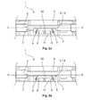
- FIGS. 2a and 2b show the fitting device FIG. 1 in a top view from below.
- the setting of the stop 10 in the in the FIG. 2a shown fitting device 1 is used in comparison to the setting of the stop 10 in the in the FIG. 2b illustrated fitting device 1 to adjust a glass door with a lower glass thickness to the door system and in particular to the glass thickness of the clamped in the fitting door element 2 to compensate for the angular offset.
- To adjust the stop 10 via the adjusting element 6, namely to compensate for the angular offset between the door element 2 and the glass door is in FIG.
- the adjusting element 6 is shifted to the glass center AA of the door element 2 and is fixed in this position, namely towards the glass center AA, via the fastening elements 9 which engage as threaded pins through the recesses 8 designed as threaded bores.
- the stopper 10 is displaced outwards from the center of the glass AA, namely as shown here FIG. 2b shown shifted down. In this position, the adjusting element 6 and arranged on the adjusting element 6 stop 10 is fixed on the fitting element 3 designed as threaded fasteners.
- the adjusting element 6 is designed as a holding element 13 which is parallel to the fitting elements 3 and 4 of the fitting device 1 and between the fitting elements 3 and 4, namely orthogonal to the surface of the clamped between the fitting elements 3 and 4 door element 2 is movable or displaced.
- the adjusting element 6 is operatively connected via pins 14 with a connecting element 15.
- the connecting element 15 in this case has a recess 16, in which an edge of the 7.1 designed as an angle 6.2 stop 10th positively engages. In the edge of the 7.1 designed as an angle 6.2 stop 10, a recess 8 is designed in the form of a slot.
- the connecting element 15 may also be formed integrally, ie integrally with the stop 10 designed as an angle piece 6.2.
- the connecting element 15 offers in a two-part design of elbow 6.2 and connecting element 15 of the advantage that both via the holding element 13, which serves here as a first adjusting element 6, an adjustment of the stop 10 takes place.
- a second adjusting 6 configured with an even larger adjustment range can be formed by the relative displacement between the designed as an angle 6.2 stop 10 and the connecting element 15 .
- an even greater angular offset between two door elements ie an even greater difference between the glass thicknesses of two door elements, can be compensated for in addition via the stop 10 designed as an angle piece 6.2 with a recess 8 formed in the edge 7.1.
- FIGS. 4a and 4b Show is also in the FIG. 3 illustrated fitting device 1, here in particular the stop 10 via the adjusting element 6, namely here on the integrally formed with the stop 10 adjustment 6 by means of configured as a slot recess 8 relative to the glass center AA of the door element 2 between the fitting elements 3 and 4 slidably.
- the stop 10 with the sheet-like element 11 via the slot configured recess 8 is displaced to the stop on the head of the fastener 9 configured as a screw in the direction of the glass center point AA of the door element 2.
- FIG. 4a illustrated setting of the stop 10, which is set to a glass door with a low glass thickness, as in FIG. 4b shown, the stop 10, in particular the arranged on the stop 10 stopper 12 is shifted from the glass center AA down, wherein the configured as a screw fastener 9 is approximately in the middle of the elongated hole configured recess 8.
- the stopper 10 can also be made via the configured as a holding element 13 adjustment 6, namely by its displacement between the fitting elements 3 and 4 of the fitting device 1 adjustment of the stop 10.
- the configured as an angle 6.2 adjusting element 6, which is configured integrally with the stop 10 in addition to the designed as a holding element 13 adjustment 6 of the adjustment of the stop can be further expanded, ie in particular a displacement of the stopper 10 and in particular of the stopper 12th away from the glass center AA and thus the distance between the stopper 12 and the glass center AA are still increased.
- the stop 10 can be moved parallel to the fitting elements 3 and 4
- the door element 2 clamped between the fitting elements 3 and 4 of the fitting device 1 a designed as a skylight upper part and / or a side part of a glass door system, wherein between the upper part and the side part or the side panels a glass door is connected.
Landscapes
- Engineering & Computer Science (AREA)
- Mechanical Engineering (AREA)
- Securing Of Glass Panes Or The Like (AREA)
- Surface Treatment Of Glass (AREA)
Priority Applications (2)
| Application Number | Priority Date | Filing Date | Title |
|---|---|---|---|
| EP14196283.7A EP3029254A1 (de) | 2014-12-04 | 2014-12-04 | Variabler Anschlag |
| CN201510323894.2A CN105672813B (zh) | 2014-12-04 | 2015-06-12 | 可变的止挡 |
Applications Claiming Priority (1)
| Application Number | Priority Date | Filing Date | Title |
|---|---|---|---|
| EP14196283.7A EP3029254A1 (de) | 2014-12-04 | 2014-12-04 | Variabler Anschlag |
Publications (1)
| Publication Number | Publication Date |
|---|---|
| EP3029254A1 true EP3029254A1 (de) | 2016-06-08 |
Family
ID=52102480
Family Applications (1)
| Application Number | Title | Priority Date | Filing Date |
|---|---|---|---|
| EP14196283.7A Withdrawn EP3029254A1 (de) | 2014-12-04 | 2014-12-04 | Variabler Anschlag |
Country Status (2)
| Country | Link |
|---|---|
| EP (1) | EP3029254A1 (zh) |
| CN (1) | CN105672813B (zh) |
Citations (4)
| Publication number | Priority date | Publication date | Assignee | Title |
|---|---|---|---|---|
| EP0035143A2 (de) * | 1980-03-04 | 1981-09-09 | VEGLA Vereinigte Glaswerke GmbH | Drehbeschlag für Ganzglastüren |
| DE8536840U1 (de) * | 1985-10-25 | 1990-02-08 | Società Italiana Progetti S.r.l., Magenta, Mailand/Milano | Beschlag für einen Ganzglasflügel, insbesondere für Ganzglastüren, Ganzglasfenster, Ganzglasoberlichter und Ganzglasvitrinenscheiben |
| EP0362044A1 (fr) * | 1988-09-27 | 1990-04-04 | O. MUSTAD & FILS - S.A. | Dispositif polyvalent à insert modulaire et réversible pour la fixation d'ensembles verriers, notamment impostes ou dormants et portes |
| DE102009022802A1 (de) * | 2009-05-27 | 2010-12-02 | Dorma Gmbh + Co. Kg | Schwenkwinkeltoleranzausgleichsbeschlag für eine Pendeltür |
Family Cites Families (4)
| Publication number | Priority date | Publication date | Assignee | Title |
|---|---|---|---|---|
| DE3606277A1 (de) * | 1986-02-27 | 1987-09-03 | Ver Glaswerke Gmbh | Oberlichtbeschlag fuer ganzglastueranlagen |
| CN2440101Y (zh) * | 2000-07-21 | 2001-07-25 | 好信有限公司 | 无框式玻璃门的上包角 |
| CN2854022Y (zh) * | 2005-11-21 | 2007-01-03 | 赵挺开 | 玻璃门的门夹 |
| AT506318B1 (de) * | 2008-04-02 | 2009-08-15 | Weissofner Claus | Türe, insbesondere rahmenlose glastüre |
-
2014
- 2014-12-04 EP EP14196283.7A patent/EP3029254A1/de not_active Withdrawn
-
2015
- 2015-06-12 CN CN201510323894.2A patent/CN105672813B/zh not_active Expired - Fee Related
Patent Citations (4)
| Publication number | Priority date | Publication date | Assignee | Title |
|---|---|---|---|---|
| EP0035143A2 (de) * | 1980-03-04 | 1981-09-09 | VEGLA Vereinigte Glaswerke GmbH | Drehbeschlag für Ganzglastüren |
| DE8536840U1 (de) * | 1985-10-25 | 1990-02-08 | Società Italiana Progetti S.r.l., Magenta, Mailand/Milano | Beschlag für einen Ganzglasflügel, insbesondere für Ganzglastüren, Ganzglasfenster, Ganzglasoberlichter und Ganzglasvitrinenscheiben |
| EP0362044A1 (fr) * | 1988-09-27 | 1990-04-04 | O. MUSTAD & FILS - S.A. | Dispositif polyvalent à insert modulaire et réversible pour la fixation d'ensembles verriers, notamment impostes ou dormants et portes |
| DE102009022802A1 (de) * | 2009-05-27 | 2010-12-02 | Dorma Gmbh + Co. Kg | Schwenkwinkeltoleranzausgleichsbeschlag für eine Pendeltür |
Non-Patent Citations (1)
| Title |
|---|
| "FITTINGS AND DOOR RAILS FOR TOUGHENED GLASS ASSEMBLIES -", 14 May 2014 (2014-05-14), pages 1 - 160, XP055198129, Retrieved from the Internet <URL:https://web.archive.org/web/20140514131634/http://products.dorma.com/content/download/14175/128588/Universal Fittings Technical Brochure 0113.pdf> [retrieved on 20150624] * |
Also Published As
| Publication number | Publication date |
|---|---|
| CN105672813B (zh) | 2020-06-26 |
| CN105672813A (zh) | 2016-06-15 |
Similar Documents
| Publication | Publication Date | Title |
|---|---|---|
| EP2435768B1 (de) | Vorrichtung zur befestigung einer montageschiene an einem gewindeschaft | |
| EP2715021B1 (de) | Scharnier | |
| EP2461119A2 (de) | Klemme für ein Plattenelement, insbesondere für ein Photovoltaikmodul | |
| EP3103948B1 (de) | Band für eine tür oder ein fenster | |
| AT512283A4 (de) | Solar-montagesystem | |
| DE202009012750U1 (de) | Dübelbolzen einer Verbindungsvorrichtung | |
| DE102013108807B4 (de) | Befestigungsvorrichtung für Fahrzeugeinrichtungen | |
| EP2366857A2 (de) | Befestigungsanordnung für eine Schiebetür | |
| EP3118404B1 (de) | Rollenband, insbesondere für kunststofftüren und kunststofffenster | |
| DE202005010512U1 (de) | Halterung zur Einspannung einer Glasscheibe | |
| EP2792830B1 (de) | Beschlagteil mit halteelement zur halterung des beschlagteils | |
| DE202010014944U1 (de) | Justiersystem | |
| EP3029235B1 (de) | Eckbeschlag zur Anordnung eines Türelements auf einen Drehpunkt oder eine Achse | |
| EP3029236B1 (de) | Einstellbarer Eckbeschlag mit Halteelement | |
| DE102012011364B3 (de) | Klemmvorrichtung | |
| EP3029254A1 (de) | Variabler Anschlag | |
| DE202007013500U1 (de) | Verbinder sowie Anordnung von zwei mit einem solchen Verbinder verbundenen Gegenständen | |
| DE102011119995A1 (de) | Befestigungsvorrichtung für einen Drittgegenstand an einem Trapezblech | |
| EP2085551A2 (de) | Führungsvorrichtung für einen Schiebeflügel | |
| EP3029241A1 (de) | Eckbeschlag mit erhöhter Klemmkraft | |
| EP3078785A1 (de) | Befestigungsvorrichtung | |
| EP3029234B1 (de) | Einstellbarer Eckbeschlag | |
| EP3029237B1 (de) | Eckbeschlag | |
| DE102011000196B4 (de) | Befestigungsvorrichtung | |
| DE102016102484B3 (de) | System zur Bereitstellung eines Türbandes |
Legal Events
| Date | Code | Title | Description |
|---|---|---|---|
| PUAI | Public reference made under article 153(3) epc to a published international application that has entered the european phase |
Free format text: ORIGINAL CODE: 0009012 |
|
| AK | Designated contracting states |
Kind code of ref document: A1 Designated state(s): AL AT BE BG CH CY CZ DE DK EE ES FI FR GB GR HR HU IE IS IT LI LT LU LV MC MK MT NL NO PL PT RO RS SE SI SK SM TR |
|
| AX | Request for extension of the european patent |
Extension state: BA ME |
|
| STAA | Information on the status of an ep patent application or granted ep patent |
Free format text: STATUS: REQUEST FOR EXAMINATION WAS MADE |
|
| 17P | Request for examination filed |
Effective date: 20161207 |
|
| RAP1 | Party data changed (applicant data changed or rights of an application transferred) |
Owner name: DORMAKABA DEUTSCHLAND GMBH |
|
| RBV | Designated contracting states (corrected) |
Designated state(s): AL AT BE BG CH CY CZ DE DK EE ES FI FR GB GR HR HU IE IS IT LI LT LU LV MC MK MT NL NO PL PT RO RS SE SI SK SM TR |
|
| STAA | Information on the status of an ep patent application or granted ep patent |
Free format text: STATUS: EXAMINATION IS IN PROGRESS |
|
| 17Q | First examination report despatched |
Effective date: 20180430 |
|
| STAA | Information on the status of an ep patent application or granted ep patent |
Free format text: STATUS: EXAMINATION IS IN PROGRESS |
|
| STAA | Information on the status of an ep patent application or granted ep patent |
Free format text: STATUS: EXAMINATION IS IN PROGRESS |
|
| RAP1 | Party data changed (applicant data changed or rights of an application transferred) |
Owner name: DORMA-GLAS GMBH |
|
| GRAP | Despatch of communication of intention to grant a patent |
Free format text: ORIGINAL CODE: EPIDOSNIGR1 |
|
| STAA | Information on the status of an ep patent application or granted ep patent |
Free format text: STATUS: GRANT OF PATENT IS INTENDED |
|
| INTG | Intention to grant announced |
Effective date: 20221026 |
|
| STAA | Information on the status of an ep patent application or granted ep patent |
Free format text: STATUS: THE APPLICATION IS DEEMED TO BE WITHDRAWN |
|
| 18D | Application deemed to be withdrawn |
Effective date: 20230307 |