EP3029254A1 - Variable stop - Google Patents
Variable stop Download PDFInfo
- Publication number
- EP3029254A1 EP3029254A1 EP14196283.7A EP14196283A EP3029254A1 EP 3029254 A1 EP3029254 A1 EP 3029254A1 EP 14196283 A EP14196283 A EP 14196283A EP 3029254 A1 EP3029254 A1 EP 3029254A1
- Authority
- EP
- European Patent Office
- Prior art keywords
- stop
- fitting
- door
- fitting device
- designed
- Prior art date
- Legal status (The legal status is an assumption and is not a legal conclusion. Google has not performed a legal analysis and makes no representation as to the accuracy of the status listed.)
- Withdrawn
Links
Images


Classifications
-
- E—FIXED CONSTRUCTIONS
- E05—LOCKS; KEYS; WINDOW OR DOOR FITTINGS; SAFES
- E05F—DEVICES FOR MOVING WINGS INTO OPEN OR CLOSED POSITION; CHECKS FOR WINGS; WING FITTINGS NOT OTHERWISE PROVIDED FOR, CONCERNED WITH THE FUNCTIONING OF THE WING
- E05F7/00—Accessories for wings not provided for in other groups of this subclass
- E05F7/005—Aligning devices for wings
-
- E—FIXED CONSTRUCTIONS
- E05—LOCKS; KEYS; WINDOW OR DOOR FITTINGS; SAFES
- E05D—HINGES OR SUSPENSION DEVICES FOR DOORS, WINDOWS OR WINGS
- E05D5/00—Construction of single parts, e.g. the parts for attachment
- E05D5/02—Parts for attachment, e.g. flaps
- E05D5/0246—Parts for attachment, e.g. flaps for attachment to glass panels
-
- E—FIXED CONSTRUCTIONS
- E05—LOCKS; KEYS; WINDOW OR DOOR FITTINGS; SAFES
- E05Y—INDEXING SCHEME RELATING TO HINGES OR OTHER SUSPENSION DEVICES FOR DOORS, WINDOWS OR WINGS AND DEVICES FOR MOVING WINGS INTO OPEN OR CLOSED POSITION, CHECKS FOR WINGS AND WING FITTINGS NOT OTHERWISE PROVIDED FOR, CONCERNED WITH THE FUNCTIONING OF THE WING
- E05Y2201/00—Constructional elements; Accessories therefore
- E05Y2201/20—Brakes; Disengaging means, e.g. clutches; Holders, e.g. locks; Stops; Accessories therefore
- E05Y2201/224—Stops
-
- E—FIXED CONSTRUCTIONS
- E05—LOCKS; KEYS; WINDOW OR DOOR FITTINGS; SAFES
- E05Y—INDEXING SCHEME RELATING TO HINGES OR OTHER SUSPENSION DEVICES FOR DOORS, WINDOWS OR WINGS AND DEVICES FOR MOVING WINGS INTO OPEN OR CLOSED POSITION, CHECKS FOR WINGS AND WING FITTINGS NOT OTHERWISE PROVIDED FOR, CONCERNED WITH THE FUNCTIONING OF THE WING
- E05Y2600/00—Mounting or coupling arrangements for elements provided for in this subclass
- E05Y2600/10—Adjustable or movable
-
- E—FIXED CONSTRUCTIONS
- E05—LOCKS; KEYS; WINDOW OR DOOR FITTINGS; SAFES
- E05Y—INDEXING SCHEME RELATING TO HINGES OR OTHER SUSPENSION DEVICES FOR DOORS, WINDOWS OR WINGS AND DEVICES FOR MOVING WINGS INTO OPEN OR CLOSED POSITION, CHECKS FOR WINGS AND WING FITTINGS NOT OTHERWISE PROVIDED FOR, CONCERNED WITH THE FUNCTIONING OF THE WING
- E05Y2800/00—Details, accessories and auxiliary operations not otherwise provided for
- E05Y2800/15—Applicability
- E05Y2800/16—Applicability applicable on combinations of fixed and movable wings
- E05Y2800/162—Applicability applicable on combinations of fixed and movable wings the wings being coplanar when the movable wing is in the closed position
-
- E—FIXED CONSTRUCTIONS
- E05—LOCKS; KEYS; WINDOW OR DOOR FITTINGS; SAFES
- E05Y—INDEXING SCHEME RELATING TO HINGES OR OTHER SUSPENSION DEVICES FOR DOORS, WINDOWS OR WINGS AND DEVICES FOR MOVING WINGS INTO OPEN OR CLOSED POSITION, CHECKS FOR WINGS AND WING FITTINGS NOT OTHERWISE PROVIDED FOR, CONCERNED WITH THE FUNCTIONING OF THE WING
- E05Y2800/00—Details, accessories and auxiliary operations not otherwise provided for
- E05Y2800/67—Materials; Strength alteration thereof
- E05Y2800/672—Glass
Definitions
- the present invention relates to a fitting device for a door element, in particular for a door element of a glass door system, according to the preamble of claim 1, comprising a first fitting element and a second fitting element, which forming a clamping area for the door element are connected to one another while clamping the door element, and wherein between the fitting elements a relative to the fitting elements and to the recorded in the Einspann Silver door element adjusting element is arranged, which is non-positively and / or positively coupled with at least one of the fitting elements.
- fitting devices are mounted both on doors, and on windows and should have a visually advantageous appearance within a fitting system.
- the fitting devices usually consist of two fitting elements, between which the door element, for example side and / or upper parts of a glass door system are clamped.
- the door elements are held by the fitting devices according to predetermined standards and fasteners that are guided by the fitting devices through recesses, for example in the form of holes and recesses in the door element.
- recesses for example in the form of holes and recesses in the door element.
- the corner regions of the door elements are cut along the contour thereof.
- the fitting elements can come to rest, and form over the cutout of the door element a free space, which serves, for example, to over a Connecting element, which is part of the fitting device, and which is preferably arranged between the fitting elements, designed as a pivoting and / or swing door element on a pivot point and / or an axis can be arranged or mounted.
- the known fitting devices are used to install glass doors or glass door elements in a glass door system in which the tops, as well as the side panels made of glass. In this case, thicker glasses are usually used for the side or upper parts of the glass door system than for the glass door element connected thereto.
- the object of the present invention to overcome the above-described disadvantages of the prior art.
- the inventive fitting device for a door element in particular for a door element of a glass door system, includes the technical teaching that a stop is arranged on the adjusting element.
- This solution has the advantage that displaceable via the arranged between the fitting elements and to the recorded in the clamping area door element adjustment also arranged on the adjusting stop relative to the fitting elements and to the recorded in the Einspann Scheme door element or for a fine adjustment within the fitting device is relocatable.
- the stop with the adjusting element can both at least partially in the direction parallel to the longitudinal extension of the fitting elements, ie move parallel to the surfaces of the clamped in the clamping between the fitting elements glass door element.
- the stop can be moved towards the center of the glass or outwards, ie orthogonally to the glass surfaces in order to align the stop on the door element depending on the circumstances. Due to the arrangement of the stop on the adjusting element, the stop can be displaced or adjusted with the adjusting element so that at least one surface of the glass door element with at least one surface of the side parts or the upper part of the door system lie on a plane without offset.
- the adjusting element is designed integrally with the stop.
- An integral embodiment is to be understood both an integral configuration of the adjustment with the stop, as well as a construction or assembly group or - unit, which consists of the adjustment and the stop.
- the adjustment can be understood in the context of the present invention as the stop. If the stop is configured as an adjusting element, it can be positively and / or positively coupled directly to at least one of the fitting elements, or the stop configured as an adjusting element can be connected to at least one of the fitting elements via an additional adjusting element or on a connecting element operatively connected to this adjusting element. and / or be positively coupled.
- the stop can advantageously be coupled to the adjustment element at least in a form-fitting manner.
- the stopper can also be positively coupled to the adjusting element.
- fasteners in the form of screws, rivets or equivalent fasteners serve.
- the stop is displaceable relative to the adjusting element.
- the position of the stop in the fitting device can be changed or adjusted again by the relative displaceability between the adjustment and the stop.
- the level or angular offset between the door element and the glass door system in the region of the stop can be adjusted both via the adjustable between the fitting elements and relative to the door element adjustment and complementally displaceable by the adjusting element as an additional adjustment stop. Accordingly, with the fitting device according to the invention, namely here in particular with the displaceable relative to the adjustment stop the adjustment range can be further expanded.
- the adjusting element designed as a holding element that is in operative connection with a connecting element, with which the stop non-positively and / or positively coupled.
- a connecting element for aligning the door elements, d. H. to compensate for an angular offset between a glass door and the side panels and / or the upper part of a door system can advantageously serve as a T-piece ausgestaltetes retaining element.
- the holding element preferably has surfaces which are guided in recesses of the fitting elements, and on which support sections are designed which provide a sufficiently large support to the operatively connected to the holding element connecting element and the abutment arranged thereon in a tolerance range of about 10 mm 20 mm from or to the glass center of the clamped between the fitting elements glass door element to move.
- the holding element preferably has a T-shaped design, with two surfaces which are orthogonal to one another.
- the adjusting element designed as a holding element is preferably provided on both sides in both fitting elements via one of the surfaces, for example in the recess designed as a groove in the fitting elements or Guide out, and arrives in a particularly preferred manner to both hardware elements for non-positive and / or positive fit plant.
- the adjusting element configured as a T-shaped retaining element has the further advantage that it can not only be displaced or guided parallel in the longitudinal direction to the fitting elements in the guide of the fitting elements, but also in the aforementioned tolerance range between the fitting elements, ie on the one hand or on the other Fitting element is displaced or displaced.
- a level or angular offset between the side panels or the upper part of a door system and the glass door can be adjusted via the designed as a holding element adjustment, but the stop can also be moved parallel to the fitting elements, whereby the stop area for the glass door in addition can be adjusted.
- the stop via a connecting element, which is operatively connected to the adjusting element designed as a holding element, with the adjusting force and / or positively coupled.
- the connecting element is advantageously designed such that by at least partially insertion of the stop in the connecting element, d. H.
- the coupling can be configured advantageously as a dovetail coupling.
- the stop can be coupled in an advantageously additional non-positively with the connecting element.
- the connecting element is preferably at least one fastener, which may be configured, for example in the form of a screw.
- At least one recess in the form of a bore or a milling configured in the fastening element which has, for example, an external thread, non-positively and / or positively engages, or passes through the recess and engages in a on the connecting element or the Adjusting element configured bore with internal thread, which is adapted to the external thread of the fastener, engages positively and positively.
- the adjustment is configured as an angle or elbow.
- the stop is designed as an angle or elbow.
- the angle element or elbow on two mutually orthogonal flanks, wherein one flank to the arrangement of the stop, and in particular for the arrangement of a stopper, and the other edge for non-positive and / or positive coupling with the connecting element or with the fitting element is used.
- the recess in the form of a bore or a milling configured on the edge, which serves for non-positive and / or positive coupling with the connecting element or the fitting element through which engages the fastener or on which the fastener positively and positively coupled is.
- the adjusting element which is designed as an angle element, and which is non-positively and / or positively coupled with at least one of the fitting elements, a U-shaped profile.
- the U-shaped angle element passes in a preferred manner at least partially on one of the fitting elements of the fitting device for engagement.
- the adjusting element ie also for fixing the integral with the adjusting stop or the force-locked with the adjusting and / or positively locking stop is at least on one of the parallel edges of the U-profile designed as a threaded element, and particularly preferred designed two threaded holes, engage in the designed as fasteners threaded pins that press when screwing into the threaded holes with its free end against the outer wall of the fitting elements and thus fix the adjustment and thus the stop on the fitting, and in particular on at least one of the fitting elements , Since here the fixation of the adjusting element by tightening, ie by the contact pressure of the threaded holes screwed through the threaded holes, is a stepless adjustability, or a fine adjustment of the stop in the attack area with the fitting device according to the invention carried out.
- the stop or the adjustment element designed integrally with the stop which is designed as an angle piece with two mutually orthogonal flanks, preferably has a recess in the form of an oblong hole.
- the fastening element which serves for non-positive coupling between the stop or the stop configured as an adjustment element and the connecting element, preferably engages in a formed on the connecting element bore with internal thread, which is adapted to the external thread of the fastening element.
- FIG. 1 shows a first embodiment of a fitting device 1 according to the invention for a door element 2, in particular for a glass door element of a glass door system.
- the fitting device 1 comprises a first fitting element 3 and a second fitting element 4.
- the fitting elements 3 and 4 form a clamping region 5 for the door element 2.
- Under clamping of the door element 2, the fitting elements 3 and 4 can be connected to one another.
- an adjustment 6 is arranged between the fitting elements 3 and 4, an adjustment 6 is arranged.
- the adjusting element 6 is displaceable parallel to the fitting elements 3 and 4 and to the door element 2 clamped in the clamping area 5 between the fitting elements 3 and 4.
- the adjusting element 6 between the fitting elements 3 and 4 ie towards the glass center AA towards or outwardly displaceable (s. FIGS.
- the setting element is designed as a U-shaped angle element 6.1 with three flanks.
- the edge 7 of the configured as a U-shaped angle element 6.1 adjusting element 6 two recesses 8 are designed in the form of threaded holes through the fasteners 9 in Take the form of grub screws.
- the fastening elements 9 designed as threaded pins the adjusting element 6 and the stop 10 arranged on the adjusting element 6 can be adjustably fixed to the fitting element 3 of the fitting device 1.
- the stop 10 is configured integrally with the adjusting element 6 configured as an angle element 6.1, namely in the form of a planar element 11 arranged orthogonally to the flank 7 of the adjusting element 6 configured as an angle element 6.1, at the free end of which a stopper 12 is arranged.
- the thus configured fitting device 1 with the arranged on the adjusting element 6 stopper 10 is preferably used for mounting on a designed as a skylight or top door element 2 or on a designed as a side part of a door system door element 2.
- a glass door, which on the stop 10 of the fitting device. 1 abuts, is preferably mounted on a rotation axis within the door system.
- the fitting device 1 is preferably arranged at the corner region of the door system, ie here at the corner region of the door element 2, which may be an upper part or a side part of the door system.
- the arrangement of the fitting device 1 with the stop 10 arranged thereon advantageously takes place at the upper corner region of the door system, which lies approximately diagonally to the lower corner region, in which the glass door is arranged on a rotation axis, the glass door being arranged between the two corner regions and at the arranged in the upper corner area stop 10 comes into contact or is stopped at the stopper 12.
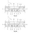
- FIGS. 2a and 2b show the fitting device FIG. 1 in a top view from below.
- the setting of the stop 10 in the in the FIG. 2a shown fitting device 1 is used in comparison to the setting of the stop 10 in the in the FIG. 2b illustrated fitting device 1 to adjust a glass door with a lower glass thickness to the door system and in particular to the glass thickness of the clamped in the fitting door element 2 to compensate for the angular offset.
- To adjust the stop 10 via the adjusting element 6, namely to compensate for the angular offset between the door element 2 and the glass door is in FIG.
- the adjusting element 6 is shifted to the glass center AA of the door element 2 and is fixed in this position, namely towards the glass center AA, via the fastening elements 9 which engage as threaded pins through the recesses 8 designed as threaded bores.
- the stopper 10 is displaced outwards from the center of the glass AA, namely as shown here FIG. 2b shown shifted down. In this position, the adjusting element 6 and arranged on the adjusting element 6 stop 10 is fixed on the fitting element 3 designed as threaded fasteners.
- the adjusting element 6 is designed as a holding element 13 which is parallel to the fitting elements 3 and 4 of the fitting device 1 and between the fitting elements 3 and 4, namely orthogonal to the surface of the clamped between the fitting elements 3 and 4 door element 2 is movable or displaced.
- the adjusting element 6 is operatively connected via pins 14 with a connecting element 15.
- the connecting element 15 in this case has a recess 16, in which an edge of the 7.1 designed as an angle 6.2 stop 10th positively engages. In the edge of the 7.1 designed as an angle 6.2 stop 10, a recess 8 is designed in the form of a slot.
- the connecting element 15 may also be formed integrally, ie integrally with the stop 10 designed as an angle piece 6.2.
- the connecting element 15 offers in a two-part design of elbow 6.2 and connecting element 15 of the advantage that both via the holding element 13, which serves here as a first adjusting element 6, an adjustment of the stop 10 takes place.
- a second adjusting 6 configured with an even larger adjustment range can be formed by the relative displacement between the designed as an angle 6.2 stop 10 and the connecting element 15 .
- an even greater angular offset between two door elements ie an even greater difference between the glass thicknesses of two door elements, can be compensated for in addition via the stop 10 designed as an angle piece 6.2 with a recess 8 formed in the edge 7.1.
- FIGS. 4a and 4b Show is also in the FIG. 3 illustrated fitting device 1, here in particular the stop 10 via the adjusting element 6, namely here on the integrally formed with the stop 10 adjustment 6 by means of configured as a slot recess 8 relative to the glass center AA of the door element 2 between the fitting elements 3 and 4 slidably.
- the stop 10 with the sheet-like element 11 via the slot configured recess 8 is displaced to the stop on the head of the fastener 9 configured as a screw in the direction of the glass center point AA of the door element 2.
- FIG. 4a illustrated setting of the stop 10, which is set to a glass door with a low glass thickness, as in FIG. 4b shown, the stop 10, in particular the arranged on the stop 10 stopper 12 is shifted from the glass center AA down, wherein the configured as a screw fastener 9 is approximately in the middle of the elongated hole configured recess 8.
- the stopper 10 can also be made via the configured as a holding element 13 adjustment 6, namely by its displacement between the fitting elements 3 and 4 of the fitting device 1 adjustment of the stop 10.
- the configured as an angle 6.2 adjusting element 6, which is configured integrally with the stop 10 in addition to the designed as a holding element 13 adjustment 6 of the adjustment of the stop can be further expanded, ie in particular a displacement of the stopper 10 and in particular of the stopper 12th away from the glass center AA and thus the distance between the stopper 12 and the glass center AA are still increased.
- the stop 10 can be moved parallel to the fitting elements 3 and 4
- the door element 2 clamped between the fitting elements 3 and 4 of the fitting device 1 a designed as a skylight upper part and / or a side part of a glass door system, wherein between the upper part and the side part or the side panels a glass door is connected.
Abstract
Die Erfindung betrifft eine Beschlagvorrichtung (1) für ein Türelement (2), insbesondere für ein Türelement (2) einer Glastüranlage, umfassend ein erstes Beschlagelement (3) und ein zweites Beschlagelement (4), welche einen Einspannbereich (5) für das Türelement (2) bildend unter Einspannen des Türelements (2) miteinander verbindbar sind, und wobei zwischen den Beschlagelementen (3, 4) ein relativ zu den Beschlagelementen (3, 4) und zu dem in dem Einspannbereich (5) aufgenommenen Türelement (2) verschiebbares Einstellelement (6) angeordnet ist, das mit wenigstens einem der Beschlagelemente (3, 4) kraft- und/oder formschlüssig koppelbar ist. Erfindungsgemäß ist vorgesehen, dass an dem Einstellelement (6) ein Anschlag (10) angeordnet ist.The invention relates to a fitting device (1) for a door element (2), in particular for a door element (2) of a glass door system, comprising a first fitting element (3) and a second fitting element (4) which has a clamping region (5) for the door element (5). 2) forming under clamping of the door element (2) are connectable to each other, and wherein between the fitting elements (3, 4) relative to the fitting elements (3, 4) and to the in the clamping area (5) received door element (2) displaceable adjusting element (6) is arranged, which is non-positively and / or positively coupled with at least one of the fitting elements (3, 4). According to the invention, it is provided that a stop (10) is arranged on the adjusting element (6).
Description
Die vorliegende Erfindung betrifft eine Beschlagvorrichtung für ein Türelement, insbesondere für ein Türelement einer Glastüranlage, nach dem Oberbegriff von Anspruch 1, umfassend ein erstes Beschlagelement und ein zweites Beschlagelement, welche einen Einspannbereich für das Türelement bildend unter Einspannen des Türelementes miteinander verbindbar sind, und wobei zwischen den Beschlagelementen ein relativ zu den Beschlagelementen und zu dem in dem Einspannbereich aufgenommenen Türelement verschiebbares Einstellelement angeordnet ist, das mit wenigstens einem der Beschlagelemente kraft- und/oder formschlüssig koppelbar ist.The present invention relates to a fitting device for a door element, in particular for a door element of a glass door system, according to the preamble of
Derartige Beschlagvorrichtungen werden sowohl an Türen, als auch an Fenstern montiert und sollen innerhalb eines Beschlagsystems ein optisch vorteilhaftes Erscheinungsbild aufweisen. Die Beschlagvorrichtungen bestehen zumeist aus zwei Beschlagelementen, zwischen die das Türelement, beispielsweise Seiten- und/oder Oberteile einer Glastüranlage geklemmt werden. Neben der Klemmung werden die Türelemente von den Beschlagvorrichtungen entsprechend vorgegebener Standards auch von Befestigungselementen gehalten, die durch die Beschlagvorrichtungen durch Ausnehmungen, beispielsweise in Gestalt von Bohrungen und durch Ausnehmungen in dem Türelement geführt sind. Um die Türelemente zwischen den Beschlagelementen zu klemmen, sind die Eckbereiche der Türelemente entlang deren Kontur ausgeschnitten. An der Kontur können so die Beschlagelemente zur Anlage gelangen, und bilden über den Ausschnitt des Türelementes einen Freiraum, der beispielsweise dazu dient, um über ein Verbindungselement, das Bestandteil der Beschlagvorrichtung ist, und das vorzugsweise zwischen den Beschlagelementen angeordnet ist, ein als Schwenk- und/oder Pendeltür ausgestaltetes Türelement auf einen Drehpunkt und/oder einer Achse anordenbar bzw. montierbar ist. Insbesondere dienen die bekannten Beschlagvorrichtungen dazu, um Glastüren bzw. Glastürelemente in einer Ganzglastüranlage einzubauen, bei der die Oberteile, als auch die Seitenteile aus Glas bestehen. Dabei werden zumeist für die Seiten- bzw. Oberteile der Glastüranlage dickere Gläser als für das daran angebundene Glastürelement verwendet. Auf Grund der unterschiedlichen Glasstärken zwischen Glastür und den Seiten- bzw. Oberteilen, d. h. zwischen den Türelementen der Glastüranlage kommt es insbesondere beim Anschlag der Tür, d. h. im Bereich der oberen Ecke der Tür, die diagonal gegenüberliegend dem Drehpunkt der Tür liegt, auf Grund des definierten Abstandes der bekannten Anschläge zu einem Ebenen- oder Winkelversatz zwischen den Glasflächen der Glastür und den Glasflächen der Seiten- bzw. Oberteile der Türanlage. Um den Ebenenversatz ausgleichen zu können ist es bekannt, die bekannten Anschläge mittels Unterlegscheiben zu verschieben. Da jedoch die Unterlegscheiben nicht in jeder Stärke verfügbar sind, kann eine flexible Einstellung der Anschläge an den bekannten Beschlagvorrichtungen nicht vorgenommen werden.Such fitting devices are mounted both on doors, and on windows and should have a visually advantageous appearance within a fitting system. The fitting devices usually consist of two fitting elements, between which the door element, for example side and / or upper parts of a glass door system are clamped. In addition to the clamping, the door elements are held by the fitting devices according to predetermined standards and fasteners that are guided by the fitting devices through recesses, for example in the form of holes and recesses in the door element. In order to clamp the door elements between the fitting elements, the corner regions of the door elements are cut along the contour thereof. On the contour so the fitting elements can come to rest, and form over the cutout of the door element a free space, which serves, for example, to over a Connecting element, which is part of the fitting device, and which is preferably arranged between the fitting elements, designed as a pivoting and / or swing door element on a pivot point and / or an axis can be arranged or mounted. In particular, the known fitting devices are used to install glass doors or glass door elements in a glass door system in which the tops, as well as the side panels made of glass. In this case, thicker glasses are usually used for the side or upper parts of the glass door system than for the glass door element connected thereto. Due to the different glass thicknesses between the glass door and the side or upper parts, ie between the door elements of the glass door system it comes in particular at the stop of the door, ie in the upper corner of the door, which is diagonally opposite the pivot point of the door, due to defined distance of the known attacks to a plane or angular offset between the glass surfaces of the glass door and the glass surfaces of the side or upper parts of the door system. In order to compensate for the plane offset, it is known to move the known stops by means of washers. However, since the washers are not available in any thickness, flexible adjustment of the stops on the known fitting devices can not be made.
Es ist daher die Aufgabe der vorliegenden Erfindung, die voranstehend beschriebenen Nachteile des Standes der Technik zu beheben. Insbesondere ist es die Aufgabe der vorliegenden Erfindung eine Beschlagvorrichtung zur Verfügung zu stellen, die eine stufenlose Festlegung eines Anschlages an der Beschlagvorrichtung ermöglicht und mit der der Ebenenversatz zwischen den Türelementen einer Glastüranlage einstellbar ist.It is therefore the object of the present invention to overcome the above-described disadvantages of the prior art. In particular, it is the object of the present invention to provide a fitting device which enables stepless fixing of a stop to the fitting device and with which the plane offset between the door elements of a glass door system can be adjusted.
Die voranstehende Aufgabe wird durch eine Beschlagvorrichtung mit den Merkmalen des Anspruches 1 gelöst. Weitere Vorteile, Merkmale und Details der Erfindung ergeben sich aus den Unteransprüchen, der Beschreibung und den Zeichnungen.The above object is achieved by a fitting device with the features of
Die Erfindungsgemäße Beschlagvorrichtung für ein Türelement, insbesondere für ein Türelement einer Glastüranlage, schließt die technische Lehre ein, dass an dem Einstellelement ein Anschlag angeordnet ist.The inventive fitting device for a door element, in particular for a door element of a glass door system, includes the technical teaching that a stop is arranged on the adjusting element.
Diese Lösung bietet den Vorteil, dass über das zwischen den Beschlagelementen und zu dem in dem Einspannbereich aufgenommenen Türelement verschiebbare Einstellelement auch der an dem Einstellelement angeordnete Anschlag relativ zu den Beschlagelementen und zu dem in dem Einspannbereich aufgenommenen Türelement verschiebbar bzw. für eine Feinjustierung innerhalb der Beschlagvorrichtung verlagerbar ist. Entsprechend lässt sich der Anschlag mit dem Einstellelement sowohl zumindest abschnittsweise in paralleler Richtung zur Längserstreckung der Beschlagelemente, d. h. parallel zu den Flächen des in dem Einspannbereich zwischen den Beschlagelementen eingespannten Glastürelementes verschieben. Zum anderen kann der Anschlag zum Glasmittelpunkt hin oder nach außen, d. h. orthogonal zu den Glasflächen verschoben werden, um den Anschlag an dem Türelement je nach Gegebenheit ausrichten zu können. Durch die Anordnung des Anschlages an dem Einstellelement kann der Anschlag mit dem Einstellelement so verschoben bzw. eingestellt werden, dass zumindest eine Fläche des Glastürelementes mit zumindest einer Fläche der Seitenteile bzw. des Oberteils der Türanlage auf einer Ebene ohne Versatz liegen.This solution has the advantage that displaceable via the arranged between the fitting elements and to the recorded in the clamping area door element adjustment also arranged on the adjusting stop relative to the fitting elements and to the recorded in the Einspannbereich door element or for a fine adjustment within the fitting device is relocatable. Accordingly, the stop with the adjusting element can both at least partially in the direction parallel to the longitudinal extension of the fitting elements, ie move parallel to the surfaces of the clamped in the clamping between the fitting elements glass door element. On the other hand, the stop can be moved towards the center of the glass or outwards, ie orthogonally to the glass surfaces in order to align the stop on the door element depending on the circumstances. Due to the arrangement of the stop on the adjusting element, the stop can be displaced or adjusted with the adjusting element so that at least one surface of the glass door element with at least one surface of the side parts or the upper part of the door system lie on a plane without offset.
In vorteilhafter Weise ist das Einstellelement integral mit dem Anschlag ausgestaltet. Als integrale Ausgestaltung soll dabei sowohl eine einstückige Ausgestaltung des Einstellelementes mit dem Anschlag verstanden werden, als auch eine Bau- bzw. Montagegruppe oder - einheit, die aus dem Einstellelement und dem Anschlag besteht. Bei der integralen Ausgestaltung des Einstellelementes mit dem Anschlag kann das Einstellelement im Sinne der vorliegenden Erfindung auch als der Anschlag verstanden werden. Ist der Anschlag als Einstellelement ausgestaltet, kann dieser direkt an wenigstens einem der Beschlagelemente kraft- und/oder formschlüssig koppelbar sein, oder der als Einstellelement ausgestaltete Anschlag kann über ein zusätzliches Einstellelement oder an einem mit diesem Einstellelement wirkverbundenen Verbindungselement an wenigstens einem der Beschlagelemente kraft- und/oder formschlüssig koppelbar sein.Advantageously, the adjusting element is designed integrally with the stop. An integral embodiment is to be understood both an integral configuration of the adjustment with the stop, as well as a construction or assembly group or - unit, which consists of the adjustment and the stop. In the integral embodiment of the adjusting element with the stop, the adjustment can be understood in the context of the present invention as the stop. If the stop is configured as an adjusting element, it can be positively and / or positively coupled directly to at least one of the fitting elements, or the stop configured as an adjusting element can be connected to at least one of the fitting elements via an additional adjusting element or on a connecting element operatively connected to this adjusting element. and / or be positively coupled.
Der Anschlag kann vorteilhaft zumindest formschlüssig mit dem Einstellelement koppelbar sein. Natürlich kann optional, oder auch in Kombination mit der formschlüssigen Kopplung zwischen dem Anschlag und dem Einstellelement, der Anschlag auch kraftschlüssig mit dem Einstellelement koppelbar sein. Zur kraftschlüssigen Kopplung zwischen dem Einstellelement und dem Anschlag können z. B. Befestigungselemente in Form von Schrauben, Nieten oder dazu äquivalente Befestigungselemente dienen.The stop can advantageously be coupled to the adjustment element at least in a form-fitting manner. Of course, optionally, or in combination with the positive coupling between the stop and the adjusting element, the stopper can also be positively coupled to the adjusting element. For frictional coupling between the adjustment and the stop z. B. fasteners in the form of screws, rivets or equivalent fasteners serve.
In besonders vorteilhafter Weise ist der Anschlag relativ zu dem Einstellelement verschiebbar. Durch die relative Verschiebbarkeit zwischen dem Einstellelement und dem Anschlag kann insbesondere die Lage des Anschlages in der Beschlagvorrichtung nochmals verändert bzw. eingestellt werden. Ist beispielsweise die Differenz der Glasstärke zwischen den Seiten- bzw. Oberteilen der Türanlage zu dem Türelement besonders groß, lässt sich der Ebenen- bzw. Winkelversatz zwischen dem Türelement und der Glastüranlage im Bereich des Anschlages sowohl über das zwischen den Beschlagelementen und dem relativ zu dem Türelement verschiebbare Einstellelement und ergänzend durch den an dem Einstellelement verschiebbaren als zusätzliches Einstellelement ausgestalteten Anschlag einstellen. Entsprechend kann mit der erfindungsgemäßen Beschlagvorrichtung, nämlich hier insbesondere mit dem relativ zu dem Einstellelement verschiebbaren Anschlag der Einstellbereich noch erweitert werden.In a particularly advantageous manner, the stop is displaceable relative to the adjusting element. In particular, the position of the stop in the fitting device can be changed or adjusted again by the relative displaceability between the adjustment and the stop. For example, is the difference in the glass thickness between the side and top parts of the door system to the door element particularly large, the level or angular offset between the door element and the glass door system in the region of the stop can be adjusted both via the adjustable between the fitting elements and relative to the door element adjustment and complementally displaceable by the adjusting element as an additional adjustment stop. Accordingly, with the fitting device according to the invention, namely here in particular with the displaceable relative to the adjustment stop the adjustment range can be further expanded.
Vorteilhaft kann das Einstellelement als Halteelement ausgestaltet, dass in Wirkverbindung mit einem Verbindungselement steht, mit dem der Anschlag kraft- und/oder formschlüssig koppelbar ist. Zur Ausrichtung der Türelemente, d. h. zum Ausgleich eines Winkelversatzes zwischen einer Glastür und den Seitenteilen und/oder dem Oberteil einer Türanlage kann in vorteilhafterweise ein als T-Stück ausgestaltetes Halteelement dienen. Das Halteelement weist bevorzugt Flächen auf, die in Ausnehmungen der Beschlagelemente geführt werden, und an denen Auflageabschnitte ausgestaltet sind, die eine ausreichend große Auflage bieten, um das mit dem Halteelement wirkverbundene Verbindungselement und den daran angeordneten Anschlag in einem Toleranzbereich von ca. 10 mm bis 20 mm von bzw. zu dem Glasmittelpunkt des zwischen den Beschlagelementen eingespannten Glastürelementes zu bewegen.Advantageously, the adjusting element designed as a holding element that is in operative connection with a connecting element, with which the stop non-positively and / or positively coupled. For aligning the door elements, d. H. to compensate for an angular offset between a glass door and the side panels and / or the upper part of a door system can advantageously serve as a T-piece ausgestaltetes retaining element. The holding element preferably has surfaces which are guided in recesses of the fitting elements, and on which support sections are designed which provide a sufficiently large support to the operatively connected to the holding element connecting element and the abutment arranged thereon in a tolerance range of about 10 mm 20 mm from or to the glass center of the clamped between the fitting elements glass door element to move.
Ist das Einstellelement wie beschrieben als Halteelement ausgestaltet, weist das Halteelement vorzugsweise eine T-förmige Bauart auf, mit zwei orthogonal zueinander stehenden Flächen. Dabei wird das als Halteelement ausgestaltete Einstellelement über eine der Flächen bevorzugt beidseitig in beiden Beschlagelementen, beispielsweise in der in den Beschlagelementen als Nut ausgestalteten Ausnehmung bzw. Führung geführt, und gelangt in besonders bevorzugter Weise an beiden Beschlagelementen zur kraft- und/oder formschlüssigen Anlage. Das als T-förmiges Halteelement ausgestaltete Einstellelement hat den weiteren Vorteil, dass dieses nicht nur parallel in Längsrichtung zu den Beschlagelementen in der Führung der Beschlagelemente verschiebbar bzw. führbar ist, sondern auch in dem genannten Toleranzbereich zwischen den Beschlagelementen, d. h. zum einen oder zum anderen Beschlagelement hin verschiebbar bzw. verlagerbar ist. Dadurch kann über das als Halteelement ausgestaltete Einstellelement nicht nur ein Ebenen- bzw. Winkelversatz zwischen den Seitenteilen bzw. dem Oberteil einer Türanlage und der Glastür eingestellt werden, sondern der Anschlag kann zudem parallel zu den Beschlagelementen verschoben werden, wodurch der Anschlagbereich für die Glastür zusätzlich eingestellt werden kann.If the adjusting element is designed as a holding element as described, the holding element preferably has a T-shaped design, with two surfaces which are orthogonal to one another. In this case, the adjusting element designed as a holding element is preferably provided on both sides in both fitting elements via one of the surfaces, for example in the recess designed as a groove in the fitting elements or Guide out, and arrives in a particularly preferred manner to both hardware elements for non-positive and / or positive fit plant. The adjusting element configured as a T-shaped retaining element has the further advantage that it can not only be displaced or guided parallel in the longitudinal direction to the fitting elements in the guide of the fitting elements, but also in the aforementioned tolerance range between the fitting elements, ie on the one hand or on the other Fitting element is displaced or displaced. As a result, not only a level or angular offset between the side panels or the upper part of a door system and the glass door can be adjusted via the designed as a holding element adjustment, but the stop can also be moved parallel to the fitting elements, whereby the stop area for the glass door in addition can be adjusted.
In vorteilhafterweise ist der Anschlag über ein Verbindungselement, welches mit dem als Halteelement ausgestalteten Einstellelement wirkverbunden ist, mit dem Einstellelement kraft- und/oder formschlüssig koppelbar. Zur formschlüssigen Kopplung bzw. zur formschlüssigen Aufnahme des Anschlages in oder an dem Verbindungselement, ist das Verbindungselement in vorteilhafterweise derart ausgestaltet, dass durch zumindest abschnittsweises Einführen des Anschlages in das Verbindungselement, d. h. hier bevorzugt in eine an dem Verbindungselement ausgestalteten Aussparung der Anschlag formschlüssig greift. Zur formschlüssigen Kopplung zwischen dem Verbindungselement und dem Anschlag, kann die Kopplung in vorteilhafter Weise als Schwalbenschwanzkopplung ausgestaltet sein.Advantageously, the stop via a connecting element, which is operatively connected to the adjusting element designed as a holding element, with the adjusting force and / or positively coupled. For positive coupling or for positive reception of the stop in or on the connecting element, the connecting element is advantageously designed such that by at least partially insertion of the stop in the connecting element, d. H. Here preferably engages positively in a recess formed on the connecting element recess of the stop. For the positive coupling between the connecting element and the stop, the coupling can be configured advantageously as a dovetail coupling.
Zusätzlich zu der formschlüssigen Kopplung zwischen dem Verbindungselement und dem Anschlag, bzw. der formschlüssigen Kopplung zwischen dem Anschlag und dem Einstellelement kann der Anschlag in vorteilhafterweise zusätzlich kraftschlüssig mit dem Verbindungselement gekoppelt sein. Zur kraftschlüssigen Kopplung zwischen dem Anschlag und dem Verbindungselement dient bevorzugt wenigstens ein Befestigungselement, welches beispielsweise in Form einer Schraube ausgestaltet sein kann.In addition to the positive coupling between the connecting element and the stop, or the positive Coupling between the stop and the adjusting element, the stop can be coupled in an advantageously additional non-positively with the connecting element. For non-positive coupling between the stop and the connecting element is preferably at least one fastener, which may be configured, for example in the form of a screw.
Vorteilhafterweise ist an dem Anschlag zumindest eine Ausnehmung in Form einer Bohrung oder einer Fräsung ausgestaltet, in der das Befestigungselement, welches beispielsweise ein Außengewinde aufweist, kraft- und/oder formschlüssig greift, bzw. durch die Ausnehmung hindurchgreift und in einer an dem Verbindungselement oder dem Einstellelement ausgestalteten Bohrung mit Innengewinde, welches dem Außengewinde des Befestigungselementes angepasst ist, kraft- und formschlüssig greift.Advantageously, at least one recess in the form of a bore or a milling configured in the fastening element, which has, for example, an external thread, non-positively and / or positively engages, or passes through the recess and engages in a on the connecting element or the Adjusting element configured bore with internal thread, which is adapted to the external thread of the fastener, engages positively and positively.
Besonders bevorzugt ist das Einstellelement als Winkelelement oder Winkelstück ausgestaltet. Bei integraler Ausgestaltung des Einstellelementes mit dem Anschlag ist der Anschlag als Winkelelement oder Winkelstück ausgestaltet. Im einfachsten Fall weist das Winkelelement oder Winkelstück zwei orthogonal zueinander stehende Flanken auf, wobei die eine Flanke zur Anordnung des Anschlages, und hier insbesondere zur Anordnung eines Stoppers, und die andere Flanke zur kraft- und/oder formschlüssigen Kopplung mit dem Verbindungselement bzw. mit dem Beschlagelement dient. Dazu ist an der Flanke, die zur kraft- und/oder formschlüssigen Kopplung mit dem Verbindungselement oder dem Beschlagelement dient, die Ausnehmung in Form einer Bohrung oder einer Fräsung ausgestaltet, durch die das Befestigungselement greift bzw. an der das Befestigungselement kraft- und formschlüssig koppelbar ist.Particularly preferably, the adjustment is configured as an angle or elbow. In an integral embodiment of the adjustment with the stop the stop is designed as an angle or elbow. In the simplest case, the angle element or elbow on two mutually orthogonal flanks, wherein one flank to the arrangement of the stop, and in particular for the arrangement of a stopper, and the other edge for non-positive and / or positive coupling with the connecting element or with the fitting element is used. For this purpose, the recess in the form of a bore or a milling configured on the edge, which serves for non-positive and / or positive coupling with the connecting element or the fitting element through which engages the fastener or on which the fastener positively and positively coupled is.
In besonders vorteilhafterweise weist das Einstellelement, das als Winkelelement ausgestaltet ist, und welches mit zumindest einem der Beschlagelemente kraft- und/oder formschlüssig koppelbar ist, ein U-förmiges Profil auf. Das U-förmige Winkelelement gelangt in bevorzugter Weise zumindest abschnittsweise an einem der Beschlagelemente der Beschlagvorrichtung zum Eingriff. Dabei ist das U-förmige Winkelelement über die parallel zueinander liegenden Flanken sowohl parallel zu den Beschlagelementen der Beschlagvorrichtung als zwischen den Beschlagelementen zumindest abschnittweise hin und her verschiebbar, nämlich bis zum Anliegen der zwischen den parallel liegenden Flanken orthogonal angeordneten Flanke an eines der Beschlagelemente. Somit ist über das als U-förmiges Winkelelement ausgestaltete Einstellelement eine Verschiebung, d. h. eine Einstellung des Anschlages zum Glasmittelpunkt hin oder nach außen vom Glasmittelpunkt weg, durchführbar.In a particularly advantageous manner, the adjusting element, which is designed as an angle element, and which is non-positively and / or positively coupled with at least one of the fitting elements, a U-shaped profile. The U-shaped angle element passes in a preferred manner at least partially on one of the fitting elements of the fitting device for engagement. In this case, the U-shaped angle element on the mutually parallel flanks both parallel to the fitting elements of the fitting device as between the fitting elements at least partially displaced back and forth, namely to the concern of between the flanks lying parallel flank perpendicular to one of the fitting elements. Thus, over the designed as a U-shaped angle element adjustment is a shift, d. H. a setting of the stop to the glass center point out or away from the glass center away, feasible.
Zur Fixierung des Einstellelementes, d. h. auch zur Fixierung des integral mit dem Einstellelement ausgestalteten Anschlages bzw. des mit dem Einstellelement kraft- und/oder formschlüssig gekoppelten Anschlages ist zumindest an einer der parallelen Flanken des als U-Profil ausgestalteten Winkelelementes eine Gewindebohrung, und besonders bevorzugt zwei Gewindebohrungen ausgestaltet, in die als Befestigungselemente ausgestaltete Gewindestifte greifen, die sich beim Eindrehen in die Gewindebohrungen mit ihrem freien Ende gegen die Außenwand der Beschlagelemente drücken und somit das Einstellelement und damit auch den Anschlag an der Beschlagvorrichtung, und insbesondere an zumindest einem der Beschlagelemente fixieren. Da hier die Fixierung des Einstellelementes durch Festdrehen, d. h. durch den Anpressdruck der durch die Gewindebohrungen eingedrehten Gewindestifte erfolgt, ist eine stufenlose Einstellbarkeit, bzw. eine Feinjustierung des Anschlages im Anschlagsbereich mit der erfindungsgemäßen Beschlagvorrichtung durchführbar.For fixing the adjusting element, ie also for fixing the integral with the adjusting stop or the force-locked with the adjusting and / or positively locking stop is at least on one of the parallel edges of the U-profile designed as a threaded element, and particularly preferred designed two threaded holes, engage in the designed as fasteners threaded pins that press when screwing into the threaded holes with its free end against the outer wall of the fitting elements and thus fix the adjustment and thus the stop on the fitting, and in particular on at least one of the fitting elements , Since here the fixation of the adjusting element by tightening, ie by the contact pressure of the threaded holes screwed through the threaded holes, is a stepless adjustability, or a fine adjustment of the stop in the attack area with the fitting device according to the invention carried out.
Zur Erweiterung des Einstellbereiches weist der Anschlag bzw. das integral mit dem Anschlag ausgestaltete Einstellelement, welches als Winkelstück mit zwei orthogonal zueinander liegenden Flanken ausgestaltet ist, bevorzugt eine Ausnehmung in Form eines Langloches auf. Dabei greift das Befestigungselement, welches zur kraftschlüssigen Kopplung zwischen dem Anschlag bzw. dem als Einstellelement ausgestalteten Anschlag und dem Verbindungselement dient, bevorzugt in eine an dem Verbindungselement ausgestaltete Bohrung mit Innengewinde, die dem Außengewinde des Befestigungselementes angepasst ist.In order to widen the adjustment range, the stop or the adjustment element designed integrally with the stop, which is designed as an angle piece with two mutually orthogonal flanks, preferably has a recess in the form of an oblong hole. In this case, the fastening element, which serves for non-positive coupling between the stop or the stop configured as an adjustment element and the connecting element, preferably engages in a formed on the connecting element bore with internal thread, which is adapted to the external thread of the fastening element.
Weitere, die Erfindung verbessernde Maßnahmen werden nachstehend gemeinsam mit der Beschreibung von bevorzugten Ausführungsbeispielen der Erfindung anhand der Figuren näher dargestellt. Dabei können die in den Ansprüchen und in der Beschreibung erwähnten Merkmale jeweils einzeln für sich oder in beliebiger Kombination erfindungswesentlich sein.
Es zeigen:
- Fig. 1
- einen Ausschnitt einer ersten Ausführungsform einer erfindungsgemäßen Beschlagvorrichtung mit einem daran angeordneten Anschlag in einer perspektivischen Detailansicht,
- Fig. 2a, b
- die Beschlagvorrichtung aus
Figur 1Figur 4b , - Fig. 3
- einen Ausschnitt einer zweiten Ausführungsform einer erfindungsgemäßen Beschlagvorrichtung in einer perspektivischen Detailansicht und
- Fig. 4a, b
- den Ausschnitt der Beschlagvorrichtung aus
Figur 3 in einer Draufsicht von unten mit Einstellung des Anschlages auf eine dünne Glastür 4a und auf eine dicke GlastürFigur 4b .
Show it:
- Fig. 1
- a detail of a first embodiment of a fitting device according to the invention with a stop arranged thereon in a perspective detail view,
- Fig. 2a, b
- the fitting device
FIG. 1 in a plan view from below with adjustment of the stop on a thin glass door 4a and on a thick glass doorFIG. 4b . - Fig. 3
- a detail of a second embodiment of a fitting device according to the invention in a perspective detail view and
- Fig. 4a, b
- the cutout of the fitting device
FIG. 3 in a plan view from below with adjustment of the stop on a thin glass door 4a and on a thick glass doorFIG. 4b ,
In den unterschiedlichen Figuren sind gleiche Teile stets mit denselben Bezugszeichen versehen, weshalb diese in der Regel auch nur einmal beschrieben werden.In the different figures, the same parts are always provided with the same reference numerals, which is why they are usually described only once.
Die
Wie die
Zur Anbindung einer Glastür mit einer dickeren Glasstärke an ein Türelement 2 wird gegenüber der in der
Zusätzlich zu der Einstellmöglichkeit des Anschlages 10 über das integral mit dem Anschlag 10 ausgestaltete Einstellelement 6, wie in den
Vorliegend handelt es sich bei den, zwischen den Beschlagelementen 3 und 4 der Beschlagvorrichtung 1 eingespannten Türelement 2 bevorzugt um ein als Oberlicht ausgestaltetes Oberteil und/oder um ein Seitenteil einer Glastüranlage, wobei zwischen dem Oberteil und dem Seitenteil bzw. den Seitenteilen eine Glastür angebunden ist.In the present case, it is preferable for the
- 11
- Beschlagvorrichtungfitting device
- 22
- Türelementdoor element
- 33
- Beschlagelementfitting element
- 44
- Beschlagelementfitting element
- 55
- Einspannbereichclamping
- 66
- Einstellelementadjustment
- 6.16.1
- Einstellelement als WinkelelementSetting element as an angle element
- 6.26.2
- Einstellelement als WinkelstückSetting element as an angle piece
- 77
- Flanke zu 6, 6.1Edge to 6, 6.1
- 7.17.1
- Flanke zu 6, 6.2Edge to 6, 6.2
- 88th
- Ausnehmungrecess
- 99
- Befestigungselementfastener
- 1010
- Anschlagattack
- 1111
- flächiges Elementflat element
- 1212
- Stopperstopper
- 1313
- Halteelementretaining element
- 1414
- Zapfen zu 13Tenons to 13
- 1515
- Verbindungselementconnecting element
- 1616
- Aussparung zu 15Recess to 15
- AAAA
- Glasmittelpunkt zu 2Glass center to 2
Claims (11)
dadurch gekennzeichnet,
dass an dem Einstellelement (6) ein Anschlag (10) angeordnet ist.Fitting device (1) for a door element (2), in particular for a door element (2) of a glass door system, comprising a first fitting element (3) and a second fitting element (4) forming a clamping region (5) for the door element (2) Clamping of the door element (2) are connectable to each other, and wherein between the fitting elements (3, 4) arranged relative to the fitting elements (3, 4) and to the in the clamping area (5) door element (2) displaceable adjusting element (6) is that with at least one of the fitting elements (3, 4) non-positively and / or positively coupled,
characterized,
in that a stop (10) is arranged on the adjusting element (6).
dadurch gekennzeichnet,
dass das Einstellelement (6) integral mit dem Anschlag (10) ausgestaltet ist.Fitting device (1) according to claim 1,
characterized,
in that the adjusting element (6) is designed integrally with the stop (10).
dadurch gekennzeichnet,
dass der Anschlag (10) kraft- und/oder formschlüssig mit dem Einstellelement (6) koppelbar ist.Fitting device (1) according to claim 1,
characterized,
that the stop (10) positively and / or positively to the adjusting element (6) can be coupled.
dadurch gekennzeichnet,
dass der Anschlag (10) relativ zu dem Einstellelement (6) verschiebbar ist.Fitting device (1) according to claim 1 or 3,
characterized,
that the stop (10) relative to the adjusting element (6) is displaceable.
dadurch gekennzeichnet,
dass das Einstellelement (6) als Halteelement (13) ausgestaltet ist, das in Wirkverbindung mit einem Verbindungselement (15) steht, das mit dem Anschlag (10) kraft- und/oder formschlüssig koppelbar ist, oder das integral mit dem Anschlag (10) ausgestaltet ist.Fitting device (1) according to one of the preceding claims,
characterized,
in that the adjusting element (6) is designed as a retaining element (13) which is in operative connection with a connecting element (15) which can be positively and / or positively coupled to the stop (10) or which is integral with the stop (10). is designed.
dadurch gekennzeichnet,
dass das Halteelement (13) T-förmig mit zwei orthogonal zueinander stehenden Flächen ausgestaltet ist, wobei eine der Flächen beidseitig der anderen Fläche ausgestaltet ist.Fitting device (1) according to claim 5,
characterized,
in that the holding element (13) is configured in a T-shape with two surfaces which are orthogonal to one another, one of the surfaces being configured on both sides of the other surface.
dadurch gekennzeichnet, dass der Anschlag (10) an dem Verbindungselement (15) führbar gelagert ist.Fitting device (1) according to claim 5 or 6,
characterized in that the stop (10) is guidably mounted on the connecting element (15).
dadurch gekennzeichnet,
dass das Einstellelement (6) als Winkelelement (6.1) oder Winkelstück (6.2) ausgestaltet ist.Fitting device (1) according to one of the preceding claims,
characterized,
that the adjusting element (6) is designed as angle element (6.1), or angle piece (6.2) configured.
dadurch gekennzeichnet,
dass das Winkelelement (6.1) ein im Wesentlichen U-förmiges Profil aufweist.Fitting device (1) according to claim 8,
characterized,
that the angle element (6.1) has a substantially U-shaped profile.
dadurch gekennzeichnet,
dass das Einstellelement (6, 6.1, 6.2) an wenigstens einer Flanke (7, 7.1) zumindest eine Ausnehmung (8) zum Durchführen eines Befestigungselements (9) aufweist.Fitting device (1) according to claim 8 or 9,
characterized,
that the adjusting element (6, 6.1, 6.2) at at least one edge (7, 7.1) comprises at least one recess (8) for performing a fastening element (9).
dadurch gekennzeichnet,
dass die Ausnehmung (8) als Langloch und/oder als Gewindebohrung ausgestaltet ist.Fitting device (1) according to claim 10,
characterized,
that the recess (8) is designed as a slot and / or a threaded hole.
Priority Applications (2)
| Application Number | Priority Date | Filing Date | Title |
|---|---|---|---|
| EP14196283.7A EP3029254A1 (en) | 2014-12-04 | 2014-12-04 | Variable stop |
| CN201510323894.2A CN105672813B (en) | 2014-12-04 | 2015-06-12 | Variable stop |
Applications Claiming Priority (1)
| Application Number | Priority Date | Filing Date | Title |
|---|---|---|---|
| EP14196283.7A EP3029254A1 (en) | 2014-12-04 | 2014-12-04 | Variable stop |
Publications (1)
| Publication Number | Publication Date |
|---|---|
| EP3029254A1 true EP3029254A1 (en) | 2016-06-08 |
Family
ID=52102480
Family Applications (1)
| Application Number | Title | Priority Date | Filing Date |
|---|---|---|---|
| EP14196283.7A Withdrawn EP3029254A1 (en) | 2014-12-04 | 2014-12-04 | Variable stop |
Country Status (2)
| Country | Link |
|---|---|
| EP (1) | EP3029254A1 (en) |
| CN (1) | CN105672813B (en) |
Citations (4)
| Publication number | Priority date | Publication date | Assignee | Title |
|---|---|---|---|---|
| EP0035143A2 (en) * | 1980-03-04 | 1981-09-09 | VEGLA Vereinigte Glaswerke GmbH | Hinge fitting for all-glass doors |
| DE8536840U1 (en) * | 1985-10-25 | 1990-02-08 | Societa Italiana Progetti S.R.L., Magenta, Mailand/Milano, It | |
| EP0362044A1 (en) * | 1988-09-27 | 1990-04-04 | O. MUSTAD & FILS - S.A. | Polyvalent fixing device for glass assemblies, such as fan lights, frames and doors, comrpising a reversible and modular unit |
| DE102009022802A1 (en) * | 2009-05-27 | 2010-12-02 | Dorma Gmbh + Co. Kg | Pivoting angle tolerance compensation hinge for swing door, has two connecting elements, where one of two connecting elements is formed with door closing or opening shaft for connection in torque-proof manner |
Family Cites Families (4)
| Publication number | Priority date | Publication date | Assignee | Title |
|---|---|---|---|---|
| DE3606277A1 (en) * | 1986-02-27 | 1987-09-03 | Ver Glaswerke Gmbh | SKYLIGHT FITTING FOR ALL-GLASS DOOR SYSTEMS |
| CN2440101Y (en) * | 2000-07-21 | 2001-07-25 | 好信有限公司 | Upper-wrap-angle of framefree glass door |
| CN2854022Y (en) * | 2005-11-21 | 2007-01-03 | 赵挺开 | Glass holder of glazed door |
| AT506318B1 (en) * | 2008-04-02 | 2009-08-15 | Weissofner Claus | DOOR, ESPECIALLY FRAMELESS GLASSES |
-
2014
- 2014-12-04 EP EP14196283.7A patent/EP3029254A1/en not_active Withdrawn
-
2015
- 2015-06-12 CN CN201510323894.2A patent/CN105672813B/en active Active
Patent Citations (4)
| Publication number | Priority date | Publication date | Assignee | Title |
|---|---|---|---|---|
| EP0035143A2 (en) * | 1980-03-04 | 1981-09-09 | VEGLA Vereinigte Glaswerke GmbH | Hinge fitting for all-glass doors |
| DE8536840U1 (en) * | 1985-10-25 | 1990-02-08 | Societa Italiana Progetti S.R.L., Magenta, Mailand/Milano, It | |
| EP0362044A1 (en) * | 1988-09-27 | 1990-04-04 | O. MUSTAD & FILS - S.A. | Polyvalent fixing device for glass assemblies, such as fan lights, frames and doors, comrpising a reversible and modular unit |
| DE102009022802A1 (en) * | 2009-05-27 | 2010-12-02 | Dorma Gmbh + Co. Kg | Pivoting angle tolerance compensation hinge for swing door, has two connecting elements, where one of two connecting elements is formed with door closing or opening shaft for connection in torque-proof manner |
Non-Patent Citations (1)
| Title |
|---|
| "FITTINGS AND DOOR RAILS FOR TOUGHENED GLASS ASSEMBLIES -", 14 May 2014 (2014-05-14), pages 1 - 160, XP055198129, Retrieved from the Internet <URL:https://web.archive.org/web/20140514131634/http://products.dorma.com/content/download/14175/128588/Universal Fittings Technical Brochure 0113.pdf> [retrieved on 20150624] * |
Also Published As
| Publication number | Publication date |
|---|---|
| CN105672813B (en) | 2020-06-26 |
| CN105672813A (en) | 2016-06-15 |
Similar Documents
| Publication | Publication Date | Title |
|---|---|---|
| EP2435768B1 (en) | Apparatus for fastening a mounting rail to a threaded shaft | |
| EP2715021B1 (en) | Hinge | |
| EP2461119A2 (en) | Clamp for a plate element, in particular for a photovoltaic module | |
| DE202013005102U1 (en) | Device for fixing PV modules on roofs with trapezoidal sheet metal | |
| EP3103948A1 (en) | Hinge for a door or a window | |
| EP2309137A1 (en) | Dowel pin on a connection device | |
| EP2366857B1 (en) | Mounting arrangement for a sliding door | |
| DE102013108807B4 (en) | Fastening device for vehicle equipment | |
| AT512283A4 (en) | SOLAR MOUNTING SYSTEM | |
| DE202005010512U1 (en) | Mounting bracket for glass panel especially for shower cubicle has a two part construction with hinged coupling and screw adjuster to control a clamping grip onto the edge of the panel | |
| EP2792830B1 (en) | Fitting element mit retaining element for holding said fitting element | |
| DE202010014944U1 (en) | alignment system | |
| EP3029236B1 (en) | Adjustable corner fitting with retaining element | |
| DE102012011364B3 (en) | clamping device | |
| EP3118404B1 (en) | Hinge, in particular for plastic doors and plastic windows | |
| EP3029254A1 (en) | Variable stop | |
| EP3029235B1 (en) | Corner fitting for assembling a door element on a pivot or an axis | |
| DE202007013500U1 (en) | Connector and arrangement of two connected to such a connector objects | |
| DE102011119995A1 (en) | Device for fastening e.g. solar cell module at support rail on trapezoidal sheet metal roof of e.g. carports, has holder arms arranged such that mounting portions are mutually adjustable to adapt to trapezoidal shape in angular position | |
| EP2085551A2 (en) | Guiding device for a sliding wing | |
| EP3078785A1 (en) | Attachment device | |
| EP3029234B1 (en) | Adjustable corner fitting | |
| EP3555395B1 (en) | Fastening system | |
| DE102016102484B3 (en) | System for providing a door hinge | |
| EP3460262B1 (en) | Profile connector |
Legal Events
| Date | Code | Title | Description |
|---|---|---|---|
| PUAI | Public reference made under article 153(3) epc to a published international application that has entered the european phase |
Free format text: ORIGINAL CODE: 0009012 |
|
| AK | Designated contracting states |
Kind code of ref document: A1 Designated state(s): AL AT BE BG CH CY CZ DE DK EE ES FI FR GB GR HR HU IE IS IT LI LT LU LV MC MK MT NL NO PL PT RO RS SE SI SK SM TR |
|
| AX | Request for extension of the european patent |
Extension state: BA ME |
|
| STAA | Information on the status of an ep patent application or granted ep patent |
Free format text: STATUS: REQUEST FOR EXAMINATION WAS MADE |
|
| 17P | Request for examination filed |
Effective date: 20161207 |
|
| RAP1 | Party data changed (applicant data changed or rights of an application transferred) |
Owner name: DORMAKABA DEUTSCHLAND GMBH |
|
| RBV | Designated contracting states (corrected) |
Designated state(s): AL AT BE BG CH CY CZ DE DK EE ES FI FR GB GR HR HU IE IS IT LI LT LU LV MC MK MT NL NO PL PT RO RS SE SI SK SM TR |
|
| STAA | Information on the status of an ep patent application or granted ep patent |
Free format text: STATUS: EXAMINATION IS IN PROGRESS |
|
| 17Q | First examination report despatched |
Effective date: 20180430 |
|
| STAA | Information on the status of an ep patent application or granted ep patent |
Free format text: STATUS: EXAMINATION IS IN PROGRESS |
|
| STAA | Information on the status of an ep patent application or granted ep patent |
Free format text: STATUS: EXAMINATION IS IN PROGRESS |
|
| RAP1 | Party data changed (applicant data changed or rights of an application transferred) |
Owner name: DORMA-GLAS GMBH |
|
| GRAP | Despatch of communication of intention to grant a patent |
Free format text: ORIGINAL CODE: EPIDOSNIGR1 |
|
| STAA | Information on the status of an ep patent application or granted ep patent |
Free format text: STATUS: GRANT OF PATENT IS INTENDED |
|
| INTG | Intention to grant announced |
Effective date: 20221026 |
|
| STAA | Information on the status of an ep patent application or granted ep patent |
Free format text: STATUS: THE APPLICATION IS DEEMED TO BE WITHDRAWN |
|
| 18D | Application deemed to be withdrawn |
Effective date: 20230307 |