EP3027835B1 - Système d'ombrage motorisé - Google Patents
Système d'ombrage motorisé Download PDFInfo
- Publication number
- EP3027835B1 EP3027835B1 EP14746938.1A EP14746938A EP3027835B1 EP 3027835 B1 EP3027835 B1 EP 3027835B1 EP 14746938 A EP14746938 A EP 14746938A EP 3027835 B1 EP3027835 B1 EP 3027835B1
- Authority
- EP
- European Patent Office
- Prior art keywords
- shading system
- facade
- box
- guidance device
- shading
- Prior art date
- Legal status (The legal status is an assumption and is not a legal conclusion. Google has not performed a legal analysis and makes no representation as to the accuracy of the status listed.)
- Active
Links
- 230000005484 gravity Effects 0.000 claims description 12
- 238000005096 rolling process Methods 0.000 claims description 7
- 238000009434 installation Methods 0.000 claims description 4
- 239000004744 fabric Substances 0.000 description 49
- 230000007246 mechanism Effects 0.000 description 14
- 238000000034 method Methods 0.000 description 6
- 239000000463 material Substances 0.000 description 5
- 230000007704 transition Effects 0.000 description 5
- 230000008569 process Effects 0.000 description 4
- 230000000475 sunscreen effect Effects 0.000 description 4
- 239000000516 sunscreening agent Substances 0.000 description 4
- XLYOFNOQVPJJNP-UHFFFAOYSA-N water Substances O XLYOFNOQVPJJNP-UHFFFAOYSA-N 0.000 description 3
- 230000008901 benefit Effects 0.000 description 2
- 238000011161 development Methods 0.000 description 2
- 230000018109 developmental process Effects 0.000 description 2
- 230000000694 effects Effects 0.000 description 2
- 239000000835 fiber Substances 0.000 description 2
- 239000011521 glass Substances 0.000 description 2
- 238000009413 insulation Methods 0.000 description 2
- 229910052751 metal Inorganic materials 0.000 description 2
- 239000002184 metal Substances 0.000 description 2
- 239000007787 solid Substances 0.000 description 2
- 239000004753 textile Substances 0.000 description 2
- 238000009423 ventilation Methods 0.000 description 2
- 241000196324 Embryophyta Species 0.000 description 1
- 240000002853 Nelumbo nucifera Species 0.000 description 1
- 235000006508 Nelumbo nucifera Nutrition 0.000 description 1
- 235000006510 Nelumbo pentapetala Nutrition 0.000 description 1
- 239000008186 active pharmaceutical agent Substances 0.000 description 1
- 238000004026 adhesive bonding Methods 0.000 description 1
- 238000004378 air conditioning Methods 0.000 description 1
- 229910052782 aluminium Inorganic materials 0.000 description 1
- XAGFODPZIPBFFR-UHFFFAOYSA-N aluminium Chemical compound [Al] XAGFODPZIPBFFR-UHFFFAOYSA-N 0.000 description 1
- 230000000712 assembly Effects 0.000 description 1
- 238000000429 assembly Methods 0.000 description 1
- 230000008859 change Effects 0.000 description 1
- 239000011248 coating agent Substances 0.000 description 1
- 238000000576 coating method Methods 0.000 description 1
- 239000002131 composite material Substances 0.000 description 1
- 230000001419 dependent effect Effects 0.000 description 1
- 238000006073 displacement reaction Methods 0.000 description 1
- 238000005516 engineering process Methods 0.000 description 1
- 230000007613 environmental effect Effects 0.000 description 1
- 230000003203 everyday effect Effects 0.000 description 1
- 230000037433 frameshift Effects 0.000 description 1
- 238000005470 impregnation Methods 0.000 description 1
- 238000005304 joining Methods 0.000 description 1
- 239000007788 liquid Substances 0.000 description 1
- 230000014759 maintenance of location Effects 0.000 description 1
- 238000004519 manufacturing process Methods 0.000 description 1
- 238000011089 mechanical engineering Methods 0.000 description 1
- 230000000717 retained effect Effects 0.000 description 1
- 230000002441 reversible effect Effects 0.000 description 1
- 210000002023 somite Anatomy 0.000 description 1
- 229910001220 stainless steel Inorganic materials 0.000 description 1
- 239000010935 stainless steel Substances 0.000 description 1
- 230000037072 sun protection Effects 0.000 description 1
- 239000000725 suspension Substances 0.000 description 1
- 230000001052 transient effect Effects 0.000 description 1
- 238000004804 winding Methods 0.000 description 1
Images


Classifications
-
- E—FIXED CONSTRUCTIONS
- E06—DOORS, WINDOWS, SHUTTERS, OR ROLLER BLINDS IN GENERAL; LADDERS
- E06B—FIXED OR MOVABLE CLOSURES FOR OPENINGS IN BUILDINGS, VEHICLES, FENCES OR LIKE ENCLOSURES IN GENERAL, e.g. DOORS, WINDOWS, BLINDS, GATES
- E06B9/00—Screening or protective devices for wall or similar openings, with or without operating or securing mechanisms; Closures of similar construction
- E06B9/56—Operating, guiding or securing devices or arrangements for roll-type closures; Spring drums; Tape drums; Counterweighting arrangements therefor
- E06B9/58—Guiding devices
-
- E—FIXED CONSTRUCTIONS
- E06—DOORS, WINDOWS, SHUTTERS, OR ROLLER BLINDS IN GENERAL; LADDERS
- E06B—FIXED OR MOVABLE CLOSURES FOR OPENINGS IN BUILDINGS, VEHICLES, FENCES OR LIKE ENCLOSURES IN GENERAL, e.g. DOORS, WINDOWS, BLINDS, GATES
- E06B9/00—Screening or protective devices for wall or similar openings, with or without operating or securing mechanisms; Closures of similar construction
- E06B9/24—Screens or other constructions affording protection against light, especially against sunshine; Similar screens for privacy or appearance; Slat blinds
- E06B9/40—Roller blinds
- E06B9/42—Parts or details of roller blinds, e.g. suspension devices, blind boxes
-
- E—FIXED CONSTRUCTIONS
- E06—DOORS, WINDOWS, SHUTTERS, OR ROLLER BLINDS IN GENERAL; LADDERS
- E06B—FIXED OR MOVABLE CLOSURES FOR OPENINGS IN BUILDINGS, VEHICLES, FENCES OR LIKE ENCLOSURES IN GENERAL, e.g. DOORS, WINDOWS, BLINDS, GATES
- E06B9/00—Screening or protective devices for wall or similar openings, with or without operating or securing mechanisms; Closures of similar construction
- E06B9/56—Operating, guiding or securing devices or arrangements for roll-type closures; Spring drums; Tape drums; Counterweighting arrangements therefor
- E06B9/58—Guiding devices
- E06B2009/587—Mounting of guiding devices to supporting structure
Definitions
- the invention relates to the field of shading.
- the invention relates to a shading system according to the preamble of independent claim 1.
- Modern facades which are designed as a continuous surface, for example as glass fronts, also bring about the need for shading in the rooms located behind the façade.
- the glass fronts and thus also the rooms behind warm up strongly due to the sun's rays and the sun dazzles the people present in these rooms.
- shading is often dispensed with because a shading system built onto the façade strongly influences the aesthetics of the façade. Energetically, it would be useful to realize a shading, as often air conditioning systems are used to maintain a pleasant room temperature.
- the publication AT 176 663 B discloses a roller shutter with automatic, effected by Gurtenzug spread, in which both sides of a window sill two mutually displaceable slide rails are provided, one of which is pivotally mounted at the upper end and the other is pivotally connected at the lower end with a rotatably mounted boom.
- the shading system includes a shaft, also called a roll, a rolling up on the shaft and flexible, planar light shield to cover a window surface, a drive motor for driving the shaft and a movable, retractable in or behind a facade guide means for lateral guidance of to be unrolled (to be processed) sunscreen.
- in or behind a facade means behind the façade surface formed by the facade.
- window or “window surface” is to be understood in particular a glazed opening in the wall of a building, which in particular serves the supply of light, the view and / or the supply of fresh air.
- the window or the window surface can be designed so that it can be opened or not opened.
- the shading system is characterized by the fact that it contains a flexible tension element which can be rolled up on a shaft driven by a drive motor.
- the guide device is operatively connected to the flexible tension element such that it can be pivoted out of the façade during the unwinding of the tension element from the shaft, and can be pivoted in behind the façade during the rolling up of the tension element by the tensile force of the tension element.
- the shaft of the tension element is z. B. behind the guide device in the folded state.
- the shaft for the tension element and the shaft for the surface light protection can be driven by a common drive motor.
- the tension element and the planar light protection can be rolled up on a common shaft.
- the tension element can be formed by the planar light protection itself.
- the shading system may include a main box for installation in the recess of a facade.
- the shaft on which the tension element and / or the shaft on which the light shield is rollable, are mounted in the main box.
- the shafts are preferably fixed stationary in the main box. That is, the waves remain stationary during winding and unwinding of the tension element or the sunscreen and the extension and retraction of the guide device.
- the main box may be closed by a flap, which by the extension of the guide device in an open position and when retracting the guide device is moved by gravity into a closed position.
- the flap is z. B. suspended from a hinge
- the planar light protection can be weighted for gravity assisted rolling of the shaft preferably by means of a complaint element.
- the complaint element is in particular connected to the light protection.
- the loading element can at the same time be a holding element, via which the guide device is held during extension and retraction.
- the complaint element is preferably attached to the free end of the light shield.
- the Bcatelement may in particular be a downpipe.
- the term "drop tube" will be used synonymously with the "complaint element”.
- the guide device preferably contains a retaining member which cooperates with the loading element.
- the retaining member is designed so that the guide device is held by the light shield during extension and retraction on the complaint element.
- the guide device is retained in the not fully extended state via the retaining member of the complaint element and the associated sunscreen against the force acting on the guide device gravity.
- the complaint element is in this process on the retaining member.
- the shading system may include a force sensor for measuring the torque on the traction drive motor and / or the light shield. This serves to detect the end position of the pivoted guide means.
- the shading system may include a position limit switch for detecting a lower end position of the unrolled light shield.
- the position limit switch can be arranged in particular in the drive motor.
- the shading system preferably includes a pivoting device for pivoting out and in of the guide device.
- the pivoting device may in particular contain articulated pivot arms.
- the guide device may contain in a development of the invention, two spaced-apart lateral guide rails, which z. B. are connected to the pivot arms.
- the shading system preferably also includes a mounting box.
- the shading system can be designed in particular as a mounting unit with a mounting box. All or individual components of the shading system are preferably housed in the mounting box. These are in particular the shafts, the drives, the light protection, the tension element, the guide device and the pivoting device, which are housed in the mounting box.
- the mounting box can be U-shaped and contain two spaced side box parts, which receive the guide rails. Further, the mounting box includes the transverse to the two side box parts extending and the two box parts interconnecting main box, which receives the waves for the sunscreen and the traction means.
- the pivot arms may be hinged on the one hand with the side box parts and on the other hand with the guide rails.
- the pivot arms can be arranged so that the guide device performs both a movement out of the facade as well as a downward movement during pivoting. Conversely, when pivoting in, the guide device moves towards the facade and from bottom to top.
- the guide rails or the guide device can in particular via a parallelogram suspension on the mounting box, in particular on the side box parts, off and are mounted swivel.
- the mounting box is particularly in an elongated, such. B. slot-shaped, recess or recess in the facade mounted mountable.
- the elongated recess in the facade may be U-shaped in particular.
- the elongated recess can in particular limit the window area to be shaded against the top and to the side.
- the shading system is in particular a vertical awning.
- the planar light protection can in particular be a textile fabric such as tissue.
- tissue is called synonymous for a flexible, planar light protection.
- the shading system thus includes a fabric, a retractor mechanism for light protection with a shaft and a drive, and a guide device.
- the mounting box can have side walls.
- the mounting box is mounted on or in the facade so that the opening of the U-shape points downwards.
- the main box preferably has a relatively large volume for receiving elements of the shading system.
- the main box is bounded at the top by the upper end of the mounting box. Go from the main box the two side, arm-shaped box parts of the U-shaped plan away. They can each have lateral inner and lower terminations. Under the main box between the side box parts, the lower end of the mounting box is attached.
- the mounting box can be designed in its shape so that it has side walls along its entire floor plan.
- the mounting box serves to mount the entire shading system in it and finally fix it in one part to the facade.
- a closure of the facade parts is achieved by the mounting box or its side walls, so that rainwater can not get behind the facade, for example. Any water which has penetrated into the mounting box is led outwards via the appropriately angled terminations of the mounting box, which are designed to be inclined outwards on the underside.
- the assembly unit with mounting box is thus set back in the mounted and retracted state opposite the window surface to be shaded behind the building facade.
- the left and right lateral completion of the mounting box or the corresponding side walls can be constructed in several parts. This assembly-technical reasons that the attachment of the mounting box on the inner facade level is easier or that the places for screwing the mounting box with the inner facade level are more accessible.
- the additional parts of the side walls of the left and right lateral completion of the mounting box can be attached after attachment. These additional parts can for example be plugged and fixed, for example by means of terminals or latches.
- the light protection hereinafter referred to as tissue, is fixed at one end to the roll, on which it can be rolled up and unrolled.
- the other end of the fabric is provided with the weighting means or with the drop tube, which is to be understood as a weight (which is pulled down by gravity) and on the other hand as an element of the guide mechanism.
- the roller is housed in a roller housing in which it is rotatably mounted left and right.
- the roller is attached to the main body via the roller housing.
- the role of housing is z. B. fixed on its rear side at both lateral ends to a mounting rail.
- the mounting rail in turn is attached to the mounting box, that is at the rear end of the mounting box.
- the mounting rails continue in the mounting box in the respective side box parts.
- the roller can be provided with a drive.
- the drive can rotate the roller in two directions using one direction to roll the fabric onto the roll and the other to unwind the fabric from the roll.
- the drive is preferably installed directly in the role.
- the drive can be in the roller housing together with the roller.
- the drive can also be realized as an external element next to the role. It can be arranged both in the role of housing as well as directly next to it.
- the drive is preferably an electric motor. But it is also conceivable to use other known types of drives.
- the drop tube is mounted vertically displaceable in the left and right guide rail. It can move up and down along the guide rail.
- the guide rail is part of the guide device.
- the drop tube serves to stretch the tissue as it is unrolled from the roll and downwardly along the guide rails by gravity pull.
- the tissue is guided in each case in the left and the right guide rail to define the lateral position fix. This ensures that the wind can not cause fluttering of the lateral edges and thus noise and no displacement of the tissue.
- the guide rails are in cross section z. B. configured substantially U-shaped.
- the left and the right guide rail are rigidly connected together in the upper area by the outer and the inner connecting bar.
- the connection strip is arranged at right angles to the guide rail.
- the fabric is guided between the inner and the outer connection bar.
- the inner and outer connection bars are shaped and arranged to ensure the entry of the tissue or vertical edges of the tissue into the guide rail.
- the inner and outer connecting bars are further designed so that they serve as a retaining member for the downpipe so that the downpipe can not leave the guide rails. If the drop tube is not guided in the guide rails, the connecting bars still ensure retention and thus the function described later.
- the guide rails is in each case the vertical extension of the guide rail, which corresponds to an extruded profile. Between the left and right upper vertical extension of the guide rail is the baffle.
- the baffle is in most states of the shading system in contact with the closure flap, which closes the cavity of the roll on the facade side in the retracted state of the shading system.
- the stop profile is attached to the guide rail. This essentially stands horizontally from the guide rails.
- the vertical extension and the stopper profile preferably form an angle of approximately 90 °.
- the guide device may further include a stop member, via which the guide device rests in the extended or swung out state a component of the mounting box or the facade.
- the stop member may, for. B. a lower end wall of the main box.
- the stop member can limit the further extension and lowering or pivoting of the guide device in the direction of gravity in continued unwinding of the light shield from the shaft.
- the stop member can serve the weight relief, so that z. B. not the entire weight of the guide device is supported by the pivoting device.
- the stop member may in particular be a stop plate.
- the term stop plate is also used synonymously with the term stop element, without this being to be understood as limiting.
- stop profiles on the left and the right side of the guide rail are preferably connected to each other via the stop plate.
- stop profiles may be possible to dispense with the stop plate.
- the said guide rails, the connecting strips, the vertical extension of the guide rails, the guide plate, the stop profiles and the stop plate are rigidly connected together. In this entirety, they are referred to as a management framework.
- the guide frame may be part of or form the guide device.
- the guide means z. B. the guide frame and the associated combinations of fastening profiles with swivel arms, hereinafter also called guide rods.
- the shading system can also work without baffle and stop plate.
- the closing flap rests on the upper vertical extension of the guide rail and the entire guide frame rests only on the stop profiles. This requires a corresponding embodiment of the two elements.
- the guide frame is fastened to the fastening rail via a fastening profile with guide rod and a further fastening profile.
- a fastening profile is attached to the guide rail and the other on the mounting rail, which in turn is mounted on the mounting box and so finally on the inner facade level.
- the intermediate guide rod is pivotally mounted in two fastening profiles. This structure corresponds to the said pivoting device.
- the fastening profiles are preferably configured identically.
- the mounting profiles with guide rods provide for a possible movement of the guide frame with two maximum positions. Between the two maximum positions, an angle of between 160 ° and 180 ° is preferably between 170 ° and 180 °. The effectively used angle is smaller, it is determined by different mechanical quantities and geometries in the overall system.
- the combinations of fastening profiles with guide rods are preferably identical, ie they are in a position parallel to each other in every position of the overall system.
- the identical design entails that the guide frame shifts parallel to the initial position, in the retracted state of the shading system.
- the number of mounting profiles with guide rods, which are arranged per guide rail depends on various factors. These are, for example, the length and weight of the guide rail or the environmental conditions at the site such as the prevailing winds, which require better attachment depending on.
- the guide rail is color-matched so that it meets the customer's wishes or that it integrates optimally into the façade.
- no aperture is mounted on the guide rail, it results in the retracted state of the system, a minimum height difference to the rest of the facade.
- a panel On the guide rails, a panel may be attached, which gives the outer side of the guide device the same appearance as the facade.
- the aperture is not necessarily mounted over the entire outer surface of the guide rails.
- the connection between the guide rail and the diaphragm can pass by means of the known connection methods, for example by gluing, screwing, riveting.
- the shading system can assume various states.
- the retracted state refers to the state of the shading system when the fabric, as far as this is allowed by the system, is rolled onto the roll and the guide device is sunk as far as possible in the facade.
- extended state the state is referred to, in which the tissue or the downpipe is no longer in the same position in the guide rail, as in the retracted state.
- the drop tube carries in the extended state no weight of the guide device.
- the transition state is the state of the shading system between the retracted state and the extended state of the shading system.
- the tissue or the downpipe can assume different positions in the guide rail.
- the highest position of the downpipe in the guide rail is referred to as the upper end position.
- the lower end position refers to the lowest lying position of the fabric or the downpipe in the guide rail.
- the positions lying between the upper and lower end positions are referred to as intermediate positions.
- the shading system is in the retracted state.
- the shading system is in the extended state and the drop tube is in an intermediate position or in its lower end position.
- the retracted state of the shading system is achieved by rolling the fabric onto the roll by the drive until the motor limit switch shuts off the drive due to a maximum force achieved by a motor limit switch.
- the downpipe is moved in the guide rails up until it is present between the inner and the outer connection bar, that is until the downpipe reaches its upper end position.
- the drive further rolls up the tissue, the shading system is in the transitional state, until the inner sides of the guide rails abut against the stop. At that moment, the force needed to roll up the fabric increases until the maximum force is reached. When this is reached, the engine shuts off.
- the outer surface of the guide rails or the respective possible apertures on the guide rails is approximately on the same plane as the outside of the facade.
- the advantage of using the motor limit switch for rolling up is that the fabric is always rolled up until the drop tube in its upper end position and the shading system are in the retracted state. Because the motor limit switch compensates for changes in length of the fabric, because it is rolled up until a certain counterforce is reached. This means that "more" tissue is rolled up. Thus, the facade always has the same appearance in the retracted state of the shading system, because it is always completely retracted. Changes in length of the fabric due to temperature fluctuations, stretching or the age of the fabric are absorbed and do not affect the appearance.
- the lower end position of the downpipe is defined by a position limit switch defined in the motor, the fabric is unrolled from the roller until the motor has approached the corresponding position and thus the downpipe has reached the corresponding position.
- This position is defined by a position limit switch coupled to the controller and the motor.
- the guide frame is in the position which is defined by the stop profile or the stop plate, which rests on the lower end of the main box.
- the position limit switch of the motor brings in the use of the advantage that it can be easily reprogrammed when changes result in, for example, I the tissue length, which require a correction.
- the shading system When retracted, the shading system is held in place by the engine.
- the movement of the guide frame in the transitional state is controlled by the engine and gravity.
- the motor determines the possibility of movement, which is achieved by gravity.
- the weight of the guide frame is carried by the tissue or the tissue connected to the downpipe.
- the weight is transferred via the roller to the roller housing, this passes the weight on the mounting rails on the rear end of the mounting box and so on the inner facade level on.
- the distance that is in the extended state of the shading system and the downpipe in an intermediate position or the lower end position between the fabric and the outside of the facade that is the window, is chosen so that the air cushion between the two elements for insulation and ventilation is optimized ,
- the lifting of the tissue is achieved by the reverse order of the sequence points, the tissue is rolled up again on the roll.
- the order of the sequence points is characterized in that only one state or one position (either a state of the shading system or a position of the downpipe) changes between the sequence points.
- the guide frame or the lower ends of the left and right guide rails can be connected for stability reasons.
- a cross connection can be attached to the lowest end of the guide rails.
- the facade must have a further recess for receiving the cross-connection, so that the continuous surface can be created.
- the design is chosen such that no cross-connection is realized at the lowest end of the guide rail.
- roller housings with roller, bearing and drive correspond to standard components, which can only be adapted to the present system in a few points.
- the fabric is also a standard component.
- the fabric of the shading system may be made of a variety of materials and combinations of materials.
- the fabric is of a textile type and made of natural fibers and / or plastic fibers.
- the The fabric may also have a coating, such as an impregnation, so that a lotus flower effect is achieved and in the case of rain, it ripples from the tissue.
- the fabric is made of a different material such as metal or a composite material.
- the guide rails are also a standard element, which is directly related to the tissue and usually comes from the same manufacturer. Depending on the design, the fastening rails can be the same product as the guide rails.
- the various materials that are used for the mechanical elements such as connecting strips, fastening profiles, guide rod, stop, stop plate, upper vertical extension, baffle can be of various types, for example of a material such as stainless steel, aluminum or a plastic in particular a UV durable plastic.
- stop profile and stop plate can be paired or the upper vertical extension of the guide rail and the baffle.
- the outer connection strip and, in the case of the second, the inner connection strip can also be formed directly.
- the outer connection strip can be formed on the baffle so that the connection strip from the outside, when looking at the facade, is not directly recognizable. In that case it is arranged behind the baffle.
- the closure flap which closes the main box of the mounting box on the outside of the facade, is mounted on the top of the lock box or the mounting box by means of one or more hinges and abuts on the opposite side of the hinge on the baffle or on the outer connection bar. Gravity holds the flap in place. In the retracted position of the shading system, the position corresponds to a vertical orientation of the shutter, in all other states of the shading system, the position of the shutter corresponds to the plant this on the baffle. Furthermore, it is also possible to hold the closure flap on the one hand by suitably mounted springs in the mounting box of the guide device or on the guide frame in position.
- the closure flap can also be designed in two parts, so that, for example, a metal sheet forms the inner side, is present as standard and is connected to the hinge, while the outside is occupied by a decorative element.
- the decorative element is accordingly applied to the sheet, the two elements together form the flap.
- the decor element is kept, for example, in the facade color.
- the closure flap is opened or pressed. She moves around the turning center, which is the hinge.
- the guide frame moves out of the facade and the baffle of the guide frame is thereby brought to the flap in Appendix.
- the closure flap is pressed together with this.
- the guide rails or the panels which can be mounted as a variant on the guide rails, and the flap serve in the retracted state of the shading system to continue the outside of the facade. Furthermore, these elements also have the function of protecting the entire inner mechanics, electrics and electronics from the effects of the weather such as rain. In the process, the guide rail, the panels and the closing flap close the blinds to the outside.
- the guide rails, and if panels are also used, are arranged in the retracted state of the shading system so that their lower ends are at the same height as the lower end of the box Storenkastens.
- the shading system with its entire mechanics is mirror-symmetrical except for the drive.
- the drive can be formed only on one side or on both sides.
- the embodiment which is described in this description for one page is also mirror-symmetrical for the counterpart.
- the shading system can cover different sized areas of the window. Preferably, in each case the entire window is shaded by the shading system, but also a partial embodiment of the shading is possible. So it is conceivable that, for example, in floor-to-ceiling windows in buildings, only the upper part is equipped with the shading system, but not the lower.
- the building or the facade has a U-shaped recess in which the shading system can be mounted.
- the shading system according to the invention can be installed in different ways on the building or in the facade. It is possible to put the system completely together in individual parts or smaller assemblies directly at the destination.
- the system is assembled in the mounting box so that an installation ready module is created, which can be used in the simplest way in the U-shaped recess in the facade.
- an installation ready module is created, which can be used in the simplest way in the U-shaped recess in the facade.
- mount the module on the inside of the facade, for example, to screw it on, to connect the power supply and the control and, if necessary, to fine-tune the limit switches for the retracted and extended states.
- the control of the shading system can be done centrally via the building services. Furthermore, it is possible to control the shading system window by window or room by room, so that the optimal shading can be achieved. Of course, various control options can be superimposed, so that, for example, the shading system in the evening or in strong winds that could damage the system can be converted by a central pulse in the retracted state.
- the control of the shading system can cover various special functions.
- the control can be adjusted so that accidental leave the shading system in the extended state is avoided.
- a timer which specifies that the system is transferred to the retracted state at some point in time.
- the system is automatically transferred to the retracted state if the drop tube deviates less than 20, preferably less than 10 cm, from the upper end position. The means that the system is transferred to the retracted state, when virtually no shade is donated by the tissue.
- the shading system can also be used for the darkening of the rooms or for privacy.
- the difference between the different systems is only the choice of fabric to use. It is also possible that several functions can ultimately be perceived with one tissue. For example, sun protection during the day and privacy at night.
- the facade surface is formed by the outer surface of the at least one window surface by being arranged in the alignment of the facade surface.
- the shading system is arranged in the retracted state behind the facade surface and in the extended state in front of the facade surface.
- elongated recesses may be provided in the facade for sinking the shading system with the guide means behind the facade surface.
- the elongated recess above the window surface is in particular horizontal and the elongate recesses laterally of the window surface are arranged in particular vertically.
- FIGS. 1 to 4 show in different views the retracted state of the shading system BE, wherein the drop tube 23 is in the upper end position FO (corresponds to the sequence point A1).
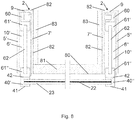
- FIGS. 5 to 8 is the extended state of the shading system BA, shown with the drop tube 23 in the lower end position FU (corresponds to the sequence point A5).
- the downcomer position is not always shown, but according to the views described above in words, it is indicated where the downcomer is located. Certain views may also occur in a different position of the drop tube in an identical manner.
- FIG. 9 shows the transition when lowering the tissue 22 from in the FIGS. 1 to 4 to the in the FIGS. 5 to 8 represent state shown.
- the transient state of the shading system BU with the drop tube 23 in the upper end position FO is in FIG. 9 shown, this corresponds to the sequence point A2.
- FIG. 10 shows the extended state of the shading system BA with the drop tube 23 in the intermediate position FZ, which corresponds to the sequence point A4.
- FIG. 1 is shown how the arrangement with top view of the outside 80 of the facade shows. Visible are the various elements that are arranged on the surface of the outside 80 of the facade. In the center is the window 81. Laterally there are the guide rails 40 'and 40 ".” On the guide rails 40', 40 ", that is, the outer side 41 of the guide rail, said apertures can be mounted. At the upper end of the window 81, the closure flap 11 is arranged. The arrangement as shown is integrated directly into the facade.
- FIG. 1 schematically indicated by reference numerals with dashed lines.
- the upper end is the upper end 4 of the mounting box 2.
- the left and right lateral ends 5 ', 5 "of the mounting box 2 which is from the main box 3 into the left and right lateral box parts 10', 10". of the mounting box 2 is enough.
- the lower end is located in the lateral box parts 10 of the left and right lower end 6 ', 6 "of the mounting box 2.
- Inside the side box parts 10', 10" of the mounting box 2 are the left and right lateral inner End 7 ', 7 "of the mounting box 2, between these two statements at the bottom of the main box 3 is the lower end 8 of the main box 3 of the mounting box. 2
- FIG. 2 is a look in the blind box 1 and the mounting box 2 shown. In this case, the view is shown as it is encountered when looking from the right side conclusion in the direction of the window 81 (position II im FIG. 1 ). This figure corresponds to a view into the lateral box part 10.
- the roller housing 20 is installed in the main box 3.
- the cylindrical roller 21 is mounted with the tissue 22 thereon, the roller 21 is in FIG. 2 indicated by dashed lines, since it is not visible.
- the roller 21 is laterally mounted in the roller housing 20 so that it can rotate about its longitudinal axis.
- the roller housing 20 in turn is attached to the mounting rail 60, which in turn is fixed to the rear end 9 of the mounting box 2.
- the roller housing 20 is not movably mounted.
- the mounting box 2 in turn is attached directly to the building on the inner facade level 82 and fixed to this immovable.
- the roller 21 is driven, that is, it can be rotated with the drive about an axis which corresponds to the longitudinal axis of the cylinder.
- the drive is a motor which is arranged directly in the roller 21 in it.
- the outside 80 of the facade is shown. This is continued by the flap 11 and the guide rails 40.
- the closure flap 11 is fastened in the present case with a hinge 12 at the upper end 4 of the mounting box 2. As shown, it is vertically aligned in the retracted state of the shading system BE and lies with its inside on the baffle 45, on the outer connecting rail 44 ', the upper vertical extension 43 of the guide rail 40 and the guide rails 40 at.
- the guide rail 40 is connected to the fastening rail 60 by means of the fastening profiles 61 ', 61 "and the guide rod 62.
- fastening profiles 61', 61" are attached to the guide rail 40 and to the fastening rail 60, which are connected to one another by a guide rod 62 .
- the guide rail 40 bears against the stop 63, which defines the end position.
- the inner side 42 of the guide rail 40 bears against the stop 63, while the outer side 41 of the guide rail 40 forms part of the outer side 80 of the facade.
- the fixed connection of the fastening profile 61 'with the fastening rail 60 which in turn is fixed to the rear end 9 of the mounting box 2 and thus with the inner wall plane 82, entails that the guide rod 62 rotates about this fastening profile 61'.
- the direction of rotation of the guide rod 62 is in the FIG. 2 with R indicated. Turning center is here as the attachment profile 61 '.
- the stopper profile 46 and the upper vertical extension 43 of the guide rail 40 is arranged. Behind the stopper profile 46 in the extension of the guide rails 40 in the direction of the FIG. 2 the connecting strips 44 and the stop plate 47 are arranged, these are not visible in the present view. Next is behind the vertical extension 43 of the guide rail 40 in the direction of the FIG. 2 arranged the baffle 45, which is also not visible in the present view.
- the lower end of the guide rail 40 is approximately at the same height as the lower end 6 of the mounting box 2.
- the mounting box 2 is shown in FIG. 2 with different elements.
- the upper end 4 of the mounting box 2, and this set against the lower end 8 of the main box 3 of the mounting box 2 is shown.
- the rear end 9 of the mounting box 2 is shown, this continues seamlessly into the already mentioned elements of the mounting box 2 and also directly in the lower end 6 of the mounting box 2.
- the lower end 6 of the mounting box 2 as well as the lower end 8 of the main box 3 is as in FIG. 2 shown inclined. This makes it possible that at most in the mounting box 2 collecting water from the mounting box 2 is derived. So that this water then does not get into the facade, the lower end 6 of the mounting box 2 is continued until the facade - he has as a conclusion a curved drainage edge.
- the most visible element of the mounting box 2 is the lateral inner end 7 of the mounting box 2, this continues from the lower end 6 of the mounting box 2 to the lower end 8 of the main box.
- FIG. 3 is a section through the main box 3 of the mounting box 2 and through the Storenkasten 1 and the mechanism shown. The cut lies in the middle of the window 81 or in the middle of the roller 21 (see position III in FIG. 1 ).
- FIG. 2 shows that the leadership of the fabric 22 from the roller 21 through the connecting strips 44 ', 44 "to the downpipe 23 is more visible and that also more details such as the arrangement of the stop profile 46 and the stop plate 47, and the upper vertical extension 43rd and the baffle 45 are visible.
- the roll 21 is cut but stylized as a full roll.
- the roller 21 is preferably not designed as a solid body, because in it, among other things, the drive is arranged. Also not shown in detail is the reeling of the fabric 22 on the roll 21, which is known to the skilled person and the general public from everyday use.
- the drop tube 23 is shown as a solid profile, this is also stylized, since the attachment of the fabric is assumed to be known and will not be further described at this point.
- the fabric 22 passes from the roll 21 between the outer tie bar 44 'and the inner tie bar 44 ", before it enters the guide rail 40 and is secured to the drop tube 23.
- the fabric 22 is unrolled from the roller 21 when the roller 21 rotates in the direction of rotation DS. Conversely, in the rotation in the direction of rotation DO, the fabric 22 is rolled up onto the roll 21.
- the drop tube 23 is shown in its upper end position FO. It is in abutment with the outer and inner connecting bars 44 ', 44 ".
- the drop tube 23 is connected to the fabric 22 by known means.
- the stop plate 47 is formed, which continues the inner connecting bar 44" in the direction of the inner facade plane 82 or is attached seamlessly thereto.
- the stop profile 46 together with the stop plate 47 form the positioning element for the guide frame 48, in the extended state of the shading system BA.
- the elements of the house are stylized and shown purely schematically.
- a wall element lies above the window 81 and the further window 84.
- Die various elements of the house are arranged so that in the facade a in plan view (such as in Fig. 1 and 5 ), forms a U-shaped recess.
- the different elements can be replaced by other or several others.
- the window 81 is located in the arrangement below the lower end 8 of the main box 3 of the mounting box 2.
- the sectional view shows in comparison with FIG. 2 also that two fastening rails 60 are used, one each left and right of the lower end 8 of the main box 3 of the mounting system. This also means that in each lateral box part 10 ', 10 "is attached a fixing rail 60. In the sectional view in this figure, the left fixing rail is visible while in the FIG. 2 the right mounting rail was visible.
- roller 21 In the roller housing 20, the roller 21 is visible in a sectional view.
- the drive of the roller 21 is at the left or right end of the roller 21 in the roller 21 in it, that is actually arranged visible in section of the corresponding location. The drive is not shown.
- FIG. 4 again the retracted state of the shading system BE is shown, this time in a horizontal sectional view.
- the fabric 22 and the drop tube 23 are realized between the left and right guide rails 40', 40" without further support.
- the fastening profiles 61 are fastened.
- the guide rod 62 is attached, which due to the assembly rotates about the mounted on the mounting rail 60 mounting profile 61 '.
- the stop 63 which rests directly on the inside 42 of the guide rail 40 ', 40 ", while the outside 41 of the guide rail 40 forms part of the outside 80 of the facade.
- the also visible window 81 in a sectional view, is mounted between the lateral box parts 10 ', 10 "of the mounting box 2. Combined with the other figures, it can be seen that the window 81 and the other facade elements (wall elements 83) on three sides of Mounting box 2 are included., Thus, the window 81 is finally shaded.
- the different side walls of the mounting box 2 are also visible in the corresponding lateral box parts 10 ', 10 "in this view from the mounting box 2.
- the left side box part 10' the left side end 5 'and the left side inside end 7' of the mounting box 2 visible, while in the right side box part 10 "the right side closure 5" and the right side inner end 7 “of the mounting box 2 are visible.
- the lower left end 6 'of the mounting box 2 and in the right side box part 10" the right lower end 6 "of the mounting box 2 can be recognized.
- FIG. 5 The extended state of the shade system BA with the drop tube 23 in the) lower end position FU is shown in FIG FIG. 5 in a plan view of the outside 80 the facade shown.
- the system is no longer completely arranged in the facade, which is shown in various details, but can be better recognized in the following figures.
- the closure flap 11 can be seen, which is arranged in this state at an angle to the facade (in this view, recognizable by the smaller projected area compared with FIG FIG. 1 ).
- the window 81 is not visible in this view because it is hidden by the fully extended tissue 22.
- the fabric 22 shows itself after passing through the connecting strips 44 ', 44 "on the outside 80 of the facade.
- the outer connecting strip 44' is visible in the view, directly above the baffle 45 is arranged.
- the drop tube 23 is in its lower end position U, which is located at the end of the guide rails 40 ', 40 ", which are now slightly lower than in the retracted state of the shading system BE, this is shown in FIG FIG. 5 Recognized that the lower ends of the guide rails 40 ', 40 "are no longer in the continuation of the facade structure.
- the vertical upper extension of the guide rail 43 and the stopper profile 46 are not specifically shown in this view due to their thin design.
- FIGS. 6 . 7 and 8th show in analogous views to the previous ones Figures 2 . 3 and 4 the shading system or parts thereof, but in a different condition.
- FIG. 6 is a look in the blind box 1 and the mounting box 2 shown. The view is shown as it is encountered when looking from the right side conclusion in the direction of the window 81.
- FIG. 7 is a section through the main box 3 of the mounting box 2 and through the Storenkasten 1 and the mechanism shown. The cut lies in the middle of the window 81 or in the middle of the roller 21.
- FIG. 8 is again the extended state of the shading system BA shown, this time in a horizontal sectional view.
- FIG. 6 is specifically seen that the stopper 63 is free, he has no function in the extended state of the shading system BA.
- the lower end of the guide frame 48 or the lower end of the guide rails 40 is lower than the lower end 6 of the mounting box 2.
- the fabric 22 is at least partially unrolled from the roll 21, in part because the Tissue 22 is usually slightly longer in length than the length actually required and thus still a portion of the fabric 22 is on the roller 21.
- the fabric 22 is passed between the inner and outer tie bars 44 ', 44 "and is thereafter guided in the guide rail 40.
- the lower end of the fabric 22, which is located in the drop tube 23, is not shown.
- the stopper profile 46 rests against the lower end 8 of the main body 3 as already described.
- the mounting profiles 61 with the guide rods 62 carry no weight, they are responsible only for the positioning of the guide frame 48. The weight is supported by the stopper profile 46 and the stopper plate 47.
- FIG. 8 If the arrangement of the mechanism for the movement of the guide rails 40 ', 40 ", which are located to the left and right of the window 81, is clearly visible, it is clearly visible how they are located in opposite directions FIG. 4 another position or other relative arrangement.
- the extended state of the shading system BA is shown.
- both the fabric 22 and the downpipe 23 are guided in the guide rails 40 'and 40 ", respectively.
- the further facade is in the FIGS. 4 and 8th Not shown. Basically, this connects directly to the mounting box 2, this is namely embedded in the facade. Wall elements of the house 83 and further windows 84 are shown schematically.
- FIG. 9 the transitional state of the shading system BU is shown with the drop tube 23 in the upper end position FO.
- the illustration is a section through the main box 3 of the mounting box 2 or through the blind box 1 and the mechanics. The cut is in the middle of the window 81 or in the middle of the roller 21st
- the stop profile 46 or the stop plate 47 is not yet in abutment lower end 8 of the main box 3.
- the drop tube 23 is still in the upper end position FO.
- the position of the drop tube 23 is due to the fact that the guide frame 48 can still move and the position of the drop tube 23 does not change, as long as the guide frame 48 can be moved.
- the entire weight of the guide frame 48 is transmitted through the drop tube 23 on the fabric 22 and so on the roller 21.
- the bearings of the roller then transferred to the roller housing 20, which transmits to the mounting box 2. This leads the power over the screw connection on the facade of the building.
- FIG. 10 shows at the same position as FIG. 9 the shading system in its extended state BA and the downpipe 23 in an intermediate position FZ.
- the representation is in turn a section through the main box 3 of the mounting box 2 or through the blind box 1 and the mechanics.
- the cut is in the middle of the window 81 or in the middle of the roller 21st
- While the drop tube 23 is in an intermediate position FZ, it is in the guide rail 40 and not in the upper and not in the lower end position FU, FO.
- the intermediate position FZ of the downpipe 23 allows at least partial shading.
- the drop tube 23 is in an intermediate position FZ until it reaches the lower end position FU of the drop tube 23, that is, until the tissue 22 does not continue to roll.
Landscapes
- Engineering & Computer Science (AREA)
- Structural Engineering (AREA)
- Architecture (AREA)
- Civil Engineering (AREA)
- Operating, Guiding And Securing Of Roll- Type Closing Members (AREA)
Claims (15)
- Système d'ombrage contenant :un arbre (21),une surface (22) de protection contre la lumière, flexible, apte à être enroulée sur l'arbre (21) et destinée à couvrir la surface (81) d'une fenêtre,un moteur d'entraînement qui entraîne l'arbre (21),un dispositif mobile de guidage (28) apte à être enfoncé dans une façade (80) et présentant deux rails latéraux de guidage (40) maintenus à distance l'un de l'autre et guidant latéralement la protection (22) contre la lumière à enrouler, chacun des rails de guidage (40) étant raccordé aux bras pivotant (62),caractérisé en ce quele système d'ombrage contient un élément flexible de traction (22) qui peut être enroulé sur un arbre (21) entraîné par un moteur d'entraînement,en ce que le dispositif de guidage (48) est relié fonctionnellement à l'élément flexible de traction (22) de telle sorte que le dispositif de guidage (48) puisse être déployé en avant de la façade (80) sous l'action de la gravité par le déroulement de l'élément de traction (22) hors de l'arbre (21) et puisse être rabattu en retrait la façade (80) par la force de traction de l'élément de traction (22) lors de l'enroulement de l'élément de traction (22).
- Système d'ombrage selon la revendication 1, caractérisé en ce que l'arbre (21) prévu pour l'élément de traction (22) et l'arbre (21) prévu pour la surface (22) de protection contre la lumière sont entraînés par un entraînement commun.
- Système d'ombrage selon les revendications 1 ou 2, caractérisé en ce que l'élément de traction (22) et la surface (22) de protection contre la lumière peuvent être enroulés sur un arbre (21) commun.
- Système d'ombrage selon l'une des revendications 1 à 3, caractérisé en ce que l'élément de traction (22) est formé par la surface (22) de protection contre la lumière.
- Système d'ombrage selon l'une des revendications 1 à 4, caractérisé en ce que le système d'ombrage contient un caisson principal (3) permettant de l'installer dans une découpe formée dans une façade (80) et en ce que l'arbre (21) sur lequel l'élément de traction (22) et/ou l'arbre (21) sur lequel la protection (22) contre la lumière peut être enroulée sont fixés dans le caisson principal (3).
- Système d'ombrage selon l'une des revendications 1 à 5, caractérisé en ce que le caisson principal (3) peut être fermé par un clapet de fermeture (11) qui peut être déplacé dans une position d'ouverture par sortie du dispositif de guidage (48), et dans une position de fermeture lors de la rentrée du dispositif de guidage (48) par gravité.
- Système d'ombrage selon la revendication 4, caractérisé en ce que la surface (22) de protection contre la lumière est lestée par un élément de lestage (23) pour un déroulement hors de l'arbre (21) à l'aide de la gravité, et en ce que l'élément de lestage (23) est en même temps un élément de retenue par lequel le dispositif de guidage (48) est maintenu lors de son déploiement et de son retrait.
- Système d'ombrage selon la revendication 7, caractérisé en ce que le dispositif de guidage (48) contient un organe de retenue (44', 44") qui coopère avec l'élément de lestage (23), l'organe de retenue (44', 44') étant configuré de telle sorte que le dispositif de guidage (48) soit maintenu par l'élément de lestage (23) qui vient se placer sur l'organe de retenue (44', 44") lors du déploiement et du retrait.
- Système d'ombrage selon l'une des revendications 1 à 8, caractérisé en ce que le système d'ombrage contient au moins un capteur de force qui mesure le couple de rotation du moteur d'entraînement de l'élément de traction (22) et/ou de la protection (22) contre la lumière, en vue de détecter que le dispositif de guidage (48) est tracté est en position d'extrémité.
- Système d'ombrage selon l'une des revendications 1 à 9, caractérisé en ce que le système d'ombrage contient un commutateur de position finale qui saisit la position d'extrémité de la protection (22) contre la lumière qui a été déroulée.
- Système d'ombrage selon l'une des revendications 1 à 10, caractérisé en ce que le système d'ombrage est configuré comme unité de montage et en ce que les arbres (21), les entraînements, la protection (22) contre la lumière, l'élément de traction (22), le dispositif de guidage (48) ainsi que l'ensemble de pivotement (62) sont placés dans un caisson de montage (2).
- Système d'ombrage selon la revendication 11, caractérisé en ce que le caisson de montage (2) présente la forme d'un U et contient deux parties latérales de caisson (10', 10") disposées à distance l'une de l'autre, reliées chacune aux rails de guidage (41) par l'ensemble de pivotement (62), ainsi qu'un caisson principal (3) qui s'étend transversalement par rapport aux parties (10', 10") de caisson et reliant l'une à l'autre les deux parties (10', 10") du caisson, et qui contient les arbres (21) prévus pour la protection (22) contre la lumière et pour le moyen de traction (22).
- Système d'ombrage selon l'une des revendications 1 à 12, caractérisé en ce que le dispositif de guidage (48) contient un organe de butée (47) par lequel le dispositif de guidage (48) repose contre un composant du caisson de montage (2) ou contre la façade lorsqu'il est déployé.
- Ouvrage de construction, en particulier bâtiment, contenant :une façade présentant une surface (80) de façade et au moins une surface (81) de fenêtre,un système d'ombrage selon l'une des revendications 1 à 13 qui ombre la surface (81) de la fenêtre,la surface de la façade étant configurée avec la surface extérieure de la ou des surfaces (81) de fenêtre par le fait que cette dernière est alignée sur la surface (80) de la façade et que le système d'ombrage est disposé en retrait de la surface (80) de la façade lorsqu'il est en position rétractée (BE) et en avant de la surface (80) de la façade lorsqu'il est en position déployée (BA).
- Ouvrage de construction selon la revendication 14, caractérisé en ce que des découpes allongées sont prévues dans la façade au-dessus et sur le côté de la surface de fenêtre, pour permettre d'enfoncer le système d'ombrage et le dispositif de guidage (48) en retrait par rapport à la surface (80) de la façade.
Priority Applications (1)
| Application Number | Priority Date | Filing Date | Title |
|---|---|---|---|
| EP14746938.1A EP3027835B1 (fr) | 2013-07-31 | 2014-07-16 | Système d'ombrage motorisé |
Applications Claiming Priority (3)
| Application Number | Priority Date | Filing Date | Title |
|---|---|---|---|
| EP13405099.6A EP2832950A1 (fr) | 2013-07-31 | 2013-07-31 | Système d'ombrage motorisé |
| PCT/CH2014/000111 WO2015013830A1 (fr) | 2013-07-31 | 2014-07-16 | Système d'ombrage motorisé |
| EP14746938.1A EP3027835B1 (fr) | 2013-07-31 | 2014-07-16 | Système d'ombrage motorisé |
Publications (2)
| Publication Number | Publication Date |
|---|---|
| EP3027835A1 EP3027835A1 (fr) | 2016-06-08 |
| EP3027835B1 true EP3027835B1 (fr) | 2017-08-23 |
Family
ID=48998556
Family Applications (2)
| Application Number | Title | Priority Date | Filing Date |
|---|---|---|---|
| EP13405099.6A Withdrawn EP2832950A1 (fr) | 2013-07-31 | 2013-07-31 | Système d'ombrage motorisé |
| EP14746938.1A Active EP3027835B1 (fr) | 2013-07-31 | 2014-07-16 | Système d'ombrage motorisé |
Family Applications Before (1)
| Application Number | Title | Priority Date | Filing Date |
|---|---|---|---|
| EP13405099.6A Withdrawn EP2832950A1 (fr) | 2013-07-31 | 2013-07-31 | Système d'ombrage motorisé |
Country Status (2)
| Country | Link |
|---|---|
| EP (2) | EP2832950A1 (fr) |
| WO (1) | WO2015013830A1 (fr) |
Family Cites Families (8)
| Publication number | Priority date | Publication date | Assignee | Title |
|---|---|---|---|---|
| AT176663B (de) * | 1952-07-17 | 1953-11-10 | Ant Schwarz Bau U Kunstschloss | Rolladen mit selbsttätiger Ausspreizvorrichtung |
| DE3403920A1 (de) * | 1984-02-04 | 1986-01-02 | Manfred 7321 Birenbach Nauerz | Jalousie fuer fenster- oder tueroeffnungen von bauwerken |
| DE3900745A1 (de) * | 1989-01-12 | 1990-07-19 | Hertel Kg | Ausstellbarer rolladen |
| FR2792360B1 (fr) * | 1999-04-13 | 2001-12-21 | Zurfluh Feller | Procede pour la mise en place d'un bloc baie comportant un coffre de volet roulant |
| DE102004032724A1 (de) | 2004-07-07 | 2006-02-16 | Stobag | Beschattungsvorrichtung |
| IT1404718B1 (it) | 2011-02-25 | 2013-11-29 | Ct Gibus Srl | Schermo avvolgibile. |
| DE202011102653U1 (de) * | 2011-06-30 | 2012-07-04 | Reiner Detenhoff Gmbh & Co. Kg | Rollladen, insbesondere Vorbaurollladen |
| CH705736B1 (de) | 2011-11-11 | 2015-12-15 | Biene Ag Winikon | Bauwerk mit Mehrfach-Isolierverglasung und Sonnenstore. |
-
2013
- 2013-07-31 EP EP13405099.6A patent/EP2832950A1/fr not_active Withdrawn
-
2014
- 2014-07-16 WO PCT/CH2014/000111 patent/WO2015013830A1/fr active Application Filing
- 2014-07-16 EP EP14746938.1A patent/EP3027835B1/fr active Active
Also Published As
| Publication number | Publication date |
|---|---|
| EP2832950A1 (fr) | 2015-02-04 |
| WO2015013830A1 (fr) | 2015-02-05 |
| EP3027835A1 (fr) | 2016-06-08 |
Similar Documents
| Publication | Publication Date | Title |
|---|---|---|
| DE102012211199B4 (de) | Rollladen, insbesondere Vorbaurollladen | |
| EP1913225B1 (fr) | Volet roulant pour une lucarne | |
| DE102012221860B4 (de) | Markise | |
| EP2896763B1 (fr) | Dispositif de protection pivotant extensible | |
| EP3027835B1 (fr) | Système d'ombrage motorisé | |
| DE19840418A1 (de) | Sonnenschutzvorrichtung | |
| EP3144464A1 (fr) | Dispositif de guidage pour volets roulants | |
| DE102014014342A1 (de) | Rolladen insbesondere Dachflächenfensterrollladen | |
| EP1762692A2 (fr) | Cadre dormant | |
| DE102012017000B4 (de) | Lichteinlassende Beschattungseinrichtung für Dachfenster | |
| EP2045424B1 (fr) | Dispositif de pivotement d'une paroi haute pivotante | |
| DE202005013342U1 (de) | Dachfenster, insbesondere für Wohnwagen | |
| EP3000956B1 (fr) | Tablier de volet roulant utilisable en jalousie | |
| DE19649550B4 (de) | Fenstervorrichtung für Bauwerke | |
| DE19830195B4 (de) | Verschlusseinrichtung für Einfahröffnungen, insbesondere von Garagen | |
| EP1225286B1 (fr) | Couverture extensible pour véranda | |
| DE202009009925U1 (de) | Gelenkarmmarkise mit zusätzlichem Sonnenschutz | |
| EP3118408B1 (fr) | Systeme de volet roulant | |
| DE102010035700A1 (de) | Rollladen | |
| DE102008028296A1 (de) | Fassadenmarkise | |
| DE202004005166U1 (de) | Schutzvorrichtung für Fenster und Türen | |
| EP3954855A1 (fr) | Fenêtre de louvre pourvu de dispositif de recouvrement | |
| DE102022103533A1 (de) | Beschattungsvorrichtung | |
| CH705736B1 (de) | Bauwerk mit Mehrfach-Isolierverglasung und Sonnenstore. | |
| DE102015220479A1 (de) | Kassette mit Markise und vertikalem Sonnenschutz |
Legal Events
| Date | Code | Title | Description |
|---|---|---|---|
| PUAI | Public reference made under article 153(3) epc to a published international application that has entered the european phase |
Free format text: ORIGINAL CODE: 0009012 |
|
| 17P | Request for examination filed |
Effective date: 20160201 |
|
| AK | Designated contracting states |
Kind code of ref document: A1 Designated state(s): AL AT BE BG CH CY CZ DE DK EE ES FI FR GB GR HR HU IE IS IT LI LT LU LV MC MK MT NL NO PL PT RO RS SE SI SK SM TR |
|
| AX | Request for extension of the european patent |
Extension state: BA ME |
|
| DAX | Request for extension of the european patent (deleted) | ||
| GRAP | Despatch of communication of intention to grant a patent |
Free format text: ORIGINAL CODE: EPIDOSNIGR1 |
|
| STAA | Information on the status of an ep patent application or granted ep patent |
Free format text: STATUS: GRANT OF PATENT IS INTENDED |
|
| RIC1 | Information provided on ipc code assigned before grant |
Ipc: E06B 9/58 20060101AFI20170130BHEP Ipc: E06B 9/42 20060101ALI20170130BHEP |
|
| INTG | Intention to grant announced |
Effective date: 20170217 |
|
| GRAS | Grant fee paid |
Free format text: ORIGINAL CODE: EPIDOSNIGR3 |
|
| GRAA | (expected) grant |
Free format text: ORIGINAL CODE: 0009210 |
|
| STAA | Information on the status of an ep patent application or granted ep patent |
Free format text: STATUS: THE PATENT HAS BEEN GRANTED |
|
| AK | Designated contracting states |
Kind code of ref document: B1 Designated state(s): AL AT BE BG CH CY CZ DE DK EE ES FI FR GB GR HR HU IE IS IT LI LT LU LV MC MK MT NL NO PL PT RO RS SE SI SK SM TR |
|
| REG | Reference to a national code |
Ref country code: GB Ref legal event code: FG4D Free format text: NOT ENGLISH |
|
| REG | Reference to a national code |
Ref country code: CH Ref legal event code: EP |
|
| REG | Reference to a national code |
Ref country code: AT Ref legal event code: REF Ref document number: 921546 Country of ref document: AT Kind code of ref document: T Effective date: 20170915 |
|
| REG | Reference to a national code |
Ref country code: IE Ref legal event code: FG4D Free format text: LANGUAGE OF EP DOCUMENT: GERMAN |
|
| REG | Reference to a national code |
Ref country code: DE Ref legal event code: R096 Ref document number: 502014005176 Country of ref document: DE |
|
| REG | Reference to a national code |
Ref country code: CH Ref legal event code: NV Representative=s name: FREI PATENTANWALTSBUERO AG, CH |
|
| REG | Reference to a national code |
Ref country code: NL Ref legal event code: MP Effective date: 20170823 |
|
| REG | Reference to a national code |
Ref country code: LT Ref legal event code: MG4D |
|
| PG25 | Lapsed in a contracting state [announced via postgrant information from national office to epo] |
Ref country code: HR Free format text: LAPSE BECAUSE OF FAILURE TO SUBMIT A TRANSLATION OF THE DESCRIPTION OR TO PAY THE FEE WITHIN THE PRESCRIBED TIME-LIMIT Effective date: 20170823 Ref country code: FI Free format text: LAPSE BECAUSE OF FAILURE TO SUBMIT A TRANSLATION OF THE DESCRIPTION OR TO PAY THE FEE WITHIN THE PRESCRIBED TIME-LIMIT Effective date: 20170823 Ref country code: NL Free format text: LAPSE BECAUSE OF FAILURE TO SUBMIT A TRANSLATION OF THE DESCRIPTION OR TO PAY THE FEE WITHIN THE PRESCRIBED TIME-LIMIT Effective date: 20170823 Ref country code: SE Free format text: LAPSE BECAUSE OF FAILURE TO SUBMIT A TRANSLATION OF THE DESCRIPTION OR TO PAY THE FEE WITHIN THE PRESCRIBED TIME-LIMIT Effective date: 20170823 Ref country code: NO Free format text: LAPSE BECAUSE OF FAILURE TO SUBMIT A TRANSLATION OF THE DESCRIPTION OR TO PAY THE FEE WITHIN THE PRESCRIBED TIME-LIMIT Effective date: 20171123 Ref country code: LT Free format text: LAPSE BECAUSE OF FAILURE TO SUBMIT A TRANSLATION OF THE DESCRIPTION OR TO PAY THE FEE WITHIN THE PRESCRIBED TIME-LIMIT Effective date: 20170823 |
|
| PG25 | Lapsed in a contracting state [announced via postgrant information from national office to epo] |
Ref country code: RS Free format text: LAPSE BECAUSE OF FAILURE TO SUBMIT A TRANSLATION OF THE DESCRIPTION OR TO PAY THE FEE WITHIN THE PRESCRIBED TIME-LIMIT Effective date: 20170823 Ref country code: LV Free format text: LAPSE BECAUSE OF FAILURE TO SUBMIT A TRANSLATION OF THE DESCRIPTION OR TO PAY THE FEE WITHIN THE PRESCRIBED TIME-LIMIT Effective date: 20170823 Ref country code: GR Free format text: LAPSE BECAUSE OF FAILURE TO SUBMIT A TRANSLATION OF THE DESCRIPTION OR TO PAY THE FEE WITHIN THE PRESCRIBED TIME-LIMIT Effective date: 20171124 Ref country code: ES Free format text: LAPSE BECAUSE OF FAILURE TO SUBMIT A TRANSLATION OF THE DESCRIPTION OR TO PAY THE FEE WITHIN THE PRESCRIBED TIME-LIMIT Effective date: 20170823 Ref country code: PL Free format text: LAPSE BECAUSE OF FAILURE TO SUBMIT A TRANSLATION OF THE DESCRIPTION OR TO PAY THE FEE WITHIN THE PRESCRIBED TIME-LIMIT Effective date: 20170823 Ref country code: IS Free format text: LAPSE BECAUSE OF FAILURE TO SUBMIT A TRANSLATION OF THE DESCRIPTION OR TO PAY THE FEE WITHIN THE PRESCRIBED TIME-LIMIT Effective date: 20171223 Ref country code: BG Free format text: LAPSE BECAUSE OF FAILURE TO SUBMIT A TRANSLATION OF THE DESCRIPTION OR TO PAY THE FEE WITHIN THE PRESCRIBED TIME-LIMIT Effective date: 20171123 |
|
| PG25 | Lapsed in a contracting state [announced via postgrant information from national office to epo] |
Ref country code: DK Free format text: LAPSE BECAUSE OF FAILURE TO SUBMIT A TRANSLATION OF THE DESCRIPTION OR TO PAY THE FEE WITHIN THE PRESCRIBED TIME-LIMIT Effective date: 20170823 Ref country code: RO Free format text: LAPSE BECAUSE OF FAILURE TO SUBMIT A TRANSLATION OF THE DESCRIPTION OR TO PAY THE FEE WITHIN THE PRESCRIBED TIME-LIMIT Effective date: 20170823 Ref country code: CZ Free format text: LAPSE BECAUSE OF FAILURE TO SUBMIT A TRANSLATION OF THE DESCRIPTION OR TO PAY THE FEE WITHIN THE PRESCRIBED TIME-LIMIT Effective date: 20170823 |
|
| REG | Reference to a national code |
Ref country code: DE Ref legal event code: R097 Ref document number: 502014005176 Country of ref document: DE |
|
| PG25 | Lapsed in a contracting state [announced via postgrant information from national office to epo] |
Ref country code: SM Free format text: LAPSE BECAUSE OF FAILURE TO SUBMIT A TRANSLATION OF THE DESCRIPTION OR TO PAY THE FEE WITHIN THE PRESCRIBED TIME-LIMIT Effective date: 20170823 Ref country code: EE Free format text: LAPSE BECAUSE OF FAILURE TO SUBMIT A TRANSLATION OF THE DESCRIPTION OR TO PAY THE FEE WITHIN THE PRESCRIBED TIME-LIMIT Effective date: 20170823 Ref country code: SK Free format text: LAPSE BECAUSE OF FAILURE TO SUBMIT A TRANSLATION OF THE DESCRIPTION OR TO PAY THE FEE WITHIN THE PRESCRIBED TIME-LIMIT Effective date: 20170823 |
|
| PLBE | No opposition filed within time limit |
Free format text: ORIGINAL CODE: 0009261 |
|
| STAA | Information on the status of an ep patent application or granted ep patent |
Free format text: STATUS: NO OPPOSITION FILED WITHIN TIME LIMIT |
|
| REG | Reference to a national code |
Ref country code: FR Ref legal event code: PLFP Year of fee payment: 5 |
|
| 26N | No opposition filed |
Effective date: 20180524 |
|
| PG25 | Lapsed in a contracting state [announced via postgrant information from national office to epo] |
Ref country code: SI Free format text: LAPSE BECAUSE OF FAILURE TO SUBMIT A TRANSLATION OF THE DESCRIPTION OR TO PAY THE FEE WITHIN THE PRESCRIBED TIME-LIMIT Effective date: 20170823 |
|
| PG25 | Lapsed in a contracting state [announced via postgrant information from national office to epo] |
Ref country code: MT Free format text: LAPSE BECAUSE OF FAILURE TO SUBMIT A TRANSLATION OF THE DESCRIPTION OR TO PAY THE FEE WITHIN THE PRESCRIBED TIME-LIMIT Effective date: 20170823 |
|
| REG | Reference to a national code |
Ref country code: CH Ref legal event code: PCAR Free format text: NEW ADDRESS: POSTFACH, 8032 ZUERICH (CH) |
|
| PG25 | Lapsed in a contracting state [announced via postgrant information from national office to epo] |
Ref country code: MC Free format text: LAPSE BECAUSE OF FAILURE TO SUBMIT A TRANSLATION OF THE DESCRIPTION OR TO PAY THE FEE WITHIN THE PRESCRIBED TIME-LIMIT Effective date: 20170823 Ref country code: LU Free format text: LAPSE BECAUSE OF NON-PAYMENT OF DUE FEES Effective date: 20180716 |
|
| REG | Reference to a national code |
Ref country code: BE Ref legal event code: MM Effective date: 20180731 |
|
| REG | Reference to a national code |
Ref country code: IE Ref legal event code: MM4A |
|
| PG25 | Lapsed in a contracting state [announced via postgrant information from national office to epo] |
Ref country code: IE Free format text: LAPSE BECAUSE OF NON-PAYMENT OF DUE FEES Effective date: 20180716 |
|
| PG25 | Lapsed in a contracting state [announced via postgrant information from national office to epo] |
Ref country code: BE Free format text: LAPSE BECAUSE OF NON-PAYMENT OF DUE FEES Effective date: 20180731 |
|
| PG25 | Lapsed in a contracting state [announced via postgrant information from national office to epo] |
Ref country code: TR Free format text: LAPSE BECAUSE OF FAILURE TO SUBMIT A TRANSLATION OF THE DESCRIPTION OR TO PAY THE FEE WITHIN THE PRESCRIBED TIME-LIMIT Effective date: 20170823 |
|
| PG25 | Lapsed in a contracting state [announced via postgrant information from national office to epo] |
Ref country code: PT Free format text: LAPSE BECAUSE OF FAILURE TO SUBMIT A TRANSLATION OF THE DESCRIPTION OR TO PAY THE FEE WITHIN THE PRESCRIBED TIME-LIMIT Effective date: 20170823 |
|
| PG25 | Lapsed in a contracting state [announced via postgrant information from national office to epo] |
Ref country code: MK Free format text: LAPSE BECAUSE OF NON-PAYMENT OF DUE FEES Effective date: 20170823 Ref country code: HU Free format text: LAPSE BECAUSE OF FAILURE TO SUBMIT A TRANSLATION OF THE DESCRIPTION OR TO PAY THE FEE WITHIN THE PRESCRIBED TIME-LIMIT; INVALID AB INITIO Effective date: 20140716 Ref country code: CY Free format text: LAPSE BECAUSE OF FAILURE TO SUBMIT A TRANSLATION OF THE DESCRIPTION OR TO PAY THE FEE WITHIN THE PRESCRIBED TIME-LIMIT Effective date: 20170823 |
|
| PG25 | Lapsed in a contracting state [announced via postgrant information from national office to epo] |
Ref country code: AL Free format text: LAPSE BECAUSE OF FAILURE TO SUBMIT A TRANSLATION OF THE DESCRIPTION OR TO PAY THE FEE WITHIN THE PRESCRIBED TIME-LIMIT Effective date: 20170823 |
|
| PGFP | Annual fee paid to national office [announced via postgrant information from national office to epo] |
Ref country code: IT Payment date: 20220726 Year of fee payment: 9 Ref country code: GB Payment date: 20220721 Year of fee payment: 9 |
|
| PGFP | Annual fee paid to national office [announced via postgrant information from national office to epo] |
Ref country code: FR Payment date: 20220720 Year of fee payment: 9 |
|
| PGFP | Annual fee paid to national office [announced via postgrant information from national office to epo] |
Ref country code: CH Payment date: 20230801 Year of fee payment: 10 Ref country code: AT Payment date: 20230720 Year of fee payment: 10 |
|
| PGFP | Annual fee paid to national office [announced via postgrant information from national office to epo] |
Ref country code: DE Payment date: 20230719 Year of fee payment: 10 |
|
| GBPC | Gb: european patent ceased through non-payment of renewal fee |
Effective date: 20230716 |
|
| PG25 | Lapsed in a contracting state [announced via postgrant information from national office to epo] |
Ref country code: GB Free format text: LAPSE BECAUSE OF NON-PAYMENT OF DUE FEES Effective date: 20230716 |