EP3027445B1 - Fahrzeugtüraufbau - Google Patents
Fahrzeugtüraufbau Download PDFInfo
- Publication number
- EP3027445B1 EP3027445B1 EP14734934.4A EP14734934A EP3027445B1 EP 3027445 B1 EP3027445 B1 EP 3027445B1 EP 14734934 A EP14734934 A EP 14734934A EP 3027445 B1 EP3027445 B1 EP 3027445B1
- Authority
- EP
- European Patent Office
- Prior art keywords
- door
- main body
- body portion
- joining member
- inner panel
- Prior art date
- Legal status (The legal status is an assumption and is not a legal conclusion. Google has not performed a legal analysis and makes no representation as to the accuracy of the status listed.)
- Not-in-force
Links
- 229910052751 metal Inorganic materials 0.000 claims description 19
- 239000002184 metal Substances 0.000 claims description 19
- 239000011347 resin Substances 0.000 claims description 4
- 229920005989 resin Polymers 0.000 claims description 4
- 230000002093 peripheral effect Effects 0.000 description 5
- 239000000853 adhesive Substances 0.000 description 2
- 230000001070 adhesive effect Effects 0.000 description 2
- 238000005452 bending Methods 0.000 description 2
- 230000000694 effects Effects 0.000 description 2
- 238000000465 moulding Methods 0.000 description 2
- 239000004033 plastic Substances 0.000 description 2
- 229920003023 plastic Polymers 0.000 description 2
- 229920002430 Fibre-reinforced plastic Polymers 0.000 description 1
- 229910052782 aluminium Inorganic materials 0.000 description 1
- XAGFODPZIPBFFR-UHFFFAOYSA-N aluminium Chemical compound [Al] XAGFODPZIPBFFR-UHFFFAOYSA-N 0.000 description 1
- 239000004918 carbon fiber reinforced polymer Substances 0.000 description 1
- 239000006185 dispersion Substances 0.000 description 1
- 239000011151 fibre-reinforced plastic Substances 0.000 description 1
- 238000009957 hemming Methods 0.000 description 1
- 238000003466 welding Methods 0.000 description 1
Images


Classifications
-
- B—PERFORMING OPERATIONS; TRANSPORTING
- B60—VEHICLES IN GENERAL
- B60J—WINDOWS, WINDSCREENS, NON-FIXED ROOFS, DOORS, OR SIMILAR DEVICES FOR VEHICLES; REMOVABLE EXTERNAL PROTECTIVE COVERINGS SPECIALLY ADAPTED FOR VEHICLES
- B60J5/00—Doors
- B60J5/04—Doors arranged at the vehicle sides
- B60J5/0463—Conceptual assembling of door, i.e. how door frame parts should be fitted together to form door
-
- B—PERFORMING OPERATIONS; TRANSPORTING
- B60—VEHICLES IN GENERAL
- B60J—WINDOWS, WINDSCREENS, NON-FIXED ROOFS, DOORS, OR SIMILAR DEVICES FOR VEHICLES; REMOVABLE EXTERNAL PROTECTIVE COVERINGS SPECIALLY ADAPTED FOR VEHICLES
- B60J5/00—Doors
- B60J5/04—Doors arranged at the vehicle sides
- B60J5/042—Reinforcement elements
- B60J5/0422—Elongated type elements, e.g. beams, cables, belts or wires
- B60J5/0423—Elongated type elements, e.g. beams, cables, belts or wires characterised by position in the lower door structure
- B60J5/0427—Elongated type elements, e.g. beams, cables, belts or wires characterised by position in the lower door structure the elements being arranged along the lower edge of door
-
- B—PERFORMING OPERATIONS; TRANSPORTING
- B60—VEHICLES IN GENERAL
- B60J—WINDOWS, WINDSCREENS, NON-FIXED ROOFS, DOORS, OR SIMILAR DEVICES FOR VEHICLES; REMOVABLE EXTERNAL PROTECTIVE COVERINGS SPECIALLY ADAPTED FOR VEHICLES
- B60J5/00—Doors
- B60J5/04—Doors arranged at the vehicle sides
- B60J5/042—Reinforcement elements
- B60J5/0422—Elongated type elements, e.g. beams, cables, belts or wires
- B60J5/0423—Elongated type elements, e.g. beams, cables, belts or wires characterised by position in the lower door structure
- B60J5/0431—Elongated type elements, e.g. beams, cables, belts or wires characterised by position in the lower door structure the elements being arranged at the hinge area
-
- B—PERFORMING OPERATIONS; TRANSPORTING
- B60—VEHICLES IN GENERAL
- B60J—WINDOWS, WINDSCREENS, NON-FIXED ROOFS, DOORS, OR SIMILAR DEVICES FOR VEHICLES; REMOVABLE EXTERNAL PROTECTIVE COVERINGS SPECIALLY ADAPTED FOR VEHICLES
- B60J5/00—Doors
- B60J5/04—Doors arranged at the vehicle sides
- B60J5/042—Reinforcement elements
- B60J5/0422—Elongated type elements, e.g. beams, cables, belts or wires
- B60J5/0437—Elongated type elements, e.g. beams, cables, belts or wires characterised by the attachment means to the door, e.g. releasable attachment means
-
- B—PERFORMING OPERATIONS; TRANSPORTING
- B60—VEHICLES IN GENERAL
- B60J—WINDOWS, WINDSCREENS, NON-FIXED ROOFS, DOORS, OR SIMILAR DEVICES FOR VEHICLES; REMOVABLE EXTERNAL PROTECTIVE COVERINGS SPECIALLY ADAPTED FOR VEHICLES
- B60J5/00—Doors
- B60J5/04—Doors arranged at the vehicle sides
- B60J5/042—Reinforcement elements
- B60J5/0422—Elongated type elements, e.g. beams, cables, belts or wires
- B60J5/0438—Elongated type elements, e.g. beams, cables, belts or wires characterised by the type of elongated elements
- B60J5/0443—Beams
- B60J5/0445—Beams formed of several elements arranged in series
-
- B—PERFORMING OPERATIONS; TRANSPORTING
- B60—VEHICLES IN GENERAL
- B60J—WINDOWS, WINDSCREENS, NON-FIXED ROOFS, DOORS, OR SIMILAR DEVICES FOR VEHICLES; REMOVABLE EXTERNAL PROTECTIVE COVERINGS SPECIALLY ADAPTED FOR VEHICLES
- B60J5/00—Doors
- B60J5/04—Doors arranged at the vehicle sides
- B60J5/048—Doors arranged at the vehicle sides characterised by the material
- B60J5/0481—Doors arranged at the vehicle sides characterised by the material plastic
-
- B—PERFORMING OPERATIONS; TRANSPORTING
- B60—VEHICLES IN GENERAL
- B60J—WINDOWS, WINDSCREENS, NON-FIXED ROOFS, DOORS, OR SIMILAR DEVICES FOR VEHICLES; REMOVABLE EXTERNAL PROTECTIVE COVERINGS SPECIALLY ADAPTED FOR VEHICLES
- B60J5/00—Doors
- B60J5/04—Doors arranged at the vehicle sides
- B60J5/048—Doors arranged at the vehicle sides characterised by the material
- B60J5/0484—Doors arranged at the vehicle sides characterised by the material hybrid, i.e. plastic moulded onto metal parts
Definitions
- the present invention relates to a vehicle door structure according to the preamble of claim 1.
- a vehicle door structure is known from EP 2 199 128 A .
- an object of the present invention is to obtain a vehicle door structure in which breakage of a door inner panel can be suppressed even if load, that is directed toward a door thickness direction inner side, is applied to a beam that is provided within a door main body portion.
- a vehicle door structure relating to a first aspect of the present invention has: a door inner panel that is made of resin and that, together with a door outer panel, structures a door main body portion having a closed cross-sectional shape; a beam having a frame main body portion, that extends in a door longitudinal direction, and a frame extended portion, that is made of metal and is provided in continuation with a length direction end portion of the frame main body portion, the frame being disposed within the closed cross-section of the door main body portion; and a bent portion that is bendingly or curvingly molded at the frame extended portion, and that, as seen in plan view, is disposed further toward a door thickness direction outer side or inner side than the frame main body portion.
- the bent portion that is disposed further toward the door thickness direction outer side or inner side than the frame main body portion as seen in plan view, is bendingly or curvingly molded at the frame extended portion that is made of metal. Accordingly, at the time of a side collision of the vehicle, even if load, that is directed toward the door thickness direction inner side, is applied to the beam that is provided within the closed cross-section of the door main body portion, due to the bent portion of the frame extended portion being elongated rectilinearly, that load is absorbed efficiently. Accordingly, breakage (the occurrence of breaks or cracks) of the door inner panel is suppressed.
- a joining member that is made of metal is provided at the door inner panel so as to close-off an opening portion formed in the door inner panel, and a free end portion of the frame extended portion is joined to the joining member.
- the joining member that is made of metal is provided so as to close-off the opening portion that is formed in the door inner panel, and the free end portion of the frame extended portion is joined to this joining member. Accordingly, when load, that is directed toward the door thickness direction inner side, is applied to the beam, the bent portion of the frame extended portion is elongated rectilinearly, and the joining member, that is exposed from the opening portion of the door inner panel, deforms. Accordingly, the load, that is directed toward the door thickness direction inner side and that is applied to the beam, is absorbed more efficiently, and breakage (the occurrence of breaks or cracks) of the door inner panel is suppressed more.
- a vehicle door structure relating to a second aspect of the present invention is the vehicle door structure of the first aspect, wherein the free end portion of the frame extended portion is joined to the joining member together with a door structural part that is for mechanically connecting the door main body portion to a vehicle main body.
- the free end portion of the frame extended portion is joined to the joining member together with a door structural part that is for mechanically connecting the door main body portion to the vehicle main body. Accordingly, at the time of a side collision of the vehicle or at the time of fitting the door main body portion to the vehicle main body, even if load is applied to the door structural part, the joining member that is exposed from the opening portion deforms, and that load is absorbed. Therefore, the load that is applied to the door inner panel is reduced. Accordingly, breakage (the occurrence of breaks or cracks) of the door inner panel at the region where the door structural part is joined is suppressed.
- the joining member that is made of metal is provided at the door inner panel only at the region thereof where the free end portion of the frame extended portion and the door structural part are joined. Therefore, the mass of the door main body portion is reduced efficiently while the support rigidity of the door main body portion with respect to the vehicle main body is ensured.
- a vehicle door structure relating to a third aspect is the vehicle door structure of any one of the first and second aspect, wherein the bent portion is formed in a wave shape as seen in plan view.
- the bent portion is formed in a wave shape as seen in plan view. Accordingly, when load, that is directed toward the door thickness direction inner side, is applied to the beam, the bent portion is elongated in a rectilinear shape even longer than a case in which the bent portion is not formed in a wave shape as seen in plan view. Accordingly, the load, that is directed toward the door thickness direction inner side and that is applied to the beam, is absorbed more efficiently, and breakage (the occurrence of breaks or cracks) of the door inner panel is suppressed more.
- arrow UP that is shown appropriately in the respective drawings is the door upward direction
- arrow FR is the door frontward direction
- arrow OUT is the door thickness direction outer side.
- vertical, longitudinal and inward/outward directions when vertical, longitudinal and inward/outward directions are used, they mean the vertical of the door vertical direction, the longitudinal of the door longitudinal direction, and the inward/outward of the door thickness direction unless otherwise stated.
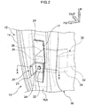
- a vehicle door structure 10 relating to the first embodiment has a door outer panel 14 that is made of metal and is provided at the door thickness direction outer side, and a door inner panel 16 that is made of a fiber reinforced plastic (made of an FRP), e.g., is made of a carbon fiber reinforced plastic (made of a CRFP), and is provided at the door thickness direction inner side and, together with the door outer panel 14, structures a door main body portion 12 that has a closed cross-sectional shape. Further, a door frame 18, that is made of metal and is formed in a frame shape, is provided at the upper portion of the door inner panel 16.
- a door outer panel 14 that is made of metal and is provided at the door thickness direction outer side
- a door inner panel 16 that is made of a fiber reinforced plastic (made of an FRP), e.g., is made of a carbon fiber reinforced plastic (made of a CRFP), and is provided at the door thickness direction inner side and, together with the door outer panel 14, structures a door main body portion 12 that has
- the front portion of the door inner panel 16 is bendingly molded in a substantial "Z" shape as seen in plan view.
- a front end portion 14F of the door outer panel 14 is joined by hemming processing to a front end portion 16F of the door inner panel 16 that projects-out toward the door front side at the door thickness direction outer side.
- the wall portion, that faces in the door longitudinal direction at the front portion of the door inner panel 16 is a front wall portion 16A.
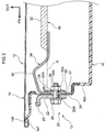
- the door hinge portion 20 has a hinge main body 22, that is made of metal and is an example of a door structural part for mechanically connecting the door main body portion 12 to the vehicle main body, and a joining member 24, that is described later and to whose front surface side the hinge main body 22 is mounted.
- the hinge main body 22 is formed in a substantially "L" shape as seen in plan view, and a cylindrical tubular portion 23, whose axial direction is the vertical direction, is integrally continuous with a distal end portion that projects-out toward the door front side. Note that, because the structures of the upper and lower door hinge portions 20, including the hinge main bodies 22, are the same, only the door hinge portion 20 at the lower side is described hereinafter.
- the joining member 24 is formed in the shape of a plate that is one size larger than the opening portion 17, and the peripheral edge portion of the joining member 24 is embedded integrally within the plate thickness of the front wall portion 16A surrounding the opening portion 17. Therefore, the plate thickness at the front wall portion 16A of the door inner panel 16 is formed to be thicker than the plate thickness of the joining member 24 (see Fig. 3 ).
- the peripheral edge portion of the joining member 24 is bendingly molded so as to match the shape of the front wall portion 16A of the door inner panel 16 as seen in plan view. Namely, the peripheral edge portion at the door thickness direction outer side is bendingly molded so as to project-out toward the door front side, and the peripheral edge portion at the door thickness direction inner side is bendingly molded toward the door rear side, and in continuation therewith, is bendingly molded toward the door thickness direction inner side. Due thereto, the joining strength of the joining member 24 with respect to the door inner panel 16 is improved.
- a through-hole 24A that is for fastening the hinge main body 22 by a bolt 26 and a nut 28, is formed in the substantially central portion of the joining member 24 that is exposed from the opening portion 17.
- a through-hole 22A that communicates with the through-hole 24A of the joining member 24, is formed also in the hinge main body 22.
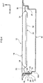
- an impact beam 30 that serves as a frame is disposed at the lower portion side within the closed cross-section of the door main body portion 12.
- the impact beam 30 has a beam main body portion (frame main body portion) 32, that is made of metal and extends in the door longitudinal direction, and beam extended portions (frame extended portions) 34 that are made of metal and are provided in continuation with the length direction both end portion sides of the beam main body portion 32.
- the beam main body portion 32 is molded integrally in cross-sectional "U" shape that opens toward the door thickness direction outer side.
- the beam extended portions 34 that are plate-shaped and have bent portions 36 that are described later, are joined integrally to (by welding or by fastening by bolts or the like) and are provided in continuation with the length direction both end portions of the beam main body portion 32.
- the front and rear beam extended portions 34 have substantially symmetrical shapes, in the following description, mainly the beam extended portion at the door hinge portion 20 side is used as an example, and the structure thereof is described.
- the beam extended portion 34 is formed so as to, as seen in plan view, be longer than a virtual extended straight line K that extends toward the door front side of the beam main body portion 32 until reaching the joining member 24. Further, at least a portion of the beam extended portion 34 other than a free end portion 35 thereof that is described later, is made to be the bent portion 36 that is bendingly molded so as to be disposed further toward the door thickness direction outer side than the beam main body portion 32 (the virtual extended straight line K).
- the bent portion 36 of the beam extended portion 34 is first bendingly molded from the front end portion side of the beam main body portion 32 toward the door thickness direction outer side, and subsequently, is bendingly molded toward the door front side. Further, the free end portion (the distal end portion further toward the door front side than the bent portion 36) 35, that is continuous from the bent portion 36 of the beam extended portion 34, is bendingly molded toward the door thickness direction inner side and faces in the door longitudinal direction.
- the free end portion 35 of the beam extended portion 34 is disposed at the rear surface side of the joining member 24. Further, a through-hole 35A, that communicates with the through-hole 24A of the joining member 24, is formed in the free end portion 35 of this beam extended portion 34.
- a retainer 38 made of metal is disposed at the rear surface side of the free end portion 35 of the beam extended portion 34. Further, a through-hole 38A, that communicates with the through-hole 24A of the joining member 24 and the through-hole 35A of the free end portion 35, is formed in this retainer 38. Accordingly, the free end portion 35 of the beam extended portion 34 is, together with the hinge main body 22, fastened and fixed to the joining member 24 as follows.
- the hinge main body 22 is disposed at the front surface side of the joining member 24, and the free end portion 35 of the beam extended portion 34 is disposed at the rear surface side of the joining member 24.
- the bolt 26 is inserted-through the through-hole 22A, the through-hole 24A, the through-hole 35A, the through-hole 38A from the door front side, and is screwed-together with the nut 28 that is provided at the rear surface side of the retainer 38. Due thereto, the hinge main body 22 and the free end portion 35 of the beam extended portion 34 are both fastened and fixed to the joining member 24.
- the nut 28 is made to be a weld nut that is fixed to the rear surface side of the retainer 38 coaxially with the through-hole 38A, but is not limited to this.
- the bent portion 36 is not limited to being formed the bent shape that is illustrated and may be formed, for example, in a curved shape (not illustrated) that is curved in a substantial circular arc shape as seen in plan view, or the like.
- the free end portion 35 of the beam extended portion 34 at the rear side is joined, by joining means such as an adhesive or an unillustrated bolt/nut or the like, to the door inner panel 16 or to a joining member that is made of metal and is provided so as to close-off an unillustrated opening portion.
- the inner diameter of the through-hole 35A that is formed in the free end portion 35 of the beam extended portion 34, is formed to be larger than the inner diameter of the through-hole 22A formed in the hinge main body 22 and the inner diameter of the through-hole 38A formed in the retainer 38. Due thereto, dispersion in the position of the beam extended portion 34 (the free end portion 35) with respect to the position at which the impact beam 30 is disposed is absorbed.
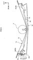
- the impact beam 30, that is disposed within the closed cross-section of the door main body portion 12, has the beam extended portions 34 at both the front and rear sides of the beam main body portion 32.
- the bent portion 36 that is disposed further toward the door thickness direction outer side than the beam main body portion 32, is bendingly molded at the beam extended portion 34 except for the free end portion 35 that is fastened and fixed (joined) to the joining member 24 (the door inner panel 16).
- breakage of the front wall portion 16A of the door inner panel 16 and in more detail, breakage (the generation of breaks or cracks) of the front wall portion 16A surrounding the opening portion 17 where the peripheral edge portion of the joining member 24 is embedded, can be suppressed or prevented.
- the opening portion 17 is formed in the front wall portion 16A of the door inner panel 16, and the joining member 24 is provided so as to close-off this opening portion 17. Further, the free end portion 35 of the beam extended portion 34 is fastened and fixed to the joining member 24 that is exposed from the opening portion 17.
- the collision load that is inputted to the impact beam 30 (the door main body portion 12) can be absorbed also by the plastic deformation (bending deformation) of the joining member 24 that is exposed from the opening portion 17. Accordingly, breakage of the front wall portion 16A surrounding the opening portion 17 can be suppressed or prevented further.
- the joining member 24 that is exposed from the opening portion 17 plastically deforms (bendingly deforms), and that load can be absorbed. Accordingly, in this case as well, load that is applied to the front wall portion 16A surrounding the opening portion 17 can be reduced, and breakage of the front wall portion 16A surrounding the opening portion 17 can be suppressed or prevented.
- the joining member 24 that is made of metal is provided only at the region where a door structural part (the hinge main body 22), that is for mechanically connecting the door main body portion 12 to the vehicle main body, is mounted. Accordingly, a decrease in the fastening force of the bolt 26 and the nut 28 due to the passage of time can be suppressed, and the support rigidity of the door main body portion 12 (the door hinge portion 20) with respect to the vehicle main body can be ensured, and the mass of the door main body portion 12 can be reduced efficiently.
- the beam extended portion 34 is made to be a bent portion 36-2 that is bendingly molded so as to be disposed further toward the door thickness direction inner side than the beam main body portion 32 (the virtual extended straight line K), as seen in plan view.
- this beam extended portion 34 also is formed so as to, as seen in plan view, be longer than the virtual extended straight line K that extends toward the door front side of the beam main body portion 32 until reaching the joining member 24.
- the bent portion 36-2 of the beam extended portion 34 is first bendingly molded from the front end portion side of the beam main body portion 32 toward the door thickness direction inner side, and subsequently, is bendingly molded toward the door front side. Further, the free end portion 35 of the beam extended portion 34 is further bendingly molded toward the door thickness direction outer side and is disposed at the rear surface side of the joining member 24.
- the bent portions 36-2 of the beam extended portions 34 at both front and rear sides may be structured so as to be disposed further toward the door thickness direction inner side than the beam main body portion 32.
- the bent portion 36-2 of the beam extended portion 34 at either one of the front or rear side is disposed further toward the door thickness direction inner side than the beam main body portion 32, and the bent portion 36-2 of the beam extended portion 34 at the other one of the front or rear side is disposed further toward the door thickness direction outer side than the beam main body portion 32.
- the beam extended portion 34 is made to be a bent portion 36-3 that is bendingly molded so as to be disposed further toward the door thickness direction outer side than the beam main body portion 32 (the virtual extended straight line K) as seen in plan view, and this bent portion 36-3 is formed in a wave shape as seen in plan view.
- this beam extended portion 34 also is formed so as to, as seen in plan view, be longer than the virtual extended straight line K that extends toward the door front side of the beam main body portion 32 until reaching the joining member 24.
- the bent portion 36-3 of the beam extended portion 34 is first bendingly molded from the front end portion side of the beam main body portion 32 toward the door thickness direction outer side, and subsequently (further toward the door thickness direction outer side than the virtual extended straight line K), is bendingly deformed in a wave-shape in the order of toward the door thickness direction inner side, the door thickness direction outer side, the door thickness direction inner side. Further, the free end portion 35 of the beam extended portion 34 is further bendingly molded toward the door thickness direction inner side and is disposed at the rear surface side of the joining member 24.
- the bent portion 36 can plastically deform so as to elongate in an even longer rectilinear shape than the beam extended portions 34 of the above-described first embodiment and second embodiment. Accordingly, the collision load that is inputted to the impact beam 30 (the door main body portion 12) can be absorbed even more efficiently.
- the wave-shape of the bent portion 36-3 in the third embodiment may be formed at the bent portion 36-2 in the second embodiment.
- the vehicle door structure 10 relating to the present embodiments has been described above on the basis of the drawings, but the vehicle door structure 10 relating to the present embodiments is not limited to the illustrated structures, and the design thereof can be changed appropriately within a scope that does not deviate from the gist of the present invention.
- the impact beam 30 may be structured so as to span between the door hinge portion 20 at the upper side and an unillustrated door lock portion (a joining member that is made of metal and to which an unillustrated lock main body is joined).
- the door structural part relating to the present embodiments is not limited to the hinge main body 22.
- the free end portion 35 of the beam extended portion 34 is not limited to a structure of being fastened, together with the door structural part (the hinge main body 22), to the joining member 24.
- the free end portion 35 of the beam extended portion 34 may be structured so as to be joined to the joining member 24 or the door inner panel 16, independently of the door structural part (the hinge main body 22).
- the beam extended portion 34 is not limited to a structure that is joined integrally with and provided continuously with the beam main body portion 32, and may be structured so as to be molded integrally with and provided continuously with the beam main body portion 32. Moreover, there may be a structure in which the beam extended portion 34 (the bent portion 36) is provided only at either one of the front or rear sides. Further, the number of wave-shapes that form the bent portion 36 of the beam extended portion 34 also is not limited to that of the illustrated structure.
- the beam main body portion 32 is not limited to being formed in a cross-sectional "U" shape that opens toward the door thickness direction outer side, and, for example, may be formed in a cross-sectional "U” shape that opens toward the door thickness direction inner side, or a cross-sectional "U” shape that opens toward the door upward direction or the door downward direction, or, moreover, in a (hollow) pipe shape or the like.
- the joining member 24 is not limited to a structure that is provided at the door inner panel 16 by insert molding, and may be structured so as to be provided by joining means such as an unillustrated nut/bolt or an adhesive or the like. Moreover, the joining member 24 does not have to be made of metal, and, there may be a structure in which the joining member 24 is not provided.
Landscapes
- Engineering & Computer Science (AREA)
- Mechanical Engineering (AREA)
- Body Structure For Vehicles (AREA)
Claims (3)
- Fahrzeugtürstruktur (10), aufweisend:ein äußeres Türblech (14); ein inneres Türblech (16), das, zusammen mit dem äußeren Türblech (14), einen Tür-Hauptkörperabschnitt (12) mit einer geschlossenen Querschnittsform strukturiert;einen Träger (30) mit einem Rahmen-Hauptkörperabschnitt (32), der sich in einer Türlängsrichtung erstreckt, und einem Rahmen-Erweiterungsabschnitt (34), der aus Metall gefertigt ist und mit einem Längenrichtungs-Endabschnitt des Rahmen-Hauptkörperabschnitts (32) als Fortsetzung angeordnet ist, wobei der Träger (30) innerhalb des geschlossenen Querschnitts des Tür-Hauptkörperabschnitts (12) angeordnet ist; undeinen gebogenen Abschnitt (36), der an dem Rahmen-Erweiterungsabschnitt (34) sich biegend und krümmend ausgebildet ist, und der, aus einer Draufsicht betrachtet, weiter in Richtung auf eine äußere Seite oder eine innere Seite einer Türdickenrichtung als der Rahmen-Hauptkörperabschnitt (32) angeordnet ist; dadurch gekennzeichnet, dass:das innere Türblech (16) aus Harz gefertigt ist;ein Fügeelement (24), das aus Metall gefertigt ist, an dem inneren Türblech (16) so angeordnet ist, dass es einen Öffnungsabschnitt, der in dem inneren Türblech (16) ausgebildet ist, abschließt, undein freier Endabschnitt des Rahmen-Erweiterungsabschnitts (34) an das Fügeelement (24) gefügt ist.
- Fahrzeugtürstruktur nach Anspruch 1, wobei der freie Endabschnitt des Rahmen-Erweiterungsabschnitts (34) an das Fügeelement (24) zusammen mit einem Türbauteil gefügt ist, das zum mechanischen Verbinden des Tür-Hauptkörperabschnitts (12) mit einem Fahrzeughauptkörper dient.
- Fahrzeugtürstruktur nach Anspruch 1 oder 2, wobei der gebogene Abschnitt (36) in einer Wellenform ausgebildet ist, wie in der Draufsicht zu erkennen ist.
Applications Claiming Priority (2)
| Application Number | Priority Date | Filing Date | Title |
|---|---|---|---|
| JP2013157736A JP5846167B2 (ja) | 2013-07-30 | 2013-07-30 | 車両用ドア構造 |
| PCT/JP2014/065829 WO2015015930A2 (en) | 2013-07-30 | 2014-06-10 | Vehicle door structure |
Publications (2)
| Publication Number | Publication Date |
|---|---|
| EP3027445A2 EP3027445A2 (de) | 2016-06-08 |
| EP3027445B1 true EP3027445B1 (de) | 2017-04-05 |
Family
ID=51062874
Family Applications (1)
| Application Number | Title | Priority Date | Filing Date |
|---|---|---|---|
| EP14734934.4A Not-in-force EP3027445B1 (de) | 2013-07-30 | 2014-06-10 | Fahrzeugtüraufbau |
Country Status (5)
| Country | Link |
|---|---|
| US (1) | US9573445B2 (de) |
| EP (1) | EP3027445B1 (de) |
| JP (1) | JP5846167B2 (de) |
| CN (1) | CN105452033B (de) |
| WO (1) | WO2015015930A2 (de) |
Families Citing this family (16)
| Publication number | Priority date | Publication date | Assignee | Title |
|---|---|---|---|---|
| JP6459403B2 (ja) * | 2014-10-31 | 2019-01-30 | 三菱自動車エンジニアリング株式会社 | ドアインパクトバーの取り付け構造 |
| JP6713737B2 (ja) | 2015-08-07 | 2020-06-24 | トヨタ自動車株式会社 | 車両用ドア構造 |
| KR101724966B1 (ko) * | 2015-12-10 | 2017-04-07 | 현대자동차주식회사 | 차량용 도어의 제조 방법, 및 이에 의해 제조되는 차량용 도어 |
| ITUB20160405A1 (it) * | 2016-02-04 | 2017-08-04 | Fiat Ricerche | Struttura di porta per autoveicolo |
| JP6387981B2 (ja) * | 2016-02-19 | 2018-09-12 | マツダ株式会社 | 自動車のドア構造 |
| JP6413152B2 (ja) * | 2016-02-25 | 2018-10-31 | 本田技研工業株式会社 | 車両のドア構造 |
| JP6340652B2 (ja) * | 2016-03-22 | 2018-06-13 | 本田技研工業株式会社 | 車両のドア構造 |
| EP3312033B1 (de) | 2016-10-21 | 2020-07-29 | Magna Steyr Fahrzeugtechnik AG & Co KG | Fahrzeugtür |
| KR101896328B1 (ko) * | 2016-11-16 | 2018-09-07 | 현대자동차 주식회사 | 차량용 도어 구조 |
| KR101916072B1 (ko) * | 2016-12-13 | 2018-11-07 | 현대자동차 주식회사 | 차량용 도어 구조 |
| JP6798373B2 (ja) * | 2017-03-15 | 2020-12-09 | トヨタ自動車株式会社 | 車両ドア構造 |
| KR102045310B1 (ko) * | 2017-12-27 | 2019-11-15 | 한화글로벌에셋(주) | 도어 임팩트 빔 마운팅용 브라켓 |
| JP7279662B2 (ja) * | 2020-02-19 | 2023-05-23 | トヨタ自動車株式会社 | 車両用ドア構造 |
| JP7585808B2 (ja) | 2021-01-25 | 2024-11-19 | スズキ株式会社 | 車両用ドア構造 |
| US11472270B2 (en) * | 2021-02-04 | 2022-10-18 | GM Global Technology Operations LLC | Impact absorbing reinforcement member |
| JP7572894B2 (ja) * | 2021-03-30 | 2024-10-24 | 本田技研工業株式会社 | 車両のサイドドア用ドアビーム構造及びその製造方法 |
Family Cites Families (17)
| Publication number | Priority date | Publication date | Assignee | Title |
|---|---|---|---|---|
| DE3520975A1 (de) * | 1985-06-12 | 1986-12-18 | Dynamit Nobel Ag, 5210 Troisdorf | Fahrzeugtuer |
| JPS6346923A (ja) | 1986-08-12 | 1988-02-27 | Yamaha Motor Co Ltd | 車両用合成樹脂製ドア |
| JP3117840B2 (ja) * | 1993-06-23 | 2000-12-18 | 本田技研工業株式会社 | 車体側面構造 |
| KR100204994B1 (ko) * | 1995-11-23 | 1999-06-15 | 정몽규 | 신장가능한 도어 임팩트 빔 |
| DE19936175A1 (de) | 1999-07-31 | 2001-02-22 | Bayerische Motoren Werke Ag | Tür für ein Fahrzeug |
| US6575525B2 (en) * | 2001-01-12 | 2003-06-10 | Daimlerchrysler Corporation | Reinforced door frame for a motor vehicle |
| JP3632850B2 (ja) * | 2002-01-16 | 2005-03-23 | 本田技研工業株式会社 | 自動車用ドア |
| JP2003205745A (ja) * | 2002-01-16 | 2003-07-22 | Honda Motor Co Ltd | 自動車用ドア |
| JP2004338569A (ja) * | 2003-05-15 | 2004-12-02 | Toyota Motor Corp | 車両用ドア構造 |
| JP2006044530A (ja) | 2004-08-06 | 2006-02-16 | Uchihama Kasei Kk | 車両用サイドドア |
| JP4946344B2 (ja) * | 2006-09-26 | 2012-06-06 | トヨタ自動車株式会社 | 車両用ドア構造 |
| JP5439805B2 (ja) * | 2008-12-15 | 2014-03-12 | マツダ株式会社 | 車両のドア構造 |
| JP4876142B2 (ja) * | 2009-05-27 | 2012-02-15 | 本田技研工業株式会社 | 車体側部構造 |
| WO2013105228A1 (ja) * | 2012-01-11 | 2013-07-18 | トヨタ自動車株式会社 | 車両用サイドドア構造 |
| JP2013157736A (ja) | 2012-01-27 | 2013-08-15 | Canon Inc | 通信装置、通信装置の制御方法、プログラム |
| JP5755258B2 (ja) * | 2013-01-07 | 2015-07-29 | 本田技研工業株式会社 | 車体側部構造 |
| US9365095B2 (en) * | 2014-02-28 | 2016-06-14 | Aisin Seiki Kabushiki Kaisha | Vehicle door |
-
2013
- 2013-07-30 JP JP2013157736A patent/JP5846167B2/ja not_active Expired - Fee Related
-
2014
- 2014-06-10 EP EP14734934.4A patent/EP3027445B1/de not_active Not-in-force
- 2014-06-10 WO PCT/JP2014/065829 patent/WO2015015930A2/en not_active Ceased
- 2014-06-10 US US14/906,721 patent/US9573445B2/en not_active Expired - Fee Related
- 2014-06-10 CN CN201480043182.9A patent/CN105452033B/zh not_active Expired - Fee Related
Non-Patent Citations (1)
| Title |
|---|
| None * |
Also Published As
| Publication number | Publication date |
|---|---|
| WO2015015930A3 (en) | 2015-04-02 |
| JP5846167B2 (ja) | 2016-01-20 |
| WO2015015930A2 (en) | 2015-02-05 |
| US20160159207A1 (en) | 2016-06-09 |
| US9573445B2 (en) | 2017-02-21 |
| CN105452033A (zh) | 2016-03-30 |
| EP3027445A2 (de) | 2016-06-08 |
| CN105452033B (zh) | 2017-11-21 |
| JP2015027830A (ja) | 2015-02-12 |
Similar Documents
| Publication | Publication Date | Title |
|---|---|---|
| EP3027445B1 (de) | Fahrzeugtüraufbau | |
| US8602483B2 (en) | Vehicle door reinforcement structure | |
| US9381883B2 (en) | Front vehicle-body structure of vehicle | |
| EP2985208B1 (de) | Struktur für frontpartie einer fahrzeugkarosserie | |
| JP6445687B2 (ja) | 自動車用のバンパー補強システム | |
| US9637173B2 (en) | Side vehicle-body structure of automotive vehicle | |
| US9422007B2 (en) | Vehicle body front part structure | |
| EP2412584B1 (de) | Stoßfängervorrichtung für ein Fahrzeug | |
| CN104995050A (zh) | 车门结构 | |
| JP2009073368A (ja) | バンパ取付部構造 | |
| US9376075B2 (en) | Vehicle body structure | |
| US20160023542A1 (en) | Side door structure for vehicle | |
| US20180105128A1 (en) | Joint structure of a bumper reinforcement and a side member | |
| WO2015119106A1 (ja) | 車体前部構造 | |
| CN104470794B (zh) | 包括能够在发生侧面碰撞的情况下引导中央柱结构变形的额外增强部分的机动车辆 | |
| CN206265143U (zh) | 车身下部结构 | |
| JP2007216831A (ja) | 車両用ドア | |
| US20190016282A1 (en) | Vehicle body structure | |
| WO2015037132A1 (ja) | 車両のドア構造 | |
| US20240383535A1 (en) | Vehicle side structure | |
| CN218949304U (zh) | 车身架构及车辆 | |
| US20250162654A1 (en) | Vehicle front section structure | |
| KR101326823B1 (ko) | 차량용 프레임 유닛 | |
| KR20070023044A (ko) | 차량의 리어 크로스 멤버 보강구조 | |
| KR20120103244A (ko) | 차량용 도어의 빔 보강구조 |
Legal Events
| Date | Code | Title | Description |
|---|---|---|---|
| PUAI | Public reference made under article 153(3) epc to a published international application that has entered the european phase |
Free format text: ORIGINAL CODE: 0009012 |
|
| 17P | Request for examination filed |
Effective date: 20160121 |
|
| AK | Designated contracting states |
Kind code of ref document: A2 Designated state(s): AL AT BE BG CH CY CZ DE DK EE ES FI FR GB GR HR HU IE IS IT LI LT LU LV MC MK MT NL NO PL PT RO RS SE SI SK SM TR |
|
| AX | Request for extension of the european patent |
Extension state: BA ME |
|
| GRAP | Despatch of communication of intention to grant a patent |
Free format text: ORIGINAL CODE: EPIDOSNIGR1 |
|
| DAX | Request for extension of the european patent (deleted) | ||
| INTG | Intention to grant announced |
Effective date: 20161020 |
|
| STAA | Information on the status of an ep patent application or granted ep patent |
Free format text: STATUS: GRANT OF PATENT IS INTENDED |
|
| GRAS | Grant fee paid |
Free format text: ORIGINAL CODE: EPIDOSNIGR3 |
|
| GRAA | (expected) grant |
Free format text: ORIGINAL CODE: 0009210 |
|
| STAA | Information on the status of an ep patent application or granted ep patent |
Free format text: STATUS: THE PATENT HAS BEEN GRANTED |
|
| RAP1 | Party data changed (applicant data changed or rights of an application transferred) |
Owner name: TOYOTA JIDOSHA KABUSHIKI KAISHA |
|
| RIN1 | Information on inventor provided before grant (corrected) |
Inventor name: OGAWA, SATOSHI Inventor name: MIKUNI, ATSUSHI |
|
| AK | Designated contracting states |
Kind code of ref document: B1 Designated state(s): AL AT BE BG CH CY CZ DE DK EE ES FI FR GB GR HR HU IE IS IT LI LT LU LV MC MK MT NL NO PL PT RO RS SE SI SK SM TR |
|
| REG | Reference to a national code |
Ref country code: GB Ref legal event code: FG4D |
|
| REG | Reference to a national code |
Ref country code: CH Ref legal event code: EP |
|
| REG | Reference to a national code |
Ref country code: AT Ref legal event code: REF Ref document number: 881464 Country of ref document: AT Kind code of ref document: T Effective date: 20170415 |
|
| REG | Reference to a national code |
Ref country code: IE Ref legal event code: FG4D |
|
| REG | Reference to a national code |
Ref country code: FR Ref legal event code: PLFP Year of fee payment: 4 |
|
| REG | Reference to a national code |
Ref country code: DE Ref legal event code: R096 Ref document number: 602014008386 Country of ref document: DE |
|
| REG | Reference to a national code |
Ref country code: NL Ref legal event code: MP Effective date: 20170405 |
|
| REG | Reference to a national code |
Ref country code: LT Ref legal event code: MG4D |
|
| REG | Reference to a national code |
Ref country code: AT Ref legal event code: MK05 Ref document number: 881464 Country of ref document: AT Kind code of ref document: T Effective date: 20170405 |
|
| PG25 | Lapsed in a contracting state [announced via postgrant information from national office to epo] |
Ref country code: NL Free format text: LAPSE BECAUSE OF FAILURE TO SUBMIT A TRANSLATION OF THE DESCRIPTION OR TO PAY THE FEE WITHIN THE PRESCRIBED TIME-LIMIT Effective date: 20170405 |
|
| PG25 | Lapsed in a contracting state [announced via postgrant information from national office to epo] |
Ref country code: NO Free format text: LAPSE BECAUSE OF FAILURE TO SUBMIT A TRANSLATION OF THE DESCRIPTION OR TO PAY THE FEE WITHIN THE PRESCRIBED TIME-LIMIT Effective date: 20170705 Ref country code: FI Free format text: LAPSE BECAUSE OF FAILURE TO SUBMIT A TRANSLATION OF THE DESCRIPTION OR TO PAY THE FEE WITHIN THE PRESCRIBED TIME-LIMIT Effective date: 20170405 Ref country code: HR Free format text: LAPSE BECAUSE OF FAILURE TO SUBMIT A TRANSLATION OF THE DESCRIPTION OR TO PAY THE FEE WITHIN THE PRESCRIBED TIME-LIMIT Effective date: 20170405 Ref country code: ES Free format text: LAPSE BECAUSE OF FAILURE TO SUBMIT A TRANSLATION OF THE DESCRIPTION OR TO PAY THE FEE WITHIN THE PRESCRIBED TIME-LIMIT Effective date: 20170405 Ref country code: AT Free format text: LAPSE BECAUSE OF FAILURE TO SUBMIT A TRANSLATION OF THE DESCRIPTION OR TO PAY THE FEE WITHIN THE PRESCRIBED TIME-LIMIT Effective date: 20170405 Ref country code: LT Free format text: LAPSE BECAUSE OF FAILURE TO SUBMIT A TRANSLATION OF THE DESCRIPTION OR TO PAY THE FEE WITHIN THE PRESCRIBED TIME-LIMIT Effective date: 20170405 Ref country code: GR Free format text: LAPSE BECAUSE OF FAILURE TO SUBMIT A TRANSLATION OF THE DESCRIPTION OR TO PAY THE FEE WITHIN THE PRESCRIBED TIME-LIMIT Effective date: 20170706 |
|
| PG25 | Lapsed in a contracting state [announced via postgrant information from national office to epo] |
Ref country code: PL Free format text: LAPSE BECAUSE OF FAILURE TO SUBMIT A TRANSLATION OF THE DESCRIPTION OR TO PAY THE FEE WITHIN THE PRESCRIBED TIME-LIMIT Effective date: 20170405 Ref country code: SE Free format text: LAPSE BECAUSE OF FAILURE TO SUBMIT A TRANSLATION OF THE DESCRIPTION OR TO PAY THE FEE WITHIN THE PRESCRIBED TIME-LIMIT Effective date: 20170405 Ref country code: IS Free format text: LAPSE BECAUSE OF FAILURE TO SUBMIT A TRANSLATION OF THE DESCRIPTION OR TO PAY THE FEE WITHIN THE PRESCRIBED TIME-LIMIT Effective date: 20170805 Ref country code: BG Free format text: LAPSE BECAUSE OF FAILURE TO SUBMIT A TRANSLATION OF THE DESCRIPTION OR TO PAY THE FEE WITHIN THE PRESCRIBED TIME-LIMIT Effective date: 20170705 Ref country code: RS Free format text: LAPSE BECAUSE OF FAILURE TO SUBMIT A TRANSLATION OF THE DESCRIPTION OR TO PAY THE FEE WITHIN THE PRESCRIBED TIME-LIMIT Effective date: 20170405 Ref country code: LV Free format text: LAPSE BECAUSE OF FAILURE TO SUBMIT A TRANSLATION OF THE DESCRIPTION OR TO PAY THE FEE WITHIN THE PRESCRIBED TIME-LIMIT Effective date: 20170405 |
|
| REG | Reference to a national code |
Ref country code: DE Ref legal event code: R097 Ref document number: 602014008386 Country of ref document: DE |
|
| PG25 | Lapsed in a contracting state [announced via postgrant information from national office to epo] |
Ref country code: MC Free format text: LAPSE BECAUSE OF FAILURE TO SUBMIT A TRANSLATION OF THE DESCRIPTION OR TO PAY THE FEE WITHIN THE PRESCRIBED TIME-LIMIT Effective date: 20170405 Ref country code: EE Free format text: LAPSE BECAUSE OF FAILURE TO SUBMIT A TRANSLATION OF THE DESCRIPTION OR TO PAY THE FEE WITHIN THE PRESCRIBED TIME-LIMIT Effective date: 20170405 Ref country code: SK Free format text: LAPSE BECAUSE OF FAILURE TO SUBMIT A TRANSLATION OF THE DESCRIPTION OR TO PAY THE FEE WITHIN THE PRESCRIBED TIME-LIMIT Effective date: 20170405 Ref country code: DK Free format text: LAPSE BECAUSE OF FAILURE TO SUBMIT A TRANSLATION OF THE DESCRIPTION OR TO PAY THE FEE WITHIN THE PRESCRIBED TIME-LIMIT Effective date: 20170405 Ref country code: CZ Free format text: LAPSE BECAUSE OF FAILURE TO SUBMIT A TRANSLATION OF THE DESCRIPTION OR TO PAY THE FEE WITHIN THE PRESCRIBED TIME-LIMIT Effective date: 20170405 Ref country code: RO Free format text: LAPSE BECAUSE OF FAILURE TO SUBMIT A TRANSLATION OF THE DESCRIPTION OR TO PAY THE FEE WITHIN THE PRESCRIBED TIME-LIMIT Effective date: 20170405 |
|
| REG | Reference to a national code |
Ref country code: CH Ref legal event code: PL |
|
| PLBE | No opposition filed within time limit |
Free format text: ORIGINAL CODE: 0009261 |
|
| STAA | Information on the status of an ep patent application or granted ep patent |
Free format text: STATUS: NO OPPOSITION FILED WITHIN TIME LIMIT |
|
| PG25 | Lapsed in a contracting state [announced via postgrant information from national office to epo] |
Ref country code: SM Free format text: LAPSE BECAUSE OF FAILURE TO SUBMIT A TRANSLATION OF THE DESCRIPTION OR TO PAY THE FEE WITHIN THE PRESCRIBED TIME-LIMIT Effective date: 20170405 |
|
| 26N | No opposition filed |
Effective date: 20180108 |
|
| REG | Reference to a national code |
Ref country code: IE Ref legal event code: MM4A |
|
| REG | Reference to a national code |
Ref country code: DE Ref legal event code: R084 Ref document number: 602014008386 Country of ref document: DE |
|
| REG | Reference to a national code |
Ref country code: GB Ref legal event code: 746 Effective date: 20180320 |
|
| PG25 | Lapsed in a contracting state [announced via postgrant information from national office to epo] |
Ref country code: IE Free format text: LAPSE BECAUSE OF NON-PAYMENT OF DUE FEES Effective date: 20170610 Ref country code: CH Free format text: LAPSE BECAUSE OF NON-PAYMENT OF DUE FEES Effective date: 20170630 Ref country code: LI Free format text: LAPSE BECAUSE OF NON-PAYMENT OF DUE FEES Effective date: 20170630 Ref country code: LU Free format text: LAPSE BECAUSE OF NON-PAYMENT OF DUE FEES Effective date: 20170610 |
|
| REG | Reference to a national code |
Ref country code: FR Ref legal event code: PLFP Year of fee payment: 5 |
|
| PG25 | Lapsed in a contracting state [announced via postgrant information from national office to epo] |
Ref country code: SI Free format text: LAPSE BECAUSE OF FAILURE TO SUBMIT A TRANSLATION OF THE DESCRIPTION OR TO PAY THE FEE WITHIN THE PRESCRIBED TIME-LIMIT Effective date: 20170405 |
|
| REG | Reference to a national code |
Ref country code: BE Ref legal event code: MM Effective date: 20170630 |
|
| PG25 | Lapsed in a contracting state [announced via postgrant information from national office to epo] |
Ref country code: BE Free format text: LAPSE BECAUSE OF NON-PAYMENT OF DUE FEES Effective date: 20170630 |
|
| PG25 | Lapsed in a contracting state [announced via postgrant information from national office to epo] |
Ref country code: MT Free format text: LAPSE BECAUSE OF NON-PAYMENT OF DUE FEES Effective date: 20170610 |
|
| PG25 | Lapsed in a contracting state [announced via postgrant information from national office to epo] |
Ref country code: HU Free format text: LAPSE BECAUSE OF FAILURE TO SUBMIT A TRANSLATION OF THE DESCRIPTION OR TO PAY THE FEE WITHIN THE PRESCRIBED TIME-LIMIT; INVALID AB INITIO Effective date: 20140610 |
|
| PG25 | Lapsed in a contracting state [announced via postgrant information from national office to epo] |
Ref country code: CY Free format text: LAPSE BECAUSE OF FAILURE TO SUBMIT A TRANSLATION OF THE DESCRIPTION OR TO PAY THE FEE WITHIN THE PRESCRIBED TIME-LIMIT Effective date: 20170405 |
|
| PG25 | Lapsed in a contracting state [announced via postgrant information from national office to epo] |
Ref country code: MK Free format text: LAPSE BECAUSE OF FAILURE TO SUBMIT A TRANSLATION OF THE DESCRIPTION OR TO PAY THE FEE WITHIN THE PRESCRIBED TIME-LIMIT Effective date: 20170405 |
|
| PG25 | Lapsed in a contracting state [announced via postgrant information from national office to epo] |
Ref country code: TR Free format text: LAPSE BECAUSE OF FAILURE TO SUBMIT A TRANSLATION OF THE DESCRIPTION OR TO PAY THE FEE WITHIN THE PRESCRIBED TIME-LIMIT Effective date: 20170405 |
|
| PG25 | Lapsed in a contracting state [announced via postgrant information from national office to epo] |
Ref country code: PT Free format text: LAPSE BECAUSE OF FAILURE TO SUBMIT A TRANSLATION OF THE DESCRIPTION OR TO PAY THE FEE WITHIN THE PRESCRIBED TIME-LIMIT Effective date: 20170405 |
|
| PG25 | Lapsed in a contracting state [announced via postgrant information from national office to epo] |
Ref country code: AL Free format text: LAPSE BECAUSE OF FAILURE TO SUBMIT A TRANSLATION OF THE DESCRIPTION OR TO PAY THE FEE WITHIN THE PRESCRIBED TIME-LIMIT Effective date: 20170405 |
|
| PGFP | Annual fee paid to national office [announced via postgrant information from national office to epo] |
Ref country code: DE Payment date: 20210511 Year of fee payment: 8 Ref country code: IT Payment date: 20210511 Year of fee payment: 8 Ref country code: FR Payment date: 20210513 Year of fee payment: 8 |
|
| PGFP | Annual fee paid to national office [announced via postgrant information from national office to epo] |
Ref country code: GB Payment date: 20210520 Year of fee payment: 8 |
|
| REG | Reference to a national code |
Ref country code: DE Ref legal event code: R119 Ref document number: 602014008386 Country of ref document: DE |
|
| GBPC | Gb: european patent ceased through non-payment of renewal fee |
Effective date: 20220610 |
|
| PG25 | Lapsed in a contracting state [announced via postgrant information from national office to epo] |
Ref country code: FR Free format text: LAPSE BECAUSE OF NON-PAYMENT OF DUE FEES Effective date: 20220630 |
|
| PG25 | Lapsed in a contracting state [announced via postgrant information from national office to epo] |
Ref country code: GB Free format text: LAPSE BECAUSE OF NON-PAYMENT OF DUE FEES Effective date: 20220610 Ref country code: DE Free format text: LAPSE BECAUSE OF NON-PAYMENT OF DUE FEES Effective date: 20230103 |
|
| PG25 | Lapsed in a contracting state [announced via postgrant information from national office to epo] |
Ref country code: IT Free format text: LAPSE BECAUSE OF NON-PAYMENT OF DUE FEES Effective date: 20220610 |