EP3020488B1 - Verfahren zum verbinden von metallbändern - Google Patents
Verfahren zum verbinden von metallbändern Download PDFInfo
- Publication number
- EP3020488B1 EP3020488B1 EP15180134.7A EP15180134A EP3020488B1 EP 3020488 B1 EP3020488 B1 EP 3020488B1 EP 15180134 A EP15180134 A EP 15180134A EP 3020488 B1 EP3020488 B1 EP 3020488B1
- Authority
- EP
- European Patent Office
- Prior art keywords
- strip
- tool
- clinching
- connection
- thickness
- Prior art date
- Legal status (The legal status is an assumption and is not a legal conclusion. Google has not performed a legal analysis and makes no representation as to the accuracy of the status listed.)
- Not-in-force
Links
- 229910052751 metal Inorganic materials 0.000 title claims description 49
- 239000002184 metal Substances 0.000 title claims description 49
- 238000000034 method Methods 0.000 title claims description 34
- 238000005304 joining Methods 0.000 claims description 26
- 239000000463 material Substances 0.000 claims description 13
- 238000005259 measurement Methods 0.000 claims description 8
- 238000005520 cutting process Methods 0.000 claims description 7
- 230000001105 regulatory effect Effects 0.000 claims description 7
- 229910052782 aluminium Inorganic materials 0.000 claims description 6
- XAGFODPZIPBFFR-UHFFFAOYSA-N aluminium Chemical compound [Al] XAGFODPZIPBFFR-UHFFFAOYSA-N 0.000 claims description 6
- 229910000838 Al alloy Inorganic materials 0.000 claims description 2
- RYGMFSIKBFXOCR-UHFFFAOYSA-N Copper Chemical compound [Cu] RYGMFSIKBFXOCR-UHFFFAOYSA-N 0.000 claims description 2
- 229910000881 Cu alloy Inorganic materials 0.000 claims description 2
- 229910052802 copper Inorganic materials 0.000 claims description 2
- 239000010949 copper Substances 0.000 claims description 2
- 239000004411 aluminium Substances 0.000 claims 2
- 238000009434 installation Methods 0.000 claims 1
- 230000035515 penetration Effects 0.000 claims 1
- 238000004080 punching Methods 0.000 description 12
- 238000010438 heat treatment Methods 0.000 description 8
- 238000012545 processing Methods 0.000 description 6
- 238000003825 pressing Methods 0.000 description 5
- 238000005496 tempering Methods 0.000 description 4
- 238000007654 immersion Methods 0.000 description 3
- 238000005461 lubrication Methods 0.000 description 3
- 238000011161 development Methods 0.000 description 2
- 230000018109 developmental process Effects 0.000 description 2
- 230000006978 adaptation Effects 0.000 description 1
- 238000004026 adhesive bonding Methods 0.000 description 1
- 238000010276 construction Methods 0.000 description 1
- 238000007796 conventional method Methods 0.000 description 1
- 230000001419 dependent effect Effects 0.000 description 1
- 238000013461 design Methods 0.000 description 1
- 230000000694 effects Effects 0.000 description 1
- 238000002474 experimental method Methods 0.000 description 1
- 239000000945 filler Substances 0.000 description 1
- 230000001771 impaired effect Effects 0.000 description 1
- 230000013011 mating Effects 0.000 description 1
- 230000003287 optical effect Effects 0.000 description 1
- 239000002245 particle Substances 0.000 description 1
- 230000005855 radiation Effects 0.000 description 1
- 238000009864 tensile test Methods 0.000 description 1
- 238000012360 testing method Methods 0.000 description 1
- 238000003466 welding Methods 0.000 description 1
Images


Classifications
-
- B—PERFORMING OPERATIONS; TRANSPORTING
- B21—MECHANICAL METAL-WORKING WITHOUT ESSENTIALLY REMOVING MATERIAL; PUNCHING METAL
- B21D—WORKING OR PROCESSING OF SHEET METAL OR METAL TUBES, RODS OR PROFILES WITHOUT ESSENTIALLY REMOVING MATERIAL; PUNCHING METAL
- B21D39/00—Application of procedures in order to connect objects or parts, e.g. coating with sheet metal otherwise than by plating; Tube expanders
- B21D39/03—Application of procedures in order to connect objects or parts, e.g. coating with sheet metal otherwise than by plating; Tube expanders of sheet metal otherwise than by folding
-
- B—PERFORMING OPERATIONS; TRANSPORTING
- B21—MECHANICAL METAL-WORKING WITHOUT ESSENTIALLY REMOVING MATERIAL; PUNCHING METAL
- B21D—WORKING OR PROCESSING OF SHEET METAL OR METAL TUBES, RODS OR PROFILES WITHOUT ESSENTIALLY REMOVING MATERIAL; PUNCHING METAL
- B21D39/00—Application of procedures in order to connect objects or parts, e.g. coating with sheet metal otherwise than by plating; Tube expanders
- B21D39/03—Application of procedures in order to connect objects or parts, e.g. coating with sheet metal otherwise than by plating; Tube expanders of sheet metal otherwise than by folding
- B21D39/031—Joining superposed plates by locally deforming without slitting or piercing
-
- B—PERFORMING OPERATIONS; TRANSPORTING
- B21—MECHANICAL METAL-WORKING WITHOUT ESSENTIALLY REMOVING MATERIAL; PUNCHING METAL
- B21C—MANUFACTURE OF METAL SHEETS, WIRE, RODS, TUBES OR PROFILES, OTHERWISE THAN BY ROLLING; AUXILIARY OPERATIONS USED IN CONNECTION WITH METAL-WORKING WITHOUT ESSENTIALLY REMOVING MATERIAL
- B21C47/00—Winding-up, coiling or winding-off metal wire, metal band or other flexible metal material characterised by features relevant to metal processing only
- B21C47/24—Transferring coils to or from winding apparatus or to or from operative position therein; Preventing uncoiling during transfer
- B21C47/247—Joining wire or band ends
Definitions
- the invention relates to a method for connecting a strip end of a first metal strip to the strip beginning of a second metal strip, in particular in strip processing plants, wherein the strip end and the strip beginning over each other positioned to form an overlap and in the region of the overlap at several connection points by means of clinching without transection and consequently without Cutting proportion are connected together.
- wound coils are usually wound into coils (coils) in the inlet part, then go through one or more treatment stations and optionally rewound in the outlet part or alternatively cut into sheets. So that the tapes do not always have to be re-threaded, the beginning of the tape of a new covenant is connected to the tape end of the last covenant.
- the band connection is of particular importance, since poor band connections can have a negative impact on further processing.
- band connections can also be produced by means of clinching, which is also referred to as clinching.
- Push-through joining is a method of joining metal strips without the use of a filler material.
- clinching tool usually stamp (s) and die (s).
- stamp (s) and die (s) The tapes to be joined are pressed by the punch, similar to the deep drawing under plastic deformation in or against the die.
- the bands are connected without the use of rivets form-fitting (and non-positively) with each other.
- connection points are generated in the course of the band connection by means of clinching, wherein transversely to the strip running direction spaced a plurality of connection points are generated to form one or more Mattstician #2n. It is advantageous if the tool or tools is employed position-controlled / are.
- the invention has for its object to provide a method with which metal strips can connect universally and with high quality in a simple manner.
- the invention teaches, in a generic method, that the first strip and / or the second strip are cold-rolled, not annealed metal strip are formed, wherein for the band connection at least 20 connection points per meter of bandwidth are set by clinching.
- Elongation at break is the difference between the measured length after fracture and the initial gage length in relation to the initial gage length, with the elongation at break expressed as a percentage. Since the value of the elongation at break is also determined by the ratio of measuring length to sample cross section, the elongation at break is characterized in more detail by a corresponding index, in the present case the breaking elongation A 80 being based on a tensile test with a measuring length of 80 mm of the sample. Preference is given to using metal strips whose breaking elongation A 80 is 2% to 5%, preferably about 3% to 4%. Consequently, according to the invention, a perfect strip connection also succeeds in cold-rolled, non-annealed metal strips.
- the metal bands may be z. B. be aluminum or aluminum alloy or copper or copper alloy strips.
- the band connection is realized by a plurality of connection points. At least 40 connection points are preferred realized for the respective band connection, preferably at least 80 connection points, more preferably at least 100 connection points. Due to the large number of connection points that create the band connection, it can be accepted that individual clinch points tear down.
- the invention is based on the recognition that it is possible to work in the connection of unannealed, cold-rolled metal strips in a boundary region in which individual clinch points may tear.
- the plurality of connection points can be generated in a connection point row with a multiplicity of connection points distributed over the bandwidth or particularly preferably also in a plurality of connection point rows arranged one after the other in the strip running direction.
- one or more rows of connection points can be generated at the same time with only a single press stroke.
- the measurement of the strip thickness or strip thickness takes place before joining, preferably separately for each of the two strips. Alternatively, it is also within the scope of the invention to measure the total thickness of the superposed bands (before the joining process). It is possible to measure the thickness or the thicknesses in the vicinity or in / on the joining device. Alternatively, however, the measurement may be performed at another location, e.g. B. take place immediately behind the uncoiler.
- the strip beginning and the strip end and / or the clinching tool are positioned such that no punch of the joining tool hits one of the strip edges and / or that before or after the joining of the strips in the region of one or both strip edges one or more side punches are introduced.
- the invention is based on the recognition that to avoid problems in the course of the passage of the bands through other components of the system an clinching points must be generated and that it must be avoided that a clinching is generated in the region of a band edge or is present. Because if z. B. a clinching point is generated in the region of an existing band edge, it can come at such an unclean clinching depending on the degree of coverage of the band edge by the stamp to frays at the band edge. In this area can later break off when passing through the band treatment line particles that z. B. adhere to roles and lead to imprints on the tape. In accordance with the invention, provision is therefore made to avoid creating or maintaining a clinching point in the region of a strip edge.
- the invention proposes that one or more side punches or punched holes are introduced in the region of one or both strip edges.
- the punching of metal strips is basically known in practice. So it may be z. B. be useful to make side punches in the band connection of bands of unequal width, z. Example, if the new band is wider than the old, because the wider corners of the new band could get stuck in the line, z. B. squeezing rollers. To avoid this, in this case, the corners are punched out obliquely, with a trapezoidal or semi-circular punching tool. It is now possible according to the invention to introduce the side punches after joining the bands, with the proviso that no joining point is cut by the punching.
- the side punching may be introduced prior to the joining of the tapes with the proviso that a dependence of the tool geometry and the bandwidth is prevented from a tool punch on a tape edge.
- the clinching tool remains fixed in the middle of the plant.
- the position of the two bands is measured relative to the center of the plant.
- the clinching points are arranged in the two connected band ends.
- the side punching is done on each side so that no clinching point is punched.
- the punching depth per side is dimensioned correspondingly larger, but in turn so that no clinching point is punched.
- the bands be oiled before and / or during clinching.
- the oiling of the joining partners in the course of clinching is generally known in order to minimize the tool wear during clinching and to maximize the service life.
- lubrication for the deep-drawing process during clinching is unfavorable. This is due to the fact that the lubrication reduces the friction of the joining partners or bands and this can have a negative effect on the connection quality or joint strength.
- the invention proposes now that only the upper surface of the upper metal strip and the lower surface of the lower metal strip are lubricated.
- the lubrication takes place exclusively from below on the band below and from above on the upper band, so that no oiling takes place between the two band end surfaces. This can be observed in practice Avoid problems in a simple and reliable way. Nevertheless, tool wear can be minimized and tool life maximized.
- the bands are connected to each other by tempered clinching. Then it is provided that the metal strips to be joined are heated before and / or during the joining. For this purpose, it is possible to preheat the bands themselves with suitable tempering and then to clinch. Alternatively or additionally, the temperature control can also take place via the clinching tools themselves. For this purpose, it is possible to heat the upper tool and / or lower tool, so that the tape is then heated under contact pressure and then formed. For this purpose, it may be expedient to work with a non-contoured die or a non-contoured counter tool, counter tool and / or stamp are heated.
- a heating of the bands via one or both tools it may be appropriate to the bands before clinching or pressing with suitable means, for. B. a clamping device or the like to press against each other. So it is possible to press the bands with a hold-down against the (heated) mating surface, so that it comes to heating of the connection area. Subsequently, the clinching is done with the help of the punch. A contact pressure during heating can also be done with the tools or stamps themselves. In the (first) heating phase then only a fixation of the bands takes place and thereby the heating and in a (second) Clinchphase then the connect.
- the moving tool, z. B. the upper tool position adjustable is set, in particular when the stamp must be positioned in a heating phase for the contact preheating on the tape.
- the contact pressure (during heating) is band-dependent adjustable.
- tempering heating of the metal strips whose formability or their formability is increased, so that the connection process can be optimized. This is particularly advantageous in the connection of brittle materials, since the formability of brittle materials can be improved by tempering. Overall, the tempering may be advantageous for certain materials or material combinations. Cracks can be avoided.
- the method according to the invention can be carried out with a device for connecting metal strips.
- a device for connecting metal strips is usually characterized by a connecting press with press frame, press upper part and press base, wherein the press upper part an upper tool with at least one punch (or die) for the clinching and press on the lower part of a lower tool with at least one die (or a punch) for the clinching are fixed, wherein the press upper part and / or press lower part for applying a pressing force with one or more drives (against each other) are movable. So it is possible to move the press upper part with the upper tool by means of drives against the fixed lower tool or vice versa.
- the drives can be z.
- the invention proposes that the upper tool is designed as a multiple tool with a plurality of punches distributed over the bandwidth (or dies) and the lower tool as a multiple tool with multiple distributed over the bandwidth matrices (or punches).
- a tool changing device with a plurality of upper tools and a plurality of sub-tools (and consequently several tool sets), which optionally from a working position within the press in a waiting position can be transferred outside the press and vice versa.
- the tool changing device With the aid of the tool changing device, it is possible to provide a plurality of clinching tools or tool sets, so that a simple adaptation of the machine to the respective conditions, in particular to different strip thicknesses, can take place. In addition, it is possible to equip the tool changing device with an additional (conventional) punching tool, so that the machine can be converted into a punching device if necessary.
- the templates may be z. B. may be a contoured or profiled die, which may be adapted to the stamp shape. In the context of the invention, however, the die also means a non-contoured, flat die and consequently a flat counter-tool, so that "clinchless" clinching methods are also included as it were.
- the device may be equipped with one or more thickness measuring devices, with which the thickness of the band end of the first metal strip and / or the thickness of the strip beginning of the second metal strip can be measured.
- a control and / or regulating device can be provided with which the clinching process can be controlled or regulated as a function of the measured thickness or of the measured thicknesses.
- one or more punching devices can be provided with which one or more side punches can be generated before and / or after the bands are connected.
- the device may be equipped with one or more oiling devices with which the metal strip or bands and / or tools are oilable.
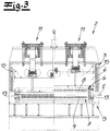
- the figures show a device for connecting metal strips, namely for connecting a band end of a first metal strip to the strip beginning of a second metal strip.
- a device is preferably integrated in a belt treatment plant (belt process line), for. B. in the inlet region of such a ribbon processing line.
- belt treatment plant belt process line
- There wound metal bands are handled in the inlet part, then go through various treatment stations and are wound up again in the outlet part or processed in any other way. So that the metal bands do not always have to be re-threaded, the beginning of the band of a new covenant is connected to the band end of the last covenant.
- the beginning of the tape and the end of the tape are positioned one above the other to form an overlap and connected to one another in the region of the overlap at a plurality of connection points.
- connection methods are known in principle.
- the metal bands are in the Fig. 1 to 5 not shown, only the band plane E is indicated.
- connection points are produced by means of clinching without cutting portion (clinching).
- the device has a connection press 2 with press frame 3, press upper part 4 and press lower part 5.
- the tape running direction B is in Fig. 4 indicated in Fig. 1 and 3 it is perpendicular to the drawing plane.
- an upper tool 6 is fastened with a plurality of punches 8 for clinching.
- a lower tool 7 is fixed with a plurality of dies for clinching.
- Upper tool 6 with punches 8 and lower tool 7 with 9 dies form a tool set 10a, b, c.
- Upper tool 6 and lower tool 7 are each formed as multiple tools, each with a plurality of punches distributed over the bandwidth 8 and 9 dies.
- the press upper part 4 for applying the pressing force with the drives 11 against the fixed press base 5 can be moved.
- the drives 11 are formed in the embodiments as a hydraulic press cylinder 11, which are connected with their pistons to the movable press upper part 4 and are supported on the fixed upper spar of the press frame 3.
- the Fig. 1 and 3 show the press 2 in a split representation each closed in one half and opened in the other half.
- the press upper part 4 is guided on guides 3 on the press frame 3.
- the illustrated embodiments are each equipped with a tool changing device 12, which provide several tool sets 10a, b, c, each consisting of upper tool 6 and lower tool 7, are available. With the aid of this tool changing device 12, the individual tool sets 10a, b, c can be converted from a working position within the press into a waiting position outside the press, and vice versa. In this way, it is possible to replace the tools and the device to the desired conditions, eg. B. adapt to the respective strip thickness. Because preferably different tools are used for connecting certain strip thicknesses.
- Fig. 1 and 2 on the one hand and the Fig. 3 to 5 On the other hand, show two embodiments with differently designed tool changing devices 12th
- a first embodiment in which the tools 6, 7 are transferred with the tool changing device 12 transversely to the strip running direction B from the working position to the waiting position.
- the tool changing device 12 is arranged laterally next to the press 2 in this embodiment. It has a shuttle table 14 with several along the strip running direction B successively arranged tool sets 10a, b, c. If the located in the connection press 2 tool are exchanged, it is transverse to the direction of tape B from the press out on the shuttle table 14 is pulled (or pushed). The shuttle table 14 then moves parallel to the direction of tape travel, z. B. a position, so then another tool can be pushed transversely to the strip running direction B in the press 2 (or pulled) can be.
- FIG. 2 It can be seen that in the illustrated embodiment, four different tools or tool sets 10a, b, c, 10 'are arranged in the tool changing device 12. Three tool sets 10a, b, c are provided for the clinching, with which one, two or three rows of connecting points can be set.
- the first tool 10a has a series of punches and dies
- the second tool set 10b has two rows of punches and dies arranged one behind the other in the direction of travel B
- the third tool set 10c has three rows of punches and dies arranged one behind the other in the direction of strip travel, so that optionally one, two or three rows of connecting points can be set with a single press stroke, depending on which tool 10a, b, c is arranged in the press 2.
- an additional tool set 10 ' is provided, which is designed as a punching tool 10', so that the press can also be easily converted for a punched connection. It becomes clear that z. B.
- different tool sets can be used, wherein the individual tool sets 10 a, b, c usually have different dot diameter or punch diameter.
- small dot diameters are usually used, in which case relatively many connection points are set.
- large dot diameters are used, with fewer dots usually being placed.
- upper tool 6 and lower tool 7 are connected to each other by forming the tool set 10a, b, c via guides 13.
- each tool set has a total of four guide columns 13 arranged at the corners. This applies equally to the embodiment according to Fig. 1 and 2 as for the embodiment Fig. 3 and 4 ,
- FIG. 3 to 5 a second embodiment in which the tool sets 10a, b, c and 10 'are moved along the strip running direction B for replacement.
- the individual tool sets are in turn arranged one after the other in the belt running direction B, but this time not offset laterally to the connecting press 2, but along the tape running direction offset to the connecting press 2. Nevertheless, the passage of the metal strip is not disturbed, since the upper tools 6 always above the metal strip or the band level E and the lower tools 7 are always arranged below the metal strip and since the guide columns 13 are always arranged outside the band area.
- the tool set can be replaced even when the tape is in the machine.
- Fig. 4 shows a view in which the punching tool 10 'is arranged in the machine by way of example.
- alternating drives are usually provided, for. B. hydraulic drives, which are not shown in detail in the figures.
- connection point rows arranged one behind the other in the strip running direction can also be generated at the same time. This makes it possible to produce the entire band connection even with multiple rows of connection points with a single press stroke.
- the connection press provides sufficient pressing forces with the hydraulic cylinders 11.
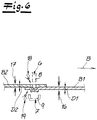
- Fig. 6 The principle of the clinch connection according to the invention is exemplary and simplified in Fig. 6 shown.
- the band end of the first metal strip B1 and the beginning of the strip of the second metal strip B2 and the overlap are shown, in the area with the clinching tool 6, 7, the connection points are set by clinching.
- a clinch connection without cutting share is shown.
- Fig. 6 It can be seen that with a first thickness measuring device 16, the thickness D1 of the strip end of the first metal strip B1 and a second thickness measuring device 17, the thickness D2 of the strip beginning of the second metal strip B2 are measured, before connecting the bands.
- These thickness measuring devices 16, 17 may, for. B. as optical thickness measuring devices, for. B. be formed by laser radiation.
- the thickness measuring devices 16 17, it is then possible to control and regulate the joining process as a function of the measured thickness or of the measured thicknesses D1, D2, with a control and / or regulating device (not illustrated).
- the thickness measuring devices are arranged in the immediate vicinity of the joining tools, they can be integrated into the joining device.
- the invention also includes embodiments in which the thickness measuring devices are arranged at a different position within the strip processing plant, so z. B. arranged a thickness measuring device immediately behind a decoiler be there to measure the thickness of the beginning of the tape, the corresponding signal or the corresponding value can then be processed in the course of the band connection.
- Fig. 6 options can be used individually or in combination, eg. B. in a device after Fig. 1 to 5 Alternatively, however, with differently designed devices.
Landscapes
- Engineering & Computer Science (AREA)
- Mechanical Engineering (AREA)
- Punching Or Piercing (AREA)
- Folding Of Thin Sheet-Like Materials, Special Discharging Devices, And Others (AREA)
- Replacement Of Web Rolls (AREA)
- Basic Packing Technique (AREA)
- Butt Welding And Welding Of Specific Article (AREA)
- Testing And Monitoring For Control Systems (AREA)
- Pressure Welding/Diffusion-Bonding (AREA)
Applications Claiming Priority (1)
| Application Number | Priority Date | Filing Date | Title |
|---|---|---|---|
| DE102014116713.9A DE102014116713A1 (de) | 2014-11-14 | 2014-11-14 | Verfahren zum Verbinden von Metallbändern |
Publications (2)
| Publication Number | Publication Date |
|---|---|
| EP3020488A1 EP3020488A1 (de) | 2016-05-18 |
| EP3020488B1 true EP3020488B1 (de) | 2018-03-14 |
Family
ID=53800861
Family Applications (1)
| Application Number | Title | Priority Date | Filing Date |
|---|---|---|---|
| EP15180134.7A Not-in-force EP3020488B1 (de) | 2014-11-14 | 2015-08-07 | Verfahren zum verbinden von metallbändern |
Country Status (10)
| Country | Link |
|---|---|
| US (1) | US20160136717A1 (pt) |
| EP (1) | EP3020488B1 (pt) |
| KR (1) | KR20160057975A (pt) |
| CN (1) | CN105598303B (pt) |
| BR (1) | BR102015028595A2 (pt) |
| DE (1) | DE102014116713A1 (pt) |
| ES (1) | ES2668347T3 (pt) |
| RU (1) | RU2690736C2 (pt) |
| TR (1) | TR201807642T4 (pt) |
| ZA (1) | ZA201508427B (pt) |
Families Citing this family (3)
| Publication number | Priority date | Publication date | Assignee | Title |
|---|---|---|---|---|
| US11233289B2 (en) | 2016-08-01 | 2022-01-25 | Cps Technology Holdings Llc | Weldable aluminum terminal pads of an electrochemical cell |
| WO2019146400A1 (ja) | 2018-01-24 | 2019-08-01 | 武延 本郷 | 固定装置、固定方法および構造体 |
| KR102048461B1 (ko) * | 2019-07-24 | 2019-11-25 | 주식회사 엘프시스템 | 연료전지용 분리판의 제조 설비 및 제조 방법 |
Family Cites Families (19)
| Publication number | Priority date | Publication date | Assignee | Title |
|---|---|---|---|---|
| DE3473422D1 (en) * | 1984-02-27 | 1988-09-22 | Kawasaki Steel Co | An apparatus for butt welding steel strips by using a laser beam in a steel strip-processing line |
| SU1490020A1 (ru) * | 1986-12-10 | 1989-06-30 | Предприятие П/Я Р-6491 | Устройство дл соединени концов металлической ленты |
| US5528815A (en) * | 1990-04-03 | 1996-06-25 | Webb; Edward L. T. | Clinching tool for sheet metal joining |
| JPH04309472A (ja) * | 1991-04-09 | 1992-11-02 | Nippon Steel Corp | 薄鋼帯の溶接接続方法 |
| FR2691388B1 (fr) * | 1992-05-21 | 1997-01-31 | Homax Ag | Nouveau point d'assemblage de flans de tole par fluage a froid et machine d'outils pour la realisation d'un tel point d'assemblage. |
| TW387569U (en) * | 1998-09-25 | 2000-04-11 | Advantech Co Ltd | Improvements of interface card panel for compact PCI system |
| DE19847794C1 (de) * | 1998-10-16 | 1999-08-19 | Eckold Ag | Vorrichtung zum mechanischen Fügen flächig aufeinanderliegender Bleche durch Umformen |
| DE10208304C1 (de) * | 2002-02-26 | 2003-11-20 | Fraunhofer Ges Forschung | Verfahren zur Überwachung und gegebenenfalls Steuerung des Fügeprozesses beim Durchsetzfügen |
| US20060096075A1 (en) * | 2004-11-08 | 2006-05-11 | Victor Robinson | Clinching tool, die and method for use thereof |
| DE102005037182A1 (de) | 2005-08-06 | 2007-02-15 | Bwg Bergwerk- Und Walzwerk-Maschinenbau Gmbh | Verfahren zum Abkleben einer Bandverbindung und Klebebandapplikator |
| US7856704B2 (en) * | 2005-10-14 | 2010-12-28 | Gm Global Technology Operations, Inc. | Monitoring system for clinching process |
| US20100083480A1 (en) * | 2008-10-06 | 2010-04-08 | Gm Global Technology Operations, Inc. | Method of Friction-Assisted Clinching |
| JP2010105024A (ja) * | 2008-10-31 | 2010-05-13 | Sumitomo Light Metal Ind Ltd | 金属板の積層体の製造方法及び該金属板の積層体の製造方法により製造される金属板の積層体 |
| DE102008063277A1 (de) | 2008-12-29 | 2010-07-08 | Bwg Bergwerk- Und Walzwerk-Maschinenbau Gmbh | Verfahren und Vorrichtung zum Verbinden von Metallbändern |
| EP2514538B1 (en) * | 2011-10-07 | 2018-05-30 | Aleris Aluminum Duffel BVBA | Method of joining aluminium alloy sheet |
| DE102012013829B4 (de) * | 2012-07-13 | 2024-03-14 | Newfrey Llc | Stanznietmatrize, Stanznietwerkzeug und Stanznietverfahren |
| DE102012108161B4 (de) * | 2012-09-03 | 2016-09-22 | Bwg Bergwerk- Und Walzwerk-Maschinenbau Gmbh | Verfahren und Vorrichtung zum Verbinden von Metallbändern |
| CN103212643B (zh) * | 2013-04-24 | 2015-04-08 | 莱芜钢铁集团有限公司 | 冷轧带钢用坯料无头酸洗的带头压合系统及其工作方法 |
| DE102014116710A1 (de) * | 2014-11-14 | 2016-05-19 | Bwg Bergwerk- Und Walzwerk-Maschinenbau Gmbh | Verfahren zum Verbinden von Metallbändern |
-
2014
- 2014-11-14 DE DE102014116713.9A patent/DE102014116713A1/de not_active Withdrawn
-
2015
- 2015-08-07 TR TR2018/07642T patent/TR201807642T4/tr unknown
- 2015-08-07 ES ES15180134.7T patent/ES2668347T3/es active Active
- 2015-08-07 EP EP15180134.7A patent/EP3020488B1/de not_active Not-in-force
- 2015-09-11 US US14/851,496 patent/US20160136717A1/en not_active Abandoned
- 2015-10-07 RU RU2015142784A patent/RU2690736C2/ru not_active IP Right Cessation
- 2015-10-20 KR KR1020150146247A patent/KR20160057975A/ko unknown
- 2015-11-13 ZA ZA2015/08427A patent/ZA201508427B/en unknown
- 2015-11-13 BR BR102015028595A patent/BR102015028595A2/pt not_active Application Discontinuation
- 2015-11-13 CN CN201510777405.0A patent/CN105598303B/zh not_active Expired - Fee Related
Non-Patent Citations (1)
| Title |
|---|
| None * |
Also Published As
| Publication number | Publication date |
|---|---|
| CN105598303B (zh) | 2019-08-20 |
| RU2690736C2 (ru) | 2019-06-05 |
| BR102015028595A2 (pt) | 2016-05-31 |
| EP3020488A1 (de) | 2016-05-18 |
| ES2668347T3 (es) | 2018-05-17 |
| RU2015142784A (ru) | 2017-04-10 |
| RU2015142784A3 (pt) | 2019-02-04 |
| ZA201508427B (en) | 2016-09-28 |
| DE102014116713A1 (de) | 2016-05-19 |
| CN105598303A (zh) | 2016-05-25 |
| US20160136717A1 (en) | 2016-05-19 |
| KR20160057975A (ko) | 2016-05-24 |
| TR201807642T4 (tr) | 2018-06-21 |
Similar Documents
| Publication | Publication Date | Title |
|---|---|---|
| EP3020489B1 (de) | Verfahren und bandbehandlungsanlage zum verbinden von metallbändern | |
| DE102012108161B4 (de) | Verfahren und Vorrichtung zum Verbinden von Metallbändern | |
| EP2806986B1 (de) | Verfahren und vorrichtung zum verbinden zweier enden metallischer bänder | |
| WO2012156347A2 (de) | VORRICHTUNG UND VERFAHREN ZUM HERSTELLEN EINES MAßGESCHNEIDERTEN BLECHBANDES ODER METALLPROFILS | |
| DE102011050001A1 (de) | Verfahren und Vorrichtung zur Herstellung von flanschlosen Ziehteilen | |
| EP1688195A1 (de) | Rollenwerkzeug zur linienhaften Blechverformung sowie Blechverformungsvorrichtung mit einem derartigen Rollenwerkzeug | |
| EP3020488B1 (de) | Verfahren zum verbinden von metallbändern | |
| DE19634723C2 (de) | Verfahren zum Herstellen und Schichten von Bauteilen, sowie eine Vorrichtung dafür | |
| WO2014114541A1 (de) | Vorrichtung zum verbinden von aufeinanderfolgend in eine bandbehandlungsanlage einlaufenden metallflachprodukten | |
| DE2361078A1 (de) | Verfahren zum praegen von metallbaendern und einrichtung zur durchfuehrung des verfahrens | |
| EP3034191B1 (de) | Vorrichtung und Verfahren zur Herstellung eines länglichen Profilteils | |
| DE102010033191B4 (de) | Vorrichtung zum Schneiden von hochfesten Werkstücken | |
| DE102006045485B4 (de) | Vorrichtung zum Verbinden der Enden zweier Bänder | |
| DE102006041494B3 (de) | Verfahren und Vorrichtung zur Herstellung eines Gleitlagerelementes | |
| DE2724886C3 (de) | Verfahren und Vorrichtung zum Herstellen von schalenartigen Werkstücken | |
| DE102012220817B3 (de) | Vorschubeinrichtung zur translatorischen Bewegung eines bandförmigen Werkstücks, sowie Verfahren und Verwendung dazu | |
| DE102004051454B4 (de) | Verfahren und Vorrichtung zur Herstellung eines Profils | |
| DE2434217A1 (de) | Verfahren zum formen eines bogenfoermigen steges fuer eine bremsbacke und vorrichtung zur durchfuehrung des verfahrens | |
| DE2750742A1 (de) | Querteilanlage zum zerschneiden von bandmaterial | |
| DE102019110132A1 (de) | Begrenzungselement für Rasen; Vorrichtung und Verfahren zur Herstellung eines solchen Begrenzungselements | |
| DE1925845C3 (de) | Vorrichtung zum klebenden Verbinden von Metallbändern | |
| DE1194810B (de) | Vorrichtung zur Herstellung von Blechzylindern, vorzugsweise fuer die Ummantelung von Rohrisolierungen | |
| DE102014018543A1 (de) | Verfahren zur Herstellung von Rohren | |
| DE202012004801U1 (de) | Vorrichtung zum Verbinden zweier Enden metallischer Bänder | |
| DE2457565B2 (de) | Einrichtung zur spanabhebenden kantenbearbeitung von schnellaufendem bandmaterial |
Legal Events
| Date | Code | Title | Description |
|---|---|---|---|
| PUAI | Public reference made under article 153(3) epc to a published international application that has entered the european phase |
Free format text: ORIGINAL CODE: 0009012 |
|
| AK | Designated contracting states |
Kind code of ref document: A1 Designated state(s): AL AT BE BG CH CY CZ DE DK EE ES FI FR GB GR HR HU IE IS IT LI LT LU LV MC MK MT NL NO PL PT RO RS SE SI SK SM TR |
|
| AX | Request for extension of the european patent |
Extension state: BA ME |
|
| 17P | Request for examination filed |
Effective date: 20160610 |
|
| RBV | Designated contracting states (corrected) |
Designated state(s): AL AT BE BG CH CY CZ DE DK EE ES FI FR GB GR HR HU IE IS IT LI LT LU LV MC MK MT NL NO PL PT RO RS SE SI SK SM TR |
|
| GRAP | Despatch of communication of intention to grant a patent |
Free format text: ORIGINAL CODE: EPIDOSNIGR1 |
|
| INTG | Intention to grant announced |
Effective date: 20171030 |
|
| GRAS | Grant fee paid |
Free format text: ORIGINAL CODE: EPIDOSNIGR3 |
|
| GRAA | (expected) grant |
Free format text: ORIGINAL CODE: 0009210 |
|
| AK | Designated contracting states |
Kind code of ref document: B1 Designated state(s): AL AT BE BG CH CY CZ DE DK EE ES FI FR GB GR HR HU IE IS IT LI LT LU LV MC MK MT NL NO PL PT RO RS SE SI SK SM TR |
|
| REG | Reference to a national code |
Ref country code: GB Ref legal event code: FG4D Free format text: NOT ENGLISH |
|
| REG | Reference to a national code |
Ref country code: CH Ref legal event code: EP Ref country code: AT Ref legal event code: REF Ref document number: 978347 Country of ref document: AT Kind code of ref document: T Effective date: 20180315 |
|
| REG | Reference to a national code |
Ref country code: IE Ref legal event code: FG4D Free format text: LANGUAGE OF EP DOCUMENT: GERMAN |
|
| REG | Reference to a national code |
Ref country code: DE Ref legal event code: R096 Ref document number: 502015003356 Country of ref document: DE |
|
| REG | Reference to a national code |
Ref country code: SE Ref legal event code: TRGR |
|
| REG | Reference to a national code |
Ref country code: ES Ref legal event code: FG2A Ref document number: 2668347 Country of ref document: ES Kind code of ref document: T3 Effective date: 20180517 |
|
| REG | Reference to a national code |
Ref country code: NL Ref legal event code: FP |
|
| REG | Reference to a national code |
Ref country code: LT Ref legal event code: MG4D |
|
| PG25 | Lapsed in a contracting state [announced via postgrant information from national office to epo] |
Ref country code: LT Free format text: LAPSE BECAUSE OF FAILURE TO SUBMIT A TRANSLATION OF THE DESCRIPTION OR TO PAY THE FEE WITHIN THE PRESCRIBED TIME-LIMIT Effective date: 20180314 Ref country code: CY Free format text: LAPSE BECAUSE OF FAILURE TO SUBMIT A TRANSLATION OF THE DESCRIPTION OR TO PAY THE FEE WITHIN THE PRESCRIBED TIME-LIMIT Effective date: 20180314 Ref country code: FI Free format text: LAPSE BECAUSE OF FAILURE TO SUBMIT A TRANSLATION OF THE DESCRIPTION OR TO PAY THE FEE WITHIN THE PRESCRIBED TIME-LIMIT Effective date: 20180314 Ref country code: NO Free format text: LAPSE BECAUSE OF FAILURE TO SUBMIT A TRANSLATION OF THE DESCRIPTION OR TO PAY THE FEE WITHIN THE PRESCRIBED TIME-LIMIT Effective date: 20180614 Ref country code: HR Free format text: LAPSE BECAUSE OF FAILURE TO SUBMIT A TRANSLATION OF THE DESCRIPTION OR TO PAY THE FEE WITHIN THE PRESCRIBED TIME-LIMIT Effective date: 20180314 |
|
| REG | Reference to a national code |
Ref country code: FR Ref legal event code: PLFP Year of fee payment: 4 |
|
| PG25 | Lapsed in a contracting state [announced via postgrant information from national office to epo] |
Ref country code: RS Free format text: LAPSE BECAUSE OF FAILURE TO SUBMIT A TRANSLATION OF THE DESCRIPTION OR TO PAY THE FEE WITHIN THE PRESCRIBED TIME-LIMIT Effective date: 20180314 Ref country code: LV Free format text: LAPSE BECAUSE OF FAILURE TO SUBMIT A TRANSLATION OF THE DESCRIPTION OR TO PAY THE FEE WITHIN THE PRESCRIBED TIME-LIMIT Effective date: 20180314 Ref country code: BG Free format text: LAPSE BECAUSE OF FAILURE TO SUBMIT A TRANSLATION OF THE DESCRIPTION OR TO PAY THE FEE WITHIN THE PRESCRIBED TIME-LIMIT Effective date: 20180614 |
|
| PG25 | Lapsed in a contracting state [announced via postgrant information from national office to epo] |
Ref country code: MT Free format text: LAPSE BECAUSE OF FAILURE TO SUBMIT A TRANSLATION OF THE DESCRIPTION OR TO PAY THE FEE WITHIN THE PRESCRIBED TIME-LIMIT Effective date: 20180314 |
|
| PG25 | Lapsed in a contracting state [announced via postgrant information from national office to epo] |
Ref country code: PL Free format text: LAPSE BECAUSE OF FAILURE TO SUBMIT A TRANSLATION OF THE DESCRIPTION OR TO PAY THE FEE WITHIN THE PRESCRIBED TIME-LIMIT Effective date: 20180314 Ref country code: AL Free format text: LAPSE BECAUSE OF FAILURE TO SUBMIT A TRANSLATION OF THE DESCRIPTION OR TO PAY THE FEE WITHIN THE PRESCRIBED TIME-LIMIT Effective date: 20180314 Ref country code: EE Free format text: LAPSE BECAUSE OF FAILURE TO SUBMIT A TRANSLATION OF THE DESCRIPTION OR TO PAY THE FEE WITHIN THE PRESCRIBED TIME-LIMIT Effective date: 20180314 Ref country code: RO Free format text: LAPSE BECAUSE OF FAILURE TO SUBMIT A TRANSLATION OF THE DESCRIPTION OR TO PAY THE FEE WITHIN THE PRESCRIBED TIME-LIMIT Effective date: 20180314 |
|
| REG | Reference to a national code |
Ref country code: GR Ref legal event code: EP Ref document number: 20180401216 Country of ref document: GR Effective date: 20181012 |
|
| PG25 | Lapsed in a contracting state [announced via postgrant information from national office to epo] |
Ref country code: SK Free format text: LAPSE BECAUSE OF FAILURE TO SUBMIT A TRANSLATION OF THE DESCRIPTION OR TO PAY THE FEE WITHIN THE PRESCRIBED TIME-LIMIT Effective date: 20180314 Ref country code: CZ Free format text: LAPSE BECAUSE OF FAILURE TO SUBMIT A TRANSLATION OF THE DESCRIPTION OR TO PAY THE FEE WITHIN THE PRESCRIBED TIME-LIMIT Effective date: 20180314 Ref country code: SM Free format text: LAPSE BECAUSE OF FAILURE TO SUBMIT A TRANSLATION OF THE DESCRIPTION OR TO PAY THE FEE WITHIN THE PRESCRIBED TIME-LIMIT Effective date: 20180314 |
|
| PGFP | Annual fee paid to national office [announced via postgrant information from national office to epo] |
Ref country code: IT Payment date: 20180919 Year of fee payment: 16 |
|
| REG | Reference to a national code |
Ref country code: DE Ref legal event code: R097 Ref document number: 502015003356 Country of ref document: DE |
|
| PG25 | Lapsed in a contracting state [announced via postgrant information from national office to epo] |
Ref country code: PT Free format text: LAPSE BECAUSE OF FAILURE TO SUBMIT A TRANSLATION OF THE DESCRIPTION OR TO PAY THE FEE WITHIN THE PRESCRIBED TIME-LIMIT Effective date: 20180716 |
|
| PLBE | No opposition filed within time limit |
Free format text: ORIGINAL CODE: 0009261 |
|
| STAA | Information on the status of an ep patent application or granted ep patent |
Free format text: STATUS: NO OPPOSITION FILED WITHIN TIME LIMIT |
|
| PG25 | Lapsed in a contracting state [announced via postgrant information from national office to epo] |
Ref country code: DK Free format text: LAPSE BECAUSE OF FAILURE TO SUBMIT A TRANSLATION OF THE DESCRIPTION OR TO PAY THE FEE WITHIN THE PRESCRIBED TIME-LIMIT Effective date: 20180314 |
|
| 26N | No opposition filed |
Effective date: 20181217 |
|
| PG25 | Lapsed in a contracting state [announced via postgrant information from national office to epo] |
Ref country code: SI Free format text: LAPSE BECAUSE OF FAILURE TO SUBMIT A TRANSLATION OF THE DESCRIPTION OR TO PAY THE FEE WITHIN THE PRESCRIBED TIME-LIMIT Effective date: 20180314 |
|
| PG25 | Lapsed in a contracting state [announced via postgrant information from national office to epo] |
Ref country code: MC Free format text: LAPSE BECAUSE OF FAILURE TO SUBMIT A TRANSLATION OF THE DESCRIPTION OR TO PAY THE FEE WITHIN THE PRESCRIBED TIME-LIMIT Effective date: 20180314 |
|
| REG | Reference to a national code |
Ref country code: CH Ref legal event code: PL |
|
| PG25 | Lapsed in a contracting state [announced via postgrant information from national office to epo] |
Ref country code: LI Free format text: LAPSE BECAUSE OF NON-PAYMENT OF DUE FEES Effective date: 20180831 Ref country code: LU Free format text: LAPSE BECAUSE OF NON-PAYMENT OF DUE FEES Effective date: 20180807 Ref country code: CH Free format text: LAPSE BECAUSE OF NON-PAYMENT OF DUE FEES Effective date: 20180831 |
|
| REG | Reference to a national code |
Ref country code: IE Ref legal event code: MM4A |
|
| PG25 | Lapsed in a contracting state [announced via postgrant information from national office to epo] |
Ref country code: IE Free format text: LAPSE BECAUSE OF NON-PAYMENT OF DUE FEES Effective date: 20180807 |
|
| PGFP | Annual fee paid to national office [announced via postgrant information from national office to epo] |
Ref country code: NL Payment date: 20190821 Year of fee payment: 5 |
|
| PGFP | Annual fee paid to national office [announced via postgrant information from national office to epo] |
Ref country code: FR Payment date: 20190822 Year of fee payment: 5 Ref country code: ES Payment date: 20190924 Year of fee payment: 5 Ref country code: SE Payment date: 20190821 Year of fee payment: 5 Ref country code: DE Payment date: 20190802 Year of fee payment: 5 Ref country code: TR Payment date: 20190731 Year of fee payment: 5 |
|
| PGFP | Annual fee paid to national office [announced via postgrant information from national office to epo] |
Ref country code: BE Payment date: 20190821 Year of fee payment: 5 |
|
| PGFP | Annual fee paid to national office [announced via postgrant information from national office to epo] |
Ref country code: GB Payment date: 20190821 Year of fee payment: 5 |
|
| PG25 | Lapsed in a contracting state [announced via postgrant information from national office to epo] |
Ref country code: GR Free format text: LAPSE BECAUSE OF NON-PAYMENT OF DUE FEES Effective date: 20200305 |
|
| PG25 | Lapsed in a contracting state [announced via postgrant information from national office to epo] |
Ref country code: HU Free format text: LAPSE BECAUSE OF FAILURE TO SUBMIT A TRANSLATION OF THE DESCRIPTION OR TO PAY THE FEE WITHIN THE PRESCRIBED TIME-LIMIT; INVALID AB INITIO Effective date: 20150807 Ref country code: MK Free format text: LAPSE BECAUSE OF NON-PAYMENT OF DUE FEES Effective date: 20180314 |
|
| PG25 | Lapsed in a contracting state [announced via postgrant information from national office to epo] |
Ref country code: IS Free format text: LAPSE BECAUSE OF FAILURE TO SUBMIT A TRANSLATION OF THE DESCRIPTION OR TO PAY THE FEE WITHIN THE PRESCRIBED TIME-LIMIT Effective date: 20180714 |
|
| REG | Reference to a national code |
Ref country code: DE Ref legal event code: R119 Ref document number: 502015003356 Country of ref document: DE |
|
| REG | Reference to a national code |
Ref country code: SE Ref legal event code: EUG |
|
| REG | Reference to a national code |
Ref country code: NL Ref legal event code: MM Effective date: 20200901 |
|
| GBPC | Gb: european patent ceased through non-payment of renewal fee |
Effective date: 20200807 |
|
| REG | Reference to a national code |
Ref country code: BE Ref legal event code: MM Effective date: 20200831 |
|
| PG25 | Lapsed in a contracting state [announced via postgrant information from national office to epo] |
Ref country code: SE Free format text: LAPSE BECAUSE OF NON-PAYMENT OF DUE FEES Effective date: 20200808 |
|
| PG25 | Lapsed in a contracting state [announced via postgrant information from national office to epo] |
Ref country code: IT Free format text: LAPSE BECAUSE OF NON-PAYMENT OF DUE FEES Effective date: 20200807 Ref country code: FR Free format text: LAPSE BECAUSE OF NON-PAYMENT OF DUE FEES Effective date: 20200831 Ref country code: DE Free format text: LAPSE BECAUSE OF NON-PAYMENT OF DUE FEES Effective date: 20210302 |
|
| PG25 | Lapsed in a contracting state [announced via postgrant information from national office to epo] |
Ref country code: GB Free format text: LAPSE BECAUSE OF NON-PAYMENT OF DUE FEES Effective date: 20200807 Ref country code: BE Free format text: LAPSE BECAUSE OF NON-PAYMENT OF DUE FEES Effective date: 20200831 |
|
| REG | Reference to a national code |
Ref country code: AT Ref legal event code: MM01 Ref document number: 978347 Country of ref document: AT Kind code of ref document: T Effective date: 20200807 |
|
| PG25 | Lapsed in a contracting state [announced via postgrant information from national office to epo] |
Ref country code: NL Free format text: LAPSE BECAUSE OF NON-PAYMENT OF DUE FEES Effective date: 20200901 Ref country code: AT Free format text: LAPSE BECAUSE OF NON-PAYMENT OF DUE FEES Effective date: 20200807 |
|
| REG | Reference to a national code |
Ref country code: ES Ref legal event code: FD2A Effective date: 20211230 |
|
| PG25 | Lapsed in a contracting state [announced via postgrant information from national office to epo] |
Ref country code: ES Free format text: LAPSE BECAUSE OF NON-PAYMENT OF DUE FEES Effective date: 20200808 |
|
| PG25 | Lapsed in a contracting state [announced via postgrant information from national office to epo] |
Ref country code: TR Free format text: LAPSE BECAUSE OF NON-PAYMENT OF DUE FEES Effective date: 20200807 |