EP3017686A1 - Schneidkopf, insbesondere für eine baumschere - Google Patents
Schneidkopf, insbesondere für eine baumschere Download PDFInfo
- Publication number
- EP3017686A1 EP3017686A1 EP15002765.4A EP15002765A EP3017686A1 EP 3017686 A1 EP3017686 A1 EP 3017686A1 EP 15002765 A EP15002765 A EP 15002765A EP 3017686 A1 EP3017686 A1 EP 3017686A1
- Authority
- EP
- European Patent Office
- Prior art keywords
- cutting head
- housing
- connecting element
- knife
- handle
- Prior art date
- Legal status (The legal status is an assumption and is not a legal conclusion. Google has not performed a legal analysis and makes no representation as to the accuracy of the status listed.)
- Granted
Links
Images






Classifications
-
- A—HUMAN NECESSITIES
- A01—AGRICULTURE; FORESTRY; ANIMAL HUSBANDRY; HUNTING; TRAPPING; FISHING
- A01G—HORTICULTURE; CULTIVATION OF VEGETABLES, FLOWERS, RICE, FRUIT, VINES, HOPS OR SEAWEED; FORESTRY; WATERING
- A01G3/00—Cutting implements specially adapted for horticultural purposes; Delimbing standing trees
- A01G3/02—Secateurs; Flower or fruit shears
- A01G3/025—Secateurs; Flower or fruit shears having elongated or extended handles
- A01G3/0255—Tree pruners, i.e. pruning shears carried at the end of a pole
Definitions
- the invention relates to a cutting head, in particular for a pruning shears, the type mentioned in the preamble of claim 1.
- Such cutting heads are known in many forms and usually attached to the end of a handle handle considerable length, which may optionally be formed telescopically.
- a cutting head of the type mentioned in the preamble of claim 1 which has a hollow flat housing which is formed by two housing halves.
- a housing half simultaneously forms a counter-blade, and a movable blade is pivotally mounted about a pivot shaft in the two housing halves.
- the movable knife has a lever arm whose free end is connected to drive means, for example a cable, which extends through a stem connection and the stem to the lower end of the stem and is led out of these via a slot.
- This cutting head has a considerable weight, since due to the design of the one half of the housing as a counter cutting this housing half must be made of metal, and there are significant actuation forces on the drive means required if, for example, branches are to be cut with a larger diameter.
- a gear in the form of a two-part chain disc is attached to an extension of the stem forming base plate, which simultaneously forms the counter blade and the movable blade pivotally supports, a the first part of smaller diameter, which is at least partially looped by a chain which is attached at its one end to this smaller part of the double chain plate, while its other end is fixed to the movable blade to the rotation of the chain plate, the knife in To drive towards the counterknife.
- the greater part of the double chain pulley is wrapped by a second chain which is attached to the larger part of the double chain pulley and the other end is connected via a pulley and a pulley with an operating cable. Since the second part of the double chain disc has a considerable distance from the base plate, the base plate must be relatively solid in order to prevent deformation during actuation of the cable. Furthermore, this cutting head has a considerable thickness transversely to the plane of the knife or the counter-blade, which is undesirable in particular in very densely overgrown trees or bushes. In addition, there is a relatively high weight of the cutting head, which is disturbing when this cutting head is located at the end of a relatively long handle.
- the operation of a cable for moving the movable knife toward the counter-blade by a slidably mounted on the handle sliding sleeve can be formed, which has slots through which in the interior of the hollow handle extending lugs, which are connected to a connector, where the free end of a confirmation rope is attached.
- the invention has for its object to provide a cutting head of the type mentioned, which has a high efficiency in the operation with a lightweight design and cost-effective design and yet has a closed design to catch the cutting head in the branches and contamination of the Mechanism of the cutting head to avoid.
- all parts of the mechanism including the movable blade driving mechanism, are arranged in a closed housing from which only the counter-blade protrudes from the cutting area of the movable blade.
- the drive means include a gear formed of two coaxially interconnected part gears of different diameters, the first part having a smaller diameter than the second part preferably being disposed in the plane of the blade and at least partially looped around by a first connecting element that this first part is connected to a lever arm of the knife.
- the second part of the gear wheel which has a larger diameter, is at least partially looped around by a second connecting element which extends towards the handle and through it to form an actuating element.
- This larger diameter portion of the gear is disposed substantially in the plane of the bedknife which is mounted on the inside of the housing. In this way, the thickness of the cutting head is reduced to a value which substantially corresponds to the thickness of the knife and the counter-blade.
- the housing halves may be made of a relatively small thickness and correspondingly low-weight plastic material and contribute only insignificantly to the width of the cutting head.
- This cutting head may, according to a preferred embodiment, be pivotally connected about a pivot shaft to a stem connection connected to the stem, the pivot shaft extending substantially at a right angle to the longitudinal axis of the stem.
- the outgoing from the one larger diameter part of the gear tray connecting element is guided over a pulley, which is arranged such that the longitudinal axis of extending from the second part of the gear to the deflection roller length range of the second Connecting element is arranged substantially coaxially to the central axis of the pivot shaft. In this way, a change in the opening angle of the movable blade is prevented in a pivoting of the cutting head relative to the handle.
- the first connecting element may extend from the gear wheel in the direction of the lever arm of the knife such that the angle between the longitudinal axis of this second connecting element and a line extending the pivot axis of the knife with the articulation point of the second connecting element as the knife closes increasingly a right Angle approaches, so that the force exerted on the lever arm is increasingly increased when closing.
- the first and second connecting elements may be formed by a chain, a rope, a band or the like, wherein according to a preferred embodiment it is provided that the first connecting element is formed by a chain and the second connecting element by a cable to the weight of the cutting head so far as possible decrease.
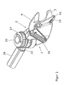
- FIG. 1 is an overall perspective view of the cutting head shown having a housing consisting of two housing halves 1, 2, in which a counter-blade 3 and a knife 6 are arranged, which is pivotable about a pivot axis 8.
- the entire pivot head is pivotally connected via a handle connection 21, 22 with a handle 26 to pivot the cutting head relative to the stem in the particular of the FIGS. 4 and 5 to allow a recognizable manner.
- the pivoting of the cutting head can be pivoted relative to the handle 26 after releasing a handwheel 27 or be aligned with a position aligned with the handle.
- the knife 6 is biased by a return spring 35 in a rest position and is transferred via a chain 10 and a lever arm 61 via a yet to be explained drive mechanism in the closed position.
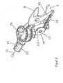
- the pivot axis 25 extends under a cap 30 through the stem connection and the housing through, as in particular FIG. 2 it can be seen, In FIG. 2 is the right half 1 of the housing and the handwheel is removed to show more details of the cutting head.
- FIG. 2 there is also the stem connection of two halves 21, 22 which are interconnected and connected via the pivot shaft 25 with the housing of the cutting head.
- FIG. 3 essentially corresponds to the FIG. 2 However, wherein the pivoting of the cutting head relative to the stem connection and thus the stem is shown.
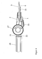
- FIGS. 4 and 5 show the position of the cutting head in an aligned with the handle 26 position or in a maximum pivoted position in which the cutting head can be hooked from above in the branch to be cut, to facilitate the cutting.
- FIG. 6 is a view of the housing of the cutting head with the right and left halves 1, 2, wherein it can be seen that these two halves are connected at their lower end via a snap-in connection 44 and are otherwise connected by screws. Furthermore, the housing has its in FIG. 6 upper end annular bearing elements 33, 45 which have bores 47 for receiving a screw 25 which forms the pivot axis for the pivoting of the cutting head relative to the handle connection.
- the underside of the upper ring member 33 is provided with locking projections 47 which cooperate with locking recesses in the handle connection 21, 22 to be described later, in order to secure the tightening of the hand wheel 27 a secure locking of the cutting head relative to the handle in a predetermined cutting position.
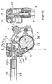
- FIGS. 7 and 8th show longitudinal and cross-sectional views through the cutting head in the chain plane or in the rope level.
- a gear wheel 11 is rotatably mounted about a rotational axis 14.
- the gear wheel has a first part 111 and a second part 112, which is preferably arranged coaxially with the first part 111 and has a larger diameter than the first part 111.
- the first part 111 is at least partially looped around by a first connecting element in the form of a chain 10 and fastened at 63 to the first part 111.
- the Chain 10 extends from the gear 11 to the free end of a lever arm 61 of the knife 6, which is pivotable about a shaft 7, 8.
- a second connecting element forming a cable 15 is fixed with a fastening point forming conventional nipple 62 in a recess on the circumference of the second part 112 of the gear 11 and extends around the second part 112 around to a guide roller 23, which in the interior of the stem connection 21, 22 is mounted via a shaft 24, as this particular FIG. 8 can be seen. From the guide roller 23 and through the interior of the handle connection 21, 22 and the handle 26, the cable 16 extends to not shown actuating means for the knife. 6
- FIG. 7 further shows that the rear end of the counter-blade 3 has an outline adapted to the shape and size of the second part 112 of the gear wheel 11, so that this second part 112 can be arranged at least substantially in the plane of the counter-blade 3, while the first part 111 of FIG Gear 11 in the plane of the movable blade 6 is located.
- the second part 112 of the gear can lie completely in the plane of the counter-blade 3.
- pivot shaft 25 can be seen, which connects the handle connection 21, 22 with the housing 1, 2 of the cutting head.
- the pivot shaft is in the form of a screw 25, onto which a nut 29 fastened in the handwheel is screwed, which makes it possible to fix the cutting head in relation to the handle 26 in a predetermined angular position.
- this pivot shaft or connecting screw 25 is aligned with the longitudinal axis of extending between the part 112 of the gear 11 and the guide roller 23 length portion of the cable 15, so that pivoting of the cutting head relative to the handle 26 does not lead to a change of Closed position of the knife leads.
- the rotation guide of the stem connection 21, 22 on the housing of the cutting head via an annular tongue and groove joint 20.
- FIG. 9 the two housing halves 1 and 2 are shown separately with the counter-blade 3 and the hand wheel 27, wherein it can be seen that the handwheel 27 to the in FIG. 8 shown pivot shaft 25 is rotatably mounted, wherein in the FIGS. 7 and 8th shown nut 29 forms the axial limit for the handwheel.
- the hand wheel is provided with two spiral surfaces 18 which slide on respective spiral surfaces 17 of the housing halves 1 and 2.
- the rotational movement of the handwheel 27 is controlled by a cam 40 and the stops 41 FIG. 9 limited.
- the handwheel 27 For loosening and tightening the handwheel 27 is sufficient so that about half a turn of the handwheel.
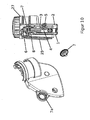
- FIG. 10 lets in connection with FIG. 11 recognize the attachment of the counter-blade 3 by means of a screw 4 and a slotted nut 5 on the left half of the housing 2.
- the nut 8 and the locking screw 7 form the hinge for the rotatably mounted on the counter blade knife 6.
- the FIG. 11 recognizable flat teeth on the locking screw 7 engages in corresponding recesses 7a on the outside of the left housing half 2 a.
- the nut 8 preferably has a shank with a first section extending through the knife 6 and a second section deviating from a round shape, which extends through a corresponding non-circular bore in the Countersink extends and is fixed in rotation therewith.
- the nut 8 and the locking screw 7 provide a further definition of the counter-blade 3 on the left housing half. 2
- the described embodiment of the cutting head allows even with a pivotable attachment of the cutting head to the stem a very simple installation, since the two halves 21, 22 of the stem connection with the pivot shaft 25, the guide roller 23 and the associated connecting element 15 according to the FIGS. 12 and 13 can be pre-assembled, wherein by a part-circular rib 34 according to FIG. 14 the jumping out of the connecting element 15 from the guide groove of the guide roller 23 is prevented.
- This first assembly can then as well as the remaining essential functional elements, such as counter blade 3, knife 6, gear 11 and connecting element 10 in the one, left in the described embodiment, housing half 2 are mounted and fixed, wherein the lying in this housing half end of Connecting element 15 with the customary in cables attachment nipple 62 placed around the gear 11 around and the nipple is inserted into the corresponding recess on the circumference of the larger diameter portion 112 of the gear 11.
- FIG. 11 the individual parts described above are shown separately again to see their design and interaction closer.
Landscapes
- Life Sciences & Earth Sciences (AREA)
- Biodiversity & Conservation Biology (AREA)
- Ecology (AREA)
- Forests & Forestry (AREA)
- Environmental Sciences (AREA)
- Scissors And Nippers (AREA)
- Harvester Elements (AREA)
- Knives (AREA)
Abstract
Description
- Die Erfindung bezieht sich auf einen Schneidkopf, insbesondere für eine Baumschere, der im Oberbegriff des Anspruchs 1 genannten Art.
- Derartige Schneidköpfe sind in vielfältigen Formen bekannt und zumeist am Ende eines Handhabungs-Stiels erheblicher Länge befestigt, der gegebenenfalls teleskopartig ausgebildet sein kann.
- Aus der
DE 615 201 ist ein Schneidkopf der im Oberbegriff des Anspruchs 1 genannten Art bekannt, der ein hohles flaches Gehäuse aufweist, das durch zwei Gehäusehälften gebildet ist. Eine Gehäusehälfte bildet gleichzeitig eine Gegenschneide, und ein bewegliches Messer ist um eine Schwenkwelle in den beiden Gehäusehälften schwenkbar gelagert. Das bewegliche Messer weist einen Hebelarm auf, dessen freies Ende mit Antriebseinrichtungen, beispielsweise einem Seilzug, verbunden ist, der sich durch einen Stiel-Anschluss und den Stiel zum unteren Ende des Stiels erstreckt und aus diesen über einen Schlitz herausgeführt ist. Dieser Schneidkopf weist ein erhebliches Gewicht auf, da aufgrund der Ausgestaltung der einen Gehäusehälfte als Gegenschneide diese Gehäusehälfte aus Metall hergestellt sein muss, und es sind erhebliche Betätigungskräfte an den Antriebseinrichtungen erforderlich, wenn beispielsweise Äste mit einem größeren Durchmesser geschnitten werden sollen. - Um diese hohen Betätigungskräfte, insbesondere gegen Ende des Schnittes, zu verringern, ist es beispielsweise aus der
DE 816 616 bekannt, den Seilzug an dem Hebelarm des beweglichen Messers so anzuordnen, das der Seilzug im Wesentlichen senkrecht zur Achse des Hebelarms angreift und sich einem rechten Winkel immer mehr nähert, je mehr die Schere in ihre Schließstellung gelangt. - Weiterhin ist es beispielsweise aus der
US 1507225 bekannt, Übersetzungsgetriebe für die Betätigung des beweglichen Messers in dem Schneidkopf anzuordnen. Zu diesem Zweck ist auf einer die Verlängerung des Stiels bildenden Grundplatte, die gleichzeitig die Gegenschneide bildet und das bewegliche Messer schwenkbar lagert, ein Getrieberad in Form einer zweiteiligen Kettenscheibe befestigt, die einen ersten Teil mit kleinerem Durchmesser aufweist, der zumindest teilweise von einer Kette umschlungen ist, die an ihrem einen Ende an diesem kleineren Teil der Doppelkettenscheibe befestigt ist, während ihr anderes Ende an dem beweglichen Messer befestigt ist, um bei einer Drehung der Kettenscheibe das Messer in Richtung auf die Gegenschneide anzutreiben. Der größere Teil der Doppelkettenscheibe ist von einer zweiten Kette umschlungen, die an dem größeren Teil der Doppelkettenscheibe befestigt ist und deren anderes Ende über eine Seilrolle und einen Flaschenzug mit einem Betätigungsseil verbunden ist. Da der zweite Teil der Doppelkettenscheibe einen erheblichen Abstand von der Grundplatte aufweist, muss die Grundplatte relativ massiv ausgebildet sein, um eine Verformung bei einer Betätigung des Seilzuges zu verhindern. Weiterhin weist dieser Schneidkopf eine erhebliche Dicke quer zur Ebene des Messers beziehungsweise der Gegenschneide auf, was insbesondere bei sehr dicht bewachsenen Bäumen oder Büschen unerwünscht ist. Außerdem ergibt sich ein relativ hohes Gewicht des Schneidkopfes, was störend ist, wenn dieser Schneidkopf am Ende eines relativ langen Stiels angeordnet ist. - Wie dies in der
DE 3330093 gezeigt ist, kann die Betätigung eines Seilzuges zum Bewegen des beweglichen Messers in Richtung auf die Gegenschneide durch eine an dem Stiel verschiebbar befestigte Schiebehülse gebildet werden, die sich durch Schlitze in das Innere des hohlen Stiels erstreckende Ansätze aufweist, die mit einem Verbindungsstück verbunden sind, an dem das freie Ende eines Bestätigungsseils befestigt ist. - Um einen Zugang auch an schwieriger zu erreichende Stellen in den Ästen eines Baumes zu erreichen, ist es weiterhin aus der
EP 0485518 B1 bekannt, den Schneidkopf an dem oberen Ende des Stiels nicht starr sondern verschwenkbar zu befestigten, wodurch die Probleme eines hohen Gewichtes und der Betätigungskräfte weiter vergrößert werden. - Der Erfindung liegt die Aufgabe zugrunde, einen Schneidkopf der eingangs genannten Art zu schaffen, der bei einer leichten Bauweise und kostengünstigen Konstruktion einen hohen Wirkungsgrad bei der Betätigung aufweist und dennoch eine geschlossene Bauweise aufweist, um ein Verfangen des Schneidkopfes in dem Astwerk und eine Verschmutzung des Mechanismus des Schneidkopfes zu vermeiden.
- Diese Aufgabe wird durch die im Patentanspruch 1 angegebenen Merkmale gelöst.
- Vorteilhafter Ausgestaltungen und Weiterbildungen der Erfindung ergeben sich aus den Unteransprüchen.
- Bei dem erfindungsgemäßen Schneidkopf sind sämtliche Teile des Mechanismus einschließlich des Antriebsmechanismus für das bewegliche Messer in einem geschlossenen Gehäuse angeordnet, aus dem lediglich die Gegenschneide der Schneidbereich des beweglichen Messers vorspringen.
- Die Antriebseinrichtungen schließen ein Getrieberad ein, das aus zwei koaxial miteinander verbundenen Teilrädern unterschiedlichen Durchmessers gebildet ist, wobei der einen kleineren Durchmesser als der zweite Teil aufweisende erste Teil vorzugweise in der Ebene des Messers angeordnet ist und zumindest teilweise von einem ersten Verbindungselement umschlungen ist, über das dieser erste Teil mit einem Hebelarm des Messers verbunden ist. Der zweite einen größeren Durchmesser aufweisende Teil des Getrieberades ist zumindest teilweise von einem zweiten Verbindungselement umschlungen, das sich zum Stiel hin und durch diesen hindurch zu einem Betätigungselement erstreckt. Dieser einen größeren Durchmesser aufweisende Teil des Getrieberades ist im Wesentlichen in der Ebene der Gegenschneide angeordnet, die auf der Innenseite des Gehäuses befestigt ist. Auf diese Weise ist die Dicke des Schneidkopfes auf einen Wert verringert, der im Wesentlichen der Stärke des Messers und der Gegenschneide entspricht. Die Gehäusehälften können aus einem eine relativ geringe Stärke und entsprechend ein geringes Gewicht aufweisendem Kunststoffmaterial hergestellt sein und nur unwesentlich zur Breite des Schneidkopfes beitragen.
- Dieser Schneidkopf kann gemäß einer bevorzugten Ausführungsform um eine Schwenkwelle mit einem mit dem Stiel verbundenen Stiel-Anschluss schwenkbar verbunden sein, wobei sich die Schwenkwelle im Wesentlichen unter einem rechten Winkel zur Längsachse des Stiels erstreckt. Das von dem einen größeren Durchmesser aufweisenden Teil des Getrieberades abgehende Verbindungselement wird hierbei über eine Umlenkrolle geführt, die derart angeordnet ist, dass die Längsachse des sich von dem zweiten Teil des Getrieberades zur Umlenkrolle erstreckende Längenbereich des zweiten Verbindungselementes im Wesentlichen gleichachsig zu der Mittelachse der Schwenkwelle angeordnet ist. Auf diese Weise wird eine Änderung des Öffnungswinkels des beweglichen Messers bei einem Verschwenken des Schneidkopfes gegenüber dem Stiel verhindert.
- Das erste Verbindungselement kann sich ausgehend von dem Getrieberad in Richtung auf den Hebelarm des Messers derart erstrecken, dass sich der Winkel zwischen der Längsachse dieses zweiten Verbindungselementes und einer die Schwenkachse des Messers mit dem Anlenkpunkt des zweiten Verbindungselementes erstreckenden Linie beim Schließen des Messers zunehmend einem rechten Winkel nähert, so dass die auf dem Hebelarm ausgeübte Kraft beim Schließen zunehmend vergrößert wird.
- Die ersten und zweiten Verbindungselemente können eine Kette, ein Seil, ein Band oder dergleichen gebildet sein, wobei gemäß einer bevorzugten Ausführungsform vorgesehen ist, dass das erste Verbindungselement durch eine Kette und das zweite Verbindungselement durch ein Seil gebildet ist, um das Gewicht des Schneidkopfes soweit wie möglich zu verringern.
- Die Erfindung wird nachfolgend anhand eines in der Zeichnung dargestellten Ausführungsbeispiels näher erläutert, das einen mit dem Stiel schwenkbar verbundenen Schneidkopf zeigt, obwohl die Grundgedanken des Schneidkopfes auch bei einem starr mit dem Stiel verbundenen Schneidkopf verwirklicht sein können.
- In der Zeichnung zeigen:
-
Figur 1 eine perspektivische Gesamtansicht des Schneidkopfes; -
Figur 2 eine perspektivische Gesamtansicht des Schneidkopfes bei abgenommener rechter Gehäusehälfte und abgenommenen Handrad; -
Figur 3 eine derFigur 2 entsprechende Ansicht des Schneidkopfes bei gegenüber dem Stiel verschwenkter Position; -
Figur 4 eine Ansicht des Schneidkopfes von oben; -
Figur 5 eine Ansicht des Schneidkopfes von oben in maximal ausgeschwenkter Position; -
Figur 6 eine schematische Teilansicht der beiden Gehäusehälften; -
Figur 7 eine Längsschnittansicht des Schneidkopfes in der Kettenebene sowie eine Querschnittsansicht bei Betrachtung in Richtung der Pfeile A-A; -
Figur 8 eine Längsschnittansicht des Schneidkopfes in der Seilebene sowie eine Querschnittsansicht in Richtung der Pfeile B-B; -
Figur 9 eine perspektivische Darstellung der beiden Gehäusehälften und des Handrades; -
Figur 10 eine perspektivische Ansicht, teilweise im Schnitt durch den Schneidkopf zur Erläuterung der Messer-Lagerung; -
Figur 11 eine Explosionsdarstellung der Ausführungsform des Schneidkopfes, die die einzelnen Teile getrennt zeigt; -
Figur 12 eine Ansicht des vormontierten Stiel-Anschlusses von oben; -
Figur 13 eine Ansicht des vormontierten Stiel-Anschlusses von unten; -
Figur 14 eine Ansicht des linken Teils des Stiel-Anschlusses mit den darin montierten Teilen. - In
Figur 1 ist eine perspektivische Gesamtansicht des Schneidkopfes gezeigt, der ein aus zwei Gehäusehälften 1, 2 bestehendes Gehäuse aufweist, in dem eine Gegenschneide 3 und ein Messer 6 angeordnet sind, das um eine Schwenkachse 8 verschwenkbar ist. Der gesamte Schwenkkopf ist über einen Stiel-Anschluss 21, 22 mit einem Stiel 26 schwenkbar verbunden, um eine Verschwenkung des Schneidkopfes gegenüber dem Stiel in der insbesondere aus denFiguren 4 und5 erkennbaren Weise zu ermöglichen. Das Verschwenken des Schneidkopfes kann nach dem Lösen eines Handrades 27 gegenüber dem Stiel 26 verschwenkt werden oder auf eine mit dem Stiel ausgerichtete Stellung ausgerichtet werden. - Das Messer 6 wird durch eine Rückholfeder 35 in eine Ruhestellung vorgespannt und wird über eine Kette 10 und einen Hebelarm 61 über einen noch zu erläuternden Antriebsmechanismus in die Schließstellung überführt.
- Die Schwenkachse 25 erstreckt sich unter einer Abdeckkappe 30 durch den Stiel-Anschluss und das Gehäuse hindurch, wie dies insbesondere aus
Figur 2 zu erkennen ist, InFigur 2 ist die rechte Hälfte 1 des Gehäuses und das Handrad abgenommen darstellt, um weitere Einzelheiten des Schneidkopfes erkennen zu lassen. - Wie dies weiterhin aus
Figur 2 zu erkennen ist, besteht auch der Stiel-Anschluss aus zwei Hälften 21, 22 die miteinander verbunden und über die Schwenkwelle 25 mit dem Gehäuse des Schneidkopfes verbunden sind. -
Figur 3 entspricht im Wesentlichen derFigur 2 , wobei jedoch die Verschwenkung des Schneidkopfes gegenüber dem Stiel-Anschluss und damit dem Stiel gezeigt ist. - Die
Figuren 4 und5 zeigen die Stellung des Schneidkopfes in einer mit dem Stiel 26 ausgerichteten Stellung beziehungsweise in einer maximal ausgeschwenkten Position, in der sich der Schneidkopf von oben in dem zu schneidenden Ast einhängen lässt, um das Schneiden zu erleichtern. - In
Figur 6 ist eine Ansicht des Gehäuses des Schneidkopfes mit den rechten und linken Hälften 1, 2 gezeigt, wobei zu erkennen ist, dass diese beiden Hälften an ihrem unteren Ende über eine Rastverbindung 44 miteinander verbunden sind und im Übrigen durch Schrauben miteinander verbunden sind. Weiterhin weist das Gehäuse an seinem inFigur 6 oberen Ende ringförmige Lagerelemente 33, 45 auf, die Bohrungen 47 zur Aufnahme einer Schraube 25 aufweisen, die die Schwenkachse für die Verschwenkung des Schneidkopfes gegenüber dem Stiel-Anschluss bildet. Die Unterseite des oberen Ringteils 33 ist mit Rastvorsprüngen 47 versehen die mit Rastvertiefungen in dem noch näher zu beschreibenden Stiel-Anschluss 21, 22 zusammenwirken, um beim Festziehen des Handrades 27 eine sichere Arretierung des Schneidkopfes gegenüber dem Stiel in einer vorgegebenen Schneidstellung sicherzustellen. - Die
Figuren 7 und8 zeigen Längs- und Querschnittsansichten durch den Schneidkopf in der Kettenebene beziehungsweise in der Seilebene. - Wie dies insbesondere aus den
Figuren 2 ,7 und8 zu erkennen ist, ist zwischen den Gehäusehälften 1 und 2 ein Getrieberad 11 um eine Drehachse 14 drehbar gelagert. Das Getrieberad weist einen ersten Teil 111 und einen zweiten Teil 112 auf, der vorzugsweise koaxial zu dem ersten Teil 111 angeordnet ist und einen größeren Durchmesser als der erste Teil 111 aufweist. - Der erste Teil 111 ist zumindest teilweise von einem ersten Verbindungselement in Form einer Kette 10 umschlungen und bei 63 an dem ersten Teil 111 befestigt. Die Kette 10 erstreckt sich von dem Getrieberad 11 zu dem freien Ende eines Hebelarms 61 des Messers 6, das um eine Welle 7, 8 verschwenkbar ist.
- Ein ein zweites Verbindungselement bildendes Seil 15 ist mit einem eine Befestigungsstelle bildenden üblichen Nippel 62 in einer Aussparung am Umfang des zweiten Teils 112 des Getrieberades 11 festgelegt und erstreckt sich um den zweiten Teil 112 herum zu einer Umlenkrolle 23, die im Inneren des Stiel-Anschlusses 21, 22 über eine Welle 24 gelagert ist, wie dies insbesondere aus
Figur 8 zu erkennen ist. Von der Umlenkrolle 23 und durch das Innere des Stiel-Anschlusses 21, 22 beziehungsweise des Stiels 26 erstreckt sich das Seil 16 zu nicht gezeigten Betätigungseinrichtungen für das Messer 6. -
Figur 7 zeigt weiterhin, dass das hintere Ende der Gegenschneide 3 einen der Form und Größe des zweiten Teils 112 des Getrieberades 11 angepassten Umriss aufweist, so dass dieser zweite Teil 112 zumindest weitgehend in der Ebene der Gegenschneide 3 angeordnet werden kann, während der erste Teil 111 des Getrieberades 11 in der Ebene des beweglichen Messers 6 liegt. Bei Verwendung einer entsprechende schmalen Kette oder eines Seils für das ertse Verbindungselement kann auch der zweite Teil 112 des Getrieberades vollständig in der Ebene der Gegenschneide 3 liegen. - Auf diese Weise wird auch bei einer gegenüber dem Stiel 26 verschwenkbaren Ausführungsform eine kurze Baulänge und eine optimale Krafteinleitung der von dem Seil 15 ausgeübten Zugkraft zwischen Messer und Gegenschneide erreicht.
- In
Figur 8 ist weiterhin die Schwenkwelle 25 zu erkennen, die den Stiel-Anschluss 21, 22 mit dem Gehäuse 1, 2 des Schneidkopfes verbindet. Die Schwenkwelle ist in Form einer Schraube 25 ausgebildet, auf die eine in dem Handrad befestigte Mutter 29 aufgeschraubt ist, die das Festlegen des Schneidkopfes gegenüber dem Stiel 26 in einer vorgegebenen Winkelstellung ermöglicht. - Wie
Figur 8 weiterhin zeigt, ist die Längsachse dieser Schwenkwelle bzw. Verbindungsschraube 25 mit der Längsachse des sich zwischen dem Teil 112 des Getrieberades 11 und der Umlenkrolle 23 erstreckenden Längenabschnittes des Seils 15 ausgerichtet, so dass ein Verschwenken des Schneidkopfes gegenüber dem Stiel 26 nicht zu einer Änderung der Schließstellung des Messers führt. Zusätzlich zu der Schwenkwelle 25 kann die Drehführung des Stiel-Anschlusses 21, 22 an dem Gehäuse des Schneidkopfes über eine ringförmige Nut- und Federverbindung 20 erfolgen. - In
Figur 9 sind die beiden Gehäusehälften 1 und 2 mit der Gegenschneide 3 und dem Handrad 27 getrennt dargestellt, wobei zu erkennen ist, dass das Handrad 27 um die inFigur 8 gezeigte Schwenkwelle 25 drehbar gelagert ist, wobei die in denFiguren 7 und8 gezeigte Mutter 29 die axiale Begrenzung für das Handrad bildet. Das Handrad ist mit zwei Spiralflächen 18 versehen, die auf entsprechenden Spiralflächen 17 der Gehäusehälften 1 und 2 gleiten. - Durch Festdrehen des Handrades wird der Stiel-Anschluss 21, 22 mit der Rastplatte 32, 33 verspannt. Wird das Handrad gelöst, so können die Rastnasen 16 über die Rastvertiefungen 31 (siehe
Figur 11 ) hinweggleiten. Die ebenfalls inFigur 11 gezeigte Wellscheibe 28 gewährleistet, dass auch bei gelöstem Handrad eine gewisse axiale Vorspannung zwischen der Rastscheibe 32/33 und dem Stiel-Anschluss 21, 22 verbleibt, so dass die vorgegebenen Rastpositionen von dem Bediener wahrgenommen werden können. - Die Drehbewegung des Handrades 27 wird durch einen Nocken 40 und die Anschläge 41 gemäß
Figur 9 begrenzt. - Zum Lösen und Anziehen des Handrades 27 genügt damit etwa eine halbe Umdrehung des Handrades.
-
Figur 10 lässt in Verbindung mitFigur 11 die Befestigung der Gegenschneide 3 mit Hilfe einer Schraube 4 und einer Schlitzmutter 5 an der linken Gehäusehälfte 2 erkennen. Die Mutter 8 und die Rastschraube 7 bilden das Drehgelenk für das an der Gegenschneide drehbar befestigte Messer 6. Die ausFigur 11 erkennbare flache Verzahnung an der Rastschraube 7 greift in entsprechende Ausnehmungen 7a an Außenseite der linken Gehäusehälfte 2 ein. - Die Mutter 8 weist vorzugsweise einen Schaft mit einem sich durch das Messer 6 erstreckenden ersten Abschnitt und einem von einer runden Form abweichenden zweiten Abschnitt auf, der sich durch eine entsprechende unrunde Bohrung in der Gegenschneide erstreckt und in dieser drehfest festgelegt ist.
- Damit ist eine feinstufige Einstellung der Anpresskraft zwischen Messer 6 und Gegenschneide 3 möglich. Der Formschluss zwischen der Rastschraube 7 und der Gehäusehälfte 2 verhindert darüber hinaus, dass sich die Schraube beim Betrieb der Schere lösen kann.
- Gleichzeitig ergeben die Mutter 8 und die Rastschraube 7 eine weitere Festlegung der Gegenschneide 3 an der linken Gehäusehälfte 2.
- Die beschriebene Ausführungsform des Schneidkopfes ermöglicht selbst bei einer schwenkbaren Befestigung des Schneidkopfes an dem Stiel eine sehr einfache Montage, da die beiden Hälften 21, 22 des Stiel-Anschlusses mit der Schwenkwelle 25, der Umlenkrolle 23 und und dem zugehörigen Verbindungselement 15 gemäß den
Figuren 12 und 13 vormontiert werden können, wobei durch eine teilkreisförmige Rippe 34 gemäßFigur 14 das Herausspringen des Verbindungselementes 15 aus der Führungsnut der Umlenkrolle 23 verhindert wird. Diese erste Baugruppe kann dann ebenso wie die restlichen wesentlichen Funktionselemente, wie insbesondere Gegenschneide 3, Messer 6, Getrieberad 11 und Verbindungselement 10 in der einen, bei der beschriebenen Ausführungsform linken, Gehäusehälfte 2 montiert und festgelegt werden, wobei das in dieser Gehäusehälfte liegende Ende des Verbindungselementes 15 mit dem bei Seilzügen üblichen Befestigungs-Nippel 62 um des Getrieberad 11 herum gelegt und der Nippel in die entsprechende Aussparung am Umfang des den größeren Durchmesser aufweisenden Teils 112 des Getrieberades 11 eingelegt wird. - Nach dem Aufsetzen rechten Gehäusehälfte 1 kann dann zum Abschluss das Handrad 27 auf der Schwenkwelle 25 befestigt werden.
- In
Figur 11 sind die einzelnen vorstehend beschriebenen Teile nochmals getrennt dargestellt, um deren Ausgestaltung und Zusammenwirken näher erkennen zu können.
Claims (9)
- Schneidkopf, insbesondere für eine Baumschere, mit einem hohlen flachen Gehäuse, das durch zwei Gehäusehälften (1, 2) gebildet ist, einen Stiel-Anschluss (21, 22) zur Befestigung an einem Handhabungs-Stiel (26) aufweist und zur Aufnahme eines um eine an dem Gehäuse befestigte Welle (7, 8) verschwenkbaren Messers (6) und einer Gegenschneide (3) ausgebildet ist, deren Schneidelemente tragende Enden aus einer Schmalseite des Gehäuses heraus vorspringen, und mit in dem Gehäuse angeordneten Antriebseinrichtungen (10, 11, 15) für das Messer (6), die ein an einem Hebelarm (61) des Messers (6) angreifendes erstes Verbindungselement (10) und ein sich durch den Stiel-Anschluss (21, 22) zu Betätigungseinrichtungen an dem Stiel erstreckendes zweites Verbindungselement (15) aufweisen,
dadurch gekennzeichnet,
dass die Antriebseinrichtungen weiterhin ein aus zwei koaxial miteinander verbundenen kreisrunden ersten und zweiten Teilen (111, 112) mit unterschiedlichen Durchmessern bestehendes Getrieberad (11) einschließen, das um eine Drehachse (14) in dem Gehäuse (1, 2) drehbar gelagert ist,
dass der erste Teil (111) des Getrieberades (11) einen kleineren Durchmesser als der zweite Teil (112) aufweist, im Wesentlichen in der Ebene des Messers (6) angeordnet ist und zumindest teilweise von dem ersten Verbindungselement (10) umschlungen ist, dessen erstes Ende an dem ersten Teil (111) befestigt ist und dessen zweites Ende mit dem Hebelarm (61) des Messers (6) verbunden ist, und
dass der zweite Teil (112) des Getrieberades zumindest im Wesentlichen in der Ebene der Gegenschneide (3) angeordnet ist und zumindest teilweise von dem zweiten Verbindungselement (15) umschlungen ist, dessen eines Ende an dem zweiten Teil (112) befestigt ist und der sich über eine Umlenkrolle (23) in den Stiel-Anschluss (21, 22) erstreckt. - Schneidkopf nach Anspruch 1, dadurch gekennzeichnet, dass das Gehäuse (1,2) mit dem Stiel-Anschluss (21, 22) über eine Schwenkwelle (25) schwenkbar verbunden ist, deren Schwenkachse sich im Wesentlichen unter einem rechten Winkel zur Längsachse des Stiels (26) erstreckt, und dass die Umlenkrolle (23) derart angeordnet ist, dass die Längsachse des sich von dem zweiten Teil (112) der Getrieberades (11) zur Umlenkrolle (23) erstreckende Längenbereich des zweiten Verbindungselementes (15) gleichachsig zu der Schwenkachse der Schwenkwelle angeordnet ist.
- Schneidkopf nach Anspruch 1 oder 2, dadurch gekennzeichnet, dass das erste Verbindungselement (10) durch eine Kette gebildet ist.
- Schneidkopf nach einem der vorhergehenden Ansprüche, dadurch gekennzeichnet, dass das zweite Verbindungselement durch ein Seil (15) gebildet ist.
- Schneidkopf nach einem der vorhergehenden Ansprüche, dadurch gekennzeichnet, dass das erste und/oder zweite Verbindungselement durch ein Band gebildet sind.
- Schneidkopf nach einem der vorhergehenden Ansprüche, dadurch gekennzeichnet, dass die Gegenschneide (3) an einer der Gehäusehälften (2) befestigt ist und dass das Messer über eine Welle (7, 8), die sich durch das Gehäuse und die Gegenschneide erstreckt, in dem Gehäuse schwenkbar befestigt ist.
- Schneidkopf nach einem der vorhergehenden Ansprüche, dadurch gekennzeichnet, dass das Getrieberad (11) über eine Welle (14) in beiden Gehäusehälften (1, 2) drehbar gelagert ist.
- Schneidkopf nach einem der vorhergehenden Ansprüche, dadurch gekennzeichnet, die Drehführung des Stiel-Anschlusses zusätzlich zu der Gelenkschraube (25) im darunterliegenden Bereich über eine ringförmige Nut- und Federverbindung gebildet ist.
- Schneidkopf nach einem der vorhergehenden Ansprüche, dadurch gekennzeichnet, dass der Stiel-Anschluss (21/22) an seiner Oberseite mit radial angeordneten Rastvertiefungen (31) versehen ist, die mit Rastnasen (16) im hinteren Bereich einer elastisch ausgebildeten Rastscheibe (32/33) der Gehäusehälften (2/1) zusammenwirken.
Applications Claiming Priority (1)
| Application Number | Priority Date | Filing Date | Title |
|---|---|---|---|
| DE102014016272.9A DE102014016272B4 (de) | 2014-11-04 | 2014-11-04 | Schneidkopf, insbesondere für eine Baumschere |
Publications (2)
| Publication Number | Publication Date |
|---|---|
| EP3017686A1 true EP3017686A1 (de) | 2016-05-11 |
| EP3017686B1 EP3017686B1 (de) | 2020-01-15 |
Family
ID=54238169
Family Applications (1)
| Application Number | Title | Priority Date | Filing Date |
|---|---|---|---|
| EP15002765.4A Active EP3017686B1 (de) | 2014-11-04 | 2015-09-24 | Schneidkopf, insbesondere für eine baumschere |
Country Status (4)
| Country | Link |
|---|---|
| EP (1) | EP3017686B1 (de) |
| DE (1) | DE102014016272B4 (de) |
| ES (1) | ES2773578T3 (de) |
| PT (1) | PT3017686T (de) |
Cited By (2)
| Publication number | Priority date | Publication date | Assignee | Title |
|---|---|---|---|---|
| CN107771527A (zh) * | 2017-11-27 | 2018-03-09 | 安徽工业大学 | 一种高效无损式水果采摘器 |
| EP3597032A1 (de) * | 2018-07-19 | 2020-01-22 | MTD Products Inc | Sägevorsatz für eine baumschere |
Families Citing this family (1)
| Publication number | Priority date | Publication date | Assignee | Title |
|---|---|---|---|---|
| US12508720B2 (en) | 2022-10-07 | 2025-12-30 | Kubota Corporation | End effector including cutting blade and pulley assembly |
Citations (7)
| Publication number | Priority date | Publication date | Assignee | Title |
|---|---|---|---|---|
| US1507225A (en) | 1923-05-04 | 1924-09-02 | Leon J Barrett | Pruning shears |
| DE615201C (de) | 1935-06-29 | Wilhelm Paffrath | Baumschere | |
| DE816616C (de) | 1949-02-03 | 1951-10-11 | Georg Morell | Baumschere |
| DE3330093A1 (de) | 1983-08-20 | 1985-03-07 | Georg 8901 Leitershofen Thoma | Langstielige baumschere |
| EP0485518B1 (de) | 1989-08-03 | 1994-06-08 | WOLF-Geräte GmbH Vertriebsgesellschaft KG | Baumschere |
| EP0895712A1 (de) * | 1997-08-07 | 1999-02-10 | Fiskars Consumer Oy Ab | Baumschere |
| EP1389417A2 (de) * | 2002-08-15 | 2004-02-18 | Fiskars Consumer Oy Ab | Baummesser |
Family Cites Families (1)
| Publication number | Priority date | Publication date | Assignee | Title |
|---|---|---|---|---|
| DE102005039084A1 (de) * | 2005-08-05 | 2007-02-08 | Gardena Manufacturing Gmbh | Schere zum Schneiden von Ästen |
-
2014
- 2014-11-04 DE DE102014016272.9A patent/DE102014016272B4/de active Active
-
2015
- 2015-09-24 EP EP15002765.4A patent/EP3017686B1/de active Active
- 2015-09-24 PT PT150027654T patent/PT3017686T/pt unknown
- 2015-09-24 ES ES15002765T patent/ES2773578T3/es active Active
Patent Citations (7)
| Publication number | Priority date | Publication date | Assignee | Title |
|---|---|---|---|---|
| DE615201C (de) | 1935-06-29 | Wilhelm Paffrath | Baumschere | |
| US1507225A (en) | 1923-05-04 | 1924-09-02 | Leon J Barrett | Pruning shears |
| DE816616C (de) | 1949-02-03 | 1951-10-11 | Georg Morell | Baumschere |
| DE3330093A1 (de) | 1983-08-20 | 1985-03-07 | Georg 8901 Leitershofen Thoma | Langstielige baumschere |
| EP0485518B1 (de) | 1989-08-03 | 1994-06-08 | WOLF-Geräte GmbH Vertriebsgesellschaft KG | Baumschere |
| EP0895712A1 (de) * | 1997-08-07 | 1999-02-10 | Fiskars Consumer Oy Ab | Baumschere |
| EP1389417A2 (de) * | 2002-08-15 | 2004-02-18 | Fiskars Consumer Oy Ab | Baummesser |
Cited By (3)
| Publication number | Priority date | Publication date | Assignee | Title |
|---|---|---|---|---|
| CN107771527A (zh) * | 2017-11-27 | 2018-03-09 | 安徽工业大学 | 一种高效无损式水果采摘器 |
| CN107771527B (zh) * | 2017-11-27 | 2024-03-12 | 安徽工业大学 | 一种高效无损式水果采摘器 |
| EP3597032A1 (de) * | 2018-07-19 | 2020-01-22 | MTD Products Inc | Sägevorsatz für eine baumschere |
Also Published As
| Publication number | Publication date |
|---|---|
| PT3017686T (pt) | 2020-02-28 |
| ES2773578T3 (es) | 2020-07-13 |
| DE102014016272A1 (de) | 2016-05-04 |
| EP3017686B1 (de) | 2020-01-15 |
| DE102014016272B4 (de) | 2018-01-04 |
Similar Documents
| Publication | Publication Date | Title |
|---|---|---|
| EP3969704B1 (de) | Möbelantrieb | |
| DE69017105T2 (de) | Gehrungssäge. | |
| DE69800491T2 (de) | Baumschere | |
| EP2257682B1 (de) | Band zur schwenkbaren befestigung eines flügels, einer tür, eines fensters oder dergleichen an einem feststehenden rahmen | |
| EP2737790B1 (de) | Gartenschere | |
| EP3425236B1 (de) | Dämpfer | |
| EP1625784B1 (de) | Handbetätigtes Schneidwerkzeug, insbesondere Heckenschere oder Astschere | |
| EP3017686B1 (de) | Schneidkopf, insbesondere für eine baumschere | |
| DE19856746A1 (de) | Messerschnellwechseleinrichtung für Mähwerke | |
| DE20120275U1 (de) | Kabelschneider | |
| WO2018236324A2 (de) | Haltevorrichtung für eine frontblende einer schublade | |
| EP3175068B1 (de) | Beschlaganordnung | |
| EP1332306A1 (de) | Drehverstellvorrichtung | |
| EP3486407A1 (de) | Drückerelement und fenstergriffgarnitur | |
| DE3302875C2 (de) | ||
| DE102010046314B4 (de) | Vorrichtung zum Antrieb von beweglichen Teilen für ein Belüftungssystem und Klimaanlage damit | |
| DE10020180A1 (de) | WC-Sitzgelenk | |
| DE3850806T2 (de) | Kupplung mit innerer Kraftverstärkung. | |
| EP3476205A1 (de) | Handschere, insbesondere ast-, hecken- und/oder gartenschere | |
| DE19719324C2 (de) | Feststellvorrichtung | |
| DE102016108676B4 (de) | Scharniereinrichtung und Gargerät mit wenigstens einer Scharniereinrichtung | |
| DE202012100097U1 (de) | Begrenzungsanordnung für eine Schere mit Kopplung über Zahneingriff | |
| EP2317193A1 (de) | Sanitärarmatur mit verschiebbar gelagtertem Betätigungshebel | |
| DE4036504C1 (en) | Multipart screwed connector e.g. for actuating rod and shaft - has play for tolerating tensile and compressive forces e.g. for sliding valve of automatic gearbox of motor vehicle | |
| DE10237353A1 (de) | Halteelement |
Legal Events
| Date | Code | Title | Description |
|---|---|---|---|
| PUAI | Public reference made under article 153(3) epc to a published international application that has entered the european phase |
Free format text: ORIGINAL CODE: 0009012 |
|
| AK | Designated contracting states |
Kind code of ref document: A1 Designated state(s): AL AT BE BG CH CY CZ DE DK EE ES FI FR GB GR HR HU IE IS IT LI LT LU LV MC MK MT NL NO PL PT RO RS SE SI SK SM TR |
|
| AX | Request for extension of the european patent |
Extension state: BA ME |
|
| STAA | Information on the status of an ep patent application or granted ep patent |
Free format text: STATUS: THE APPLICATION HAS BEEN PUBLISHED |
|
| STAA | Information on the status of an ep patent application or granted ep patent |
Free format text: STATUS: REQUEST FOR EXAMINATION WAS MADE |
|
| 17P | Request for examination filed |
Effective date: 20170301 |
|
| RBV | Designated contracting states (corrected) |
Designated state(s): AL AT BE BG CH CY CZ DE DK EE ES FI FR GB GR HR HU IE IS IT LI LT LU LV MC MK MT NL NO PL PT RO RS SE SI SK SM TR |
|
| STAA | Information on the status of an ep patent application or granted ep patent |
Free format text: STATUS: EXAMINATION IS IN PROGRESS |
|
| 17Q | First examination report despatched |
Effective date: 20180315 |
|
| GRAP | Despatch of communication of intention to grant a patent |
Free format text: ORIGINAL CODE: EPIDOSNIGR1 |
|
| STAA | Information on the status of an ep patent application or granted ep patent |
Free format text: STATUS: GRANT OF PATENT IS INTENDED |
|
| INTG | Intention to grant announced |
Effective date: 20180830 |
|
| RIN1 | Information on inventor provided before grant (corrected) |
Inventor name: HELD, PETER |
|
| GRAJ | Information related to disapproval of communication of intention to grant by the applicant or resumption of examination proceedings by the epo deleted |
Free format text: ORIGINAL CODE: EPIDOSDIGR1 |
|
| STAA | Information on the status of an ep patent application or granted ep patent |
Free format text: STATUS: EXAMINATION IS IN PROGRESS |
|
| GRAP | Despatch of communication of intention to grant a patent |
Free format text: ORIGINAL CODE: EPIDOSNIGR1 |
|
| STAA | Information on the status of an ep patent application or granted ep patent |
Free format text: STATUS: GRANT OF PATENT IS INTENDED |
|
| INTC | Intention to grant announced (deleted) | ||
| INTG | Intention to grant announced |
Effective date: 20190205 |
|
| GRAS | Grant fee paid |
Free format text: ORIGINAL CODE: EPIDOSNIGR3 |
|
| GRAA | (expected) grant |
Free format text: ORIGINAL CODE: 0009210 |
|
| STAA | Information on the status of an ep patent application or granted ep patent |
Free format text: STATUS: THE PATENT HAS BEEN GRANTED |
|
| PUAC | Information related to the publication of a b1 document modified or deleted |
Free format text: ORIGINAL CODE: 0009299EPPU |
|
| STAA | Information on the status of an ep patent application or granted ep patent |
Free format text: STATUS: GRANT OF PATENT IS INTENDED |
|
| AK | Designated contracting states |
Kind code of ref document: B1 Designated state(s): AL AT BE BG CH CY CZ DE DK EE ES FI FR GB GR HR HU IE IS IT LI LT LU LV MC MK MT NL NO PL PT RO RS SE SI SK SM TR |
|
| REG | Reference to a national code |
Ref country code: CH Ref legal event code: EP |
|
| 29U | Proceedings interrupted after grant according to rule 142 epc |
Effective date: 20190418 |
|
| DB1 | Publication of patent cancelled |
Effective date: 20190426 |
|
| REG | Reference to a national code |
Ref country code: DE Ref legal event code: R096 Ref document number: 502015009035 Country of ref document: DE |
|
| REG | Reference to a national code |
Ref country code: IE Ref legal event code: FG4D Free format text: LANGUAGE OF EP DOCUMENT: GERMAN |
|
| REG | Reference to a national code |
Ref country code: DE Ref legal event code: R107 Ref document number: 502015009035 Country of ref document: DE |
|
| REG | Reference to a national code |
Ref country code: AT Ref legal event code: REZ Ref document number: 1132304 Country of ref document: AT Kind code of ref document: T Effective date: 20190515 |
|
| 19W | Proceedings resumed before grant after interruption of proceedings |
Effective date: 20191202 |
|
| GRAA | (expected) grant |
Free format text: ORIGINAL CODE: 0009210 |
|
| STAA | Information on the status of an ep patent application or granted ep patent |
Free format text: STATUS: THE PATENT HAS BEEN GRANTED |
|
| AK | Designated contracting states |
Kind code of ref document: B1 Designated state(s): AL AT BE BG CH CY CZ DE DK EE ES FI FR GB GR HR HU IE IS IT LI LT LU LV MC MK MT NL NO PL PT RO RS SE SI SK SM TR |
|
| REG | Reference to a national code |
Ref country code: GB Ref legal event code: FG4D Free format text: NOT ENGLISH |
|
| REG | Reference to a national code |
Ref country code: AT Ref legal event code: REF Ref document number: 1132304 Country of ref document: AT Kind code of ref document: T Effective date: 20200215 |
|
| REG | Reference to a national code |
Ref country code: DE Ref legal event code: R096 Ref document number: 502015009035 Country of ref document: DE |
|
| REG | Reference to a national code |
Ref country code: PT Ref legal event code: SC4A Ref document number: 3017686 Country of ref document: PT Date of ref document: 20200228 Kind code of ref document: T Free format text: AVAILABILITY OF NATIONAL TRANSLATION Effective date: 20200218 |
|
| REG | Reference to a national code |
Ref country code: SE Ref legal event code: TRGR |
|
| REG | Reference to a national code |
Ref country code: NL Ref legal event code: FP |
|
| REG | Reference to a national code |
Ref country code: ES Ref legal event code: FG2A Ref document number: 2773578 Country of ref document: ES Kind code of ref document: T3 Effective date: 20200713 |
|
| REG | Reference to a national code |
Ref country code: LT Ref legal event code: MG4D |
|
| PG25 | Lapsed in a contracting state [announced via postgrant information from national office to epo] |
Ref country code: FI Free format text: LAPSE BECAUSE OF FAILURE TO SUBMIT A TRANSLATION OF THE DESCRIPTION OR TO PAY THE FEE WITHIN THE PRESCRIBED TIME-LIMIT Effective date: 20200115 Ref country code: NO Free format text: LAPSE BECAUSE OF FAILURE TO SUBMIT A TRANSLATION OF THE DESCRIPTION OR TO PAY THE FEE WITHIN THE PRESCRIBED TIME-LIMIT Effective date: 20200415 |
|
| PG25 | Lapsed in a contracting state [announced via postgrant information from national office to epo] |
Ref country code: BG Free format text: LAPSE BECAUSE OF FAILURE TO SUBMIT A TRANSLATION OF THE DESCRIPTION OR TO PAY THE FEE WITHIN THE PRESCRIBED TIME-LIMIT Effective date: 20200415 Ref country code: HR Free format text: LAPSE BECAUSE OF FAILURE TO SUBMIT A TRANSLATION OF THE DESCRIPTION OR TO PAY THE FEE WITHIN THE PRESCRIBED TIME-LIMIT Effective date: 20200115 Ref country code: LV Free format text: LAPSE BECAUSE OF FAILURE TO SUBMIT A TRANSLATION OF THE DESCRIPTION OR TO PAY THE FEE WITHIN THE PRESCRIBED TIME-LIMIT Effective date: 20200115 |
|
| REG | Reference to a national code |
Ref country code: DE Ref legal event code: R097 Ref document number: 502015009035 Country of ref document: DE |
|
| PG25 | Lapsed in a contracting state [announced via postgrant information from national office to epo] |
Ref country code: MC Free format text: LAPSE BECAUSE OF FAILURE TO SUBMIT A TRANSLATION OF THE DESCRIPTION OR TO PAY THE FEE WITHIN THE PRESCRIBED TIME-LIMIT Effective date: 20200115 Ref country code: SM Free format text: LAPSE BECAUSE OF FAILURE TO SUBMIT A TRANSLATION OF THE DESCRIPTION OR TO PAY THE FEE WITHIN THE PRESCRIBED TIME-LIMIT Effective date: 20200115 Ref country code: EE Free format text: LAPSE BECAUSE OF FAILURE TO SUBMIT A TRANSLATION OF THE DESCRIPTION OR TO PAY THE FEE WITHIN THE PRESCRIBED TIME-LIMIT Effective date: 20200115 Ref country code: DK Free format text: LAPSE BECAUSE OF FAILURE TO SUBMIT A TRANSLATION OF THE DESCRIPTION OR TO PAY THE FEE WITHIN THE PRESCRIBED TIME-LIMIT Effective date: 20200115 Ref country code: SK Free format text: LAPSE BECAUSE OF FAILURE TO SUBMIT A TRANSLATION OF THE DESCRIPTION OR TO PAY THE FEE WITHIN THE PRESCRIBED TIME-LIMIT Effective date: 20200115 Ref country code: CZ Free format text: LAPSE BECAUSE OF FAILURE TO SUBMIT A TRANSLATION OF THE DESCRIPTION OR TO PAY THE FEE WITHIN THE PRESCRIBED TIME-LIMIT Effective date: 20200115 Ref country code: RO Free format text: LAPSE BECAUSE OF FAILURE TO SUBMIT A TRANSLATION OF THE DESCRIPTION OR TO PAY THE FEE WITHIN THE PRESCRIBED TIME-LIMIT Effective date: 20200115 Ref country code: LT Free format text: LAPSE BECAUSE OF FAILURE TO SUBMIT A TRANSLATION OF THE DESCRIPTION OR TO PAY THE FEE WITHIN THE PRESCRIBED TIME-LIMIT Effective date: 20200115 |
|
| PLBE | No opposition filed within time limit |
Free format text: ORIGINAL CODE: 0009261 |
|
| STAA | Information on the status of an ep patent application or granted ep patent |
Free format text: STATUS: NO OPPOSITION FILED WITHIN TIME LIMIT |
|
| 26N | No opposition filed |
Effective date: 20201016 |
|
| PG25 | Lapsed in a contracting state [announced via postgrant information from national office to epo] |
Ref country code: SI Free format text: LAPSE BECAUSE OF FAILURE TO SUBMIT A TRANSLATION OF THE DESCRIPTION OR TO PAY THE FEE WITHIN THE PRESCRIBED TIME-LIMIT Effective date: 20200115 |
|
| PG25 | Lapsed in a contracting state [announced via postgrant information from national office to epo] |
Ref country code: LU Free format text: LAPSE BECAUSE OF NON-PAYMENT OF DUE FEES Effective date: 20200924 |
|
| PG25 | Lapsed in a contracting state [announced via postgrant information from national office to epo] |
Ref country code: IE Free format text: LAPSE BECAUSE OF NON-PAYMENT OF DUE FEES Effective date: 20200924 |
|
| PGFP | Annual fee paid to national office [announced via postgrant information from national office to epo] |
Ref country code: AT Payment date: 20210921 Year of fee payment: 7 Ref country code: NL Payment date: 20210926 Year of fee payment: 7 Ref country code: IT Payment date: 20210922 Year of fee payment: 7 |
|
| PGFP | Annual fee paid to national office [announced via postgrant information from national office to epo] |
Ref country code: BE Payment date: 20210927 Year of fee payment: 7 Ref country code: SE Payment date: 20210929 Year of fee payment: 7 |
|
| PGFP | Annual fee paid to national office [announced via postgrant information from national office to epo] |
Ref country code: PT Payment date: 20210923 Year of fee payment: 7 |
|
| PGFP | Annual fee paid to national office [announced via postgrant information from national office to epo] |
Ref country code: ES Payment date: 20211001 Year of fee payment: 7 |
|
| PGFP | Annual fee paid to national office [announced via postgrant information from national office to epo] |
Ref country code: CH Payment date: 20211004 Year of fee payment: 7 |
|
| REG | Reference to a national code |
Ref country code: DE Ref legal event code: R082 Ref document number: 502015009035 Country of ref document: DE Representative=s name: BIRD & BIRD LLP, DE |
|
| PG25 | Lapsed in a contracting state [announced via postgrant information from national office to epo] |
Ref country code: TR Free format text: LAPSE BECAUSE OF FAILURE TO SUBMIT A TRANSLATION OF THE DESCRIPTION OR TO PAY THE FEE WITHIN THE PRESCRIBED TIME-LIMIT Effective date: 20200115 Ref country code: MT Free format text: LAPSE BECAUSE OF FAILURE TO SUBMIT A TRANSLATION OF THE DESCRIPTION OR TO PAY THE FEE WITHIN THE PRESCRIBED TIME-LIMIT Effective date: 20200115 Ref country code: CY Free format text: LAPSE BECAUSE OF FAILURE TO SUBMIT A TRANSLATION OF THE DESCRIPTION OR TO PAY THE FEE WITHIN THE PRESCRIBED TIME-LIMIT Effective date: 20200115 |
|
| PG25 | Lapsed in a contracting state [announced via postgrant information from national office to epo] |
Ref country code: RS Free format text: LAPSE BECAUSE OF FAILURE TO SUBMIT A TRANSLATION OF THE DESCRIPTION OR TO PAY THE FEE WITHIN THE PRESCRIBED TIME-LIMIT Effective date: 20200115 Ref country code: MK Free format text: LAPSE BECAUSE OF FAILURE TO SUBMIT A TRANSLATION OF THE DESCRIPTION OR TO PAY THE FEE WITHIN THE PRESCRIBED TIME-LIMIT Effective date: 20200115 Ref country code: IS Free format text: LAPSE BECAUSE OF FAILURE TO SUBMIT A TRANSLATION OF THE DESCRIPTION OR TO PAY THE FEE WITHIN THE PRESCRIBED TIME-LIMIT Effective date: 20200515 Ref country code: AL Free format text: LAPSE BECAUSE OF FAILURE TO SUBMIT A TRANSLATION OF THE DESCRIPTION OR TO PAY THE FEE WITHIN THE PRESCRIBED TIME-LIMIT Effective date: 20200115 |
|
| PGFP | Annual fee paid to national office [announced via postgrant information from national office to epo] |
Ref country code: FR Payment date: 20220926 Year of fee payment: 8 |
|
| PG25 | Lapsed in a contracting state [announced via postgrant information from national office to epo] |
Ref country code: PT Free format text: LAPSE BECAUSE OF NON-PAYMENT OF DUE FEES Effective date: 20230324 |
|
| REG | Reference to a national code |
Ref country code: CH Ref legal event code: PL |
|
| REG | Reference to a national code |
Ref country code: SE Ref legal event code: EUG |
|
| REG | Reference to a national code |
Ref country code: NL Ref legal event code: MM Effective date: 20221001 |
|
| REG | Reference to a national code |
Ref country code: AT Ref legal event code: MM01 Ref document number: 1132304 Country of ref document: AT Kind code of ref document: T Effective date: 20220924 |
|
| REG | Reference to a national code |
Ref country code: BE Ref legal event code: MM Effective date: 20220930 |
|
| PG25 | Lapsed in a contracting state [announced via postgrant information from national office to epo] |
Ref country code: NL Free format text: LAPSE BECAUSE OF NON-PAYMENT OF DUE FEES Effective date: 20221001 |
|
| PG25 | Lapsed in a contracting state [announced via postgrant information from national office to epo] |
Ref country code: LI Free format text: LAPSE BECAUSE OF NON-PAYMENT OF DUE FEES Effective date: 20220930 Ref country code: GR Free format text: LAPSE BECAUSE OF FAILURE TO SUBMIT A TRANSLATION OF THE DESCRIPTION OR TO PAY THE FEE WITHIN THE PRESCRIBED TIME-LIMIT Effective date: 20200115 Ref country code: CH Free format text: LAPSE BECAUSE OF NON-PAYMENT OF DUE FEES Effective date: 20220930 Ref country code: AT Free format text: LAPSE BECAUSE OF NON-PAYMENT OF DUE FEES Effective date: 20220924 |
|
| PG25 | Lapsed in a contracting state [announced via postgrant information from national office to epo] |
Ref country code: SE Free format text: LAPSE BECAUSE OF NON-PAYMENT OF DUE FEES Effective date: 20220925 Ref country code: PL Free format text: LAPSE BECAUSE OF FAILURE TO SUBMIT A TRANSLATION OF THE DESCRIPTION OR TO PAY THE FEE WITHIN THE PRESCRIBED TIME-LIMIT Effective date: 20200115 |
|
| PG25 | Lapsed in a contracting state [announced via postgrant information from national office to epo] |
Ref country code: BE Free format text: LAPSE BECAUSE OF NON-PAYMENT OF DUE FEES Effective date: 20220930 |
|
| P01 | Opt-out of the competence of the unified patent court (upc) registered |
Effective date: 20230912 |
|
| PG25 | Lapsed in a contracting state [announced via postgrant information from national office to epo] |
Ref country code: IT Free format text: LAPSE BECAUSE OF NON-PAYMENT OF DUE FEES Effective date: 20220924 |
|
| REG | Reference to a national code |
Ref country code: ES Ref legal event code: FD2A Effective date: 20231102 |
|
| PG25 | Lapsed in a contracting state [announced via postgrant information from national office to epo] |
Ref country code: ES Free format text: LAPSE BECAUSE OF NON-PAYMENT OF DUE FEES Effective date: 20220925 |
|
| PG25 | Lapsed in a contracting state [announced via postgrant information from national office to epo] |
Ref country code: ES Free format text: LAPSE BECAUSE OF NON-PAYMENT OF DUE FEES Effective date: 20220925 |
|
| PG25 | Lapsed in a contracting state [announced via postgrant information from national office to epo] |
Ref country code: FR Free format text: LAPSE BECAUSE OF NON-PAYMENT OF DUE FEES Effective date: 20230930 |
|
| PGFP | Annual fee paid to national office [announced via postgrant information from national office to epo] |
Ref country code: DE Payment date: 20250919 Year of fee payment: 11 |
|
| PGFP | Annual fee paid to national office [announced via postgrant information from national office to epo] |
Ref country code: GB Payment date: 20250923 Year of fee payment: 11 |