EP3015608A1 - Hydraulische drucksteuerungsvorrichtung für baumaschinen - Google Patents
Hydraulische drucksteuerungsvorrichtung für baumaschinen Download PDFInfo
- Publication number
- EP3015608A1 EP3015608A1 EP13887856.6A EP13887856A EP3015608A1 EP 3015608 A1 EP3015608 A1 EP 3015608A1 EP 13887856 A EP13887856 A EP 13887856A EP 3015608 A1 EP3015608 A1 EP 3015608A1
- Authority
- EP
- European Patent Office
- Prior art keywords
- control valve
- brake
- hydraulic
- swing motor
- hydraulic pressure
- Prior art date
- Legal status (The legal status is an assumption and is not a legal conclusion. Google has not performed a legal analysis and makes no representation as to the accuracy of the status listed.)
- Withdrawn
Links
Images


Classifications
-
- E—FIXED CONSTRUCTIONS
- E02—HYDRAULIC ENGINEERING; FOUNDATIONS; SOIL SHIFTING
- E02F—DREDGING; SOIL-SHIFTING
- E02F9/00—Component parts of dredgers or soil-shifting machines, not restricted to one of the kinds covered by groups E02F3/00 - E02F7/00
- E02F9/08—Superstructures; Supports for superstructures
- E02F9/10—Supports for movable superstructures mounted on travelling or walking gears or on other superstructures
- E02F9/12—Slewing or traversing gears
- E02F9/121—Turntables, i.e. structure rotatable about 360°
- E02F9/128—Braking systems
-
- F—MECHANICAL ENGINEERING; LIGHTING; HEATING; WEAPONS; BLASTING
- F15—FLUID-PRESSURE ACTUATORS; HYDRAULICS OR PNEUMATICS IN GENERAL
- F15B—SYSTEMS ACTING BY MEANS OF FLUIDS IN GENERAL; FLUID-PRESSURE ACTUATORS, e.g. SERVOMOTORS; DETAILS OF FLUID-PRESSURE SYSTEMS, NOT OTHERWISE PROVIDED FOR
- F15B15/00—Fluid-actuated devices for displacing a member from one position to another; Gearing associated therewith
- F15B15/08—Characterised by the construction of the motor unit
- F15B15/14—Characterised by the construction of the motor unit of the straight-cylinder type
- F15B15/149—Fluid interconnections, e.g. fluid connectors, passages
-
- B—PERFORMING OPERATIONS; TRANSPORTING
- B60—VEHICLES IN GENERAL
- B60T—VEHICLE BRAKE CONTROL SYSTEMS OR PARTS THEREOF; BRAKE CONTROL SYSTEMS OR PARTS THEREOF, IN GENERAL; ARRANGEMENT OF BRAKING ELEMENTS ON VEHICLES IN GENERAL; PORTABLE DEVICES FOR PREVENTING UNWANTED MOVEMENT OF VEHICLES; VEHICLE MODIFICATIONS TO FACILITATE COOLING OF BRAKES
- B60T13/00—Transmitting braking action from initiating means to ultimate brake actuator with power assistance or drive; Brake systems incorporating such transmitting means, e.g. air-pressure brake systems
- B60T13/10—Transmitting braking action from initiating means to ultimate brake actuator with power assistance or drive; Brake systems incorporating such transmitting means, e.g. air-pressure brake systems with fluid assistance, drive, or release
- B60T13/12—Transmitting braking action from initiating means to ultimate brake actuator with power assistance or drive; Brake systems incorporating such transmitting means, e.g. air-pressure brake systems with fluid assistance, drive, or release the fluid being liquid
- B60T13/22—Brakes applied by springs or weights and released hydraulically
-
- B—PERFORMING OPERATIONS; TRANSPORTING
- B60—VEHICLES IN GENERAL
- B60T—VEHICLE BRAKE CONTROL SYSTEMS OR PARTS THEREOF; BRAKE CONTROL SYSTEMS OR PARTS THEREOF, IN GENERAL; ARRANGEMENT OF BRAKING ELEMENTS ON VEHICLES IN GENERAL; PORTABLE DEVICES FOR PREVENTING UNWANTED MOVEMENT OF VEHICLES; VEHICLE MODIFICATIONS TO FACILITATE COOLING OF BRAKES
- B60T13/00—Transmitting braking action from initiating means to ultimate brake actuator with power assistance or drive; Brake systems incorporating such transmitting means, e.g. air-pressure brake systems
- B60T13/10—Transmitting braking action from initiating means to ultimate brake actuator with power assistance or drive; Brake systems incorporating such transmitting means, e.g. air-pressure brake systems with fluid assistance, drive, or release
- B60T13/66—Electrical control in fluid-pressure brake systems
- B60T13/68—Electrical control in fluid-pressure brake systems by electrically-controlled valves
- B60T13/686—Electrical control in fluid-pressure brake systems by electrically-controlled valves in hydraulic systems or parts thereof
-
- E—FIXED CONSTRUCTIONS
- E02—HYDRAULIC ENGINEERING; FOUNDATIONS; SOIL SHIFTING
- E02F—DREDGING; SOIL-SHIFTING
- E02F9/00—Component parts of dredgers or soil-shifting machines, not restricted to one of the kinds covered by groups E02F3/00 - E02F7/00
- E02F9/20—Drives; Control devices
- E02F9/2058—Electric or electro-mechanical or mechanical control devices of vehicle sub-units
- E02F9/2095—Control of electric, electro-mechanical or mechanical equipment not otherwise provided for, e.g. ventilators, electro-driven fans
-
- E—FIXED CONSTRUCTIONS
- E02—HYDRAULIC ENGINEERING; FOUNDATIONS; SOIL SHIFTING
- E02F—DREDGING; SOIL-SHIFTING
- E02F9/00—Component parts of dredgers or soil-shifting machines, not restricted to one of the kinds covered by groups E02F3/00 - E02F7/00
- E02F9/20—Drives; Control devices
- E02F9/22—Hydraulic or pneumatic drives
- E02F9/2217—Hydraulic or pneumatic drives with energy recovery arrangements, e.g. using accumulators, flywheels
-
- E—FIXED CONSTRUCTIONS
- E02—HYDRAULIC ENGINEERING; FOUNDATIONS; SOIL SHIFTING
- E02F—DREDGING; SOIL-SHIFTING
- E02F9/00—Component parts of dredgers or soil-shifting machines, not restricted to one of the kinds covered by groups E02F3/00 - E02F7/00
- E02F9/20—Drives; Control devices
- E02F9/22—Hydraulic or pneumatic drives
- E02F9/2278—Hydraulic circuits
- E02F9/2285—Pilot-operated systems
-
- F—MECHANICAL ENGINEERING; LIGHTING; HEATING; WEAPONS; BLASTING
- F15—FLUID-PRESSURE ACTUATORS; HYDRAULICS OR PNEUMATICS IN GENERAL
- F15B—SYSTEMS ACTING BY MEANS OF FLUIDS IN GENERAL; FLUID-PRESSURE ACTUATORS, e.g. SERVOMOTORS; DETAILS OF FLUID-PRESSURE SYSTEMS, NOT OTHERWISE PROVIDED FOR
- F15B13/00—Details of servomotor systems ; Valves for servomotor systems
- F15B13/02—Fluid distribution or supply devices characterised by their adaptation to the control of servomotors
- F15B13/024—Pressure relief valves
-
- F—MECHANICAL ENGINEERING; LIGHTING; HEATING; WEAPONS; BLASTING
- F15—FLUID-PRESSURE ACTUATORS; HYDRAULICS OR PNEUMATICS IN GENERAL
- F15B—SYSTEMS ACTING BY MEANS OF FLUIDS IN GENERAL; FLUID-PRESSURE ACTUATORS, e.g. SERVOMOTORS; DETAILS OF FLUID-PRESSURE SYSTEMS, NOT OTHERWISE PROVIDED FOR
- F15B1/00—Installations or systems with accumulators; Supply reservoir or sump assemblies
- F15B1/02—Installations or systems with accumulators
- F15B1/021—Installations or systems with accumulators used for damping
-
- F—MECHANICAL ENGINEERING; LIGHTING; HEATING; WEAPONS; BLASTING
- F15—FLUID-PRESSURE ACTUATORS; HYDRAULICS OR PNEUMATICS IN GENERAL
- F15B—SYSTEMS ACTING BY MEANS OF FLUIDS IN GENERAL; FLUID-PRESSURE ACTUATORS, e.g. SERVOMOTORS; DETAILS OF FLUID-PRESSURE SYSTEMS, NOT OTHERWISE PROVIDED FOR
- F15B2211/00—Circuits for servomotor systems
- F15B2211/50—Pressure control
- F15B2211/505—Pressure control characterised by the type of pressure control means
- F15B2211/50509—Pressure control characterised by the type of pressure control means the pressure control means controlling a pressure upstream of the pressure control means
- F15B2211/50545—Pressure control characterised by the type of pressure control means the pressure control means controlling a pressure upstream of the pressure control means using braking valves to maintain a back pressure
-
- F—MECHANICAL ENGINEERING; LIGHTING; HEATING; WEAPONS; BLASTING
- F15—FLUID-PRESSURE ACTUATORS; HYDRAULICS OR PNEUMATICS IN GENERAL
- F15B—SYSTEMS ACTING BY MEANS OF FLUIDS IN GENERAL; FLUID-PRESSURE ACTUATORS, e.g. SERVOMOTORS; DETAILS OF FLUID-PRESSURE SYSTEMS, NOT OTHERWISE PROVIDED FOR
- F15B2211/00—Circuits for servomotor systems
- F15B2211/60—Circuit components or control therefor
- F15B2211/635—Circuits providing pilot pressure to pilot pressure-controlled fluid circuit elements
- F15B2211/6355—Circuits providing pilot pressure to pilot pressure-controlled fluid circuit elements having valve means
-
- F—MECHANICAL ENGINEERING; LIGHTING; HEATING; WEAPONS; BLASTING
- F15—FLUID-PRESSURE ACTUATORS; HYDRAULICS OR PNEUMATICS IN GENERAL
- F15B—SYSTEMS ACTING BY MEANS OF FLUIDS IN GENERAL; FLUID-PRESSURE ACTUATORS, e.g. SERVOMOTORS; DETAILS OF FLUID-PRESSURE SYSTEMS, NOT OTHERWISE PROVIDED FOR
- F15B2211/00—Circuits for servomotor systems
- F15B2211/70—Output members, e.g. hydraulic motors or cylinders or control therefor
- F15B2211/715—Output members, e.g. hydraulic motors or cylinders or control therefor having braking means
Definitions
- the present invention relates to a hydraulic control apparatus for a construction machine. More particularly, the present invention relates to such a hydraulic control apparatus for a construction machine, in which hydraulic fluid discharged from a pilot pump is automatically drained to a hydraulic tank without passing through a relief valve in the braking state of a swing motor brake to prevent a load from continuously occurring at the relief valve.
- a construction machine such as an excavator or a wheel loader includes a lower traveling structure and an upper swing structure swingably mounted on the lower traveling structure so that the construction machine can be useful for performing the construction work.
- Fig. 1 is a diagrammatic view schematically showing an excavator which is a construction machine that can perform the construction work while an upper swing structure is swiveled with respect to a lower traveling structure.
- work apparatuses (or attachments) 4 such as a boom, an arm, and a bucket are provided on an upper swing structure 2 so as to be positioned in proximity to an operator's cab.
- the work apparatuses 4 and the upper swing structure 2 are driven by hydraulic fluid discharged from a hydraulic pump.
- the work apparatuses 4 are driven by each actuator including a hydraulic cylinder, and the upper swing structure 2 can be swingably rotated with respect to the lower traveling structure 3 by the rotation of a swing motor 10 during the traveling operation and the construction work.
- the upper swing structure as described above can be stopped in rotation by a swing motor brake device.
- the swing motor brake device is maintained in a braking state at a normal condition, but when the hydraulic pressure from the pilot pump is supplied thereto, the braking state of the swing motor brake device is released.
- the hydraulic fluid from the pilot pump is partially stored in an accumulator and the remaining hydraulic fluid is returned to a hydraulic tank via a relief valve in the braking state of the swing motor brake device or during the operation of the brake. This causes a problem in that a load continuously occurs at the relief valve, thus resulting in a decrease in the energy efficiency.
- a hydraulic circuit is configured such that a hydraulic pressure is used at a traveling speed switching valve, for example, a first or second traveling speed switching valve or a traveling control valve to change the traveling speed in the braking state of the swing motor brake, the load continuously occurs at the relief valve and thus the energy efficiency decreases as described above.
- a traveling speed switching valve for example, a first or second traveling speed switching valve or a traveling control valve to change the traveling speed in the braking state of the swing motor brake
- the present invention has been made to solve the aforementioned problems occurring in the prior art, and it is an object of the present invention to provide a hydraulic control apparatus for a construction machine, in which, hydraulic fluid discharged from a pilot pump is automatically drained to a hydraulic tank without passing through a relief valve in the braking state of a swing motor brake to prevent a load from continuously occurring at the relief valve.
- Another object of the present invention is to provide a hydraulic control apparatus for a construction machine, in which even in the case where there is no manipulation for changing the traveling speed in the braking state of the swing motor brake, hydraulic fluid discharged from a pilot pump is automatically drained to a hydraulic tank without passing through a relief valve to prevent a load from continuously occurring at the relief valve.
- a hydraulic control device for a construction machine including:
- the hydraulic control apparatus for a construction machine in accordance with the present invention may further include an accumulator installed in a flow path formed between the brake control valve and the pilot pump and configured to store the hydraulic fluid that is discharged from the pilot pump.
- the hydraulic control apparatus for a construction machine in accordance with the present invention may further include: a switch installed to be electrically connected to the controller; and a signal pressure control valve installed on a downstream side of the drain control valve and configured to be opened or closed so as to control the pilot hydraulic pressure that passes through the drain control valve depending on a manipulation of the switch.
- the controller may control the brake control valve depending to be opened and closed on a manipulation signal that is applied thereto from a work apparatus manipulation lever.
- a traveling control valve may be installed at a downstream side of the signal pressure control valve in such a manner as to be connected to the signal pressure control valve.
- the traveling control valve may be configured as a first or second traveling speed control valve.
- the hydraulic control apparatus for a construction machine in accordance with the present invention as constructed above has the following advantages.
- the hydraulic fluid discharged from the pilot pump is automatically drained to the hydraulic tank by the drain control valve without passing through the relief valve in the braking state of the swing motor brake so that the reduction in a load of the relief valve and the improvement of the energy efficiency of the hydraulic system can be promoted.
- the drain control valve is operated even in the case where there is no manipulation for changing the traveling speed in the braking state of the swing motor brake so that the load of the relief valve can be significantly reduced.
- the hydraulic fluid discharged from the pilot pump is automatically used as a signal pressure for the control of the traveling control valve without passing through the relief valve so that the energy of a hydraulic system can be efficiently utilized.
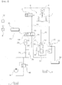
- Fig. 2 is a hydraulic circuit diagram showing the brake release control operation of the brake control valve to rotate the swing motor in accordance with a preferred embodiment of the present invention
- Fig. 3 is a hydraulic circuit diagram as shown in Fig. 2 , showing the flow of a hydraulic pressure when a brake control valve is operated to be closed to brake the swing motor at a normal condition.
- Fig. 2 shows a hydraulic circuit diagram for describing the braking operation of the swing motor brake in accordance with a preferred embodiment of the present invention.
- a reference numeral denotes a swing motor brake
- a reference numeral 9 denotes a pilot pump
- a reference numeral 10 denotes a swing motor
- a reference numeral denotes a brake control valve
- a reference numeral 17 denotes a drain control valve
- a reference numeral 20 denotes a signal pressure control valve
- a reference numeral 33 denotes a controller
- a reference numeral 32 denotes a switch
- a reference numeral 40 denotes a relief valve.
- the hydraulic control apparatus for a construction machine 1 in accordance with the present invention is configured such that the release operation of the swing motor brake 5 is performed by a hydraulic pressure discharged from the pilot pump 9 in the construction machine 1 including an excavator, and the hydraulic pressure is drained to a hydraulic tank T by the drain control valve 17 without passing through the relief valve 40 when the brake control valve 11 is shifted to allow the swing motor brake 5 to be released.
- a hydraulic control apparatus for a construction machine in accordance with the present invention includes a pilot pump 9 that is configured to provide a pilot hydraulic pressure, and a swing motor 10 that is configured to swingably rotate an upper swing structure.
- the swing motor 10 is driven by a hydraulic pressure, and can be supplied with the hydraulic pressure from a swing pump (not shown) installed at a known excavator.
- a swing control valve (not shown) that changes a direction of the hydraulic pressure discharged from the swing pump can convert the rotation direction of the swing motor 10.
- the rotation or swing of the upper swing structure 2 is performed in the traveling or construction work.
- the hydraulic control apparatus for a construction machine in accordance with the present invention includes a swing motor brake 5 that is coupled to the swing motor 10 to brake the swing motor 10 at a normal condition and is released to rotate the swing motor 10 when the pilot hydraulic pressure is supplied thereto, and a brake control valve 11 that is installed between the pilot pump 9 and the swing motor brake 5 and is configured to control a direction of the pilot hydraulic pressure or hydraulic fluid discharged from the pilot pump 9 to allow for the braking and release of the swing motor brake 5.
- the brake control valve 11 may include a supply port 12, a return port 13, and a solenoid 14 that is driven in response to an electrical control signal or a command signal.
- the swing motor brake 5 includes a brake cylinder 6 and a multi-disk brake 7.
- a piston of the brake cylinder 6 is elastically supported so that the multi-disk brake 7 is coupled to the swing motor 10 by a frictional force to restrict the rotation of the swing motor 10 in the normal state.
- normal condition is intended to understand a work condition of the construction machine in which the upper swing structure 2 are not required to be rotated.
- the term "normal state” should be construed as including a state in which a swing pump or a swash plate control device for the swing pump is controlled to a neutral position and a state in which there are no a pilot signal pressure or an electrical control signal according to the manipulation of a manipulation lever or a joystick, and a command signal corresponding to the manipulation.
- the hydraulic control apparatus for a construction machine includes: a controller 33 that is configured to receive a command signal for driving the swing motor 10 and apply the received command signal to the brake control valve 11; a relief valve 40 that is installed between the brake control valve 11 and the pilot pump 9 and, if a hydraulic pressure that exceeds a predetermined relief pressure is generated between the brake control valve 11 and the pilot pump 9, is configured to allow the hydraulic pressure to be returned to a hydraulic tank T; and a drain control valve 17 that is installed in parallel with the brake control valve 11 and configured to be opened or closed so that the pilot hydraulic pressure is selectively returned to the hydraulic tank T depending on a state of the brake control valve 11.
- the drain control valve 17 may include an inlet port 18 to which the hydraulic fluid from the pilot pump 9 is introduced, and a solenoid 19 that is driven in response to an electrical control signal or a command signal.
- the drain control valve 17 is closed.
- the brake control valve 11 is shifted to restrict the rotation of the swing motor 10 or allow for the braking of the swing motor brake 5
- the drain control valve 17 is opened so that the hydraulic pressure is drained to the hydraulic tank T without passing through the relief valve 40.
- the hydraulic control apparatus for a construction machine in accordance with the present invention further includes an accumulator 23 that is installed in a supply line 30 formed between the brake control valve 11 and the pilot pump 9 and is configured to store the hydraulic fluid that is discharged from the pilot pump 9.
- a filter 24 may be provided between the pilot pump 9 and the accumulator 23 in consideration of viscosity and performance of the hydraulic fluid on the supply line 20.
- a check valve 25 may be further provided between the pilot pump 9 and the accumulator 23 to prevent the backflow of the hydraulic fluid from the accumulator 23.
- the hydraulic control apparatus for a construction machine in accordance with the present invention further includes a switch 32 that is installed to be electrically connected to the controller 33, and a signal pressure control valve 20 that is installed on a downstream side of the drain control valve 17 and is opened or closed so as to control the pilot hydraulic pressure that passes through the drain control valve 17 depending on a manipulation of the switch 32.
- the signal pressure control valve 20 may include an inlet port 21 for a pilot signal pressure, and a solenoid 22 for a control signal that depends on the manipulation of the switch 32.
- the controller 33 may be configured as an electronic control unit (ECU) or a vehicle electronic control unit (VECU) for the construction machine.
- the controller 33 controls the brake control valve 11 to be opened or closed depending on a manipulation signal that is applied thereto from a swing joystick or a work apparatus manipulation lever 8.
- the controller 33 that processes a predetermined command signal can receive an electrical signal as a manipulation signal from the joystick 8 to swing or rotate the upper swing structure 2, and output a control signal for application to the brake control valve 11 or the drain control valve 17 to open and close the brake control valve 11 or the drain control valve 17 in response to the manipulation signal from the joystick 8.
- the control signal includes an electric solenoid control signal, and can be separately or simultaneously applied to the brake control valve 11 and the drain control valve 17.
- a traveling control valve 34 is installed at a downstream side of the signal pressure control valve 20 in such a manner as to be connected to the signal pressure control valve 20.
- the traveling control valve 34 is configured as a first or second traveling speed control valve.
- the brake control valve 11 is maintained in a closed state so that the swing motor brake 5 brakes the swing motor 10 to restrict the rotation of the swing motor 10 at a normal condition.
- the hydraulic fluid or the pilot hydraulic pressure discharged from the pilot pump 9 can be drained to the hydraulic tank T through the drain control valve 17 without passing through the relief valve 40.
- the hydraulic fluid or the pilot hydraulic pressure discharged from the pilot pump 9 can be drained to the hydraulic tank T through the drain control valve 17 without passing through the relief valve 40.
- the swing motor brake 5 When an operator performs the operation of the work apparatus 4 or the upper swing structure 2, the swing motor brake 5 is released.
- the controller 33 receives an electrical signal according to the manipulation of the joystick as a command signal corresponding to the release of the brake and applies a valve control command signal for the release of the swing motor brake 5 to the brake control valve 11.
- the controller 33 applies a command signal to the brake control valve 11 to cause the brake control valve 11 to be opened.
- the brake control valve 11 When the command signal which is an electrical control signal is applied to the solenoid 14 of the brake control valve 11, the brake control valve 11 is opened by the movement or stroke of the solenoid 14.
- the hydraulic fluid or pilot hydraulic pressure discharged from the pilot pump 9 is supplied to the brake cylinder 6 via the supply line 30, the supply port 20, and a brake hydraulic line 31.
- the drain control valve 17 is maintained in a closed state, and the hydraulic fluid or pilot hydraulic pressure discharged from the pilot pump 9 can be supplied to the brake cylinder 6 without being drained via a drain line 36.
- the rotation direction of the swing motor 10 depends on the control of the direction of the pilot hydraulic pressure by the swing control valve, and thus the swingable rotation of the upper swing structure 2 is performed.
- the swing motor brake 5 is maintained in the braking state to brake the swing motor 10 by the engagement between the swing motor 10 and the brake disk 7.
- the brake control valve 11 is maintained in a closed state in response to the command signal of the controller 33.
- the brake control valve 11 is closed in response to the command signal applied thereto from the controller 33, and the hydraulic fluid or pilot hydraulic pressure discharged from the pilot pump 9 can be filled in the accumulator 24 via the filter 24.
- a hydraulic pressure applied to the supply line 30 between the pilot pump 9 and the brake control valve 11 is introduced into the inlet port 18 of the drain control valve 17 via a parallel flow path 36 connected to the supply line 30.
- a predetermined command signal or control signal from the controller 33 is applied to the solenoid 19 of the drain control valve 17 to drain the hydraulic pressure introduced into the inlet port 18, and thus the drain control valve 17 is opened so that the hydraulic pressure applied from the pilot pump 9 to the supply line 30, is drained to the hydraulic tank T via the drain control valve 17 through the parallel flow path 36 and the inlet port 18 without passing through the relief valve 40.
- a load applied to the relief valve 40 is significantly reduced by a function of controlling the drain flow rate of the drain control valve 17, and the energy efficiency of the hydraulic system is improved.
- the signal pressure control valve 20 is maintained in a closed state.
- the hydraulic fluid or pilot hydraulic pressure discharged from the pilot pump 9 can be supplied as a predetermined pilot signal pressure.
- the drain control valve 17 is closed in response to the predetermined command signal from the controller 33, and thus the hydraulic pressure applied from the pilot pump 9 to the supply line 30 is introduced into the inlet port 21 of the signal pressure control valve 20 through the parallel flow path 36 and a signal pressure line 37.
- the signal pressure control valve 20 is switched to an opened state in response to a manipulation signal from the switch 32.
- the hydraulic pressure from the pilot pump 9, which is introduced into the inlet port 21 through signal pressure line 37, is supplied, as a pilot signal pressure, to the traveling control valve 34.
- the traveling control valve 34 is configured as a first or second traveling speed control valve
- the pilot signal pressure can be supplied as a signal pressure for the shift of a valve spool for changing the traveling speed of the lower traveling structure 3.
- the drain control valve 17 is opened in response to the command signal from the controller 33, and the hydraulic pressure applied from the pilot pump 9 to the supply line 30 is drained to the hydraulic tank T through the drain control valve 17 via the inlet port 18.
- the hydraulic fluid discharged from the pilot pump is automatically drained to the hydraulic tank by the drain control valve without passing through the relief valve in the braking state of the swing motor brake so that the hydraulic control apparatus can be useful for promotion of the reduction in a load of the relief valve and the improvement of the energy efficiency of the hydraulic system.
Landscapes
- Engineering & Computer Science (AREA)
- General Engineering & Computer Science (AREA)
- Mining & Mineral Resources (AREA)
- Civil Engineering (AREA)
- Structural Engineering (AREA)
- Mechanical Engineering (AREA)
- Transportation (AREA)
- Physics & Mathematics (AREA)
- Fluid Mechanics (AREA)
- Operation Control Of Excavators (AREA)
- Fluid-Pressure Circuits (AREA)
Applications Claiming Priority (1)
| Application Number | Priority Date | Filing Date | Title |
|---|---|---|---|
| PCT/KR2013/005743 WO2014208796A1 (ko) | 2013-06-28 | 2013-06-28 | 건설기계용 유압제어장치 |
Publications (2)
| Publication Number | Publication Date |
|---|---|
| EP3015608A1 true EP3015608A1 (de) | 2016-05-04 |
| EP3015608A4 EP3015608A4 (de) | 2017-04-12 |
Family
ID=52142113
Family Applications (1)
| Application Number | Title | Priority Date | Filing Date |
|---|---|---|---|
| EP13887856.6A Withdrawn EP3015608A4 (de) | 2013-06-28 | 2013-06-28 | Hydraulische drucksteuerungsvorrichtung für baumaschinen |
Country Status (6)
| Country | Link |
|---|---|
| US (1) | US9618019B2 (de) |
| EP (1) | EP3015608A4 (de) |
| KR (1) | KR101763283B1 (de) |
| CN (1) | CN105339563A (de) |
| CA (1) | CA2916444C (de) |
| WO (1) | WO2014208796A1 (de) |
Cited By (1)
| Publication number | Priority date | Publication date | Assignee | Title |
|---|---|---|---|---|
| CN113009937A (zh) * | 2021-04-19 | 2021-06-22 | 福州大学 | 面向阵列式开关阀的流量控制系统及控制方法 |
Families Citing this family (4)
| Publication number | Priority date | Publication date | Assignee | Title |
|---|---|---|---|---|
| KR102514523B1 (ko) * | 2015-12-04 | 2023-03-27 | 현대두산인프라코어 주식회사 | 건설기계의 유압 제어 장치 및 유압 제어 방법 |
| US10435867B2 (en) * | 2016-12-28 | 2019-10-08 | Kubota Corporation | Hydraulic system for working machine |
| JP7204330B2 (ja) | 2018-02-28 | 2023-01-16 | 株式会社小松製作所 | 積込機械の制御装置および制御方法 |
| US11415154B2 (en) * | 2019-04-12 | 2022-08-16 | Husco International, Inc. | Hydraulic systems and methods for nested pressure regulating valves |
Family Cites Families (17)
| Publication number | Priority date | Publication date | Assignee | Title |
|---|---|---|---|---|
| DE3346973A1 (de) * | 1983-12-24 | 1985-07-04 | Kabushiki Kaisha Komatsu Seisakusho, Tokio/Tokyo | Hydraulische steuervorrichtung fuer fahrzeuge mit schwenkbarem arbeitsgeraet |
| FR2646133B1 (fr) * | 1989-04-19 | 1991-08-16 | Equip Minier Sa | Dispositif de freinage pour vehicule de travaux, notamment de mines ou de carrieres |
| JPH0971977A (ja) * | 1995-09-05 | 1997-03-18 | Hitachi Constr Mach Co Ltd | 油圧モータ制御回路 |
| JP3023541B2 (ja) * | 1996-05-17 | 2000-03-21 | 住友建機株式会社 | 建設機械の旋回モータのブレーキ回路 |
| KR100286517B1 (ko) * | 1996-12-03 | 2001-04-16 | 사쿠마 하지메 | 건설 기계용 제어 장치 |
| JP3393821B2 (ja) | 1999-01-08 | 2003-04-07 | 住友建機製造株式会社 | 建設機械の旋回ロック装置 |
| JP2001165111A (ja) * | 1999-12-07 | 2001-06-19 | Kobelco Contstruction Machinery Ltd | 油圧駆動ウインチの制御装置 |
| KR100641385B1 (ko) * | 2001-12-20 | 2006-10-31 | 볼보 컨스트럭션 이키프먼트 홀딩 스웨덴 에이비 | 중장비용 선회감속 유압회로 |
| JP2005330070A (ja) * | 2004-05-21 | 2005-12-02 | Tadano Ltd | 作業機の旋回装置 |
| KR101325440B1 (ko) * | 2006-12-04 | 2013-11-04 | 두산인프라코어 주식회사 | 굴삭기 선회모터의 선회제어장치 |
| JP5083202B2 (ja) * | 2008-12-26 | 2012-11-28 | コベルコ建機株式会社 | 建設機械の旋回ブレーキ装置 |
| KR101676779B1 (ko) * | 2009-02-03 | 2016-11-17 | 볼보 컨스트럭션 이큅먼트 에이비 | 스윙 시스템 및 스윙 시스템을 포함하는 건설 기계 혹은 차량 |
| KR101640606B1 (ko) | 2009-12-24 | 2016-07-18 | 두산인프라코어 주식회사 | 건설기계의 선회 브레이크 제어장치 |
| CN102985704B (zh) * | 2010-06-30 | 2015-09-09 | 沃尔沃建造设备有限公司 | 用于施工机械液压泵的控制装置 |
| JP5185349B2 (ja) * | 2010-10-08 | 2013-04-17 | 日立建機株式会社 | ハイブリッド式建設機械 |
| CN103221695B (zh) | 2010-11-30 | 2015-11-25 | 沃尔沃建造设备有限公司 | 用于施工机械的液压泵控制系统 |
| CN102359133B (zh) * | 2011-09-27 | 2013-09-18 | 山推工程机械股份有限公司 | 一种推土机液压系统 |
-
2013
- 2013-06-28 US US14/900,531 patent/US9618019B2/en not_active Expired - Fee Related
- 2013-06-28 WO PCT/KR2013/005743 patent/WO2014208796A1/ko active Application Filing
- 2013-06-28 KR KR1020157036045A patent/KR101763283B1/ko active IP Right Grant
- 2013-06-28 CA CA2916444A patent/CA2916444C/en not_active Expired - Fee Related
- 2013-06-28 CN CN201380077878.9A patent/CN105339563A/zh active Pending
- 2013-06-28 EP EP13887856.6A patent/EP3015608A4/de not_active Withdrawn
Cited By (1)
| Publication number | Priority date | Publication date | Assignee | Title |
|---|---|---|---|---|
| CN113009937A (zh) * | 2021-04-19 | 2021-06-22 | 福州大学 | 面向阵列式开关阀的流量控制系统及控制方法 |
Also Published As
| Publication number | Publication date |
|---|---|
| EP3015608A4 (de) | 2017-04-12 |
| WO2014208796A1 (ko) | 2014-12-31 |
| US20160146230A1 (en) | 2016-05-26 |
| CA2916444A1 (en) | 2014-12-31 |
| US9618019B2 (en) | 2017-04-11 |
| CN105339563A (zh) | 2016-02-17 |
| CA2916444C (en) | 2017-09-26 |
| KR20160015262A (ko) | 2016-02-12 |
| KR101763283B1 (ko) | 2017-07-31 |
Similar Documents
| Publication | Publication Date | Title |
|---|---|---|
| US8881519B2 (en) | Slewing type working machine | |
| US11274417B2 (en) | Hydraulic drive system of construction machine | |
| EP2706151B1 (de) | Schwenkende arbeitsmaschine | |
| US9618019B2 (en) | Hydraulic pressure control device for construction machinery | |
| US20050204734A1 (en) | Hydraulic control system for hydraulic excavator | |
| EP3106677B1 (de) | Hydraulische antriebsvorrichtung für baumaschine | |
| CN104755770B (zh) | 作业机械 | |
| KR101928594B1 (ko) | 작업 기계의 유압 구동 장치 | |
| KR20130124278A (ko) | 하이브리드식 건설 기계 | |
| CN104769193B (zh) | 挖土机 | |
| CN108884842B (zh) | 液压系统以及紧急情况操作方法 | |
| EP3093398A1 (de) | Steuerschaltung und steuerungsverfahren für auslegerenergierückgewinnung | |
| CN104812966A (zh) | 挖土机 | |
| JP2015090192A (ja) | 流体圧回路および作業機械 | |
| JP6013503B2 (ja) | 建設機械 | |
| KR101747519B1 (ko) | 하이브리드식 건설 기계 | |
| JP2011017431A (ja) | 電動油圧旋回駆動装置 | |
| JP6261002B2 (ja) | 流体圧回路および作業機械 | |
| JP7152968B2 (ja) | 油圧ショベル駆動システム | |
| KR102246421B1 (ko) | 건설기계의 제어 시스템 및 건설기계의 제어 방법 | |
| JP2014206022A (ja) | 建設機械の旋回制動装置 | |
| JP7165016B2 (ja) | 油圧ショベル駆動システム | |
| JP6615868B2 (ja) | ショベルおよびショベルの駆動方法 | |
| JP2006064139A (ja) | 作業機の油圧駆動ユニット |
Legal Events
| Date | Code | Title | Description |
|---|---|---|---|
| PUAI | Public reference made under article 153(3) epc to a published international application that has entered the european phase |
Free format text: ORIGINAL CODE: 0009012 |
|
| 17P | Request for examination filed |
Effective date: 20151222 |
|
| AK | Designated contracting states |
Kind code of ref document: A1 Designated state(s): AL AT BE BG CH CY CZ DE DK EE ES FI FR GB GR HR HU IE IS IT LI LT LU LV MC MK MT NL NO PL PT RO RS SE SI SK SM TR |
|
| AX | Request for extension of the european patent |
Extension state: BA ME |
|
| DAX | Request for extension of the european patent (deleted) | ||
| A4 | Supplementary search report drawn up and despatched |
Effective date: 20170315 |
|
| RIC1 | Information provided on ipc code assigned before grant |
Ipc: B60T 13/22 20060101ALI20170309BHEP Ipc: E02F 9/22 20060101AFI20170309BHEP Ipc: E02F 9/12 20060101ALI20170309BHEP Ipc: F15B 13/02 20060101ALI20170309BHEP |
|
| STAA | Information on the status of an ep patent application or granted ep patent |
Free format text: STATUS: THE APPLICATION IS DEEMED TO BE WITHDRAWN |
|
| 18D | Application deemed to be withdrawn |
Effective date: 20190103 |