EP3015259B1 - Papier d'enveloppe - Google Patents
Papier d'enveloppe Download PDFInfo
- Publication number
- EP3015259B1 EP3015259B1 EP15194168.9A EP15194168A EP3015259B1 EP 3015259 B1 EP3015259 B1 EP 3015259B1 EP 15194168 A EP15194168 A EP 15194168A EP 3015259 B1 EP3015259 B1 EP 3015259B1
- Authority
- EP
- European Patent Office
- Prior art keywords
- envelope
- paper
- sheet
- pressure
- envelope sheet
- Prior art date
- Legal status (The legal status is an assumption and is not a legal conclusion. Google has not performed a legal analysis and makes no representation as to the accuracy of the status listed.)
- Not-in-force
Links
Images


Classifications
-
- B—PERFORMING OPERATIONS; TRANSPORTING
- B31—MAKING ARTICLES OF PAPER, CARDBOARD OR MATERIAL WORKED IN A MANNER ANALOGOUS TO PAPER; WORKING PAPER, CARDBOARD OR MATERIAL WORKED IN A MANNER ANALOGOUS TO PAPER
- B31B—MAKING CONTAINERS OF PAPER, CARDBOARD OR MATERIAL WORKED IN A MANNER ANALOGOUS TO PAPER
- B31B70/00—Making flexible containers, e.g. envelopes or bags
- B31B70/60—Uniting opposed surfaces or edges; Taping
-
- B—PERFORMING OPERATIONS; TRANSPORTING
- B43—WRITING OR DRAWING IMPLEMENTS; BUREAU ACCESSORIES
- B43M—BUREAU ACCESSORIES NOT OTHERWISE PROVIDED FOR
- B43M3/00—Devices for inserting documents into envelopes
- B43M3/04—Devices for inserting documents into envelopes automatic
-
- B—PERFORMING OPERATIONS; TRANSPORTING
- B43—WRITING OR DRAWING IMPLEMENTS; BUREAU ACCESSORIES
- B43M—BUREAU ACCESSORIES NOT OTHERWISE PROVIDED FOR
- B43M5/00—Devices for closing envelopes
- B43M5/04—Devices for closing envelopes automatic
-
- B—PERFORMING OPERATIONS; TRANSPORTING
- B43—WRITING OR DRAWING IMPLEMENTS; BUREAU ACCESSORIES
- B43M—BUREAU ACCESSORIES NOT OTHERWISE PROVIDED FOR
- B43M5/00—Devices for closing envelopes
- B43M5/04—Devices for closing envelopes automatic
- B43M5/047—Devices for closing envelopes automatic using pressure-sensitive adhesive
-
- B—PERFORMING OPERATIONS; TRANSPORTING
- B65—CONVEYING; PACKING; STORING; HANDLING THIN OR FILAMENTARY MATERIAL
- B65D—CONTAINERS FOR STORAGE OR TRANSPORT OF ARTICLES OR MATERIALS, e.g. BAGS, BARRELS, BOTTLES, BOXES, CANS, CARTONS, CRATES, DRUMS, JARS, TANKS, HOPPERS, FORWARDING CONTAINERS; ACCESSORIES, CLOSURES, OR FITTINGS THEREFOR; PACKAGING ELEMENTS; PACKAGES
- B65D27/00—Envelopes or like essentially-rectangular flexible containers for postal or other purposes having no structural provision for thickness of contents
- B65D27/12—Closures
- B65D27/14—Closures using adhesive applied to integral parts, e.g. flaps
-
- B—PERFORMING OPERATIONS; TRANSPORTING
- B65—CONVEYING; PACKING; STORING; HANDLING THIN OR FILAMENTARY MATERIAL
- B65D—CONTAINERS FOR STORAGE OR TRANSPORT OF ARTICLES OR MATERIALS, e.g. BAGS, BARRELS, BOTTLES, BOXES, CANS, CARTONS, CRATES, DRUMS, JARS, TANKS, HOPPERS, FORWARDING CONTAINERS; ACCESSORIES, CLOSURES, OR FITTINGS THEREFOR; PACKAGING ELEMENTS; PACKAGES
- B65D27/00—Envelopes or like essentially-rectangular flexible containers for postal or other purposes having no structural provision for thickness of contents
- B65D27/32—Opening devices incorporated during envelope manufacture
- B65D27/34—Lines of weakness
-
- B—PERFORMING OPERATIONS; TRANSPORTING
- B65—CONVEYING; PACKING; STORING; HANDLING THIN OR FILAMENTARY MATERIAL
- B65D—CONTAINERS FOR STORAGE OR TRANSPORT OF ARTICLES OR MATERIALS, e.g. BAGS, BARRELS, BOTTLES, BOXES, CANS, CARTONS, CRATES, DRUMS, JARS, TANKS, HOPPERS, FORWARDING CONTAINERS; ACCESSORIES, CLOSURES, OR FITTINGS THEREFOR; PACKAGING ELEMENTS; PACKAGES
- B65D27/00—Envelopes or like essentially-rectangular flexible containers for postal or other purposes having no structural provision for thickness of contents
- B65D27/32—Opening devices incorporated during envelope manufacture
- B65D27/36—Finger openings, slots, or gripping tabs
-
- G—PHYSICS
- G03—PHOTOGRAPHY; CINEMATOGRAPHY; ANALOGOUS TECHNIQUES USING WAVES OTHER THAN OPTICAL WAVES; ELECTROGRAPHY; HOLOGRAPHY
- G03G—ELECTROGRAPHY; ELECTROPHOTOGRAPHY; MAGNETOGRAPHY
- G03G15/00—Apparatus for electrographic processes using a charge pattern
- G03G15/65—Apparatus which relate to the handling of copy material
- G03G15/6588—Apparatus which relate to the handling of copy material characterised by the copy material, e.g. postcards, large copies, multi-layered materials, coloured sheet material
- G03G15/6594—Apparatus which relate to the handling of copy material characterised by the copy material, e.g. postcards, large copies, multi-layered materials, coloured sheet material characterised by the format or the thickness, e.g. endless forms
-
- G—PHYSICS
- G03—PHOTOGRAPHY; CINEMATOGRAPHY; ANALOGOUS TECHNIQUES USING WAVES OTHER THAN OPTICAL WAVES; ELECTROGRAPHY; HOLOGRAPHY
- G03G—ELECTROGRAPHY; ELECTROPHOTOGRAPHY; MAGNETOGRAPHY
- G03G2215/00—Apparatus for electrophotographic processes
- G03G2215/00362—Apparatus for electrophotographic processes relating to the copy medium handling
- G03G2215/00367—The feeding path segment where particular handling of the copy medium occurs, segments being adjacent and non-overlapping. Each segment is identified by the most downstream point in the segment, so that for instance the segment labelled "Fixing device" is referring to the path between the "Transfer device" and the "Fixing device"
- G03G2215/00417—Post-fixing device
- G03G2215/00426—Post-treatment device adding qualities to the copy medium product
-
- G—PHYSICS
- G03—PHOTOGRAPHY; CINEMATOGRAPHY; ANALOGOUS TECHNIQUES USING WAVES OTHER THAN OPTICAL WAVES; ELECTROGRAPHY; HOLOGRAPHY
- G03G—ELECTROGRAPHY; ELECTROPHOTOGRAPHY; MAGNETOGRAPHY
- G03G2215/00—Apparatus for electrophotographic processes
- G03G2215/00362—Apparatus for electrophotographic processes relating to the copy medium handling
- G03G2215/00443—Copy medium
- G03G2215/00514—Envelopes
Definitions
- the present invention relates to a sealed letter producing device which is capable of printing on a paper sheet which serves as an envelope a paper sheet of a content, and performing the operation of enclosing and sealing a content in the envelope by folding the paper sheet which becomes the envelope with a simple configuration, and such a device suitable for an envelope sheet (a paper sheet which forms an envelope when folded).
- Patent document 1 described below discloses an invention relating to a method for producing a sealed letter by folding in three.
- An envelope sheet which is substantially similar to a sealed letter form used in this invention is shown in Figs. 31 and 32 .
- this envelope sheet 300 includes three paper pieces: an upper paper piece 301, a middle paper piece 302, and a lower paper piece 303, connected by perforations. Name and address are written on the front side of the upper paper piece 301, contents are written on the front sides the middle paper piece 302 and lower paper piece 303.
- a pressure-sensitive adhesive 305 is formed in an approximate square U-shape and in a band-shaped pattern along the external forms of two paper piece other than perforations. No pressure-sensitive adhesive is present on the front side of the upper paper piece 301 which will finally be the other surface. Moreover, nothing is written on the back sides of the upper paper piece 301, the middle paper piece 302 and lower paper piece 303, or a printing pattern is formed to prevent the content from being seen through.
- the pressure-sensitive adhesive 305 is formed in a band-shaped pattern along the outer edge other than perforations and part of the sides. No pressure-sensitive adhesive is present on the back side of the lower paper piece 301 which will be the outer back side finally.
- the envelope sheet 300 After name, address, contents and other information are printed, in the case where the envelope sheet 300 is formed into the shape of the envelope, the front side of the middle paper piece 302 and the front side of the lower paper side 303 are placed together as shown in Fig. 19 and the pressure-sensitive adhesives 305 on both paper pieces are brought into contact with each other. Furthermore, as shown in Fig. 19 , the back side of the upper paper side 301 and the back side of the middle paper side 302 are placed together to bring the pressure-sensitive adhesives 305 on both paper pieces into contact with each other.
- the envelope sheet 300 is in the form of a folded-in-three envelope in this state, but the pressure-sensitive adhesives 305 are not adhered yet.
- the envelope is nipped by a pair of rollers whose size in the axial direction is greater than their length in the width direction of the envelope, and is transferred while applying a high pressure on the entire surface of the envelope.
- a pressure is applied to the entire surface of the envelope by two pairs of rollers which are longer than the width of the envelope. Accordingly, the pressure-sensitive adhesives which are in contact with each other between the paper pieces facing each other develops tackiness, and a sealed envelope, that is, a sealed letter is produced.
- Patent document 1 Japanese Patent Publication No. 2521498 .
- US 6019280 discloses a mailer having an included postcard which is used as a reply piece.
- the postcard is defined by lines of weakness in the first and second faces of the mailer.
- US 5829670 discloses a mailer having particular patterns of pressure activated adhesive in separable margins which prevent flexing or distortion of the vertical edges.
- US 2010/0089990 discloses an envelope having an integrated return mailing article fabricated from a single sheet of material.
- the adhered portion only needs to be pressurized, and therefore maintenance is unnecessary. Since the sealed letter producing device is simpler than a device using adhesives such as hot melts, it can be a relatively small device.
- the pressure applied on the adhered portion of the envelope is as high as about 1 ton/square centimeter, and the adhered portion in the example described above is present on three to four sides of the rectangular envelope, and therefore rollers longer than the width of the envelope have been necessary so that a pressure can be applied the entire surface of the envelope having a predetermined area (refer to Fig. 4 of patent document 1 mentioned above). If such pressure rollers are to be provided, the mechanical structure of the entire device must be robust. Such a device is a costly device consequently, and it has not been spread as an office installation device accordingly.
- the present invention has been made in view of the objects as described above, and its object is to provide a sealed letter producing device for performing printing on the envelope sheet and content, and enclosing and sealing of the folded envelope sheet, in which sealing using a pressure-sensitive adhesive can be performed with a simple configuration using pressure rollers smaller than conventional ones.
- the inventors of the present invention obtained the above objects and examined various solutions to the objects, and considered using other adhesives than pressure-sensitive adhesives during the examination.
- some of few possible examples of adhesives cheaper than pressure-sensitive adhesives are remoistening pastes such as mucilage.
- remoistening pastes application of water is necessary to develop adhesive strength.
- the material forming an envelope is paper, when the paper contains water, a considerable reduction in rigidity and deformation of the paper occur due to swelling.
- adhesion using a remoistening paste such as mucilage can be used for simple adhesion between two sheets, but in the adhesion of three or four sheets such as production of a sealed letter performed by folding the envelope sheet to which the present invention is directed, swelling is markedly increased, which likely leads to the occurrence of the problems such as a significant reduction in rigidity and breakage. Moreover, since deformation of the paper sheet remains after drying, using a remoistening paste such as mucilage in an adhered portion of parts of the folded envelope sheet stacked in a plurality of layers is considered impossible as it is.
- a sealed letter producing device is an envelope sheet applied to a sealed letter producing device including an enclosing and sealing unit which produces a sealed letter by enclosing and sealing a content by folding an envelope sheet in a manner of containing the content, said envelope sheet including two folds which are parallel to a width direction of the envelope sheet dividing the sheet into first, second and third paper pieces, the first, the second and the third paper pieces having a common length in the width direction, the content being placed between the second and the third paper pieces, said envelope sheet further including a surface and a back side, wherein the envelope sheet has pressure sensitive adhesives provided in both edge portions of the first, the second and the third paper pieces in the width direction, said pressure sensitive adhesives being provided only on one side of the surface or the back side in the both edge portions in its width direct, notches provided in both edge portions of the third paper piece of the sheet which becomes an inner paper piece when bent, the third paper piece holding the content while being sandwiched between the first and the second paper pieces, characterized in that
- the pressure sensitive adhesives are provided only on one side of both edge portions in its width direction. Accordingly, the pressure sensitive adhesives do not face each other and are not adhered when stacked in the same orientation. Moreover, when formed on the envelope by folding, the pressure sensitive adhesives face each other directly in both edge portions of the envelope, or the pressure sensitive adhesives provided in both edge portions of one of the outer sides face the pressure sensitive adhesives provided in both edge portions of the other outer side via the notches provided in both edge portions bent to be an inside face.
- the envelope sheet further comprises a remoistening paste provided on the third paper piece.
- Fig. 1 is a drawing which shows the surface (the side on which the name and address are printed) of an envelope sheet 100 used in this arrangement
- Fig. 2 is a drawing which shows the back side of the same.
- This envelope sheet 100 is a rectangular paper sheet including three paper pieces: a first paper piece 101, a second paper piece 102, and a third paper piece 103, which are connected by folds.
- the surface of the first paper piece 101 corresponds to the front side of the envelope, on which name and address are printed.
- the first paper piece 101 has a band-shaped opening tape 104 along its width direction formed thereon by perforation, and two openings 105 are provided at an end thereof.
- the opening tape 104 is torn off along the perforation by placing a finger on the opening tape 104 from this opening 105.
- the surface of the second paper piece 102 corresponds to the back side of the envelope, on which the name, address, etc. of the sender are printed.
- Pressure-sensitive adhesives 106 are provided in two portions along at a predetermined interval at both edge portions in the width direction on the surface of the third paper piece 103 in the form of bands.
- two portions of remoistening pastes 107 are provided on the inner side of both edge portions close to the fold bordering the second paper piece 102 in a band-shaped pattern along the width direction.
- a pressure-sensitive adhesive exhibits adhesive strength by adhering pressure-sensitive adhesives provided on two sheets of paper together and applying a predetermined pressure.
- Its known examples include two-pack type adhesive using microcapsules and natural rubber-based adhesion materials, among others.
- the remoistening paste is, for example, mucilage or the like.
- the remoistening paste has no adhesive strength when it is applied on paper and dry, but develops adhesive strength when wetted with water, and when the paper sheet is placed together with another paper sheet in this state and a required pressure is applied thereto, the two paper sheets are adhered.
- the pressure required for adhesion with a remoistening paste is effective even when it is significantly lower than the pressure required for a pressure-sensitive adhesive.
- an adhesive which does not normally have adhesive strength but develops adhesive strength by any operation other than the pressure as for the pressure-sensitive adhesive may be used.
- adhesives which develop adhesive strength by heat, light including ultraviolet radiation, and other physical sections, other pressure-sensitive adhesives which develop adhesive strength with a pressure lower than that applied on the pressure-sensitive adhesive may be used.
- the remoistening paste requires application of water to develop adhesive strength. Since the material forming an envelope is paper, when the paper contains water, a considerable reduction in rigidity and deformation of the paper occur due to swelling. Moreover, since deformation of the paper sheet remains after drying, the appearance of the finished envelope is deteriorated. Therefore, deformation is minimized by divisionally placing a plurality of small sized portions of the remoistening paste within an adhesion area where the paste is required.
- each of the first to third paper pieces 101 to 103 on the surface of each of the first to third paper pieces 101 to 103, if necessary, the contents of the sealed letter, including the information such as text, graphics and photographs, can be printed.
- the pressure-sensitive adhesives 106 are provided in two portions along both edge portions in the width direction at a predetermined interval.
- a content 40 is mounted on the back side of the second paper piece 102.
- a width W of the content 40 is smaller than the interval between the pressure-sensitive adhesives 106 printed in both edge portions of the paper piece of the envelope sheet 100.
- the arrangement pattern of these pressure-sensitive adhesives 106 is so considered that the pressure-sensitive adhesives 106 of corresponding paper pieces meet and come into contact with each other when the paper pieces are folded to be assembled in the form of an envelope.
- the pressure-sensitive adhesives 106 on the front sides and the pressure-sensitive adhesives 106 on the back sides do not face each other to avoid contact therebetween.
- the problem of natural adhesion of the adhesives may be caused by a high temperature, high humidity and other circumstances conditions even without any pressure, but such a problem can be prevented from occurring in advance according to the envelope sheet 100 of the arrangement.
- the back side of the third paper piece 103 is placed together with the second paper piece 102 and the content 40 to bring the pressure-sensitive adhesives 106 of both paper pieces 102, 103 into contact with each other.
- Fig. 4 after water is applied onto the remoistening paste 107 by a section not shown, the back side of the first paper piece 101 and the front side of the third paper piece 103 of are put together to bring the remoistening paste 107 and the back side of the first paper piece 101 into contact, and the pressure-sensitive adhesives 106 of both paper pieces 101, 103 are brought into contact with each other.
- the envelope sheet 100 is in the form of an envelope folded in three in this state, but the pressure-sensitive adhesives 106 are yet adhered.
- the entire surface of the envelope 50 is nipped by rollers (not shown) having a length equal to or greater than the width of the envelope to transfer the envelope 50, and the remoistening paste 107 of the third paper piece 103 and the first paper piece 101 are adhered.
- the pressure-sensitive adhesives 106 placed in both edge portions in the width direction of the envelope 50 are adhered by pressure rollers 80.
- a pair of these pressure rollers 80 includes upper and lower sets, and two left and right pairs of these rollers are provided.
- both edge portions in the width direction of the envelope 50 enclosing the content 40 that is, the direction intersecting the transfer direction are nipped from above and below and pressurized to develop the adhesive strength the pressure-sensitive adhesive 106 and achieve sealing.
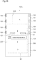
- the sealed letter producing device 1 of the first arrangement performs a process for each sealed letter to be produced. That is, required printing is performed in an appropriate order using a common printing unit 2 on the envelope sheet 100 and sheet-like paper sheet the content 40. Then, the envelope sheet 100 and the content 40 after printing are transferred into an enclosing and sealing unit 3, the envelope sheet 100 is folded so as to being the form of the envelope 50 while being transferred through the paper paths of different systems, and if necessary, the content 40 is also folded. Finally, both the envelope sheet 100 and the content 40 are merged at an enclosing and sealing section, and the content 40 is enclosed and sealed in the envelope 50 to be discharged in alignment as a finished sealed letter in an upper part of the device.
- the sealed letter producing device 1 includes a printing unit 2 which prints and discharges the paper sheets which will be the envelope 50 and the content 40.
- This printing unit 2 is provided with a plurality of paper feed racks P (PI to P4) which can accommodate more than one types of printed bodies (sheet-like paper sheet 30 which will be the content 40 and the envelope sheet 100) inside, on a side or other places of a cabinet 4 accommodates components of the device.
- the envelope sheet 100 is accommodated in a paper feed rack P1 attached to the side the cabinet 4, the sheet-like paper sheets 30 which will be the contents 40 are accommodated in paper feed racks P2 to P4 provided inside the cabinet 4.
- Paper sheets and the like discharged from these paper feed racks P are transferred into a looped transfer path 5 from an introduction path to be transported, and an image is formed by printing section disposed at predetermined intervals downwardly along the lower half of the transfer path.
- four ink jet devices C, K, M and Y which discharge cyan, black, magenta and yellow inks, respectively, are disposed as printing section.
- This looped transfer path 5 has a first discharge path 6 which discharges paper sheets to the outside of the loop in an approximately horizontal direction in a downstream adjacent portion of the printing section provided in a branching manner. Moreover, the upper half of the looped transfer path 5 has a second discharge path 7 which discharges paper sheets to the outside of the loop provided in a branching manner. In addition, a switchback path 8 is provided between the second discharge path 7 and the introduction path from the paper feed rack P in a branching manner. This switchback path 8 is a section which turns paper sheets upside down in the transfer path 5 by receiving the paper sheets transferred the transfer path 5 and then reverses the same to return to the transfer path 5.
- the enclosing and sealing unit 3 for receiving and processing the paper sheets 30 which will be the envelope sheets 100 and the contents 40 transferred from the first discharge path 6 of the printing unit 2, and enclosing and sealing the contents 40 in the envelope sheets 100 is provided.
- the first discharge path 6 of the printing unit 2 extends horizontally to protrude outwardly, and is introduced into a cabinet 9 of the enclosing and sealing unit 3 adjacent thereto.
- a second paper path 20 branches obliquely downward from this discharge path 6, and extends obliquely downwardly to be one of a first paper path 10, a path 11, further downstream thereof.
- the path 11, which is one of the first paper path 10 is disposed approximately in parallel to a path 21, which is one of the second paper path 20.
- the path 11, which is one of the first paper paths 10 is a guide path which transfers the envelope sheet 100 to a folding section, and as previously mentioned, and the path 21, which is one of the second paper paths 20, is a guide path which transfers the paper sheet of the content 40 to the folding section.
- the switching between the first and second paper paths 10 and 20 is performed by a switching flap not shown provided at the junction of the second paper path 20.
- a first folding section which folds the envelope sheet 100 to produce the form of the envelope 50 is provided.
- This first folding section is provided with a freely rotatable main folding roller A', a paper transport roller D' and a first folding roller B' which are in contact with the same and are rotated are provided.
- These rollers are made of rubber, and their pressurizing abilities are low since they are for folding paper sheets. Their lengths in the axial direction are greater than the width of the envelope sheet 100.
- a path 13 which is the other path of the first paper path 10 curves in a convex shape upwardly and extends in the horizontal direction.
- the second paper path 20 which transfers the paper sheet printed by the printing unit 2 is provided inside the cabinet 9 of the enclosing and sealing unit 3.
- This second paper path 20 is positioned below the first paper path 10, and has the path 21, which is one of the paths for obliquely downwardly transferring the paper sheet transferred in the horizontal direction from the first discharge path 6 of the printing unit 2.
- a paper transport roller 22 and an alignment portion 23 which is a freely openable and closable gate are provided, so that the paper sheets can be stacked and retained in the path 21 by fixing the transferred paper sheets on the alignment portion 23 closing the path 21.
- a folding section which folds the paper sheets is provided at an end of this path 21.
- This folding section is provided with a freely rotatable central main folding roller A, and furthermore, a first folding roller B, a second folding roller C and a single paper transport roller D are in contact with a main folding roller A, each of the rollers being freely rotatable.
- rollers are made of rubber, their pressurizing abilities are low since they are for folding paper sheets, and their lengths in the axial direction are greater than the width of the envelope sheet 100.
- an impinging member on which the front end of the transferred paper sheet impinges is provided, so that the impinging paper sheet is warped and the warped portion of the paper sheet is led in between the main folding roller A and folding roller B to fold the paper sheet.
- an impinging member is also provided in a front position in the transfer direction by the main folding roller A and folding roller B, so that the impinging paper sheet is warped the warped portion of the paper sheet is led in between the main folding roller A and folding roller C to fold the paper sheet. Therefore, according to these folding section, the paper sheet can be folded twice or more.
- the second paper path 20 has the other path 26 which continuously transfers the paper sheet 30 folded by the folding section obliquely upwardly, i.e., approximately perpendicularly to the path 21.
- This other path 26 is positioned below the above-mentioned path 13, i.e., the other path of the first paper path 10, which transfers the envelope sheet 100 obliquely downward, and joins the path 13 of the first paper path 10 at the enclosing and sealing section.
- This enclosing and sealing section is a second folding section which provides further folding with the envelope sheet 100, if necessary, while, at the same time, it is an enclosing section which encloses the content 40 in the envelope by providing the envelope sheet 100 with further folding after the content 40 is aligned with the folded envelope sheet 100, and is further provided with a sealing section which seals this envelope.
- the enclosing and sealing section is provided with the second folding section, i.e., a freely rotatable main folding roller A", a paper transport roller D" which is in contact with and rotated by the same, and first and second folding rollers B", C".
- These rollers are made of rubber. Their pressurizing abilities are low since they are for folding paper sheets, and their lengths in the axial direction are greater than the width of the envelope sheet 100.
- the envelope sheet 100 is folded, if necessary, by the main folding roller A', first folding roller B' and other components which are the above-mentioned first folding section, and then transferred further to the main folding roller A" and other components, which the second folding section, where pre-enclosure folding, if necessary, is further performed.
- the envelope sheet 100 is folded in three to enclose the content 40 therein enclose in this arrangement. Therefore after the envelope sheet 100 is folded once by the main folding roller A', first folding roller B' and other component which are the first folding section, passes between the main folding roller A" and paper transport roller D", which are the second folding section, and then stands by for the alignment with the content 40 around where it has passed between the main folding roller A" and second folding roller B". After the envelope 50 is then aligned with the content 40 transferred through the second paper path 20, it is provided with the second folding further between the main folding roller A" and second folding roller C", and enclosing of the content 40 into the envelope 50 is performed.
- a standby path 46 extends downwardly from between the main folding roller A" and paper transport roller D". Accordingly, production of sealed letters can be also performed for envelope sheets different from that in this arrangement or steps different from that in this arrangement. For example, after an envelope sheet is folded once by the main folding roller A', the first folding roller B' and other components which are the first folding section, the envelope sheet is passed between the main folding roller A" and paper transport roller D" which are the second folding section, and is caused to enter the standby path 46 in that state and put on standby. Thereafter, after a content transferred through the second paper path 20 is aligned with this envelope sheet during standby, both can be nipped between the main folding roller A" and second folding roller B", and transferred while being folded to enclose the content in the envelope.
- a path 31 slightly inclined to the back is disposed between the main folding roller A" and second folding roller C" of the enclosing and sealing section.
- a moistening section 60 as an adhesion section which applies water to the remoistening paste 107 of the envelope sheet 100 to develop adhesive strength, and adheres the envelope sheet 100 to form the envelope 50 is provided.
- the moistening section 60 is a device for moistening the remoistening paste 107 provided inwardly of both edge portions of the width direction of the envelope sheet 100.
- the moistening section 60 is provided with a water tank 61 which is disposed below the path 31, a water-absorbing portion 62 which is immersed into water in the water tank 61 and is made from a felt material or the like, a swing arm 63 disposed above the path 31, and a rotation cam 64 which drives this swing arm 63.
- the envelope sheet 100 which is folded once by the main folding roller A', the first folding roller B' and other components which are the first folding section passes between the main folding roller A" and paper transport roller D", which are the second folding section, and then stands by around where it has passed between the main folding roller A" and second folding roller B". Thereafter, the content 40 transferred along the path 26, which is another second paper path 20 is aligned with the envelope sheet 100 during standby.
- the aligned envelope sheet 100 and content 40 are further forwarded by the main folding roller A" and second folding roller B".
- the front side of the third paper piece 103 faces down, and the remoistening paste 107 on the front side of the third paper piece 103 faces the water-absorbing portion 62 of the moistening section 60.
- the rotation cam 64 is activated herein to swing the swing arm 63, and the remoistening paste 107 is pressed against the water-absorbing portion 62 to be moistened.
- the envelope sheet 100 is forwarded by the main folding roller A" and second folding roller C". This causes the first paper piece 101 to be folded, overlapped with the front side of the third paper piece 103, and adhered to the remoistening paste 107.
- a path 47 inclined obliquely forwardly is disposed between the main folding roller A" and second folding roller C" of the enclosing and sealing section.
- This path 47 is approximately parallel to the path 11 which is one of the first paper paths 10, and the path 21, which is one of the second paper paths 20.
- pressure rollers 80 as a pressure bonding section constituting a portion of the enclosing and sealing section is provided. Since the pressure rollers 80 is a section which applies a certain level of pressure the pressure-sensitive adhesive 106 of the envelope sheet 100, it is constituted by a highly rigid metal. A set of these pressure rollers 80 includes upper and lower sets of rollers, and two left and right pairs are provided. The pressure rollers 80 nip each of the edge portions of the envelope 50 in the width direction thereof in which the content 40 is enclosed from above and below to apply pressure thereon, whereby sealing by the pressure-sensitive adhesive 106 can be performed.
- each of the pressure rollers 80 is attached to at the front end of a support arm 82 caused to be swingable about a fulcrum 81.
- a biasing section 83 is attached to the rear end of this support arm 82, a set of the pressure rollers 80 are configured to come into contact with each other at a predetermined pressure. Therefore, by guiding the envelope 50 to go between a set of the pressure rollers 80, 80, and driving in the direction of transfer the pressure rollers 80, the envelope 50 is forwarded under the predetermined pressure of both edge portions.
- the pressure applied to the envelope sheet 100 by the pressure rollers 80 due to the biasing section 83 depends on the type of the pressure-sensitive adhesive 106, but may be, for example, about 700 N/cm.
- the width of the pressure rollers 80 is less than the width of application of a pressure sensitive adhesive provided in both edge portions of the width direction of the envelope sheet 100. Moreover, the interval between the left and right pairs of the pressure rollers 80, 80 is greater than the width of the content 40 enclosed in the envelope 50, and is less than the width of the envelope 50. Therefore, in a sealing step by the pressure rollers 80 only the pressure-sensitive adhesive 106 in both edge portions of the envelope 50 in the width direction can be adhered by planned pressurizing surely with an area equivalent to the width of the pressure rollers 80, and at that time, the content 40 is not pressurized by the pressure rollers 80, and therefore the content 40 is not adhered to the envelope.
- the width of the pressure-sensitive adhesives 106 provided in both edge portions of the envelope sheet 100 may be about 5 mm in consideration of a positional shift of the pressure rollers 80, while the width of the pressure rollers 80 may be about 3 mm in consideration of secured adhesion of the envelope sheet 100.
- the widths of the pressure rollers 80 are small, and only the portions of the pressure-sensitive adhesive 106 in both edge portions of an assembled envelope need to be nipped and pressurized by the pressure rollers 80, and therefore positioning in the width direction of the envelope with respect to the pressure rollers 80 needs to be correctly performed.
- a positioning roller 65 is provided between the main folding roller A" and second folding roller C" and the pressure rollers 80 in the enclosing and sealing unit of this arrangement.
- the length of the positioning roller 65 in the axial direction of is greater than the width of the envelope sheet 100, and therefore can move in the axial direction with the envelope sheet 100 left nipped therebetween to adjust the position.
- an edge sensor 66 is provided above a portion slightly downstream of the positioning roller 65, enabling capturing the edge portions of the envelope sheet 100 nipped by the positioning roller 65, and obtaining the positional information of the envelope sheet 100 to correct the position of the positioning roller 65.
- the edge sensor 66 by causing the edge sensor 66 to capture the edge portion of the envelope 50 which is being transferred by the positioning roller 65, and moving the positioning roller 65 based on the position information, the position of the envelope 50 in the width direction relative to the pressure rollers 80 can be optimally adjusted. Accordingly, only the portions of the pressure-sensitive adhesives 106 in both edge portions of the assembled envelope 50 can be surely pressurized by the pressure rollers 80.
- the sealed letter producing device 1 of this arrangement is provided with a control section 90 which controls each mechanism of the printing unit 2 and enclosing and sealing unit 3 described above.
- the control section 90 is disposed in the printing unit 2, but it may be disposed in the enclosing and sealing unit 3, or may be separately disposed outside the printing unit 2 and the enclosing and sealing unit 3.
- the sealed letter producing device 1 of this arrangement described above the overall procedure including printing of name and address and other information on the envelope sheet 100, performing required printing on a plurality of sheets of the content 40 and folding the same, enclosing the content 40 in the envelope 50 which is the folded and formed envelope sheet 100 and sealing the envelope 50 will be described.
- the envelope sheet 100 is transferred from the paper feed rack P1.
- the envelope sheet 100 may be on any of the paper feed racks P1 to P4 of the printing unit 2.
- This envelope sheet 100 is printed on it both sides by the ink jet devices C, K, M, Y during a single pass around the looped transfer path 5.
- duplex printing but also simplex printing can be selected.
- name, address and other information are printed on the face which serves as the outer face of the envelope 50, while any information to be sent to the address, if necessary, is printed on the face which serves as the inner face of the envelope 50, along with particulars of the enclosed content 40.
- the information printed on the inner face of the envelope 50 can be read by a receiver by cutting and opening the envelope 50.
- the envelope sheet 100 is transferred from the path 11, which is one of the first paper paths 10, by switching of a switching flap not shown to the folding section.
- the envelope sheet 100 is forwarded by the main folding roller A' and the paper transport roller D', impinges on an impinging member not shown to be warped, enters in between the main folding roller A' and the first folding roller B' from the warped portion, and further nipped and transferred to be provided with a fold in a portion of the front end portion thereof in the paper feed direction.
- the unfinished envelope which is partially folded passes between the main folding roller A" and paper transport roller D" of the enclosing and sealing section, further simply passes between the main folding roller A" and second folding roller B" along the path, and then stands by for the alignment with the content 40.
- the required paper sheet 30 is transferred as the content 40 from any of the paper feed racks P2 to P4 into the looped transfer path 5 at a certain determined interval, both sides of the paper sheet 30 are printed by the ink jet devices C, K, M and Y during a single pass through this transfer path. Not only duplex printing but also simplex printing can be selected.
- the paper sheet 30 of the content 40 is transferred to the path 21, which is one of the second paper paths 20, by switching of a switching flap not shown.
- the paper sheet 30 is retained at an alignment portion 23 on the path 21, which is one of the second paper paths 20 until a required number of sheets are accumulated, the alignment portion 23 opens when the required number is accumulated and the sheets are transferred into the folding section (main folding roller A, etc.).
- a plurality of folding performed by the folding section the paper sheet 30 folded in a desired state is transferred into the enclosing and sealing unit (main folding roller A", etc.) via the path 26, which is the other path of the second paper paths 20.
- the content 40 is folded inwardly in three. This content 40 is forwarded by the main folding roller A" and second folding roller B", and is aligned with the envelope sheet 100 which is on standby near these rollers.
- an operation to bend the envelope sheet 100 is performed in a manner of wrapping up the content 40 with the envelope sheet 100 being outside by the main folding roller A" and second folding roller C" in the enclosing and sealing unit, and whereby an enclosing step for wrapping up the paper sheet 30 within the envelope 50 is performed.
- the aligned envelope sheet 100 and content 40 are further forwarded by the main folding roller A" and second folding roller B".
- the rotation cam 64 of the moistening section 60 is activated to swing the swing arm 63, and the remoistening paste 107 of the envelope sheet 100 is pressed against the water-absorbing portion 62 to be moistened.
- the envelope sheet 100 is forwarded by the main folding roller A" second folding roller C", the first paper piece 101 is folded and is adhered to the front side of the third paper piece 103 with the remoistening paste 107 to be in the shape of the envelope 50, and enters in between the positioning rollers 65.
- the positioning rollers 65 nipping the envelope 50 adjusts the position of the envelope 50 in the axial direction based on the position of the envelope 50 grasped by the edge sensor 66 shown in Fig. 12 , and the envelope 50 is moved to bring the pressure-sensitive adhesives 106 on the envelope 50 to a position overlapping the pressure rollers 80.
- both edge portions of the envelope 50 are stuck together as it passes through the pressure rollers 80, whereby sealing of the envelope 50 is performed.
- the pressure-sensitive adhesives 106 are pressurized securely by the pressure rollers 80 having a small width. Therefore, the pressure-sensitive adhesives 106 can be securely adhered with a width sufficient for adhesion by the pressure rollers 80 which have a small width and can produce high pressure with a small force.
- the finished sealed letter after the completion of enclosing and sealing is discharged into a discharge tray 48 provided on the top surface of the cabinet 9, where it is sequentially stacked up to be taken out later.
- Fig. 14 is a drawing which shows the front side (the side on which the name and address are printed) of an envelope sheet 200 used in this embodiment, while Fig. 2 is a drawing which shows the back side of the same.
- This envelope sheet 200 is a rectangular paper sheet including three paper pieces: a first paper piece 201, a second paper piece 202, and a third paper piece 203, which are connected by folds.
- the front side of the first paper piece 201 corresponds to the back side of the envelope, on which the name, address, etc. of the sender are printed.
- two perforations 204 are formed from a long side parallel to the folds to reach both edge portions in the width direction.
- the central portion of the first paper piece 201 may be torn off along these perforations 204.
- the surface of the second paper piece 202 corresponds to the front side of the envelope, on which the name and address are printed.
- a notch 205 is provided in the portion closer to the second paper piece 202.
- the contents of the sealed letter including the information such as text, graphics, and photographs, can be printed.
- the content 40 is placed on the back side of the second paper piece 202.
- the width of the content 40 is smaller than the interval between pressure-sensitive adhesives 306 printed in both edge portions of the paper piece of the envelope sheet 200.
- the pressure-sensitive adhesives 306 are provided along both edge portions in the width direction in a predetermined pattern of a band shape.
- the arrangement pattern of these pressure-sensitive adhesives 306 is considered so that when the paper pieces are folded to be assembled in the form of an envelope, the pressure-sensitive adhesives 306 of corresponding paper pieces coincide to abut with each other.
- the pressure-sensitive adhesives 306 of the back sides do not face each other since no pressure-sensitive adhesive is present on the front sides to avoid contact. Accordingly, as in the envelope sheet 200 shown in Fig. 1 and other drawings, the problem that the stacked envelope sheets 200 are stuck to each other does not occur.
- the back side of the third paper piece 203 is placed together with the second paper piece 202 and the content 40 to bring the pressure-sensitive adhesives 306, 306 of both paper pieces 202, 203 into contact with each other.
- a portion of the pressure-sensitive adhesives 306 of the second paper piece 202 is exposed from the notches 205 in the third paper piece 203.
- Fig. 17 after water is applied to a remoistening paste 307 by a section not shown, the back side of the first paper piece 201 and the front side of the third paper piece 203 are placed together to bring the remoistening pastes 307 and the back side of the first paper piece 201 into contact, while the pressure-sensitive adhesives 306 of both paper pieces 201 and 203 are brought into contact with each other. At this time, a portion of the pressure-sensitive adhesives 306 of the second paper piece 202 exposed from the notches 205 in the third paper piece 203 is in contact with a portion of the pressure-sensitive adhesives 306 of the back side of the first paper piece 201. In this state, the envelope sheet 200 is in the form of a folded-in-three envelope, but the remoistening pastes 207 or the pressure-sensitive adhesives 306 are not adhered yet.
- the entire surface of the envelope is nipped and transferred by a roller (not shown) having a length equal to or greater than the width of the envelope to adhere the remoistening pastes 307 of the third paper piece 203 and the first paper piece 201.
- the pressure-sensitive adhesives 206 are adhered by the pressure rollers 80. Accordingly, the pressure-sensitive adhesives 306 which are in contact between the paper pieces facing each other develops tackiness, and the form of an envelope having its contents sealed is realized.
- the second arrangement relates to a sheet-like envelope sheet which is capable of processing into a sealed letter by wrapping up and folding a content at the same time, and especially to relates to an envelope sheet which has the strength required for mailing and delivery in a sealing portion, while it can be easily developed into the original sheet-like envelope sheet from the state of the enclosed and sealed envelope without providing a special structure such as a perforation to open the envelope.
- this arrangement relates to a sealed letter producing device which is capable of producing such an envelope sheet, printing on a paper sheet which serves as an envelope a paper sheet of a content, and enclosing and sealing the content in the envelope by folding these.
- the envelope In an envelope produced using the envelope sheet as shown in Figs. 31 and 32 , the envelope sometimes needs to be opened orderly to put it back to an original sheet state from the envelope shape, rather than being irregularly opened by tearing of adhered portion by the receiver.
- text is printed inside envelope sheet, or a portion of the envelope sheet forms a return postcard
- opening the envelope by peeling off four sides of a sealed letter sealed with a pressure-sensitive adhesive reading of the content and its use as a postcard are prevented if the envelope sheet is damaged.
- adhered portions positioned in both edge portions of the envelope are cut off along perforations provided along both edge portions of the envelope, and then adhered portions provided in its width direction need to be opened along the other edge portions of the envelope, but it has not been an easy operation to peel off only adhered portions without damaging the envelope sheet. If other adhesives than a pressure-sensitive adhesive as an adhesive for these portions is used, the difficulty of the operation is the same.
- This arrangement has been made in view of the problems as described above, and its object is to provide a sheet-like envelope sheet for producing a sealed letter by being bent in a manner of wrapping up a content, in which the strength required for mailing and delivery in a sealing portion can be obtained, while it can be easily developed into an original sheet-like envelope sheet from the state of the enclosed and sealed envelope without providing a special structure such as a perforation to open the envelope.
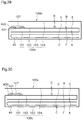
- Fig. 18 is a drawing which shows the front face (the side on which the name and address are printed) of the envelope sheet 100a used in this arrangement
- Fig. 19 is a drawing which shows the back side of the same.
- This envelope sheet 100a is a rectangular paper sheet including four paper pieces: a first paper piece 101, a second paper piece 102, a third paper piece 103, a fourth paper piece 104, which are connected by folds, and is formed into an envelope folded in four having the same shape as the external form of a sheet of the paper piece by folding in three portions.
- the front sides of the each piece of the envelope paper are denoted by the names A, B, C and D, respectively
- the back sides of the each piece of the envelope paper are denoted by the names E, F, G and H, respectively, for the convenience of explanation.
- the first paper piece 101 (A, E) is a portion which is folded inside of the envelope and becomes a content.
- the first paper piece 101 is provided with a perforation 220, and forms a return postcard by cutting off the perforation 220 after opening the envelope.
- the second paper piece 102 (B, F) is a portion which is folded inside of the envelope and becomes a content. Text, images and other objects can be printed, if necessary, on the front side and back side B, F of the second paper piece 102.
- the front side C of the third paper piece 103 corresponds to the front side of the envelope, on which the name and address are printed.
- Text, images and other objects can be printed, if necessary, on the back side G of the third paper piece 103, and the folded first paper piece 101 and the second paper piece 102 are stacked in the order stated thereon.
- the front side D of the fourth paper piece 104 corresponds to the back side of the envelope, on which the name, address, etc. of the sender, if necessary, are printed.
- Text, images and other objects can be printed on the back side H of the fourth paper piece 104, and this back side H is stacked on the front side B of the folded second paper piece 102.
- the content enclosed in the envelope is nipped between the back side G of the third paper piece 103 and the first paper piece 101 stacked thereon. As shown in Fig.
- the width of the content 40 is smaller than the interval between the pressure-sensitive adhesives 106 printed in both edge portions of the paper piece of the envelope sheet 100a. Moreover, the length in the direction perpendicular to the width of the content 40 is slightly less than the size of the same direction of the piece of the envelope sheet 100a, and by folding this for an appropriate number of times, a size which allows accommodation in the envelope formed from this envelope sheet 100a.
- the front side A of the first paper piece 101 and the front side B of the second paper piece 102 are provided with more than one portions of the pressure-sensitive adhesives 106 at a predetermined interval along both edge portions in the width direction.
- the front sides C and D of third paper side 103 and fourth paper side 104, respectively are provided with no pressure-sensitive adhesive.
- the back side E of the first paper piece 101 and the back side F of the second paper piece 102 are provided with the pressure-sensitive adhesives 106 along both edge portions in the width direction in a plurality of portion at predetermined intervals so as to be in positions different from those of the pressure-sensitive adhesives 106 of the front sides A and B.
- the back side G of the third paper piece 101 and the back side H of the fourth paper piece 102 are provided with the pressure-sensitive adhesives 106 along both edge portions in the width direction in the form of a continuous band. These pressure-sensitive adhesives 106 in the form of the continuous band are formed slightly beyond the back side F of the second paper piece 102.
- a pressure-sensitive adhesive exhibits adhesive strength by adhering pressure-sensitive adhesives provided on two sheets of paper together and applying a predetermined pressure. Its known examples include two-pack type adhesive using microcapsules and natural rubber-based adhesion materials, among others.
- the arrangement pattern of these pressure-sensitive adhesives 106 the pressure-sensitive adhesives 106 of corresponding paper pieces are considered to be in the same position and in contact with each other when the paper pieces are folded to be assembled in the form of an envelope.
- the envelope sheet 100a for example, are stacked in the same vertical positional relationship, e.g., with their front sides facing up, the pressure-sensitive adhesives 106 on the front sides and the pressure-sensitive adhesives 106 on the back sides do not face each other to avoid contact therebetween.
- remoistening pastes 107 are provided as another adhesive different from the pressure-sensitive adhesives in a band-shaped pattern along the width direction.
- the back side H of the fourth paper piece 102 is provided with an adhesive strength adjustment layer 400 inwardly of both edge portions in the width direction of the envelope and close to the side opposite to the fold of the third paper piece 103, in a band-shaped pattern along the width direction.
- the position in which the adhesive strength adjustment layer 400 is provided is a position facing the remoistening pastes 107 when this envelope sheet 100a is formed into an envelope. That is, when this envelope sheet 100a is formed into an envelope, the remoistening paste 107 is adhered to the fourth paper piece 104 via the adhesive strength adjustment layer 400.
- the remoistening paste is, for example, mucilage or the like, and has no adhesive strength when it is applied on paper and dried, but develops adhesive strength when wetted with water, and when the paper sheet is placed together with another paper sheet in this state and a required pressure is applied thereto, the two paper sheets are adhered.
- the pressure as in the case of adhering with a remoistening paste is effective even when it is significantly lower than the pressure required for a pressure-sensitive adhesive. Since their adhesive strengths are at least both considerably higher than that of paper, using two types of adhesives in a single envelope does not cause any problem due to a variation in the adhesive strength.
- an adhesive which does not normally have adhesive strength but develops adhesive strength by any operation other than the pressure as for the pressure-sensitive adhesive may be used.
- examples include adhesives which develop adhesive strength by heat, light including ultraviolet radiation, and other physical sections, other pressure-sensitive adhesives which develop adhesive strength with a pressure lower than that applied on the pressure-sensitive adhesive or double-faced adhesive tape and the like.
- the adhesive strength adjustment layer 400 may be silicon inks, waxes used for coating paper sheets, varnishes release properties, and other layers prepared from substances having low adhesiveness for various adhesives and having release properties.
- these substances and materials are collectively referred to as adhesion resistant materials.
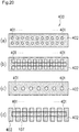
- the formation pattern of the adhesion resistant materials is, for example, as shown in Fig. 20 , that has adhesion resistant portions 402 in which the front side of the envelope sheet is covered with the adhesion resistant materials, and adhered portions 401 in which the front side of the envelope sheet is not covered with the adhesion resistant materials, and a plurality of adhered portions 401 in which the front side of the envelope sheet 100a is not covered with the adhesion resistant material is distributed predetermined shape and predetermined arrangement.
- Fig. 20(a) show a pattern in which the circular adhered portions 401 are disposed in two upper and lower rows at regular intervals;
- Fig. 20(b) shows a checker pattern in which square adhered portions are disposed in three rows alternately in the vertical direction;
- Fig. 20(c) shows a pattern in which adhered portions in the form of circles larger than those in Fig. 20(a) are disposed at regular intervals in a row.
- the adhered portions are surrounded by the adhesion resistant materials, but as in Fig. 20(d) , the following structure may also be employed: the adhesion resistant materials are formed of rectangular patterns disposed at predetermined intervals, the gaps between the rectangular patterns of the adhesion resistant materials form the adhered portions 401 where the front side of the envelope sheet 100a is exposed. Even if such a structure is employed, when the remoistening pastes 107 in the form of the continuous band exemplified in the figure are adhered, the remoistening paste 107 is adhered to the paper sheet in the adhered portions 401 which expose the paper sheet at constant intervals with a constant area.
- this adhesive strength adjustment layer 400 is a section which restricts the adhesion between the remoistening paste 107 and the envelope sheet 100a to a predetermined state and stabilizes the same, and therefore when both are caused to face and brought into contact, it is preferable that the formation area of the adhesive strength adjustment layer 400 includes the formation area of the remoistening paste 107, and is greater than this. That is, it is preferable that the remoistening paste 107 is adhered to the envelope sheet 100a only in the adhered portions of the adhesive strength adjustment layer 400, and is not adhered to the envelope sheet 100a irregularly outside the adhesive strength adjustment layer 400.
- the shapes, areas and arrangement patterns of the adhered portions 401 which are holes or gaps provided in the adhesion resistant materials where the front side of the envelope sheet 100a appears are determined to certain ones.
- the remoistening paste 107 is adhered to the envelope sheet 100a only through the adhered portions 401 of such patterns, and exerts almost no adhesive strength on the adhesion resistant materials of the adhesive strength adjustment layer 400.
- the above patterns of the adhered portions 401 in the adhesive strength adjustment layer 400 are determined as follows to simultaneously achieve two purposes which would be generally thought to contradict, that is, ease of opening of the envelope and ensuring the strength to withstand the external force applied during mailing or delivery.
- the adhesive strength of the remoistening paste 107 in each adhered portion 401 is set to a predetermined value lower than the strength of the envelope sheet 100a. Accordingly, in opening the sealing portion of the envelope sheet 100a by means of the remoistening paste 107 and adhered portions 401, if the paper sheet is opened in the width direction sequentially from the edge, the remoistening paste 107 adhered to the paper sheet through the adhered portions 401 is peeled off from the paper sheet without damaging the paper sheet, or even if a part of the front side of the paper sheet is peeled off, can be peeled off from the paper sheet without creating such damage that a hole is made in the paper sheet.
- the adhesive strength of the remoistening paste 107 in the adhered portions 401 is determined by the shape, size, disposition intervals and other conditions of the adhered portions 401 formed in the adhesive strength adjustment layer 400 when the type of the remoistening paste 107 is the same. Moreover, by performing the operation of peeling a number of dot-like adhered portions 401 having a constant adhesive strength sequentially and successively from the edge, the opener of the letter hears successive peeling sound of the adhered portions 401, and feels successive pleasing sense of opening at the fingertip, and therefore and he/she can confirm the certainty of opening by touch and ear. Accordingly, it is preferable that the arrangement pattern of the adhered portions 401 is regular since the above-described continuous peeling sound and the sense of opening can be obtained.
- the total adhesive strength of the remoistening paste 107 in all adhered portions 401 provided in the adhesive strength adjustment layer 400 is set to be greater than the external force possibly applied to the sealing portion of the envelope during mailing or delivery. This reduces the occurrence of the problem that the sealing portion of the envelope sheet 100a sealed by the remoistening paste 107 is opened by the external force applied during mailing or delivery.
- this envelope sheet 100a when the sealed envelope is opened, it can be opened without any significant damage the paper sheet with a small force, the information printed on the opened envelope sheet 100a is easy to read. Moreover, when the envelope has a return postcard or other object using a part of the envelope sheet 100a, no difficulty is found in its use. In addition, since the strength of the sealed portion by the remoistening paste 107 is set to be sufficient as a whole, accidental opening of the sealing portion sealed by the remoistening paste 107 by the external force during mailing and delivery of the envelope is unlikely to occur.
- the remoistening paste 107 is formed in the shape of two bands, and the adhesive strength adjustment layer 400 is formed in the shape of a single continuous band. Therefore, when opening the sealing portion of the envelope by these, the finger can be inserted from the gap of the paper sheet corresponding to the gap between the two bands of the remoistening paste 107 to open the adhered remoistening paste 107.
- the remoistening paste 107 can be peeled off successively and clearly from the edge with a small force due to the adhesive strength adjustment layer 400, and therefore the remoistening paste 107 is not necessarily formed in the form of two bands, and may be formed in the form of a single band as the adhesive strength adjustment layer 400.
- a peeling layer 405 is provided in a band-shaped pattern along the width direction in a position to the inside from both edge portions in the width direction of the envelope and close to the folding bordering the third paper piece 103.
- This peeling layer 405 is formed of the adhesion resistant materials the adhesive strength adjustment layer 400, but their functions and purposes are different.
- This peeling layer 405 has a positional relationship which faces the remoistening paste 107 on the other envelope sheet 100a when the envelope sheets 100a are stacked in the same vertical relationship.
- the remoistening paste 107 may be possibly adhered to the other the envelope sheet 100a depending on the conditions humidity and others.
- the peeling layer 405 if the remoistening paste 107 develops adhesiveness when a large number of the envelope sheets 100a are stacked, the paper sheets are not adhered to each other, and even if they are adhered, they can be easily peeled off without damaging the envelope sheet 100a.
- the first paper side 101 is bent to the back side of the envelope sheet 100a.
- the back side E of the first paper side 101 is stacked on the back side F of the second paper side 102, and the front side A of the first paper side 101 appears on the back side of the envelope sheet 100a.
- the content formed by folding is disposed on the front side A of the first paper side 101, and as shown by the arrow in Fig. 21 , the first paper side 101, second paper side 102 and content, are further bent onto the back side G of the third paper side 103. As a result, the state shown in Fig. 22 is formed.
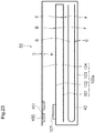
- the fourth paper side 104 is bend to the back side of the envelope sheet 100a as shown the arrow in Fig. 22 .
- the cross-sectional view of Fig. 23 schematically shows this state.
- the back side H of the fourth paper side 104 is stacked on the front side B of the second paper side 102, and the remoistening paste 107 of the second paper side 102 faces the adhesive strength adjustment layer 400 of the fourth paper side 104.
- the pressure-sensitive adhesives 106 on the paper pieces 101 to 104 face each other or come into contact with each other.
- the envelope sheet 100a is formed in the shape of an envelope folded in four in this state, but the pressure-sensitive adhesives 106 are not adhered yet. It should be noted that in Fig. 23 , the content 40 which is not illustrated in Figs. 21 and 22 is enclosed in the state of being folded in two.
- the entire surface of the envelope 50 is nipped by rollers not shown having a length equal to or greater than the width of the envelope to transfer the envelope 50, and the remoistening paste 107 of the second paper side 102 and the adhesive strength adjustment layer 400 of the fourth paper side 104 are adhered.
- the pressure-sensitive adhesives 106 placed in both edge portions in the width direction of the envelope 50 are adhered by the pressure rollers 80.
- a set of these pressure rollers 80 includes a set of upper and lower rollers, and two left and right pairs are provided.
- Both edge portions in the width direction of the envelope 50 enclosing the content 40, that is, the direction intersecting the transfer direction are nipped from above and below and pressurized to develop the adhesive strength of the pressure-sensitive adhesives 106 and achieve sealing. This causes the pressure-sensitive adhesives 106 which are in contact with each other between the paper pieces facing each other to develop tackiness, whereby the form of the envelope 50 sealing the content is realized.
- a fifth ink jet device S which is a printing section capable of discharging silicon ink which is an adhesion resistant material is provided next to the four ink jet devices C, K, M and Y.
- this ink jet device S it is possible to print the adhesive strength adjustment layer 400 on the envelope sheet in a desired pattern, and print the peeling layer 405 thereon.
- the enclosing and sealing section of this arrangement has substantially the same mechanical configuration as the enclosing and sealing section of the first arrangement, but has a different action or control by the control section 90 provided in the printing unit 2.
- the outline of the actions or controls different from those in the first arrangement will be also described in this paragraph for describing the configuration. It should be noted that the detail of the actions or controls will be described later.
- the envelope sheet 100a which is folded once by the main folding roller A', the first folding roller B' and other components which are the first folding section stands by where it has passed between the main folding roller A" and paper transport roller D", which are the second folding section, the content 40 transferred along the path 26, which is another second paper path 20 is aligned with the envelope sheet 100 a during standby, and further passes between the main folding roller A" and second folding roller B" to be provided with the second folding.
- the aligned envelope sheet 100a and content 40 are further forwarded by the main folding roller A" and second folding roller B".
- the envelope sheet 100a is in such a state that the front side B of the second paper piece 102 faces down, and the remoistening paste 107 faces the water-absorbing portion 62 of the moistening section 60.
- This state is close to, in Fig. 22 , the state that the fourth paper piece 104 is not yet folded in the direction of the arrow, and the surface B of the second paper side 102 is faced down.
- the rotation cam 64 operates to swing the swing arm 63, so that the remoistening paste 107 is pressed against the water-absorbing portion 62 to be moistened.
- the envelope sheet 100a is forwarded by the main folding roller A" and second folding roller C". Accordingly, the fourth paper piece 104 is folded, and the back side H of the fourth paper piece 104 is stacked on the front side B of the second paper piece 102, so that the remoistening paste 107 and adhesive strength adjustment layer 400 are adhered.
- the envelope sheet 100a is transferred from a paper feed rack P1.
- the envelope sheet 100a may be on any of the paper feed racks P1 to P4 of the printing unit 2.
- This envelope sheet 100a is printed on both sides by the ink jet devices C, K, M and Y during a single pass around the looped transfer path 5. Not only duplex printing but also simplex printing can be selected.
- name, address and other information are printed on the face which serves as the outer face of the envelope 50, while any information to be sent to the address, if necessary, is printed on the face which serves as the inner face of the envelope 50, along with particulars of the enclosed content 40.
- the information printed on the inner face of the envelope 50 can be read by a receiver by cutting and opening the envelope 50.
- printing on the adhesive strength adjustment layer 400 and the peeling layer 405 by silicon ink using the ink jet device S may be performed before or after the printing step by the ink jet devices C, K, M and Y.
- the envelope sheet 100a is transferred from the path 11, which is one of the first paper paths 10, by switching of a switching flap not shown to the folding section.
- the envelope sheet 100a is forwarded by the main folding roller A' and the paper transport roller D', impinges on an impinging member not shown to be warped, enters in between the main folding roller A' and the first folding roller B' from the warped portion, and further nipped and transferred to be provided with a fold in a portion of the front end portion thereof in the paper feed direction.
- the unfinished envelope which is partially folded stands by for the alignment with the content 40 in a position where it has passed between the main folding roller A" and paper transport roller D" of the enclosing and sealing section. After the alignment of the content 40, the envelope is further passed between the main folding roller A" and second folding roller B" and provided with the second folding while wrapping up the content 40, the state shown in Fig. 5 is almost formed, although the content is not shown.
- a required paper sheet 30 is transferred as the content 40 from any of the paper feed racks P2 to P4 into the looped transfer path 5 at a certain determined interval, and both sides of the paper sheet 30 are printed by the ink jet devices C, K, M and Y during a single pass through this transfer path. Not only duplex printing but also simplex printing can be selected.
- the paper sheet 30 of the content 40 is transferred to the path 21, which is one of the second paper paths 20 by switching of a switching flap not shown.
- the paper sheet 30 is retained at an alignment portion 23 on the path 21, which is one of the second paper paths 20 until a required number of sheets are accumulated, and the alignment portion 23 opens when the required number is accumulated and the sheets are transferred into the folding section (main folding roller A, etc.).
- the folding section By a plurality of folding performed by the folding section, the paper sheet 30 folded in a desired state is transferred into the enclosing and sealing unit (main folding roller A", etc.) via the path 26, which is the other path of the second paper paths 20.
- the content 40 is folded inwardly in three (in the example shown in Fig. 23 , a content folded in two is shown as another example). This content 40 is aligned with the envelope sheet 100a in the process of being folded standing by in a position where it has passed between the main folding roller A" and paper transport roller D".
- the aligned envelope sheet 100a and content 40 are further forwarded by the main folding roller A" and second folding roller B" to be provided with the second folding, whereby the content 40 is wrapped up in the envelope sheet 100a.
- the rotation cam 64 of the moistening section 60 is activated to swing the swing arm 63, and the remoistening paste 107 of the envelope sheet 100a is pressed against the water-absorbing portion 62 to be moistened.
- the envelope sheet 100a is forwarded by the main folding roller A" and second folding roller C", the fourth paper piece 104 is folded, the adhesive strength adjustment layer 400 on the back side H of the fourth paper piece 104 is adhered with the remoistening paste 107 on the front side B of the second paper piece 102 to be in the shape of the envelope 50, and the envelope enters in between the positioning rollers 65.
- the positioning rollers 65 nipping the envelope 50 adjusts the position of the envelope 50 in the axial direction based on the position of the envelope 50 captured by the edge sensor 66 shown in Fig. 12 , and the envelope 50 is moved to bring the pressure-sensitive adhesives 106 on the envelope 50 to a position overlapping the pressure rollers 80.
- both edge portions of the envelope 50 are stuck together as it passes through the pressure rollers 80, whereby sealing of the envelope 50 is performed.
- the paper pieces are adhered to each other with the remoistening paste 107 first, the positioning of the envelope 50 in the width direction is accurately performed and is then transferred in between the pressure rollers 80, so that the pressure-sensitive adhesives 106 are pressurized securely by the pressure rollers 80 having a small width. Therefore, the pressure-sensitive adhesives 106 can be securely adhered by the pressure rollers 80 which can produce a high pressure with a small force having a small width and with a width sufficient for adhesion.
- the finished sealed letter after the completion of enclosing and sealing is discharged into a discharge tray 48 provided on the top surface of the cabinet 9, where it is sequentially stacked up to be taken out later.
- the envelope sheet 100a of this arrangement for producing an envelope by folding is designed to allow adhesion of both edges in the direction the width of the envelope with the pressure-sensitive adhesive 106, and the adhesion of a portion inside the pressure-sensitive adhesive 106 with the remoistening paste 107, but the adhesive strength adjustment layer 400 including a number of adhesion portions 401 from which the surface of the paper sheet are exposed regularly is configured of the adhesion resistant materials on the surface of the target paper sheet adhered by the remoistening paste 107.
- the adhesive strength at each point of these adhered portions 401 is set to a certain value which is lower than the breakage strength of the paper sheet, and therefore if the adhered portions are peeled off sequentially from one side, the envelope can be easily opened with a certain force. Moreover, the response felt on the hand in opening the envelope is constant, and therefore a stable and favorable sense can be obtained. Moreover, even if the adhesive strength for each point of the adhered portions 401 is small, a necessary number of adhered portions 401 are provided to set the adhesive strength as a whole as high as necessary as a whole, and therefore accidental peeling of the sealing portion of the remoistening paste 107 by a load applied during mailing or delivery can be surely prevented.
- the remoistening paste 107 is generally formed by a step of applying in a stamping manner using a sponge-like projection component, it is difficult to form the same in the form of small dots, and even if it can be formed in the form of dots, it is even more difficult to form a paste having high viscosity in the form of dots with stable diameter, and therefore it has been actually impossible to adjust the adhesive strength in controlling of the application pattern of the remoistening paste 107.
- the remoistening paste 107 is formed in the shape of a uniform band, and a pattern in which a number of holes in the form of dots is formed is printed using the adhesion resistant materials on the surface of the paper sheet facing this, point adhesion with a stable small diameter by the remoistening paste 107 can be realized, and ease of opening and unlikeliness of accidental opening during mailing and the like can be both realized.
- the envelope sheet 100a of this arrangement has such a configuration that the adhesive 107 and the adhesive strength adjustment layer 400 are provided in different positions of the envelope sheet 100a, and it therefore has such effects that it is not necessary to set the accuracy of positioning to a high level compared to the case where the adhesive 107 and adhesive strength adjustment layer 400 are formed to be stacked in the same position on the envelope sheet 100, and that the production is easy.
- the remoistening paste 107 is provided on the front side B of the second paper side 102
- the adhesive strength adjustment layer 400 is provided on the back side H of the fourth paper side 104
- the remoistening paste 107 and adhesive strength adjustment layer 400 face each other to be adhered to each other when the envelope sheet 100a is folded into the shape of the envelope 50.
- the remoistening paste 107 and adhesive strength adjustment layer 400 are not necessarily formed separately on different paper sheets, but can be configured as in the third arrangement shown in Fig. 29 . That is, in this example, the adhesive strength adjustment layer 400 having a number of adhered portions 401 (holes) is provided on the front side B of the second paper side 102, the remoistening paste 107 is provided in a range smaller than the adhesive strength adjustment layer 400 thereon, and the remoistening paste 107 is adhered to the second paper side 102 in advance by causing the remoistening paste 107 to enter the adhered portions 401.
- the fourth paper piece 104 is adhered to the remoistening paste 107 in a large area, but the adhesive strength between the remoistening paste 107 and the second paper side 102 is as defined by the adhesive strength adjustment layer 400, and is lower than the adhesive strength between the fourth paper piece 104 and the remoistening paste 107. Therefore, in opening the envelope, the fourth paper side 104 on which the remoistening paste 107 is deposited can be peeled off from the second paper piece 102 with a small constant force.
- both the remoistening paste 107 and adhesive strength adjustment layer 400 can be stacked and formed in an approximately identical position on the same paper piece, and therefore it is possible to reserve a greater area of a region where the printed information can be read more easily.
- the remoistening paste 107 is moistened when used, and develops the adhesive strength by drying and shrinking after being adhered to the paper sheet, but the influence of this drying and shrinking may deform the paper in some cases.
- the remoistening paste 107 is provided on of the adhesive strength adjustment layer 400 even partially, and therefore the remoistening paste 107 slides on the adhesive strength adjustment layer 400 when it dries and shrinks. This reduces the force applied to the paper sheet, whereby the effect in reducing the deformation of the paper sheet can be obtained.
- the remoistening paste 107 is provided on the front side B of the second paper side 102, and the adhesive strength adjustment layer 400 having a number of adhered portions 401 (holes) is provided thereon to cover the remoistening paste 107.
- the envelope sheet 100c is folded and formed into the shape of an envelope in this state, and the fourth paper piece 104 is adhered to the remoistening paste 107 through the adhered portions 401 of the adhesive strength adjustment layer 400. Therefore, in opening, the fourth paper side 104 can be peeled off with a small constant force from the second paper piece 102 on which the remoistening paste 107 covered with the adhesive strength adjustment layer 400 is provided.
- both the remoistening paste 107 and the adhesive strength adjustment layer 400 can be formed on the same paper piece, and therefore the area of a region where the printed information can be read more easily can be increased.
- the sealed letter producing device of the first arrangement including the ink jet device S which discharges the silicon ink, silicon ink is printed on the remoistening paste 107 which has been applied to the envelope sheet 100c in necessary positions in advance to form the adhesive strength adjustment layer 400 by printing the silicon ink on the remoistening paste 107, whereby the envelope sheet of this arrangement can be formed.
- the sealed letter producing device 1 of each of the arrangements and embodiment described above is provided with the printing unit 2, but this printing unit 2 may be an existing image forming device. That is, the sealed letter producing device 1 can be formed by using a normal image forming device already installed in places of business and other places as the printing unit 2, and connecting the enclosing and sealing unit 3 to this. Accordingly, printing of the envelope sheets 100, 100a, 100b, 100c, 200 and the content 40 can be performed by using a single existing image forming device, which would save the installation cost of the automatic sealed letter producing device.
- the paper sheet 30 of the content 40 is not necessarily folded, and may be enclosed in the envelope in its original size without being folded depending on its relationship with the size of the envelope.
- the sheet-like paper sheet is used as the paper sheet 30 of the envelope paper sheets 100, 100a, 100b, 100c, 200 and the content 40, but, for example, a paper roll may be used, and may be cut and provided in a required length when it is used.
Landscapes
- Engineering & Computer Science (AREA)
- Mechanical Engineering (AREA)
- Physics & Mathematics (AREA)
- General Physics & Mathematics (AREA)
- Making Paper Articles (AREA)
- Credit Cards Or The Like (AREA)
- Packaging Of Special Articles (AREA)
- Package Closures (AREA)
Claims (2)
- Feuille d'enveloppe (200), appliquée à un dispositif de production de lettres scellées (1) comprenant une unité de mise sous enveloppe et de fermeture (3) qui produit une lettre scellée par mise sous enveloppe et par scellement d'un contenu (40) par pliage d'une feuille d'enveloppe (200) d'une manière permettant d'enfermer le contenu (40), ladite feuille d'enveloppe (200) comprenant deux plis qui sont parallèles à une direction de largeur de la feuille d'enveloppe (200) divisant la feuille en un premier (201), en un deuxième (202) et en un troisième (203) pli de papier, les premier (201), deuxième (202) et troisième (203) plis de papier ayant une même longueur dans la direction de la largeur, le contenu (40) étant placé entre les deuxième (202) et troisième (203) plis de papier, ladite feuille d'enveloppe comprenant un côté recto et un côté verso, la feuille d'enveloppe (200) comportant des adhésifs sensibles à la pression (306) appliqués dans les deux parties de bord du premier (201), du deuxième (202) et du troisième (203) pli de papier dans la direction de la largeur, lesdits adhésifs sensibles à la pression (306) n'étant appliqués que d'un seul côté entre le recto et le verso dans les deux parties de bord dans la direction de sa largeur et quand ils sont courbés, les premier (201) et troisième (203) plis de papier sont collés, les troisième (203) et deuxième (202) plis de papier sont collés, et le troisième pli de papier devient un pli de papier intérieur quand il est courbé, le troisième pli de papier (203) maintenant le contenu (40) tandis qu'il est intercalé entre les premier (201) et deuxième (202) plis de papier, la feuille d'enveloppe comprenant en outre des encoches (205) qui se trouvent dans les deux parties de bord du troisième pli de papier (203) de la feuille et une partie des adhésifs sensibles à la pression (306) du deuxième pli de papier (202) exposé à partir des encoches (205) dans le troisième pli de papier (203) adhérant à une partie des adhésifs sensibles à la pression (306) du premier pli de papier (201), moyennant quoi on obtient l'adhésion des premier (201) et deuxième (202) plis de papier intercalant le troisième pli de papier (203).
- Feuille d'enveloppe (200) selon la revendication 1, comprenant en outre une colle à timbres-poste (307) appliquée sur le troisième (203) pli de papier.
Applications Claiming Priority (4)
| Application Number | Priority Date | Filing Date | Title |
|---|---|---|---|
| JP2010239789A JP5721394B2 (ja) | 2010-10-26 | 2010-10-26 | 封書作成装置及び封筒用紙 |
| JP2011212814A JP2013071759A (ja) | 2011-09-28 | 2011-09-28 | 封筒用紙及び封書作成装置 |
| EP11836335.7A EP2633990B1 (fr) | 2010-10-26 | 2011-10-26 | Dispositif de préparation de lettre cachetée et papier d'enveloppe |
| PCT/JP2011/074667 WO2012057202A1 (fr) | 2010-10-26 | 2011-10-26 | Dispositif de préparation de lettre cachetée et papier d'enveloppe |
Related Parent Applications (2)
| Application Number | Title | Priority Date | Filing Date |
|---|---|---|---|
| EP11836335.7A Division EP2633990B1 (fr) | 2010-10-26 | 2011-10-26 | Dispositif de préparation de lettre cachetée et papier d'enveloppe |
| EP11836335.7A Division-Into EP2633990B1 (fr) | 2010-10-26 | 2011-10-26 | Dispositif de préparation de lettre cachetée et papier d'enveloppe |
Publications (2)
| Publication Number | Publication Date |
|---|---|
| EP3015259A1 EP3015259A1 (fr) | 2016-05-04 |
| EP3015259B1 true EP3015259B1 (fr) | 2019-01-30 |
Family
ID=45993908
Family Applications (2)
| Application Number | Title | Priority Date | Filing Date |
|---|---|---|---|
| EP11836335.7A Not-in-force EP2633990B1 (fr) | 2010-10-26 | 2011-10-26 | Dispositif de préparation de lettre cachetée et papier d'enveloppe |
| EP15194168.9A Not-in-force EP3015259B1 (fr) | 2010-10-26 | 2011-10-26 | Papier d'enveloppe |
Family Applications Before (1)
| Application Number | Title | Priority Date | Filing Date |
|---|---|---|---|
| EP11836335.7A Not-in-force EP2633990B1 (fr) | 2010-10-26 | 2011-10-26 | Dispositif de préparation de lettre cachetée et papier d'enveloppe |
Country Status (4)
| Country | Link |
|---|---|
| US (1) | US9833965B2 (fr) |
| EP (2) | EP2633990B1 (fr) |
| CN (1) | CN103167951B (fr) |
| WO (1) | WO2012057202A1 (fr) |
Families Citing this family (14)
| Publication number | Priority date | Publication date | Assignee | Title |
|---|---|---|---|---|
| DE102007054714B4 (de) * | 2007-11-14 | 2016-09-22 | Windmöller & Hölscher Kg | Vorrichtung und Verfahren zur Herstellung eines Beutels aus Papier sowie Papierbeutel |
| JP5893243B2 (ja) * | 2010-09-17 | 2016-03-23 | 理想科学工業株式会社 | 封書作成装置 |
| EP2633990B1 (fr) * | 2010-10-26 | 2018-01-03 | Riso Kagaku Corporation | Dispositif de préparation de lettre cachetée et papier d'enveloppe |
| JP5960446B2 (ja) * | 2012-02-23 | 2016-08-02 | 理想科学工業株式会社 | 封入封緘システム |
| JP5841105B2 (ja) * | 2013-08-30 | 2016-01-13 | 株式会社東芝 | シート後処理装置 |
| JP2015081988A (ja) * | 2013-10-22 | 2015-04-27 | 株式会社沖データ | 画像形成装置及び画像形成方法 |
| JP2016030336A (ja) * | 2014-07-25 | 2016-03-07 | 理想科学工業株式会社 | 印刷装置 |
| JP6090702B1 (ja) * | 2016-06-27 | 2017-03-08 | 株式会社オカザキ | 封筒加工装置 |
| JP2018016323A (ja) * | 2016-07-25 | 2018-02-01 | 理想科学工業株式会社 | シート状物 |
| US20190160856A1 (en) * | 2017-11-30 | 2019-05-30 | Bell And Howell, Llc | Methods and systems to create a mailpiece with an inline buckle folder |
| US11718435B2 (en) * | 2019-04-03 | 2023-08-08 | Westrock Shared Services, Llc | Pack to pouch systems |
| JP7515337B2 (ja) * | 2020-07-31 | 2024-07-12 | キヤノン株式会社 | 接着装置 |
| JP7693465B2 (ja) * | 2021-08-30 | 2025-06-17 | キヤノン株式会社 | 画像形成システム |
| JP2023118558A (ja) * | 2022-02-15 | 2023-08-25 | 株式会社リコー | 封入装置、封入封緘装置及び画像形成システム |
Family Cites Families (37)
| Publication number | Priority date | Publication date | Assignee | Title |
|---|---|---|---|---|
| US4202150A (en) | 1973-05-25 | 1980-05-13 | Ab Sture Ljungdahl | Device for producing envelopes in a continuous operation |
| SE382589B (sv) * | 1973-05-25 | 1976-02-09 | Ljungdahl Sture Ab | Anordning for kuvertering av inlagor med hjelp av valsar |
| US4787192A (en) * | 1985-06-24 | 1988-11-29 | Gunther International, Ltd. | Mechanism for folding an envelope around an insert |
| US4951864A (en) * | 1986-12-16 | 1990-08-28 | Transkrit Corporation | One-piece mailer and apparatus for folding same |
| US4972655A (en) | 1987-06-30 | 1990-11-27 | Iseto Shiko Co., Ltd. | Apparatus for manufacturing sealed postal mails or the like envelope assemblies |
| JP2521498B2 (ja) | 1987-10-30 | 1996-08-07 | トッパン・ムーア株式会社 | 封書の作成方法 |
| JP3491921B2 (ja) | 1993-03-12 | 2004-02-03 | 大日本印刷株式会社 | 製袋フォーム |
| US5568717A (en) * | 1993-03-30 | 1996-10-29 | Moore Business Forms, Inc. | Forming an envelope around inserts |
| GB2284794B (en) * | 1993-12-20 | 1998-03-04 | Pitney Bowes Plc | Inserter machine for stuffing envelopes |
| JP3343165B2 (ja) | 1994-02-21 | 2002-11-11 | トッパン・フォームズ株式会社 | カード送付用台紙及びこの台紙を用いたカード送付用具 |
| US5560185A (en) * | 1995-04-20 | 1996-10-01 | Glenn Petkovsek | System and method for sealing a flapless envelope |
| US5785242A (en) * | 1996-07-31 | 1998-07-28 | Moore Business Forms, Inc. | Pressure seal spot pattern for C-fold mailer |
| US5702098A (en) * | 1996-10-18 | 1997-12-30 | Pitney Bowes Inc. | Envelope closing and sealing apparatus |
| EP0838330A3 (fr) * | 1996-10-23 | 1999-02-24 | BIELOMATIK LEUZE GmbH + Co. | Méthode et dispositif de fabrication de pli, comme un pli postal ainsi que ce pli |
| CN1237527A (zh) * | 1998-06-01 | 1999-12-08 | 邹东时 | 方便信封 |
| US6179952B1 (en) * | 1998-09-18 | 2001-01-30 | Moore U.S.A. Inc. | Pressure sealer three tiered sealing roll configuration |
| US6162316A (en) | 1998-11-04 | 2000-12-19 | Privatizer Systems, Inc. | Mailer form for use in a folder-sealer device |
| US6149752A (en) * | 1998-11-04 | 2000-11-21 | Privatizer Systems, Inc. | Apparatus and method for folding and sealing a mailer form having pressure sensitive adhesive positioned thereon |
| US6019280A (en) * | 1998-12-31 | 2000-02-01 | Moore U.S.A. Inc. | C-fold return postcard mailer |
| US6196453B1 (en) * | 2000-01-18 | 2001-03-06 | Moore North America, Inc. | Two way mailer for simple sealer |
| JP2001322377A (ja) | 2000-05-18 | 2001-11-20 | Dainippon Printing Co Ltd | メールフォーム |
| US6939627B2 (en) * | 2000-07-13 | 2005-09-06 | Dai Nippon Printing Co., Ltd. | Scratch layer transfer sheet and method of producing scratch printing product |
| US20020170681A1 (en) * | 2001-02-23 | 2002-11-21 | Alain Saurer | Letter moistener |
| US7000364B2 (en) * | 2001-10-19 | 2006-02-21 | Bowe Bell + Howell Company | Apparatus and method for stuffing a folder |
| JP4623632B2 (ja) * | 2004-09-16 | 2011-02-02 | 株式会社フジシールインターナショナル | 筒状フィルムの製造装置 |
| US7231750B2 (en) * | 2005-02-18 | 2007-06-19 | Pitney Bowes Inc. | Method and system for creating mailpieces from a single continuous web of printed material |
| US7254931B2 (en) * | 2005-02-18 | 2007-08-14 | Pitney Bowes Inc. | Method and system for creating mailpieces from a single continuous web of printed material |
| US7357080B2 (en) | 2005-02-18 | 2008-04-15 | Pitney Bowes Inc. | Method for creating a single continuous web from which to fabricate mailpieces |
| JP4684723B2 (ja) | 2005-03-04 | 2011-05-18 | 大日本印刷株式会社 | 情報保護シート |
| FR2888774A1 (fr) * | 2005-07-25 | 2007-01-26 | Megaspirea Production Soc Par | Procede de fabrication de plis courriers et machine mettant en oeuvre ledit procede |
| US7398635B2 (en) * | 2006-01-11 | 2008-07-15 | Pitney Bowes Inc. | Method and device for aligning a receiving envelope in a mail inserter |
| GB0625656D0 (en) * | 2006-12-21 | 2007-01-31 | Pitney Bowes Ltd | Movable sealer |
| US8701977B2 (en) * | 2007-03-02 | 2014-04-22 | 7R Communications, Llc | Cards integrated into a one-way or two-way mailer for multiple uses |
| US7871215B2 (en) * | 2007-08-02 | 2011-01-18 | Pitney Bowes Inc. | Reconfigurable mailing machine for printing and opening mailpieces |
| US20090107086A1 (en) * | 2007-10-30 | 2009-04-30 | Keane Joseph J | System for integrated production of envelopes and contents thereof |
| ITRM20080030A1 (it) * | 2008-01-21 | 2009-07-22 | Kern Sistemi S R L | Metodo e dispositivo per generare elementi postali |
| EP2633990B1 (fr) * | 2010-10-26 | 2018-01-03 | Riso Kagaku Corporation | Dispositif de préparation de lettre cachetée et papier d'enveloppe |
-
2011
- 2011-10-26 EP EP11836335.7A patent/EP2633990B1/fr not_active Not-in-force
- 2011-10-26 US US13/881,485 patent/US9833965B2/en active Active
- 2011-10-26 EP EP15194168.9A patent/EP3015259B1/fr not_active Not-in-force
- 2011-10-26 CN CN201180051923.4A patent/CN103167951B/zh active Active
- 2011-10-26 WO PCT/JP2011/074667 patent/WO2012057202A1/fr not_active Ceased
Non-Patent Citations (1)
| Title |
|---|
| None * |
Also Published As
| Publication number | Publication date |
|---|---|
| EP2633990A1 (fr) | 2013-09-04 |
| CN103167951B (zh) | 2015-08-26 |
| EP3015259A1 (fr) | 2016-05-04 |
| EP2633990B1 (fr) | 2018-01-03 |
| US20130260977A1 (en) | 2013-10-03 |
| US9833965B2 (en) | 2017-12-05 |
| WO2012057202A1 (fr) | 2012-05-03 |
| EP2633990A4 (fr) | 2014-08-13 |
| CN103167951A (zh) | 2013-06-19 |
Similar Documents
| Publication | Publication Date | Title |
|---|---|---|
| EP3015259B1 (fr) | Papier d'enveloppe | |
| CA1245445A (fr) | Etiquettes, et leur fabrication | |
| JP6015918B2 (ja) | 多層折情報通信体の製造方法 | |
| CZ41999A3 (cs) | Samolepivá etiketa | |
| JP5721394B2 (ja) | 封書作成装置及び封筒用紙 | |
| JP5828585B2 (ja) | 水濡れに強い情報通信体及びその製造方法 | |
| JP5831831B2 (ja) | ラミネータの任意位置自動停止手段及びそれを用いた長尺状の印刷紙のラミネート方法並びにそれを用いた情報通信体の製造方法 | |
| JP3807723B2 (ja) | 隠蔽ラベル剥離装置 | |
| JP2013071759A (ja) | 封筒用紙及び封書作成装置 | |
| JP4704431B2 (ja) | 自己接着ラベルの製造方法 | |
| JP5737497B2 (ja) | 圧着装置 | |
| JPH0345258Y2 (fr) | ||
| EP1584487A2 (fr) | Formulaire | |
| JPH0330997A (ja) | カード送付体 | |
| JP4711431B2 (ja) | 隠蔽ラベル剥離装置 | |
| KR930003345B1 (ko) | 엽서 및 그것에 사용하는 연속용지 | |
| JPH04250030A (ja) | 封書素材及び封書作成方法 | |
| JP4854082B2 (ja) | 隠蔽ラベル剥離装置 | |
| JP4397281B2 (ja) | 組伝票製造装置およびこれにより作製される組伝票 | |
| JPH09267966A (ja) | 連続用紙処理装置 | |
| JP2000052452A (ja) | 薬袋印字装置に使用する専用薬袋の製造方法 | |
| JPH0314457A (ja) | 貼着袋体 | |
| US20090047460A1 (en) | Adhesive dispensing product | |
| JP2016172430A (ja) | 水濡れに強い情報通信体の製造方法 | |
| JP2013240901A (ja) | ポストカードの製造方法 |
Legal Events
| Date | Code | Title | Description |
|---|---|---|---|
| PUAI | Public reference made under article 153(3) epc to a published international application that has entered the european phase |
Free format text: ORIGINAL CODE: 0009012 |
|
| AC | Divisional application: reference to earlier application |
Ref document number: 2633990 Country of ref document: EP Kind code of ref document: P |
|
| AK | Designated contracting states |
Kind code of ref document: A1 Designated state(s): AL AT BE BG CH CY CZ DE DK EE ES FI FR GB GR HR HU IE IS IT LI LT LU LV MC MK MT NL NO PL PT RO RS SE SI SK SM TR |
|
| STAA | Information on the status of an ep patent application or granted ep patent |
Free format text: STATUS: REQUEST FOR EXAMINATION WAS MADE |
|
| 17P | Request for examination filed |
Effective date: 20161104 |
|
| RBV | Designated contracting states (corrected) |
Designated state(s): AL AT BE BG CH CY CZ DE DK EE ES FI FR GB GR HR HU IE IS IT LI LT LU LV MC MK MT NL NO PL PT RO RS SE SI SK SM TR |
|
| STAA | Information on the status of an ep patent application or granted ep patent |
Free format text: STATUS: EXAMINATION IS IN PROGRESS |
|
| 17Q | First examination report despatched |
Effective date: 20171027 |
|
| REG | Reference to a national code |
Ref country code: DE Ref legal event code: R079 Ref document number: 602011056128 Country of ref document: DE Free format text: PREVIOUS MAIN CLASS: B31B0021600000 Ipc: B42D0015080000 |
|
| RIC1 | Information provided on ipc code assigned before grant |
Ipc: B43M 5/04 20060101ALI20180801BHEP Ipc: B42D 15/08 20060101AFI20180801BHEP Ipc: B43M 3/04 20060101ALI20180801BHEP Ipc: B65D 27/16 20060101ALI20180801BHEP Ipc: B65D 27/10 20060101ALI20180801BHEP |
|
| GRAP | Despatch of communication of intention to grant a patent |
Free format text: ORIGINAL CODE: EPIDOSNIGR1 |
|
| STAA | Information on the status of an ep patent application or granted ep patent |
Free format text: STATUS: GRANT OF PATENT IS INTENDED |
|
| INTG | Intention to grant announced |
Effective date: 20180913 |
|
| GRAS | Grant fee paid |
Free format text: ORIGINAL CODE: EPIDOSNIGR3 |
|
| GRAA | (expected) grant |
Free format text: ORIGINAL CODE: 0009210 |
|
| STAA | Information on the status of an ep patent application or granted ep patent |
Free format text: STATUS: THE PATENT HAS BEEN GRANTED |
|
| AC | Divisional application: reference to earlier application |
Ref document number: 2633990 Country of ref document: EP Kind code of ref document: P |
|
| AK | Designated contracting states |
Kind code of ref document: B1 Designated state(s): AL AT BE BG CH CY CZ DE DK EE ES FI FR GB GR HR HU IE IS IT LI LT LU LV MC MK MT NL NO PL PT RO RS SE SI SK SM TR |
|
| REG | Reference to a national code |
Ref country code: GB Ref legal event code: FG4D |
|
| REG | Reference to a national code |
Ref country code: CH Ref legal event code: EP |
|
| REG | Reference to a national code |
Ref country code: AT Ref legal event code: REF Ref document number: 1092933 Country of ref document: AT Kind code of ref document: T Effective date: 20190215 |
|
| REG | Reference to a national code |
Ref country code: IE Ref legal event code: FG4D |
|
| REG | Reference to a national code |
Ref country code: DE Ref legal event code: R096 Ref document number: 602011056128 Country of ref document: DE |
|
| REG | Reference to a national code |
Ref country code: LT Ref legal event code: MG4D |
|
| REG | Reference to a national code |
Ref country code: NL Ref legal event code: MP Effective date: 20190130 |
|
| PG25 | Lapsed in a contracting state [announced via postgrant information from national office to epo] |
Ref country code: PL Free format text: LAPSE BECAUSE OF FAILURE TO SUBMIT A TRANSLATION OF THE DESCRIPTION OR TO PAY THE FEE WITHIN THE PRESCRIBED TIME-LIMIT Effective date: 20190130 Ref country code: LT Free format text: LAPSE BECAUSE OF FAILURE TO SUBMIT A TRANSLATION OF THE DESCRIPTION OR TO PAY THE FEE WITHIN THE PRESCRIBED TIME-LIMIT Effective date: 20190130 Ref country code: FI Free format text: LAPSE BECAUSE OF FAILURE TO SUBMIT A TRANSLATION OF THE DESCRIPTION OR TO PAY THE FEE WITHIN THE PRESCRIBED TIME-LIMIT Effective date: 20190130 Ref country code: NL Free format text: LAPSE BECAUSE OF FAILURE TO SUBMIT A TRANSLATION OF THE DESCRIPTION OR TO PAY THE FEE WITHIN THE PRESCRIBED TIME-LIMIT Effective date: 20190130 Ref country code: ES Free format text: LAPSE BECAUSE OF FAILURE TO SUBMIT A TRANSLATION OF THE DESCRIPTION OR TO PAY THE FEE WITHIN THE PRESCRIBED TIME-LIMIT Effective date: 20190130 Ref country code: SE Free format text: LAPSE BECAUSE OF FAILURE TO SUBMIT A TRANSLATION OF THE DESCRIPTION OR TO PAY THE FEE WITHIN THE PRESCRIBED TIME-LIMIT Effective date: 20190130 Ref country code: PT Free format text: LAPSE BECAUSE OF FAILURE TO SUBMIT A TRANSLATION OF THE DESCRIPTION OR TO PAY THE FEE WITHIN THE PRESCRIBED TIME-LIMIT Effective date: 20190530 Ref country code: NO Free format text: LAPSE BECAUSE OF FAILURE TO SUBMIT A TRANSLATION OF THE DESCRIPTION OR TO PAY THE FEE WITHIN THE PRESCRIBED TIME-LIMIT Effective date: 20190430 |
|
| REG | Reference to a national code |
Ref country code: AT Ref legal event code: MK05 Ref document number: 1092933 Country of ref document: AT Kind code of ref document: T Effective date: 20190130 |
|
| PG25 | Lapsed in a contracting state [announced via postgrant information from national office to epo] |
Ref country code: GR Free format text: LAPSE BECAUSE OF FAILURE TO SUBMIT A TRANSLATION OF THE DESCRIPTION OR TO PAY THE FEE WITHIN THE PRESCRIBED TIME-LIMIT Effective date: 20190501 Ref country code: RS Free format text: LAPSE BECAUSE OF FAILURE TO SUBMIT A TRANSLATION OF THE DESCRIPTION OR TO PAY THE FEE WITHIN THE PRESCRIBED TIME-LIMIT Effective date: 20190130 Ref country code: HR Free format text: LAPSE BECAUSE OF FAILURE TO SUBMIT A TRANSLATION OF THE DESCRIPTION OR TO PAY THE FEE WITHIN THE PRESCRIBED TIME-LIMIT Effective date: 20190130 Ref country code: LV Free format text: LAPSE BECAUSE OF FAILURE TO SUBMIT A TRANSLATION OF THE DESCRIPTION OR TO PAY THE FEE WITHIN THE PRESCRIBED TIME-LIMIT Effective date: 20190130 Ref country code: IS Free format text: LAPSE BECAUSE OF FAILURE TO SUBMIT A TRANSLATION OF THE DESCRIPTION OR TO PAY THE FEE WITHIN THE PRESCRIBED TIME-LIMIT Effective date: 20190530 Ref country code: BG Free format text: LAPSE BECAUSE OF FAILURE TO SUBMIT A TRANSLATION OF THE DESCRIPTION OR TO PAY THE FEE WITHIN THE PRESCRIBED TIME-LIMIT Effective date: 20190430 |
|
| PG25 | Lapsed in a contracting state [announced via postgrant information from national office to epo] |
Ref country code: AL Free format text: LAPSE BECAUSE OF FAILURE TO SUBMIT A TRANSLATION OF THE DESCRIPTION OR TO PAY THE FEE WITHIN THE PRESCRIBED TIME-LIMIT Effective date: 20190130 Ref country code: IT Free format text: LAPSE BECAUSE OF FAILURE TO SUBMIT A TRANSLATION OF THE DESCRIPTION OR TO PAY THE FEE WITHIN THE PRESCRIBED TIME-LIMIT Effective date: 20190130 Ref country code: RO Free format text: LAPSE BECAUSE OF FAILURE TO SUBMIT A TRANSLATION OF THE DESCRIPTION OR TO PAY THE FEE WITHIN THE PRESCRIBED TIME-LIMIT Effective date: 20190130 Ref country code: CZ Free format text: LAPSE BECAUSE OF FAILURE TO SUBMIT A TRANSLATION OF THE DESCRIPTION OR TO PAY THE FEE WITHIN THE PRESCRIBED TIME-LIMIT Effective date: 20190130 Ref country code: SK Free format text: LAPSE BECAUSE OF FAILURE TO SUBMIT A TRANSLATION OF THE DESCRIPTION OR TO PAY THE FEE WITHIN THE PRESCRIBED TIME-LIMIT Effective date: 20190130 Ref country code: EE Free format text: LAPSE BECAUSE OF FAILURE TO SUBMIT A TRANSLATION OF THE DESCRIPTION OR TO PAY THE FEE WITHIN THE PRESCRIBED TIME-LIMIT Effective date: 20190130 Ref country code: DK Free format text: LAPSE BECAUSE OF FAILURE TO SUBMIT A TRANSLATION OF THE DESCRIPTION OR TO PAY THE FEE WITHIN THE PRESCRIBED TIME-LIMIT Effective date: 20190130 |
|
| REG | Reference to a national code |
Ref country code: DE Ref legal event code: R097 Ref document number: 602011056128 Country of ref document: DE |
|
| PG25 | Lapsed in a contracting state [announced via postgrant information from national office to epo] |
Ref country code: SM Free format text: LAPSE BECAUSE OF FAILURE TO SUBMIT A TRANSLATION OF THE DESCRIPTION OR TO PAY THE FEE WITHIN THE PRESCRIBED TIME-LIMIT Effective date: 20190130 |
|
| PLBE | No opposition filed within time limit |
Free format text: ORIGINAL CODE: 0009261 |
|
| STAA | Information on the status of an ep patent application or granted ep patent |
Free format text: STATUS: NO OPPOSITION FILED WITHIN TIME LIMIT |
|
| PG25 | Lapsed in a contracting state [announced via postgrant information from national office to epo] |
Ref country code: AT Free format text: LAPSE BECAUSE OF FAILURE TO SUBMIT A TRANSLATION OF THE DESCRIPTION OR TO PAY THE FEE WITHIN THE PRESCRIBED TIME-LIMIT Effective date: 20190130 |
|
| 26N | No opposition filed |
Effective date: 20191031 |
|
| PG25 | Lapsed in a contracting state [announced via postgrant information from national office to epo] |
Ref country code: SI Free format text: LAPSE BECAUSE OF FAILURE TO SUBMIT A TRANSLATION OF THE DESCRIPTION OR TO PAY THE FEE WITHIN THE PRESCRIBED TIME-LIMIT Effective date: 20190130 |
|
| PG25 | Lapsed in a contracting state [announced via postgrant information from national office to epo] |
Ref country code: TR Free format text: LAPSE BECAUSE OF FAILURE TO SUBMIT A TRANSLATION OF THE DESCRIPTION OR TO PAY THE FEE WITHIN THE PRESCRIBED TIME-LIMIT Effective date: 20190130 |
|
| PG25 | Lapsed in a contracting state [announced via postgrant information from national office to epo] |
Ref country code: MC Free format text: LAPSE BECAUSE OF FAILURE TO SUBMIT A TRANSLATION OF THE DESCRIPTION OR TO PAY THE FEE WITHIN THE PRESCRIBED TIME-LIMIT Effective date: 20190130 |
|
| REG | Reference to a national code |
Ref country code: CH Ref legal event code: PL |
|
| PG25 | Lapsed in a contracting state [announced via postgrant information from national office to epo] |
Ref country code: LI Free format text: LAPSE BECAUSE OF NON-PAYMENT OF DUE FEES Effective date: 20191031 Ref country code: LU Free format text: LAPSE BECAUSE OF NON-PAYMENT OF DUE FEES Effective date: 20191026 Ref country code: CH Free format text: LAPSE BECAUSE OF NON-PAYMENT OF DUE FEES Effective date: 20191031 |
|
| REG | Reference to a national code |
Ref country code: BE Ref legal event code: MM Effective date: 20191031 |
|
| PG25 | Lapsed in a contracting state [announced via postgrant information from national office to epo] |
Ref country code: BE Free format text: LAPSE BECAUSE OF NON-PAYMENT OF DUE FEES Effective date: 20191031 |
|
| PG25 | Lapsed in a contracting state [announced via postgrant information from national office to epo] |
Ref country code: IE Free format text: LAPSE BECAUSE OF NON-PAYMENT OF DUE FEES Effective date: 20191026 |
|
| PGFP | Annual fee paid to national office [announced via postgrant information from national office to epo] |
Ref country code: FR Payment date: 20201028 Year of fee payment: 10 Ref country code: GB Payment date: 20201028 Year of fee payment: 10 Ref country code: DE Payment date: 20201022 Year of fee payment: 10 |
|
| PG25 | Lapsed in a contracting state [announced via postgrant information from national office to epo] |
Ref country code: CY Free format text: LAPSE BECAUSE OF FAILURE TO SUBMIT A TRANSLATION OF THE DESCRIPTION OR TO PAY THE FEE WITHIN THE PRESCRIBED TIME-LIMIT Effective date: 20190130 |
|
| PG25 | Lapsed in a contracting state [announced via postgrant information from national office to epo] |
Ref country code: HU Free format text: LAPSE BECAUSE OF FAILURE TO SUBMIT A TRANSLATION OF THE DESCRIPTION OR TO PAY THE FEE WITHIN THE PRESCRIBED TIME-LIMIT; INVALID AB INITIO Effective date: 20111026 Ref country code: MT Free format text: LAPSE BECAUSE OF FAILURE TO SUBMIT A TRANSLATION OF THE DESCRIPTION OR TO PAY THE FEE WITHIN THE PRESCRIBED TIME-LIMIT Effective date: 20190130 |
|
| REG | Reference to a national code |
Ref country code: DE Ref legal event code: R119 Ref document number: 602011056128 Country of ref document: DE |
|
| GBPC | Gb: european patent ceased through non-payment of renewal fee |
Effective date: 20211026 |
|
| PG25 | Lapsed in a contracting state [announced via postgrant information from national office to epo] |
Ref country code: MK Free format text: LAPSE BECAUSE OF FAILURE TO SUBMIT A TRANSLATION OF THE DESCRIPTION OR TO PAY THE FEE WITHIN THE PRESCRIBED TIME-LIMIT Effective date: 20190130 |
|
| PG25 | Lapsed in a contracting state [announced via postgrant information from national office to epo] |
Ref country code: GB Free format text: LAPSE BECAUSE OF NON-PAYMENT OF DUE FEES Effective date: 20211026 Ref country code: DE Free format text: LAPSE BECAUSE OF NON-PAYMENT OF DUE FEES Effective date: 20220503 |
|
| PG25 | Lapsed in a contracting state [announced via postgrant information from national office to epo] |
Ref country code: FR Free format text: LAPSE BECAUSE OF NON-PAYMENT OF DUE FEES Effective date: 20211031 |