EP3014297B1 - Détecteur à radar fmcw à résolution angulaire - Google Patents
Détecteur à radar fmcw à résolution angulaire Download PDFInfo
- Publication number
- EP3014297B1 EP3014297B1 EP14724426.3A EP14724426A EP3014297B1 EP 3014297 B1 EP3014297 B1 EP 3014297B1 EP 14724426 A EP14724426 A EP 14724426A EP 3014297 B1 EP3014297 B1 EP 3014297B1
- Authority
- EP
- European Patent Office
- Prior art keywords
- radar
- antenna elements
- frequency
- transmitting
- radar sensor
- Prior art date
- Legal status (The legal status is an assumption and is not a legal conclusion. Google has not performed a legal analysis and makes no representation as to the accuracy of the status listed.)
- Active
Links
Images


Classifications
-
- G—PHYSICS
- G01—MEASURING; TESTING
- G01S—RADIO DIRECTION-FINDING; RADIO NAVIGATION; DETERMINING DISTANCE OR VELOCITY BY USE OF RADIO WAVES; LOCATING OR PRESENCE-DETECTING BY USE OF THE REFLECTION OR RERADIATION OF RADIO WAVES; ANALOGOUS ARRANGEMENTS USING OTHER WAVES
- G01S7/00—Details of systems according to groups G01S13/00, G01S15/00, G01S17/00
- G01S7/02—Details of systems according to groups G01S13/00, G01S15/00, G01S17/00 of systems according to group G01S13/00
- G01S7/35—Details of non-pulse systems
- G01S7/352—Receivers
-
- G—PHYSICS
- G01—MEASURING; TESTING
- G01S—RADIO DIRECTION-FINDING; RADIO NAVIGATION; DETERMINING DISTANCE OR VELOCITY BY USE OF RADIO WAVES; LOCATING OR PRESENCE-DETECTING BY USE OF THE REFLECTION OR RERADIATION OF RADIO WAVES; ANALOGOUS ARRANGEMENTS USING OTHER WAVES
- G01S13/00—Systems using the reflection or reradiation of radio waves, e.g. radar systems; Analogous systems using reflection or reradiation of waves whose nature or wavelength is irrelevant or unspecified
- G01S13/003—Bistatic radar systems; Multistatic radar systems
-
- G—PHYSICS
- G01—MEASURING; TESTING
- G01S—RADIO DIRECTION-FINDING; RADIO NAVIGATION; DETERMINING DISTANCE OR VELOCITY BY USE OF RADIO WAVES; LOCATING OR PRESENCE-DETECTING BY USE OF THE REFLECTION OR RERADIATION OF RADIO WAVES; ANALOGOUS ARRANGEMENTS USING OTHER WAVES
- G01S13/00—Systems using the reflection or reradiation of radio waves, e.g. radar systems; Analogous systems using reflection or reradiation of waves whose nature or wavelength is irrelevant or unspecified
- G01S13/02—Systems using reflection of radio waves, e.g. primary radar systems; Analogous systems
- G01S13/06—Systems determining position data of a target
- G01S13/42—Simultaneous measurement of distance and other co-ordinates
- G01S13/426—Scanning radar, e.g. 3D radar
-
- G—PHYSICS
- G01—MEASURING; TESTING
- G01S—RADIO DIRECTION-FINDING; RADIO NAVIGATION; DETERMINING DISTANCE OR VELOCITY BY USE OF RADIO WAVES; LOCATING OR PRESENCE-DETECTING BY USE OF THE REFLECTION OR RERADIATION OF RADIO WAVES; ANALOGOUS ARRANGEMENTS USING OTHER WAVES
- G01S13/00—Systems using the reflection or reradiation of radio waves, e.g. radar systems; Analogous systems using reflection or reradiation of waves whose nature or wavelength is irrelevant or unspecified
- G01S13/88—Radar or analogous systems specially adapted for specific applications
- G01S13/93—Radar or analogous systems specially adapted for specific applications for anti-collision purposes
- G01S13/931—Radar or analogous systems specially adapted for specific applications for anti-collision purposes of land vehicles
-
- H—ELECTRICITY
- H01—ELECTRIC ELEMENTS
- H01Q—ANTENNAS, i.e. RADIO AERIALS
- H01Q1/00—Details of, or arrangements associated with, antennas
- H01Q1/27—Adaptation for use in or on movable bodies
- H01Q1/32—Adaptation for use in or on road or rail vehicles
- H01Q1/3208—Adaptation for use in or on road or rail vehicles characterised by the application wherein the antenna is used
- H01Q1/3233—Adaptation for use in or on road or rail vehicles characterised by the application wherein the antenna is used particular used as part of a sensor or in a security system, e.g. for automotive radar, navigation systems
-
- H—ELECTRICITY
- H01—ELECTRIC ELEMENTS
- H01Q—ANTENNAS, i.e. RADIO AERIALS
- H01Q21/00—Antenna arrays or systems
- H01Q21/06—Arrays of individually energised antenna units similarly polarised and spaced apart
- H01Q21/22—Antenna units of the array energised non-uniformly in amplitude or phase, e.g. tapered array or binomial array
-
- H—ELECTRICITY
- H01—ELECTRIC ELEMENTS
- H01Q—ANTENNAS, i.e. RADIO AERIALS
- H01Q25/00—Antennas or antenna systems providing at least two radiating patterns
-
- H—ELECTRICITY
- H01—ELECTRIC ELEMENTS
- H01Q—ANTENNAS, i.e. RADIO AERIALS
- H01Q3/00—Arrangements for changing or varying the orientation or the shape of the directional pattern of the waves radiated from an antenna or antenna system
- H01Q3/24—Arrangements for changing or varying the orientation or the shape of the directional pattern of the waves radiated from an antenna or antenna system varying the orientation by switching energy from one active radiating element to another, e.g. for beam switching
- H01Q3/247—Arrangements for changing or varying the orientation or the shape of the directional pattern of the waves radiated from an antenna or antenna system varying the orientation by switching energy from one active radiating element to another, e.g. for beam switching by switching different parts of a primary active element
-
- H—ELECTRICITY
- H01—ELECTRIC ELEMENTS
- H01Q—ANTENNAS, i.e. RADIO AERIALS
- H01Q3/00—Arrangements for changing or varying the orientation or the shape of the directional pattern of the waves radiated from an antenna or antenna system
- H01Q3/26—Arrangements for changing or varying the orientation or the shape of the directional pattern of the waves radiated from an antenna or antenna system varying the relative phase or relative amplitude of energisation between two or more active radiating elements; varying the distribution of energy across a radiating aperture
- H01Q3/2605—Array of radiating elements provided with a feedback control over the element weights, e.g. adaptive arrays
Definitions
- the invention relates to an angle-resolving FMCW radar sensor, in particular for motor vehicles, with a plurality of antenna elements which are arranged in different positions in a direction in which the radar sensor is angle-resolving and which form at least three transmitting arrays and at least one receiving array, and with a control and Evaluation device that is designed for an operating mode in which the at least three transmission arrays periodically send signals whose frequency is modulated according to a sequence of modulation ramps, and in which radar echoes of the transmitted signals are received by several antenna elements of the at least one reception array and the angle of a located one Object is determined on the basis of amplitude and / or phase relationships between radar echoes, which correspond to different combinations of transmit and receive arrays.
- Radar sensors of this type are off WO 2012/041652 A1 .
- Radar sensors are used in motor vehicles, for example, to measure the distances, relative speeds and azimuth angles of vehicles or other objects located in the apron of their own vehicle.
- the individual antenna elements are then arranged, for example, at a distance from one another on a horizontal line, so that different azimuth angles of the located objects lead to differences in the run lengths which the radar signals have to travel from the object to the respective antenna element. These run length differences lead to corresponding differences in the phase of the signals that are received by the antenna elements and evaluated in the associated evaluation channels.
- the angle of incidence of the radar signal and thus the azimuth angle of the located object can then be determined by comparing the (complex) amplitudes received in the different channels with corresponding amplitudes in an antenna diagram.
- the aperture of the antenna should be as large as possible.
- the distances between the adjacent antenna elements are too large, ambiguities can occur in the angle measurement, since there are differences in the length of the run which are integral multiples of the wavelength ⁇ distinguish, maintains the same phase relationships between the received signals.
- a clear angle measurement can be achieved, for example, with a ULA structure (Uniform Linear Array), in which the antenna elements are arranged at intervals of ⁇ / 2.
- ULA structure Uniform Linear Array
- a greater angular resolution capability is achieved by not only working with several receiving antenna elements, but also with several transmitting antenna elements, different combinations of transmitting and receiving antenna elements being evaluated, for example in time division multiplexing or alternatively also in frequency multiplex or code multiplex.
- the varying positions of the transmitting antenna elements then lead to additional phase differences and thus to signals which are equivalent to signals that would be obtained with a configuration with a single transmitting antenna element and additional (virtual) receiving antenna elements. In this way, the aperture is enlarged virtually and thus the angular resolution is improved.
- the virtual antenna array is thinned out such that the individual antenna elements are at relatively large distances from one another.
- the uniqueness condition is no longer met, so that ambiguities and thus "jumping" angle measurements occur, in particular in the case of noisy radar echoes, ie if a radar target is tracked over a longer period of time, the azimuth angle measured changes suddenly ,
- the transmission frequency of a continuous radar signal is modulated in a ramp.
- a baseband signal is generated from a received signal by mixing with the transmitted signal and is then evaluated.
- Each radar object then appears in the frequency spectrum of the baseband signal in the form of a peak, the position of which depends on the Doppler shift and the transit time of the radar signals, so that the baseband signal obtained from a single frequency modulation ramp does not yet allow a definite determination of the relative speed and the distance. Rather, the frequency of a peak obtained only establishes a relationship between the speed (relative speed) and the distance in the form of a linear relationship. (The term "linear” is understood here so that the relationship referred to can include a linear factor and an additive term.)
- the FMCW method requires several frequency modulation ramps with different ramp slopes to identify several radar objects and estimate their relative speeds and distances. By comparing the different relationships obtained in the individual frequency ramps, the relative speed V and the distance D of a radar object can be calculated. This comparison is also called matching and corresponds to a search for intersections of straight lines in D-V space.
- the FMCW method is particularly efficient if only a few radar objects are detected.
- Radar sensors which operate according to the chirp sequence modulation method, in which the transmitted signal consists of a sequence of similar frequency-modulated signal pulses (chirps).
- the modulation pattern consequently does not consist of a single modulation ramp, but of a complete set of consecutive chirps.
- the center frequencies of the individual chirps increase or decrease evenly from chirp to chirp, so that the chirps in turn form a ramp which is referred to as a "slow ramp”, while the chirps are also referred to as “fast ramps”.
- This process is therefore also referred to as "multi-speed FMCW” (MSFMCW).
- the MSFMCW method allows a more precise measurement of the distances and relative speeds and is more robust, especially in cases where a large number of objects are located at the same time.
- the slow ramps naturally have a relatively long length. The time intervals between the individual measurements are therefore so large that the phase correlation between the signals necessary for the application of the MIMO principle is lost due to the inherent movement of the objects.
- the object of the invention is to provide a MIMO radar with improved measurement accuracy.
- a measuring cycle of the radar sensor comprises at least two periods, in each of which a switch is made between at least two combinations of transmit and receive arrays, and that the combinations of transmit and receive arrays involved for the at least one two periods are different from each other .
- the transmit array used is changed after each chirp within each period, for example within each slow modulation ramp.
- transmission takes place alternately with two different transmission arrays, with each chirp that was sent with an array being immediately retransmitted with the same frequency position and the same hub, but now with the other transmission array, before the next chirp with the first transmission array somewhat higher frequency is sent.
- a "transmit array” can consist of a single antenna element or a combination of several antenna elements. If the array has two adjacent antenna elements which are fed with signals of the same frequency, then the radar waves emitted by these two antenna elements overlap to form a signal with a changed phase position. This signal is equivalent to a signal that would be emitted from a point that lies between the two antenna elements. This point forms the so-called phase center of the two signals. Since this phase center is located at a location where there is no real antenna element, the excitation of two or more antenna elements results in additional (virtual) transmitting antenna elements which can be combined with the real receiving antenna elements and thus to fill up the virtual antenna array to lead. In this way, the configuration of a ULA structure comes closer and the likelihood of ambiguity decreases.
- the interconnection of two or more antenna elements also has the advantage that a higher transmission power is achieved and thus the range of the radar sensor is improved.
- the real antenna elements are arranged at non-uniform intervals, so that the antenna configuration has as few symmetries as possible, which contributes to the further suppression of ambiguities.
- virtual antenna positions which result from combinations of different transmitting and receiving elements, coincide locally.
- the radar sensor is preferably designed as a monostatic radar sensor, i.e. each antenna element can be used both as a transmitting element and as a receiving element.
- the cycle time i.e. the duration of a single measurement cycle, matches the period of the frequency modulation.
- a certain number of modulation patterns (slow ramps) are sent within a measurement cycle, and the received signals for all received modulation patterns are recorded and evaluated.
- the cycle time is therefore composed of the time required to send the modulation pattern and an additional computing time required by a processor to process the received signals and to calculate the distance and speed data.
- the cycle time should be as short as possible. Since the duration of the modulation pattern cannot be shortened for reasons of measurement accuracy, the cycle time can only be shortened by shortening the computing time. This requires the use of more powerful and therefore more expensive processors.
- the signals from at least one earlier measurement cycle can be used to compare the signal obtained for a modulation pattern in the current measurement cycle with the signal or signals obtained for other modulation patterns.
- the invention takes advantage of the fact that, due to the inertia of the motor vehicles involved, the speeds change only slightly from measurement cycle to measurement cycle, so that it is essentially only the distances that undergo a significant change from one measurement cycle to the next.
- the speed information is therefore not significantly falsified if data from one or more immediately preceding measurement cycles are used instead of the data from the current measurement cycle.
- M is the time required to send a single modulation pattern
- T is the computing time required to evaluate a single modulation pattern
- This shortening of the cycle time in turn means that the time interval between the different modulation patterns is correspondingly small, which further reduces the error in the speed data.
- the scope of the invention it is possible within the scope of the invention not only to switch between different transmission arrays, but also between different reception arrays. For this purpose, only additional antenna elements need to be provided, but no additional evaluation channels.
- the reception array is then changed by connecting a different selection of the transmission antennas to the evaluation channels.
- the virtual MIMO array can then be further enlarged and / or compressed by combining it with different transmission arrays.
- the in Fig. 1 The radar sensor shown has four antenna elements 10, 12, 14, 16, which together form a planar array antenna 18.
- the radar sensor is installed in a motor vehicle in such a way that the antenna elements 10 - 16 lie next to one another at the same height, so that an angular resolution capability of the radar sensor is achieved in the horizontal (in azimuth).
- radar beams are symbolically shown, which are received by the antenna elements at an azimuth angle 0.
- a high-frequency part 20 for controlling the antenna elements is formed, for example, by one or more MMICs (Monolithic Microwave Integrated Circuits) and comprises a switching network 22, via which the individual antenna elements can be selectively connected to a local oscillator 24, which generates the radar signal to be transmitted.
- the radar echoes received by the antenna elements 10 - 16 are each coupled out with the aid of a circulator 26 and fed to a mixer 28, where they are mixed with the transmission signal supplied by the oscillator 24.
- an intermediate frequency signal Zf 1 , Zf 2 , Zf 3 , Zf 4 is obtained for each of the antenna elements and is supplied to an electronic control and evaluation unit 30.
- the control and evaluation unit 30 contains a control part 32 which controls the function of the oscillator 24 and the switching network 22.
- the frequency of the transmission signal supplied by the oscillator 24 is periodically modulated in the form of a sequence of rising and / or falling frequency ramps.
- control and evaluation device 30 contains an evaluation part with a four-channel analog / digital converter 34, which digitizes the intermediate frequency signals Zf 1 - Zf 4 received from the four antenna elements and records them over the duration of a single frequency ramp.
- the time signals obtained in this way are then converted channel by channel in a transformation stage 36 by means of fast Fourier transformation into corresponding frequency spectra.
- frequency spectra each located object appears in the form of a peak, the frequency of which depends on the signal propagation time from the radar sensor to the object and back to the radar sensor, and due to the Doppler effect - depends on the relative speed of the object.
- the distance D and the relative speed V of the object in question can then be calculated from the frequency positions of two peaks that were obtained for the same object, but on frequency ramps with different slopes, for example a rising ramp and a falling ramp.
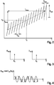
- Fig. 2 the frequency f of a transmission signal is shown over the time t, in the form of a sequence of (fast) frequency ramps (chirps), each of which has a stroke F fast and a time duration T almost .
- the individual frequency ramps follow one another with a time interval T r2r ("ramp-to-ramp").
- T r2r time interval
- the example shown is T almost equal to T r2r , so that the individual frequency ramps follow one another directly.
- Fig. 2 shows a general representation in which the center frequency of the individual frequency ramps changes in the course of the sequence.
- the center frequency of the fast ramps in turn describes a linear frequency ramp with the center frequency f 0 at time t 0 .
- the fast ramps of the sequence are identical, i.e. describe identical frequency profiles.
- Two or more different sequences of fast ramps are used in a measuring cycle, the fast ramps (chirps) each having the same frequency deviation F almost and the same ramp duration T almost and the same time interval T r2r between the ramps within the respective sequence.
- the at least two sequences within a measurement cycle can vary by different values of the amount and / or the sign of the frequency F, for example, almost the fast ramps, ramp different durations of the fast ramps, different Rampenwiederhol devis T r2r the fast ramps, different Center frequencies f 0 of the slow ramps, different number N slow of the fast ramps and / or different frequency sweeps F slow of the slow ramp.
- the frequency of the transmission signal is, for example, in the range of 76 GHz.
- the center frequency of the slow ramp can be 76 GHz.
- each fast ramp is subsequently assigned a partial signal with the duration T almost . It can be assumed that the signal transit time for a radar object in the detection range of the radar sensor system is short compared to the ramp duration T almost .
- a frequency spectrum of at least one partial signal is evaluated.
- the sub-signal of the baseband signal which corresponds to a fast ramp, is sampled, ie digitized, at a number N of almost equidistant times, and a frequency spectrum of the sub-signal is determined.
- the frequency spectrum is calculated, for example, by calculating a fast Fourier transform (FFT).
- FFT fast Fourier transform
- Fig. 3 schematically shows the amplitude A bb and the phase ⁇ bb of the signal obtained in polar coordinates plotted over the frequency bin k.
- a peak with the amplitude A bb (k o ) is obtained in the frequency bin k 0 , to which a corresponding phase ⁇ bb (k o ) is assigned.
- the frequency bin k o identifies the frequency position of the radar object in the relevant frequency spectrum of the partial signal.
- the frequency position of a peak assigned to a radar object is composed of a sum of two terms, of which the first term is proportional to the product of the distance D of the Radar object from the radar sensor and the ramp stroke F is almost and the second term is proportional to the product of the relative speed V of the radar object, the center frequency of the fast ramp and the ramp duration T is almost .
- This corresponds to the FMCW equation k O 2 / c D 0 . r F nearly + f 0 . r V 0 . r T nearly .
- the sequence of the fast ramps results in approximately the same frequency position of the peak, and in the following k 0 shall denote this mean frequency bin of the radar object over all fast ramps of the sequence.
- phase ⁇ bb (k o ) associated with the peak at the frequency position k 0 is particularly sensitive to changes in the distance of the radar object while passing through the sequence of fast ramps. A change in distance by half the wavelength of the radar signal already results in a phase shift by an entire period of the oscillation.
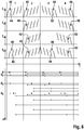
- Fig. 4 shows schematically with a solid line the temporal course of the real part of the spectrum corresponding to a harmonic oscillation A bb * cos ⁇ bb k O at the frequency position k 0 of the radar object in the frequency spectra during the course of the sequence of fast ramps.
- the harmonic oscillation shown in solid lines corresponds to a case without acceleration of the radar object.
- the wavelength is approximately 4 mm.
- the phase changes with a frequency of 12000 Hz.
- a peak corresponding to this frequency is expected in the frequency spectrum of the temporal course of the real part, the temporal course of the successive fast ramps corresponds; each ramp corresponds to a sample of the course over time. If the Nyquist-Shannon sampling theorem is violated by a sampling frequency of the phase changes that is too low, ie a ramp follow-up time T r2r , the frequency of the phase changes cannot be clearly determined.
- Fig. 4 schematically shows such a subsampling.
- the values of the real part at the middle times of the respective fast ramps are marked. It cannot be decided whether the true frequency of the phase changes is indicated by the curve drawn in solid lines or by the curve drawn in dashed lines. The frequency is therefore ambiguous.
- the frequency position of the harmonic oscillation corresponding to the phase change can be determined by subjecting the function, which indicates the phase ⁇ bb (r) measured for an object as a function of the ramp index r, to a Fourier transformation again.
- This frequency position can be indicated by its frequency bin I 0 and is approximately additively composed of a term proportional to the mean distance D and the ramp stroke F slow of the slow ramp and a term related to the mean relative speed V, the ramp duration T slow of the slow ramp and the center frequency f 0 is proportional to the slow ramp.
- I 0 2 / c D F slow + V T slow f O ,
- the determined frequency position thus results in a linear relationship between the relative speed and the distance of the radar object, which, however, is ambiguous with regard to the relative speed V and the distance D.
- This relationship represents a second piece of information about the relative speed and the distance of the radar object.
- F slow 0, the term “slow ramp” is used in the following; this has the slope 0 and gives second information only about the speed. With regard to the relative speed V, this is unambiguous except for integral multiples of the product of half the wavelength and the sampling frequency 1 / T r2r of the slow ramp.
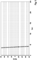
- Fig. 5 shows by way of example the information about the relative speed V and the distance D resulting from the evaluation of the measurement signal for a sequence of frequency ramps.
- the determination of the relative speed and distance of the radar object can be made unambiguous by taking further first information about relative speed and distance and / or further second information about relative speed and optionally distance into account.
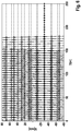
- Fig. 6 illustrates schematically a clear determination of relative speeds and distances of radar objects when using two different modulation patterns in each measurement cycle.
- these can be standing targets to which one's own motor vehicle is moving at a speed of 30 m / s.
- the linear relationships between V and D differ for the two modulation patterns.
- the first modulation pattern provides a family of parallel, falling lines, one line for each object.
- the second modulation pattern accordingly provides a family of rising straight lines.
- the second information about the speed V of the radar object determined from the two modulation patterns has different ambiguity ranges.
- Fig. 6 are the intersections of the straight lines as in Fig. 5 marked with circles.
- the signals obtained from the two modulation patterns are compared by looking for those values for the relative speed V and the distance D for which the straight line intersections provided by the two modulation patterns best match.
- the relative speed V -30 m / s is obtained for all objects.
- a cycle scheme is preferably used that in Fig. 7 is shown.
- the frequency f of the transmission signal is plotted against time t for two complete measuring cycles P.
- the frequency is modulated according to three different modulation patterns M 1 , M 2 and M 3 .
- Each modulation pattern is followed by a computing time interval of length T, within which the baseband signal obtained for the modulation pattern in question is evaluated.
- the results obtained for the last three modulation patterns are also compared within each computing time interval.
- this is symbolically represented for the computing time intervals in the second measuring cycle.
- This measuring cycle contains three sub-cycles Z 1 , Z 2 and Z 3 .
- sub-cycle Z 1 the result (the family of straight lines in the VD diagram) obtained for the modulation pattern M 1 in the current measurement cycle is compared with the results obtained for the modulation patterns M 2 and M 3 in the previous two Has received partial cycles (within the previous measuring cycle P). Through this comparison you get for each object has a unique pair of values for distance and relative speed that can be output at the end of this sub-cycle.
- sub-cycle Z 2 the result obtained for the modulation pattern M 2 in this sub-cycle is compared with the result for the immediately preceding modulation pattern M 1 and the preceding modulation pattern M 3 .
- the same procedure is followed for sub-cycle Z 3 .
- the different positions of the antenna elements 10-16 lead to the fact that the radar beams, which were emitted by one and the same antenna element, were reflected on the object and then received by the different antenna elements, cover different run lengths and therefore phase differences exhibit. that depend on the azimuth angle ⁇ of the object.
- the associated intermediate frequency signals Zf 1 - Zf 4 also have corresponding phase differences.
- the amplitudes (amounts) of the received signals also differ from antenna element to antenna element, likewise depending on the azimuth angle ⁇ .
- the dependence of the complex amplitudes, ie the absolute amounts and phases, of the received signals on the azimuth angle ⁇ can be stored in the control and evaluation unit 30 for each antenna element in the form of an antenna diagram.
- An angle estimator 38 compares the complex amplitudes obtained in the four receiving channels with the antenna diagrams for each located object (each peak in the frequency spectrum), so as to estimate the azimuth angle ⁇ of the object.
- the most likely value for the azimuth angle is assumed to be the value at which the measured It is best to correlate amplitudes with the values read in the antenna diagrams.
- the complex amplitudes in the four channels also depend on which of the four antenna elements 10, 12, 14, 16 is used as the transmission element.
- This control vector determines the phase relationships between the complex amplitudes of the signals received by the four antenna elements.
- the index ⁇ denotes the antenna element, and the sizes d r ⁇ indicate the positions of the antenna elements in the horizontal, based on any arbitrarily selected origin.
- the product vector has sixteen components, corresponding to sixteen positions of virtual antenna elements.
- the virtual antenna positions thus correspond to the sums that can be formed from the quantities d 1 - d 4 .
- the virtual array thus extends horizontally over a much larger span, that is, it has a larger aperture and thus leads to a higher angular resolution, since even small changes in the azimuth angle ⁇ lead to larger phase differences.
- the values d 1 - d 4 are chosen to be significantly larger than ⁇ / 2 in order to obtain the largest possible aperture, then due to the periodicity of the factor sin ( ⁇ ) Azimuth angles occur in individual cases in the components of the array vector, in which the antenna diagrams have similar complex amplitudes for all virtual antenna elements, so that the real azimuth angle of the object cannot be clearly determined.
- the virtual array is therefore preferably filled up by additional virtual elements.
- the switching network 22 is controlled in certain operating phases in such a way that two switches are closed simultaneously, that is to say two associated antenna elements 10, 12, 14, 16 are simultaneously fed with the same signal.
- the transmitted signals then overlap to form a signal whose wave pattern has approximately the shape as if it originated from a point in the middle between the relevant antenna elements.
- the antenna elements are fed together 10 and 12, one obtains in the control vector for the transmit array one additional component exp (2 ⁇ i ⁇ (d 2 / 2 ⁇ ) ⁇ sin ( ⁇ )) corresponding to an additional antenna element in the position of d 2/2.
- the four additional components, corresponding virtual elements results in the positions d 2/2, d 2/2 + d 2, d 2/2 + d 3 and d 2/2 + d. 4
- the antenna diagrams belonging to these virtual elements must also supply the complex amplitudes of the intermediate frequency signals Zf 1 -Zf 4 measured for the peak of the object. In this way, the additional elements help to avoid any ambiguity.
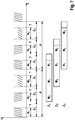
- the frequencies f 1 - f 4 of the signals transmitted by the antenna elements 10 - 16 are plotted as a function of the time t.
- a first period 1 only the antenna elements 10 and 16 are active and they send signals (frequencies f 1 and f 4 ) which consist of a rising slow frequency ramp 40, 42 with chirps 44, 46.
- the chirps 44 and 46 alternate with one another without to overlap each other in time. An overlay of the transmitted signals is avoided.
- the first chirp 46, which is transmitted with the antenna element 16 has the same frequency position and the same stroke as the first chirp 44, which is transmitted with the antenna element 10. So the two chirps are identical copies or repetitions. The same applies to each subsequent pair of chirps 44, 46.
- the sequences of chirps 44, 46 are generated in this example by the oscillator 24, which is alternately connected to the antenna elements 10 and 16 by the switching network 22.
- the frequency ramps 40, 42 are repeated.
- the switching network 22 now connects the oscillator to the two antenna elements 10 and 12 during the chirps 44 and to the two antenna elements 14 and 16 during the chirps 46, so that the transmit array in each case consists of a pair of adjacent antenna elements.
- slow frequency ramps 48, 50 falling with chirps 52, 54 are transmitted according to the same scheme. This completes a complete measurement cycle, which in this simplified example contains only two modulation patterns (a rising and a falling slow ramp).
- the positions d of the transmitting antenna elements (bold angles) and the positions of the respective virtual antenna elements (thinner angles) are symbolically shown for each period.
- the virtual positions for the chirps 44 match the real positions.
- the positions are offset by d 4 , since the antenna element 16 transmits which is offset by this distance from the antenna element 10.
- the transmit array for the chirps 44 has the same effect as an array with a single antenna element at the position d 2/2
- the transmit array for the chirps 46 has the same effect as an array with a single antenna element in the Position (d 3 + d 4 ) / 2.
- the virtual positions in periods 3 and 4 also result in the same way.
- An antenna diagram can be created for each of the virtual arrays, which indicates the amplitude and / or phase relationships of the signals received in the four evaluation channels as a function of the assumed angle of incidence ⁇ of the radar echo.
- the azimuth angle of the located object i.e. the actual angle of incidence ⁇
- the assumed angle of incidence ⁇ will correspond to the assumed angle of incidence ⁇ for which there is the best match between the amplitude and / or phase relationships actually measured in the evaluation channels and the corresponding values in the antenna diagram.
- a DML function Deterministic Maximum Likelihood
- the function value of the DML function varies between 0 (no correlation) and 1 (complete agreement).
- the four in this example Evaluation channels of measured amplitudes and / or phases (complex amplitudes) can be understood as a four-component vector. Accordingly, the values in the antenna diagrams form a four-component vector for each angle of incidence ⁇ .
- the DML function can then be calculated by normalizing these two vectors to 1 and then forming the dot product or the amount of the dot product or the square of the amount. The maximum of the DML function then provides the best estimate for the azimuth angle of the object.
- the angle estimator 38 forms the four-component amplitude vector for each of the chirps 44, 52 and for each peak found therein (that is to say for each localized object) and calculates the DML function using the antenna diagrams for the virtual array that occurs in periods 1 and 3 is used.
- the DML function is calculated on the basis of the antenna diagrams for the virtual array that is used in periods 2 and 4.
- the diagram (c) in Fig. 9 shows the DML function, which corresponds to a combination (a weighted sum) of the diagrams (a) and (b).
- the diagram (a) is weighted twice, because in the associated switching states, two antenna elements (10 and 12 or 14 and 16) are sent simultaneously.
- other types of weighting and other forms of combination e.g. median are also conceivable.
Landscapes
- Engineering & Computer Science (AREA)
- Radar, Positioning & Navigation (AREA)
- Remote Sensing (AREA)
- Physics & Mathematics (AREA)
- Computer Networks & Wireless Communication (AREA)
- General Physics & Mathematics (AREA)
- Electromagnetism (AREA)
- Computer Security & Cryptography (AREA)
- Radar Systems Or Details Thereof (AREA)
Claims (7)
- Détecteur radar FMCW à résolution angulaire constitué de plusieurs éléments d'antenne (10, 12, 14, 16), disposés dans différentes positions dans une direction dans laquelle le détecteur radar possède une résolution angulaire, qui forment au moins trois réseaux émetteurs et au moins un réseau récepteur, dans lequel un réseau émetteur peut être constitué d'un seul élément d'antenne ou d'une combinaison de plusieurs éléments d'antenne, et comprend un dispositif de commande et d'évaluation (30) qui est conçu pour un mode de fonctionnement dans lequel lesdits au moins trois réseaux émetteurs émettent des signaux périodiques dont la fréquence est modulée selon une suite de rampes de modulation (44, 46 ; 52, 54) et dans lequel des échos radar des signaux émis sont reçus respectivement par plusieurs éléments d'antenne dudit au moins un réseau récepteur et l'angle (θ) d'un objet localisé est déterminé sur la base de relations d'amplitude et/ou de phase entre les échos radar correspondant à différentes combinaisons de réseaux émetteurs et récepteurs, caractérisé en ce qu'un cycle de mesure (P) du détecteur radar comprend au moins deux périodes (1, 2, 3, 4) dans lesquelles une permutation est effectuée entre au moins deux combinaisons de réseaux émetteurs et récepteurs et un retour est effectué au cours d'autres périodes, et en ce que les combinaisons de réseaux émetteurs et récepteurs concernées sont différentes les unes des autres pour lesdites au moins deux périodes.
- Détecteur radar selon la revendication 1, dans lequel chaque période (1, 2, 3, 4) contient une série de rampes de modulation (44, 46 ; 52, 54) et est permutée après chaque rampe individuelle sur un réseau émetteur différent.
- Détecteur radar selon la revendication 1 ou 2, dans lequel la permutation entre deux réseaux émetteurs est effectuée en alternance au cours d'une même période (1, 2, 3, 4) .
- Détecteur radar selon l'une des revendications précédentes, dans lequel au moins l'un des réseaux émetteurs, qui est utilisé pour l'émission au cours d'au moins une période (1, 3), est constitué d'un élément antenne unique (10 ; 16), et au moins un autre réseau émetteur, qui est utilisé pour l'émission au cours d'au moins une période (2, 4), est constitué d'au moins deux éléments antenne (10, 12 ; 14, 16) qui sont alimentés simultanément avec des signaux de mêmes fréquences.
- Détecteur radar selon l'une des revendications précédentes, dans lequel chacun des éléments d'antenne (10, 12, 14, 16) peut fonctionner sélectivement en tant que partie d'un réseau récepteur et en tant que partie d'un réseau émetteur.
- Détecteur radar selon l'une des revendications précédentes, dans lequel les éléments d'antenne (10, 12, 14, 16) pouvant fonctionner en tant que partie d'un réseau émetteur présentent différents espacements de voisin à voisin.
- Détecteur radar selon l'une des revendications précédentes, dans lequel, pour déterminer la distance (D) d'un objet localisé, on évalue les différences de position de phase des échos radar reçus qui appartiennent à des motifs de modulation différents (M1, M2, M3) et dans lequel les résultats obtenus pour une pluralité de motifs de modulation successifs sont comparés les uns aux autres pour identifier les échos radar de plusieurs objets localisés simultanément, dans lequel au moins l'un desdits motifs de modulation provient d'un cycle de mesure précédent (P).
Applications Claiming Priority (2)
| Application Number | Priority Date | Filing Date | Title |
|---|---|---|---|
| DE102013212090.7A DE102013212090A1 (de) | 2013-06-25 | 2013-06-25 | Winkelauflösender FMCW-Radarsensor |
| PCT/EP2014/059851 WO2014206630A1 (fr) | 2013-06-25 | 2014-05-14 | Détecteur à radar fmcw à résolution angulaire |
Publications (2)
| Publication Number | Publication Date |
|---|---|
| EP3014297A1 EP3014297A1 (fr) | 2016-05-04 |
| EP3014297B1 true EP3014297B1 (fr) | 2020-01-15 |
Family
ID=50732169
Family Applications (1)
| Application Number | Title | Priority Date | Filing Date |
|---|---|---|---|
| EP14724426.3A Active EP3014297B1 (fr) | 2013-06-25 | 2014-05-14 | Détecteur à radar fmcw à résolution angulaire |
Country Status (6)
| Country | Link |
|---|---|
| US (1) | US10914818B2 (fr) |
| EP (1) | EP3014297B1 (fr) |
| JP (1) | JP6266103B2 (fr) |
| CN (1) | CN105339806B (fr) |
| DE (1) | DE102013212090A1 (fr) |
| WO (1) | WO2014206630A1 (fr) |
Cited By (2)
| Publication number | Priority date | Publication date | Assignee | Title |
|---|---|---|---|---|
| US20220003861A1 (en) * | 2018-11-19 | 2022-01-06 | Rheinmetall Waffe Munition Gmbh | Method for determining the position of an object, device for determining the position of an object, and system |
| DE102023207747A1 (de) | 2023-08-11 | 2025-02-13 | Robert Bosch Gesellschaft mit beschränkter Haftung | Hardwarebeschleunigereinrichtung, Radarvorrichtung und Verfahren zum Betreiben einer Radarvorrichtung |
Families Citing this family (96)
| Publication number | Priority date | Publication date | Assignee | Title |
|---|---|---|---|---|
| US10656257B2 (en) | 2013-04-29 | 2020-05-19 | Greina Technologies, Inc. | Personal radar |
| DE102013209708A1 (de) * | 2013-05-24 | 2014-11-27 | Robert Bosch Gmbh | Verfahren zum Betreiben eines MIMO Radars |
| JP6534808B2 (ja) * | 2014-11-28 | 2019-06-26 | 株式会社デンソーテン | レーダ装置、および、信号処理方法 |
| EP3324202B1 (fr) * | 2015-07-14 | 2026-04-22 | Mitsubishi Electric Corporation | Module de transmission, dispositif d'antenne réseau doté de celui-ci, et dispositif de transmission |
| DE102015226443A1 (de) | 2015-12-22 | 2017-06-22 | Robert Bosch Gmbh | Radarsensor, entsprechendes Betriebsverfahren und Fahrzeug |
| DE102016202936A1 (de) * | 2016-02-25 | 2017-08-31 | Robert Bosch Gmbh | Vorrichtung zum Ermitteln von Betriebsdaten für einen Radarsensor |
| DE102016203160A1 (de) * | 2016-02-29 | 2017-08-31 | Robert Bosch Gmbh | Radarsystem, umfassend eine Antennenanordnung zum Senden und Empfangen elektromagnetischer Strahlung |
| US10261179B2 (en) * | 2016-04-07 | 2019-04-16 | Uhnder, Inc. | Software defined automotive radar |
| US10627483B2 (en) | 2016-07-09 | 2020-04-21 | Texas Instruments Incorporated | Methods and apparatus for velocity detection in MIMO radar including velocity ambiguity resolution |
| FR3055049B1 (fr) * | 2016-08-11 | 2018-07-27 | Thales | Procede de detection radar fmcw a resolution multiple et radar mettant en oeuvre un tel procede |
| FR3055424B1 (fr) * | 2016-08-23 | 2019-01-25 | Thales | Methode de traitement d'un signal issu d'un lidar coherent et systeme lidar associe |
| DE102016218643A1 (de) * | 2016-09-28 | 2018-03-29 | Robert Bosch Gmbh | Verfahren zum Auswerten von Radarstrahlung und Radarvorrichtung |
| DE102016221947A1 (de) * | 2016-11-09 | 2018-05-09 | Robert Bosch Gmbh | Radarsensor für Kraftfahrzeuge |
| US10274594B2 (en) | 2016-12-06 | 2019-04-30 | GM Global Technology Operations LLC | Direct Doppler-free velocity measurement in linear frequency modulation radar |
| DE102016224900A1 (de) * | 2016-12-14 | 2018-06-14 | Robert Bosch Gmbh | MIMO-Radarsensor für Kraftfahrzeuge |
| EP3566072B1 (fr) * | 2017-01-04 | 2023-04-05 | Alps Alpine Co., Ltd. | Radar personnel |
| DE102017200273A1 (de) | 2017-01-10 | 2018-07-12 | Audi Ag | Radaranordnung für ein Kraftfahrzeug und Kraftfahrzeug |
| DE102017200317A1 (de) * | 2017-01-11 | 2018-07-12 | Robert Bosch Gmbh | Radarsensor und Verfahren zur Bestimmung einer Relativgeschwindigkeit eines Radarziels |
| DE102017200706A1 (de) * | 2017-01-18 | 2018-07-19 | Robert Bosch Gmbh | Mehrfach unterabgetastetes Chirp-Sequence-Radar |
| KR101945795B1 (ko) * | 2017-02-20 | 2019-02-11 | 국방과학연구소 | 확장 및 휴대 가능한 계측 레이더 시스템 |
| US10473755B1 (en) * | 2017-02-21 | 2019-11-12 | National Technology & Engineering Solutions Of Sandia, Llc | Waveform warping for general frequency-modulated radar waveforms |
| US10677918B2 (en) | 2017-02-28 | 2020-06-09 | Analog Devices, Inc. | Systems and methods for improved angular resolution in multiple-input multiple-output (MIMO) radar |
| WO2018158353A1 (fr) * | 2017-03-03 | 2018-09-07 | Iee International Electronics & Engineering S.A. | Procédé et système d'obtention d'une fonction d'ambiguïté d'angle doppler adaptative dans des radars mimo |
| DE102017105783B4 (de) * | 2017-03-17 | 2020-06-10 | S.M.S Smart Microwave Sensors Gmbh | Verfahren zum Bestimmen eines Abstandes und einer Geschwindigkeit eines Objektes |
| JP6945332B2 (ja) * | 2017-04-20 | 2021-10-06 | 株式会社デンソーテン | レーダ装置および物標検出方法 |
| DE102017209628A1 (de) * | 2017-06-08 | 2018-12-13 | Robert Bosch Gmbh | FMCW-Radarsensor für Kraftfahrzeuge |
| DE102017211432A1 (de) * | 2017-07-05 | 2019-01-10 | Robert Bosch Gmbh | System zum Detektieren eines bewegten Objekts |
| JP2019056670A (ja) * | 2017-09-22 | 2019-04-11 | ミツミ電機株式会社 | レーダー装置 |
| WO2019082269A1 (fr) * | 2017-10-24 | 2019-05-02 | 三菱電機株式会社 | Dispositif radar |
| DE102017011879A1 (de) * | 2017-12-21 | 2019-06-27 | Metirionic Gmbh | Funkfeld basierte Authentifizierung von Knoten innerhalb einer Funkverbindung |
| DE102018200394A1 (de) * | 2018-01-11 | 2019-07-11 | Robert Bosch Gmbh | Radarsystem mit in einem Radarsensorkopf integrierter Analyseeinheit |
| DE102018200751A1 (de) * | 2018-01-18 | 2019-07-18 | Robert Bosch Gmbh | Radarvorrichtung und Verfahren zum Betreiben einer Radarvorrichtung |
| DE102018200765A1 (de) * | 2018-01-18 | 2019-07-18 | Robert Bosch Gmbh | FMCW-Radarsensor |
| DE102018200752A1 (de) | 2018-01-18 | 2019-07-18 | Robert Bosch Gmbh | Verfahren und Vorrichtung zur Bewertung einer Winkelposition eines Objekts, und Fahrerassistenzsystem |
| DE102018201303A1 (de) | 2018-01-29 | 2019-08-01 | Robert Bosch Gmbh | Verfahren und Vorrichtung zum Betreiben von mehreren Sensoren eines Fahrzeugs |
| DE102018202290A1 (de) * | 2018-02-15 | 2019-08-22 | Robert Bosch Gmbh | Winkelschätzung und Mehrdeutigkeitsauflösung von Radarsensoren für Kraftfahrzeuge mit großem Antennenarray |
| DE102018202289A1 (de) * | 2018-02-15 | 2019-08-22 | Robert Bosch Gmbh | Winkelauflösender breitbandiger Radarsensor für Kraftfahrzeuge |
| GB201803239D0 (en) * | 2018-02-28 | 2018-04-11 | Secr Defence | A radio or sonic wave detector, transmitter, reciver and method thereof |
| DE102018203333A1 (de) * | 2018-03-06 | 2019-09-12 | Autocruise S.A.S | Verfahren zur eindeutigen Bestimmung der Geschwindigkeit eines Objekts an einem RADAR Messsystem |
| DE102018207718A1 (de) * | 2018-05-17 | 2019-11-21 | Robert Bosch Gmbh | Verfahren zur Phasenkalibrierung von Hochfrequenzbausteinen eines Radarsensors |
| DE102018208992A1 (de) * | 2018-06-07 | 2019-12-12 | Robert Bosch Gmbh | Radarsensorsystem |
| EP3581962A1 (fr) * | 2018-06-11 | 2019-12-18 | Hexagon Technology Center GmbH | Procédé de mesure de distance fmcw à deux faisceaux à compensation d'une erreur de mesure de distance dépendante de la vitesse |
| DE102018210155A1 (de) * | 2018-06-21 | 2019-12-24 | Robert Bosch Gmbh | Verfahren und Vorrichtung zur Auswertung von Radarsignalen |
| DE102018210083A1 (de) * | 2018-06-21 | 2019-12-24 | Robert Bosch Gmbh | Auswertevorrichtung und Verfahren zum Auswerten zumindest eines Radarsensors |
| US11585889B2 (en) * | 2018-07-25 | 2023-02-21 | Qualcomm Incorporated | Methods for radar coexistence |
| DE102018214586A1 (de) * | 2018-08-29 | 2020-03-05 | Robert Bosch Gmbh | Vorrichtung zum Empfangen von Licht zur Detektion eines Objekts |
| DE102018214966A1 (de) * | 2018-09-04 | 2020-03-05 | Robert Bosch Gmbh | Winkelauflösender Radarsensor |
| US11092686B2 (en) * | 2018-09-19 | 2021-08-17 | Steradian Semiconductors Private Limited | Method, apparatus and device for doppler compensation in a time switched MIMO radar system |
| JP7266207B2 (ja) * | 2018-09-28 | 2023-04-28 | パナソニックIpマネジメント株式会社 | レーダ装置、及び、レーダ方法 |
| DE102018124503A1 (de) * | 2018-10-04 | 2020-04-09 | HELLA GmbH & Co. KGaA | Radarsystem für ein Fahrzeug |
| DE102018124582A1 (de) | 2018-10-05 | 2020-04-09 | HELLA GmbH & Co. KGaA | Verfahren zur Erfassung bei einem Radarsystem |
| WO2020075689A1 (fr) * | 2018-10-12 | 2020-04-16 | 京セラ株式会社 | Dispositif électronique, procédé de commande de dispositif électronique et programme de commande de dispositif électronique |
| EP3874298A4 (fr) * | 2018-10-31 | 2022-10-26 | Cornell University | Système et procédé de télémétrie ultra-haute résolution à l'aide d'une identification par radiofréquence |
| WO2020090681A1 (fr) * | 2018-11-02 | 2020-05-07 | 株式会社村田製作所 | Dispositif d'antenne, corps mobile et procédé de détermination de cible |
| US11402483B2 (en) * | 2019-01-07 | 2022-08-02 | Niiva OpCo, LLC | Systems and methods to detect motion on sloped surfaces |
| KR102814886B1 (ko) * | 2019-03-11 | 2025-05-30 | 주식회사 에이치엘클레무브 | 레이더 장치, 레이더 장치용 안테나 장치 및 레이더 장치의 제어 방법 |
| US11681017B2 (en) | 2019-03-12 | 2023-06-20 | Uhnder, Inc. | Method and apparatus for mitigation of low frequency noise in radar systems |
| US11650317B2 (en) | 2019-06-28 | 2023-05-16 | Silc Technologies, Inc. | Use of frequency offsets in generation of LIDAR data |
| US11360210B2 (en) * | 2019-07-02 | 2022-06-14 | Intel Corporation | Multi-mode multi-input multi-output (MIMO) radar sensors |
| CH716417A1 (de) | 2019-07-19 | 2021-01-29 | Geopraevent Ag | Radargerät zum Erfassen von Objektbewegungen. |
| CN110346764B (zh) * | 2019-08-21 | 2022-03-29 | 上海无线电设备研究所 | 一种mimo雷达目标距离角度解耦方法 |
| DE102019214164A1 (de) * | 2019-09-17 | 2021-03-18 | Robert Bosch Gmbh | Radarsensor für Kraftfahrzeuge |
| CN112578341B (zh) * | 2019-09-30 | 2025-01-03 | 深圳引望智能技术有限公司 | 一种信号发送方法、信号处理方法及装置 |
| DE102019220216A1 (de) * | 2019-12-19 | 2021-06-24 | Robert Bosch Gmbh | Verfahren zum Abtasten zumindest eines Objekts und System zum Abtasten zumindest eines Objekts |
| US11953615B2 (en) | 2020-01-13 | 2024-04-09 | Uhnder Inc. | Method and system for antenna array calibration for cross-coupling and gain/phase variations in radar systems |
| CN112924961B (zh) * | 2020-01-13 | 2023-03-28 | 上海交通大学 | 基于微波感知的全场振动测量方法与系统 |
| DE112020005888T5 (de) * | 2020-02-21 | 2022-09-15 | Mitsubishi Electric Corporation | Radareinrichtung, beobachtungszielerfassungsverfahren und fahrzeuginterne einrichtung |
| DE102020202499A1 (de) * | 2020-02-27 | 2021-09-02 | Robert Bosch Gesellschaft mit beschränkter Haftung | MIMO-Radarsystem |
| DE102020202500A1 (de) * | 2020-02-27 | 2021-09-02 | Robert Bosch Gesellschaft mit beschränkter Haftung | MIMO-Radarsystem |
| DE102020202498A1 (de) * | 2020-02-27 | 2021-09-02 | Robert Bosch Gmbh | MIMO-Radarsystem |
| DE102020106276A1 (de) * | 2020-03-09 | 2021-09-09 | HELLA GmbH & Co. KGaA | Verfahren zum Betreiben eines Radarsystems für ein Fahrzeug |
| DE102020109502A1 (de) * | 2020-04-06 | 2021-10-07 | HELLA GmbH & Co. KGaA | Verfahren zur Bestimmung einer Winkelinformation |
| CN111526477B (zh) * | 2020-04-23 | 2021-08-10 | 上海交通大学 | 基于出发角的无线电定位方法及系统 |
| US11624826B2 (en) * | 2020-05-05 | 2023-04-11 | Silc Technologies, Inc. | Use of common chirp periods in generation of LIDAR data |
| DE112020007233T5 (de) * | 2020-05-25 | 2023-03-16 | Mitsubishi Electric Corporation | Radarvorrichtung |
| CN115917355B (zh) * | 2020-06-23 | 2024-06-14 | 华为技术有限公司 | 信号处理方法及装置、雷达装置、存储介质 |
| US20220018934A1 (en) * | 2020-07-14 | 2022-01-20 | Keysight Technologies, Inc. | Coordinated mini-radar target simulators for improved accuracy and improved ghost cancellation |
| DE102020119936A1 (de) * | 2020-07-29 | 2022-02-03 | Valeo Schalter Und Sensoren Gmbh | Radarsystem, Antennenarray für ein Radarsystem, Fahrzeug mit wenigstens einem Radarsystem und Verfahren zum Betreiben wenigstens eines Radarsystems |
| CN112118530B (zh) * | 2020-08-10 | 2022-08-16 | 苏州寻波科技有限公司 | 基于wifi信道状态信息的定位系统及方法 |
| US11709247B2 (en) * | 2020-09-22 | 2023-07-25 | Ay Dee Kay Llc | Fast chirp synthesis via segmented frequency shifting |
| DE102020212476A1 (de) | 2020-10-02 | 2022-04-07 | Robert Bosch Gesellschaft mit beschränkter Haftung | Radarvorrichtung und Verfahren zum Betreiben einer Radarvorrichtung |
| EP4012443A1 (fr) * | 2020-12-08 | 2022-06-15 | Veoneer Sweden AB | Système de radar de véhicule |
| WO2022171565A1 (fr) * | 2021-02-12 | 2022-08-18 | Symeo Gmbh | Système radar et procédé correspondant |
| US12541009B2 (en) | 2021-06-17 | 2026-02-03 | Silc Technologies, Inc. | Scanning multiple LIDAR system output signals |
| TWI771103B (zh) * | 2021-07-14 | 2022-07-11 | 立積電子股份有限公司 | 雷達裝置及其訊號接收方法 |
| US12411213B2 (en) | 2021-10-11 | 2025-09-09 | Silc Technologies, Inc. | Separation of light signals in a LIDAR system |
| WO2023100108A1 (fr) | 2021-12-02 | 2023-06-08 | Uhnder, Inc. | Système radar à traitement amélioré permettant un rapport de contraste accru, une séparation angulaire améliorée et l'élimination de cibles fantômes |
| DE102022200283A1 (de) | 2022-01-13 | 2023-07-13 | Robert Bosch Gesellschaft mit beschränkter Haftung | Radarsystem und Verfahren zum Betreiben eines Radarsystems |
| US12553995B2 (en) | 2022-02-14 | 2026-02-17 | Silc Technologies, Inc. | Data refinement in optical systems |
| JP7791032B2 (ja) * | 2022-04-07 | 2025-12-23 | 浜松ホトニクス株式会社 | 測距装置 |
| US12578443B2 (en) | 2022-04-23 | 2026-03-17 | Silc Technologies, Inc. | Data refinement in optical imaging systems |
| US12422618B2 (en) | 2022-10-13 | 2025-09-23 | Silc Technologies, Inc. | Buried taper with reflecting surface |
| US12578439B2 (en) | 2023-04-11 | 2026-03-17 | Silc Technologies, Inc. | Increasing resolution in imaging systems |
| US20250116755A1 (en) * | 2023-10-09 | 2025-04-10 | Nxp B.V. | Hybrid random time division multiplexing (rtdm) doppler division multiplexing (ddm) multiple-input multiple-output (mimo) radar system and method |
| DE102024124891A1 (de) * | 2024-08-30 | 2026-03-05 | Hensoldt Sensors Gmbh | Steuervorrichtung, antennenarray und verfahren zum ansteuern eines antennenarrays |
| JP7668606B1 (ja) * | 2025-01-27 | 2025-04-25 | 株式会社Athena | 構造物の監視点検システム、構造物の監視点検方法および構造物の監視点検用コンピュータプログラム |
Family Cites Families (18)
| Publication number | Priority date | Publication date | Assignee | Title |
|---|---|---|---|---|
| JP2989428B2 (ja) | 1993-06-17 | 1999-12-13 | 本田技研工業株式会社 | 時分割型fmレーダシステム |
| JP3393204B2 (ja) | 1999-10-06 | 2003-04-07 | 株式会社ホンダエレシス | マルチビームレーダ装置 |
| US6804312B1 (en) * | 2000-01-11 | 2004-10-12 | At&T Corp. | Methods and systems for spatial processing |
| US6750810B2 (en) * | 2001-12-18 | 2004-06-15 | Hitachi, Ltd. | Monopulse radar system |
| JP4067456B2 (ja) | 2003-06-09 | 2008-03-26 | 富士通テン株式会社 | レーダ装置及びその信号処理制御方法 |
| US20050225481A1 (en) * | 2004-04-12 | 2005-10-13 | Bonthron Andrew J | Method and apparatus for automotive radar sensor |
| JP2006003303A (ja) * | 2004-06-21 | 2006-01-05 | Fujitsu Ten Ltd | レーダ装置 |
| WO2007083479A1 (fr) * | 2006-01-23 | 2007-07-26 | Murata Manufacturing Co., Ltd. | Appareil radar |
| JP4905457B2 (ja) * | 2006-11-01 | 2012-03-28 | 株式会社村田製作所 | レーダの物標検知方法、およびこの物標検知方法を用いたレーダ装置 |
| JP4910651B2 (ja) | 2006-11-16 | 2012-04-04 | 株式会社デンソー | 通信統合レーダ装置、通信統合レーダシステム |
| DE102007043535A1 (de) * | 2007-09-12 | 2009-03-19 | Robert Bosch Gmbh | FMCW-Radarortungsvorrichtung und entsprechendes FMCW-Radarortungsverfahren |
| JP5470836B2 (ja) | 2008-12-19 | 2014-04-16 | 富士通株式会社 | 探知測距装置および探知測距装置の設計方法 |
| EP2629113B1 (fr) | 2009-04-06 | 2017-04-26 | Conti Temic microelectronic GmbH | Système radar doté d'agencements et procédé pour découpler des signaux d'émission et de réception ainsi que pour annuler des rayonnements parasites |
| JP2011064584A (ja) * | 2009-09-17 | 2011-03-31 | Denso Corp | アレーアンテナ装置及びレーダ装置 |
| DE102010030289A1 (de) * | 2010-06-21 | 2011-12-22 | Robert Bosch Gmbh | Radarsensor und Verfahren zum Betreiben eines Radarsensors |
| DE102010041755A1 (de) * | 2010-09-30 | 2012-04-05 | Siemens Aktiengesellschaft | Radarsystem |
| DE102012212888A1 (de) * | 2012-07-23 | 2014-01-23 | Robert Bosch Gmbh | Detektion von Radarobjekten mit einem Radarsensor eines Kraftfahrzeugs |
| US9620856B2 (en) * | 2012-11-19 | 2017-04-11 | Raytheon Company | Beam broadening with large spoil factors |
-
2013
- 2013-06-25 DE DE102013212090.7A patent/DE102013212090A1/de not_active Withdrawn
-
2014
- 2014-05-14 CN CN201480036459.5A patent/CN105339806B/zh not_active Expired - Fee Related
- 2014-05-14 US US14/900,688 patent/US10914818B2/en not_active Expired - Fee Related
- 2014-05-14 WO PCT/EP2014/059851 patent/WO2014206630A1/fr not_active Ceased
- 2014-05-14 JP JP2016520324A patent/JP6266103B2/ja not_active Expired - Fee Related
- 2014-05-14 EP EP14724426.3A patent/EP3014297B1/fr active Active
Non-Patent Citations (1)
| Title |
|---|
| None * |
Cited By (3)
| Publication number | Priority date | Publication date | Assignee | Title |
|---|---|---|---|---|
| US20220003861A1 (en) * | 2018-11-19 | 2022-01-06 | Rheinmetall Waffe Munition Gmbh | Method for determining the position of an object, device for determining the position of an object, and system |
| US11762083B2 (en) * | 2018-11-19 | 2023-09-19 | Rheinmetall Waffe Munition Gmbh | Method for determining the position of an object, device for determining the position of an object, and system |
| DE102023207747A1 (de) | 2023-08-11 | 2025-02-13 | Robert Bosch Gesellschaft mit beschränkter Haftung | Hardwarebeschleunigereinrichtung, Radarvorrichtung und Verfahren zum Betreiben einer Radarvorrichtung |
Also Published As
| Publication number | Publication date |
|---|---|
| US10914818B2 (en) | 2021-02-09 |
| CN105339806A (zh) | 2016-02-17 |
| DE102013212090A1 (de) | 2015-01-08 |
| CN105339806B (zh) | 2019-03-01 |
| JP2016525209A (ja) | 2016-08-22 |
| US20160131742A1 (en) | 2016-05-12 |
| EP3014297A1 (fr) | 2016-05-04 |
| JP6266103B2 (ja) | 2018-01-24 |
| WO2014206630A1 (fr) | 2014-12-31 |
Similar Documents
| Publication | Publication Date | Title |
|---|---|---|
| EP3014297B1 (fr) | Détecteur à radar fmcw à résolution angulaire | |
| EP2755045B1 (fr) | Procédé de mesure cyclique de distances et de vitesses d'objets à l'aide d'un détecteur radar à onde continue à fréquence modulée (FMCW) | |
| DE102018127947B3 (de) | Mimo fmcw radarsystem | |
| EP3004918B1 (fr) | Suppression d'interférences dans un radar fmcw | |
| DE102008014918B4 (de) | Verfahren zum Erfassen einer Interferenz in einem Radarsystem und Radar, das das gleiche verwendet | |
| EP2948789B1 (fr) | Radar fmcw à répartition en plages de distance | |
| DE112007003175B4 (de) | Elektronisch abtastendes Radarsystem | |
| EP3161513B1 (fr) | Procédé de mésure de radar avec des zones de vision différentes | |
| DE102013212079A1 (de) | Winkelauflösender Radarsensor | |
| EP3155444B1 (fr) | Procédé de localisation d'un objet avec un radar fmcw | |
| EP3161510B1 (fr) | Procédé de mesure par radar | |
| EP2659284B1 (fr) | Capteur radar pour véhicules | |
| EP2769236B1 (fr) | Capteur radar à résolution angulaire | |
| DE102012212888A1 (de) | Detektion von Radarobjekten mit einem Radarsensor eines Kraftfahrzeugs | |
| DE102008014787A1 (de) | Verfahren zum Erfassen einer Interferenz in einem Radarsystem und Radar, das das gleiche verwendet | |
| DE102014212284A1 (de) | MIMO-Radarmessverfahren | |
| DE102008054228A1 (de) | Fahrzeugseitige Richtungserkennungsvorrichtung zur genauen Erkennung von Zielkörperrichtungen ungeachtet der Fahrgeschwindigkeit | |
| WO2019158252A1 (fr) | Capteur radar à large bande à résolution angulaire pour véhicules automobiles | |
| DE102007035368A1 (de) | Radarvorrichtung | |
| CH721644B1 (de) | Verfahren zur Bestimmung der Position und des Verformungsgrades eines Überwachungsobjekts mit einem auf PMCW-MIMO basierenden Radarüberwachungssystem. | |
| DE102021213495A1 (de) | Radarmessverfahren | |
| DE102019219649A1 (de) | Kooperatives Radarsensorsystem mit winkelauflösenden Radarsensoren | |
| DE102023205898A1 (de) | Radarsensornetzwerk und Verfahren zur Bestimmung der Relativgeschwindig-keit eines Radarziels | |
| DE102023208722A1 (de) | Kohärentes Lidarsystem zur Umgebungserfassung mit binärer Leistungsmodulation und geringem Prozessierungsaufwand | |
| WO2024165224A1 (fr) | Procédé de détection d'objet et système de capteur radar fmcw à résolution angulaire |
Legal Events
| Date | Code | Title | Description |
|---|---|---|---|
| PUAI | Public reference made under article 153(3) epc to a published international application that has entered the european phase |
Free format text: ORIGINAL CODE: 0009012 |
|
| 17P | Request for examination filed |
Effective date: 20160125 |
|
| AK | Designated contracting states |
Kind code of ref document: A1 Designated state(s): AL AT BE BG CH CY CZ DE DK EE ES FI FR GB GR HR HU IE IS IT LI LT LU LV MC MK MT NL NO PL PT RO RS SE SI SK SM TR |
|
| AX | Request for extension of the european patent |
Extension state: BA ME |
|
| DAX | Request for extension of the european patent (deleted) | ||
| STAA | Information on the status of an ep patent application or granted ep patent |
Free format text: STATUS: EXAMINATION IS IN PROGRESS |
|
| 17Q | First examination report despatched |
Effective date: 20180606 |
|
| GRAP | Despatch of communication of intention to grant a patent |
Free format text: ORIGINAL CODE: EPIDOSNIGR1 |
|
| STAA | Information on the status of an ep patent application or granted ep patent |
Free format text: STATUS: GRANT OF PATENT IS INTENDED |
|
| INTG | Intention to grant announced |
Effective date: 20191021 |
|
| GRAS | Grant fee paid |
Free format text: ORIGINAL CODE: EPIDOSNIGR3 |
|
| GRAA | (expected) grant |
Free format text: ORIGINAL CODE: 0009210 |
|
| STAA | Information on the status of an ep patent application or granted ep patent |
Free format text: STATUS: THE PATENT HAS BEEN GRANTED |
|
| AK | Designated contracting states |
Kind code of ref document: B1 Designated state(s): AL AT BE BG CH CY CZ DE DK EE ES FI FR GB GR HR HU IE IS IT LI LT LU LV MC MK MT NL NO PL PT RO RS SE SI SK SM TR |
|
| REG | Reference to a national code |
Ref country code: CH Ref legal event code: EP Ref country code: GB Ref legal event code: FG4D Free format text: NOT ENGLISH |
|
| REG | Reference to a national code |
Ref country code: IE Ref legal event code: FG4D Free format text: LANGUAGE OF EP DOCUMENT: GERMAN |
|
| REG | Reference to a national code |
Ref country code: DE Ref legal event code: R096 Ref document number: 502014013480 Country of ref document: DE |
|
| REG | Reference to a national code |
Ref country code: AT Ref legal event code: REF Ref document number: 1225624 Country of ref document: AT Kind code of ref document: T Effective date: 20200215 |
|
| RAP2 | Party data changed (patent owner data changed or rights of a patent transferred) |
Owner name: ROBERT BOSCH GMBH |
|
| REG | Reference to a national code |
Ref country code: SE Ref legal event code: TRGR |
|
| REG | Reference to a national code |
Ref country code: NL Ref legal event code: MP Effective date: 20200115 |
|
| REG | Reference to a national code |
Ref country code: LT Ref legal event code: MG4D |
|
| PG25 | Lapsed in a contracting state [announced via postgrant information from national office to epo] |
Ref country code: NL Free format text: LAPSE BECAUSE OF FAILURE TO SUBMIT A TRANSLATION OF THE DESCRIPTION OR TO PAY THE FEE WITHIN THE PRESCRIBED TIME-LIMIT Effective date: 20200115 Ref country code: FI Free format text: LAPSE BECAUSE OF FAILURE TO SUBMIT A TRANSLATION OF THE DESCRIPTION OR TO PAY THE FEE WITHIN THE PRESCRIBED TIME-LIMIT Effective date: 20200115 Ref country code: NO Free format text: LAPSE BECAUSE OF FAILURE TO SUBMIT A TRANSLATION OF THE DESCRIPTION OR TO PAY THE FEE WITHIN THE PRESCRIBED TIME-LIMIT Effective date: 20200415 Ref country code: PT Free format text: LAPSE BECAUSE OF FAILURE TO SUBMIT A TRANSLATION OF THE DESCRIPTION OR TO PAY THE FEE WITHIN THE PRESCRIBED TIME-LIMIT Effective date: 20200607 Ref country code: RS Free format text: LAPSE BECAUSE OF FAILURE TO SUBMIT A TRANSLATION OF THE DESCRIPTION OR TO PAY THE FEE WITHIN THE PRESCRIBED TIME-LIMIT Effective date: 20200115 |
|
| PG25 | Lapsed in a contracting state [announced via postgrant information from national office to epo] |
Ref country code: LV Free format text: LAPSE BECAUSE OF FAILURE TO SUBMIT A TRANSLATION OF THE DESCRIPTION OR TO PAY THE FEE WITHIN THE PRESCRIBED TIME-LIMIT Effective date: 20200115 Ref country code: HR Free format text: LAPSE BECAUSE OF FAILURE TO SUBMIT A TRANSLATION OF THE DESCRIPTION OR TO PAY THE FEE WITHIN THE PRESCRIBED TIME-LIMIT Effective date: 20200115 Ref country code: BG Free format text: LAPSE BECAUSE OF FAILURE TO SUBMIT A TRANSLATION OF THE DESCRIPTION OR TO PAY THE FEE WITHIN THE PRESCRIBED TIME-LIMIT Effective date: 20200415 Ref country code: GR Free format text: LAPSE BECAUSE OF FAILURE TO SUBMIT A TRANSLATION OF THE DESCRIPTION OR TO PAY THE FEE WITHIN THE PRESCRIBED TIME-LIMIT Effective date: 20200416 Ref country code: IS Free format text: LAPSE BECAUSE OF FAILURE TO SUBMIT A TRANSLATION OF THE DESCRIPTION OR TO PAY THE FEE WITHIN THE PRESCRIBED TIME-LIMIT Effective date: 20200515 |
|
| REG | Reference to a national code |
Ref country code: DE Ref legal event code: R097 Ref document number: 502014013480 Country of ref document: DE |
|
| PG25 | Lapsed in a contracting state [announced via postgrant information from national office to epo] |
Ref country code: EE Free format text: LAPSE BECAUSE OF FAILURE TO SUBMIT A TRANSLATION OF THE DESCRIPTION OR TO PAY THE FEE WITHIN THE PRESCRIBED TIME-LIMIT Effective date: 20200115 Ref country code: SM Free format text: LAPSE BECAUSE OF FAILURE TO SUBMIT A TRANSLATION OF THE DESCRIPTION OR TO PAY THE FEE WITHIN THE PRESCRIBED TIME-LIMIT Effective date: 20200115 Ref country code: CZ Free format text: LAPSE BECAUSE OF FAILURE TO SUBMIT A TRANSLATION OF THE DESCRIPTION OR TO PAY THE FEE WITHIN THE PRESCRIBED TIME-LIMIT Effective date: 20200115 Ref country code: LT Free format text: LAPSE BECAUSE OF FAILURE TO SUBMIT A TRANSLATION OF THE DESCRIPTION OR TO PAY THE FEE WITHIN THE PRESCRIBED TIME-LIMIT Effective date: 20200115 Ref country code: RO Free format text: LAPSE BECAUSE OF FAILURE TO SUBMIT A TRANSLATION OF THE DESCRIPTION OR TO PAY THE FEE WITHIN THE PRESCRIBED TIME-LIMIT Effective date: 20200115 Ref country code: ES Free format text: LAPSE BECAUSE OF FAILURE TO SUBMIT A TRANSLATION OF THE DESCRIPTION OR TO PAY THE FEE WITHIN THE PRESCRIBED TIME-LIMIT Effective date: 20200115 Ref country code: DK Free format text: LAPSE BECAUSE OF FAILURE TO SUBMIT A TRANSLATION OF THE DESCRIPTION OR TO PAY THE FEE WITHIN THE PRESCRIBED TIME-LIMIT Effective date: 20200115 Ref country code: SK Free format text: LAPSE BECAUSE OF FAILURE TO SUBMIT A TRANSLATION OF THE DESCRIPTION OR TO PAY THE FEE WITHIN THE PRESCRIBED TIME-LIMIT Effective date: 20200115 |
|
| PLBE | No opposition filed within time limit |
Free format text: ORIGINAL CODE: 0009261 |
|
| STAA | Information on the status of an ep patent application or granted ep patent |
Free format text: STATUS: NO OPPOSITION FILED WITHIN TIME LIMIT |
|
| 26N | No opposition filed |
Effective date: 20201016 |
|
| PG25 | Lapsed in a contracting state [announced via postgrant information from national office to epo] |
Ref country code: MC Free format text: LAPSE BECAUSE OF FAILURE TO SUBMIT A TRANSLATION OF THE DESCRIPTION OR TO PAY THE FEE WITHIN THE PRESCRIBED TIME-LIMIT Effective date: 20200115 Ref country code: CH Free format text: LAPSE BECAUSE OF NON-PAYMENT OF DUE FEES Effective date: 20200531 Ref country code: LI Free format text: LAPSE BECAUSE OF NON-PAYMENT OF DUE FEES Effective date: 20200531 Ref country code: IT Free format text: LAPSE BECAUSE OF FAILURE TO SUBMIT A TRANSLATION OF THE DESCRIPTION OR TO PAY THE FEE WITHIN THE PRESCRIBED TIME-LIMIT Effective date: 20200115 |
|
| PG25 | Lapsed in a contracting state [announced via postgrant information from national office to epo] |
Ref country code: SI Free format text: LAPSE BECAUSE OF FAILURE TO SUBMIT A TRANSLATION OF THE DESCRIPTION OR TO PAY THE FEE WITHIN THE PRESCRIBED TIME-LIMIT Effective date: 20200115 Ref country code: PL Free format text: LAPSE BECAUSE OF FAILURE TO SUBMIT A TRANSLATION OF THE DESCRIPTION OR TO PAY THE FEE WITHIN THE PRESCRIBED TIME-LIMIT Effective date: 20200115 |
|
| REG | Reference to a national code |
Ref country code: BE Ref legal event code: MM Effective date: 20200531 |
|
| PG25 | Lapsed in a contracting state [announced via postgrant information from national office to epo] |
Ref country code: LU Free format text: LAPSE BECAUSE OF NON-PAYMENT OF DUE FEES Effective date: 20200514 |
|
| PG25 | Lapsed in a contracting state [announced via postgrant information from national office to epo] |
Ref country code: IE Free format text: LAPSE BECAUSE OF NON-PAYMENT OF DUE FEES Effective date: 20200514 |
|
| PG25 | Lapsed in a contracting state [announced via postgrant information from national office to epo] |
Ref country code: BE Free format text: LAPSE BECAUSE OF NON-PAYMENT OF DUE FEES Effective date: 20200531 |
|
| REG | Reference to a national code |
Ref country code: AT Ref legal event code: MM01 Ref document number: 1225624 Country of ref document: AT Kind code of ref document: T Effective date: 20200514 |
|
| PGFP | Annual fee paid to national office [announced via postgrant information from national office to epo] |
Ref country code: FR Payment date: 20210525 Year of fee payment: 8 |
|
| PG25 | Lapsed in a contracting state [announced via postgrant information from national office to epo] |
Ref country code: AT Free format text: LAPSE BECAUSE OF NON-PAYMENT OF DUE FEES Effective date: 20200514 |
|
| PGFP | Annual fee paid to national office [announced via postgrant information from national office to epo] |
Ref country code: SE Payment date: 20210521 Year of fee payment: 8 Ref country code: GB Payment date: 20210525 Year of fee payment: 8 |
|
| PG25 | Lapsed in a contracting state [announced via postgrant information from national office to epo] |
Ref country code: TR Free format text: LAPSE BECAUSE OF FAILURE TO SUBMIT A TRANSLATION OF THE DESCRIPTION OR TO PAY THE FEE WITHIN THE PRESCRIBED TIME-LIMIT Effective date: 20200115 Ref country code: MT Free format text: LAPSE BECAUSE OF FAILURE TO SUBMIT A TRANSLATION OF THE DESCRIPTION OR TO PAY THE FEE WITHIN THE PRESCRIBED TIME-LIMIT Effective date: 20200115 Ref country code: CY Free format text: LAPSE BECAUSE OF FAILURE TO SUBMIT A TRANSLATION OF THE DESCRIPTION OR TO PAY THE FEE WITHIN THE PRESCRIBED TIME-LIMIT Effective date: 20200115 |
|
| PG25 | Lapsed in a contracting state [announced via postgrant information from national office to epo] |
Ref country code: MK Free format text: LAPSE BECAUSE OF FAILURE TO SUBMIT A TRANSLATION OF THE DESCRIPTION OR TO PAY THE FEE WITHIN THE PRESCRIBED TIME-LIMIT Effective date: 20200115 Ref country code: AL Free format text: LAPSE BECAUSE OF FAILURE TO SUBMIT A TRANSLATION OF THE DESCRIPTION OR TO PAY THE FEE WITHIN THE PRESCRIBED TIME-LIMIT Effective date: 20200115 |
|
| REG | Reference to a national code |
Ref country code: SE Ref legal event code: EUG |
|
| GBPC | Gb: european patent ceased through non-payment of renewal fee |
Effective date: 20220514 |
|
| PG25 | Lapsed in a contracting state [announced via postgrant information from national office to epo] |
Ref country code: SE Free format text: LAPSE BECAUSE OF NON-PAYMENT OF DUE FEES Effective date: 20220515 |
|
| PG25 | Lapsed in a contracting state [announced via postgrant information from national office to epo] |
Ref country code: FR Free format text: LAPSE BECAUSE OF NON-PAYMENT OF DUE FEES Effective date: 20220531 |
|
| PG25 | Lapsed in a contracting state [announced via postgrant information from national office to epo] |
Ref country code: GB Free format text: LAPSE BECAUSE OF NON-PAYMENT OF DUE FEES Effective date: 20220514 |
|
| PGFP | Annual fee paid to national office [announced via postgrant information from national office to epo] |
Ref country code: DE Payment date: 20250716 Year of fee payment: 12 |