EP3012923B1 - Pince de pression - Google Patents
Pince de pression Download PDFInfo
- Publication number
- EP3012923B1 EP3012923B1 EP14189548.2A EP14189548A EP3012923B1 EP 3012923 B1 EP3012923 B1 EP 3012923B1 EP 14189548 A EP14189548 A EP 14189548A EP 3012923 B1 EP3012923 B1 EP 3012923B1
- Authority
- EP
- European Patent Office
- Prior art keywords
- spring
- spring element
- crimping pliers
- dies
- pliers
- Prior art date
- Legal status (The legal status is an assumption and is not a legal conclusion. Google has not performed a legal analysis and makes no representation as to the accuracy of the status listed.)
- Active
Links
- 230000007246 mechanism Effects 0.000 claims description 51
- 238000002788 crimping Methods 0.000 claims description 44
- 230000033001 locomotion Effects 0.000 claims description 40
- 238000005452 bending Methods 0.000 claims description 35
- 238000013461 design Methods 0.000 claims description 17
- 238000005096 rolling process Methods 0.000 claims description 7
- 230000008859 change Effects 0.000 claims description 4
- 230000007423 decrease Effects 0.000 claims 1
- 238000003825 pressing Methods 0.000 description 141
- 210000003127 knee Anatomy 0.000 description 21
- 238000006073 displacement reaction Methods 0.000 description 20
- 230000036961 partial effect Effects 0.000 description 20
- 230000005489 elastic deformation Effects 0.000 description 9
- 230000001965 increasing effect Effects 0.000 description 8
- 239000004033 plastic Substances 0.000 description 8
- 229920003023 plastic Polymers 0.000 description 8
- 230000000670 limiting effect Effects 0.000 description 7
- 210000000629 knee joint Anatomy 0.000 description 6
- 230000015572 biosynthetic process Effects 0.000 description 5
- 210000002414 leg Anatomy 0.000 description 5
- 238000010276 construction Methods 0.000 description 4
- 239000000463 material Substances 0.000 description 4
- 230000009467 reduction Effects 0.000 description 4
- 230000002829 reductive effect Effects 0.000 description 4
- 230000000903 blocking effect Effects 0.000 description 3
- 230000009850 completed effect Effects 0.000 description 3
- 238000004519 manufacturing process Methods 0.000 description 3
- 238000000034 method Methods 0.000 description 3
- 230000008569 process Effects 0.000 description 3
- 230000009471 action Effects 0.000 description 2
- 230000006835 compression Effects 0.000 description 2
- 238000007906 compression Methods 0.000 description 2
- 239000004020 conductor Substances 0.000 description 2
- 230000008878 coupling Effects 0.000 description 2
- 238000010168 coupling process Methods 0.000 description 2
- 238000005859 coupling reaction Methods 0.000 description 2
- 230000001186 cumulative effect Effects 0.000 description 2
- 238000005553 drilling Methods 0.000 description 2
- 230000002349 favourable effect Effects 0.000 description 2
- 239000000835 fiber Substances 0.000 description 2
- 230000001976 improved effect Effects 0.000 description 2
- 230000010354 integration Effects 0.000 description 2
- 230000007935 neutral effect Effects 0.000 description 2
- 238000007493 shaping process Methods 0.000 description 2
- 239000007787 solid Substances 0.000 description 2
- 238000012546 transfer Methods 0.000 description 2
- 206010013710 Drug interaction Diseases 0.000 description 1
- 238000000418 atomic force spectrum Methods 0.000 description 1
- 230000006378 damage Effects 0.000 description 1
- 230000001419 dependent effect Effects 0.000 description 1
- 238000009826 distribution Methods 0.000 description 1
- 230000000694 effects Effects 0.000 description 1
- 210000003746 feather Anatomy 0.000 description 1
- 230000009975 flexible effect Effects 0.000 description 1
- 238000011068 loading method Methods 0.000 description 1
- 230000001603 reducing effect Effects 0.000 description 1
- 238000003860 storage Methods 0.000 description 1
- 230000008093 supporting effect Effects 0.000 description 1
- 238000012360 testing method Methods 0.000 description 1
- 230000007704 transition Effects 0.000 description 1
- 238000013519 translation Methods 0.000 description 1
Images


Classifications
-
- H—ELECTRICITY
- H01—ELECTRIC ELEMENTS
- H01R—ELECTRICALLY-CONDUCTIVE CONNECTIONS; STRUCTURAL ASSOCIATIONS OF A PLURALITY OF MUTUALLY-INSULATED ELECTRICAL CONNECTING ELEMENTS; COUPLING DEVICES; CURRENT COLLECTORS
- H01R43/00—Apparatus or processes specially adapted for manufacturing, assembling, maintaining, or repairing of line connectors or current collectors or for joining electric conductors
- H01R43/04—Apparatus or processes specially adapted for manufacturing, assembling, maintaining, or repairing of line connectors or current collectors or for joining electric conductors for forming connections by deformation, e.g. crimping tool
- H01R43/042—Hand tools for crimping
-
- B—PERFORMING OPERATIONS; TRANSPORTING
- B25—HAND TOOLS; PORTABLE POWER-DRIVEN TOOLS; MANIPULATORS
- B25B—TOOLS OR BENCH DEVICES NOT OTHERWISE PROVIDED FOR, FOR FASTENING, CONNECTING, DISENGAGING OR HOLDING
- B25B27/00—Hand tools, specially adapted for fitting together or separating parts or objects whether or not involving some deformation, not otherwise provided for
- B25B27/02—Hand tools, specially adapted for fitting together or separating parts or objects whether or not involving some deformation, not otherwise provided for for connecting objects by press fit or detaching same
- B25B27/10—Hand tools, specially adapted for fitting together or separating parts or objects whether or not involving some deformation, not otherwise provided for for connecting objects by press fit or detaching same inserting fittings into hoses
-
- B—PERFORMING OPERATIONS; TRANSPORTING
- B21—MECHANICAL METAL-WORKING WITHOUT ESSENTIALLY REMOVING MATERIAL; PUNCHING METAL
- B21J—FORGING; HAMMERING; PRESSING METAL; RIVETING; FORGE FURNACES
- B21J7/00—Hammers; Forging machines with hammers or die jaws acting by impact
- B21J7/02—Special design or construction
- B21J7/14—Forging machines working with several hammers
- B21J7/16—Forging machines working with several hammers in rotary arrangements
-
- H—ELECTRICITY
- H01—ELECTRIC ELEMENTS
- H01R—ELECTRICALLY-CONDUCTIVE CONNECTIONS; STRUCTURAL ASSOCIATIONS OF A PLURALITY OF MUTUALLY-INSULATED ELECTRICAL CONNECTING ELEMENTS; COUPLING DEVICES; CURRENT COLLECTORS
- H01R43/00—Apparatus or processes specially adapted for manufacturing, assembling, maintaining, or repairing of line connectors or current collectors or for joining electric conductors
- H01R43/04—Apparatus or processes specially adapted for manufacturing, assembling, maintaining, or repairing of line connectors or current collectors or for joining electric conductors for forming connections by deformation, e.g. crimping tool
- H01R43/042—Hand tools for crimping
- H01R43/0424—Hand tools for crimping with more than two radially actuated mandrels
-
- H—ELECTRICITY
- H01—ELECTRIC ELEMENTS
- H01R—ELECTRICALLY-CONDUCTIVE CONNECTIONS; STRUCTURAL ASSOCIATIONS OF A PLURALITY OF MUTUALLY-INSULATED ELECTRICAL CONNECTING ELEMENTS; COUPLING DEVICES; CURRENT COLLECTORS
- H01R43/00—Apparatus or processes specially adapted for manufacturing, assembling, maintaining, or repairing of line connectors or current collectors or for joining electric conductors
- H01R43/04—Apparatus or processes specially adapted for manufacturing, assembling, maintaining, or repairing of line connectors or current collectors or for joining electric conductors for forming connections by deformation, e.g. crimping tool
- H01R43/042—Hand tools for crimping
- H01R43/0425—Hand tools for crimping with mandrels actuated in axial direction to the wire
Definitions
- the invention relates to a pressing tongs for pressing a workpiece.
- This may be any pressing tongs, for example a pressing tongs for pressing pipe or pipe connections or a pressing tongs (which is also referred to as crimping tool) for pressing electrical line connections or plugs, sleeves or jacks with any electrical conductors.
- the crimping pliers may in principle have any of the various known constructive embodiments and drive mechanisms, wherein crimping with two or more dies or spikes (hereinafter collectively referred to as "dies”) may take place during the pressing process. According to the invention, it is a hand-operated pressing tongs.
- a pressing tongs can be used not only for pressing workpieces with a single geometry, a material rigidity and / or cross-sectional area (in the following simplified "" cross-sectional area), but also multifunctional for different workpieces with different cross-sectional areas
- Design of the components of the pressing tongs the pressing tongs designed for pressing a workpiece having a predetermined cross-sectional area the use of the crimping tool for a workpiece with a smaller cross-sectional area has the consequence that in this application, the required maximum pressing forces are not achieved while using the crimping tool for workpieces with a larger cross-sectional area after a partial stroke of the lever maximum pressing forces are generated so that the complete closure of the hand lever would lead to excessive pressing forces or the complete closure of the hand lever by manual operating forces is not possible.
- Remedy could only be provided in the past by equipping the pressing tongs with replaceable heads or interchangeable dies for the different cross-sectional areas of the workpieces.
- a pressing tool with a drive mechanism which has a mechanical pressing force limiting device.
- the mechanical pressing force limiting device limits the pressing force brought about by the pressing tool, irrespective of the size of a pressing stroke, to a predetermined set pressing force.
- the driving mechanism of the pressing tool can be designed so that when pressing a workpiece having a small cross sectional area, the required pressing force is brought about. If workpieces with larger cross-sectional areas are then used in such a pressing tool, excessive pressing forces or excessive actuating forces are avoided by triggering the mechanical pressing force limiting device.
- the mechanical pressing force limiting device drastically increases the design effort.
- DE 31 09 289 C2 also proposes resiliently supporting a pressure lever, here for a pressing tongs with scissor-type pressing jaws.
- the elastic support of the pressure lever is ensured by the lever in the region of the articulation point for the pressure lever has a taper in the form of a slot which leads to a branch of the fixed hand lever with a reduction in the material cross section of the fixed hand lever in the branch. This reduction of the material cross-section leads to an elastic deformation of the fixed hand lever in the acting pressing forces.
- the non-prepublished European patent application EP 14 154 206.8 relates to a pressing tongs in which the drive mechanism is formed with a toggle mechanism.
- the elasticity of the drive mechanism is not provided in the region of the bearing of the pressure lever, but rather in the pressure lever itself.
- the pressure lever is curved or cranked and flexible formed.
- DE 10 2013 100 801 A1 discloses the resilient support of a pressure lever on a spring arm formed by the fixed hand lever.
- US 341,303 S1 discloses a crimping tool for crimping tube connectors in which a toggle lever drive is used in formation with a roller and a guide member on which the roller rolls over the working stroke.
- the invention has for its object to propose an alternative and / or improved embodiment of a pressing tongs, which can be used for pressing workpieces with different cross-sectional areas.
- the invention has for its object to equip the crimping pliers with an alternative or improved force-displacement compensating element.
- the pressing tool according to the invention has two drive elements, in which it may be in the formation of pressing tongs as a manually operated pressing tongs to handle or hereby coupled components.
- the pressing tongs invention also has a pliers head. In the region of the pliers head actuating elements are arranged, which actuate the dies, between which the workpiece is pressed. These actuators can be fixed (but quite replaceable) coupled with the dies or directly interact with them (see, the documents EP 0 732 779 B1 .
- a spring element is provided in the pressing tongs.
- the spring element is arranged in the power flow between the drive elements and the dies and forms a force-displacement compensation element.
- a force-displacement compensating element is understood in particular to be a spring element which can be applied to the drive forces that can be applied to the drive elements (ie the maximum force of a power-operated drive or the maximum manual force) during a blocking of the closing movement of the dies (in particular with a Workpiece with too large a cross-section or as rigid a test specimen) allows a closing movement of the drive elements of at least 10% (for example, at least 20%, 30%, 50% or even 70% or 100%) of the entire working stroke of the drive elements.
- the area of application of the pressing tongs for pressing workpieces having different cross-sectional areas can be expanded.
- the spring element, which forms the force-displacement compensating element is formed in the region of the pliers head.
- the force-displacement compensating element may for example be integrated into a kind of housing of the pliers head, where this is only partially or not visible from the outside.
- the spring element which forms the force-displacement compensating element may be at least partially disposed between cover plates of the pliers head.
- a drive mechanism of any configuration is provided, which is interposed between the drive elements and the actuating elements.
- this drive mechanism can be designed as a toggle mechanism.
- the spring element which interposed the force-displacement compensating element in the power flow between the drive mechanism and the actuators.
- the spring element is arranged in the power flow after the drive mechanism, in which case the spring element is not part of the toggle mechanism for the design of the drive mechanism as a toggle mechanism.
- the integrated into the pliers head and the force-displacement compensating element forming spring element can be arbitrarily coupled to the other components of the crimping pliers, for example, integrally connected to another component or be attached in several pieces to this, be hinged to this in the region of a Federfußfewers or im Be guided area of a spring base or in any area of the spring element.
- a spring base of the spring element is attached to one of the actuating elements, this also being understood to mean a one-piece design of the spring element with this actuating element.
- the spring base of the spring element may be fastened to an actuating element designed as a pivot ring.
- the spring element may be formed for example as a tension or compression spring.
- the spring element is designed as a bending beam.
- the bending beam may have any geometry, for example, be formed straight or curved.
- the spring element formed as a bending beam is designed in plate construction. This allows a particularly simple production of the spring element, wherein depending on the design of the individual plates of the spring element targeted and with high accuracy, the elastic behavior of the spring element can be specified. It is even possible that pressing tongs are provided with different characteristics of the force-displacement compensation element by a different number of otherwise identical plates is used for the different spring elements. Under some circumstances, a plate construction may also be advantageous if the spring element is formed integrally with another component of the pressing tongs, in particular an actuating element or the swivel ring, so that both the spring element and the other component can be manufactured by means of the same plate and the production method used therefor ,
- the spring element (at least partially) extends in the circumferential direction about a Gesenkachse.
- the spring element with a circumferential direction of, for example, more than 90 °, more than 180 ° or even more than 270 ° extend around the Gesenkachse. It is possible that the spring element extends with a plurality of rectilinear, mutually inclined portions in the circumferential direction. But is also possible any curved course of the spring element in the circumferential direction.
- the spring element is designed as circular arc spring or coil spring.
- a circular-arc spring or coil spring results in a particularly favorable characteristic of the spring element, under certain circumstances, large spring travel are possible.
- an elasticity is brought about, which acts both in the circumferential direction about the Gesenkachse and in radial direction to the die axis, which may for example be advantageous for the integration of the spring element in the power flow between the drive elements, the drive mechanism and the actuators or dies.
- the course of the flexural rigidity over the longitudinal axis of the bending beam can be arbitrary.
- the bending beam has a bending stiffness varying in the direction of its (straight or curved longitudinal axis).
- the area moment of inertia of the bending beam increases from the spring base point, which is acted on by the drive mechanism, to a circumferential cross-section of the bending beam opposite that spring base, which increase can be continuous or in steps.
- the area moment of inertia of the bending beam is symmetrical to an axis of symmetry.
- the axis of symmetry runs approximately or exactly through the spring base on which the action by the drive mechanism takes place, and the cross section of the bending beam, which is opposite to this spring base in the circumferential direction.
- the die axis is preferably located on the said axis of symmetry.
- the dies can be fastened directly to an actuating element.
- an actuator on guides for dies The other actuator has actuating surfaces for the dies.
- relative movement of the actuators results in movement of the dies relative to the guides caused by the contact of the actuation surfaces with the dies.
- the actuating elements are pivoted relative to each other about the Gesenkachse, in which case, for example, an actuating element is designed as a pivot ring.
- the dies can be mounted pivotably relative to the guides, in particular by means of bearing bolts, which are held on the pliers head and store the dies with pliers head fixed bearing axis.
- the relative pivoting of the actuators has a pivoting of the dies relative to the guides result. This pivoting of the dies is caused by the contact of the actuating surfaces of the one actuating element with the dies.
- the end regions of the knee levers facing away from a knee joint of the knee lever mechanism can be mounted on a fixed storage location, for example on a drive element such as a hand lever and / or an actuating element such as a swivel ring.
- a drive element such as a hand lever and / or an actuating element such as a swivel ring.
- the effective lengths of the toggle lever and the course of the toggle lever over the working stroke of the toggle mechanism are structurally predetermined.
- the toggle mechanism is formed with a roller and a guide part.
- the working roller rolls off the roller on the guide part, which may be caused by the closure of the die with the pressing of the workpiece and on the other hand by an elastic deformation of the force-displacement compensating element in the invention, this rolling movement between roller and guide part Shape of the spring element.
- the shape of the cam track of the guide member and the choice of the component and the location at which the roller and the guide member are arranged a further influence on the characteristics of the drive mechanism can take place.
- guide member and roller can be arranged on any component or on any drive element
- the invention also proposes an embodiment in which the guide member is fixed to the drive element, to which an actuating element is attached.
- the drive element to which the guide part is fastened is a hand lever rigidly connected to an actuating element.
- the role of the other Drive element (in particular on a pivotally hinged to an actuating element hand lever) rotatably mounted.
- This configuration has the consequence that by means of the rolling of the roller on the guide part, a knee angle of the toggle mechanism can be changed.
- a knee angle can be predetermined in each case specifically via the working stroke, which meets the requirements.
- the knee angle always remains within an angular range, for example from 130 ° to 180 °, in particular 145 ° to 180 °, due to the rolling movement of the roller relative to the curved path of the guide part.
- the force ratios of the pressing tongs for the pressing of the workpiece are influenced exclusively by a single spring element, which then forms the force-displacement compensation element.
- a further spring element is provided, which provides a contact force of the roller to the curved path of the guide member, which also includes that a contact force of the roller to the curved path through the further spring element in addition to other the contact pressure supplementary funds.
- the invention proposes for a further embodiment, that the pressing tongs is formed with a Zwangsgesperre.
- a locking mechanism is understood, which on the one hand ensures a once during the working stroke of the pressing tongs partial pressing against an opening movement and on the other hand allows the opening movement of the pressing tongs only when the working stroke of the pressing tongs is completely traversed.
- the invention proposes that the Zwangsgesperre is formed with a Sperrveriereungshebel.
- the ratchet lever is rotatably supported about the axis of rotation of the roller. Off the axis of rotation of the pawl lever this forms two lever parts. An outer end region of a lever part forms the locking teeth of the Zwangsgesperres.
- the outer end portion of the other lever member is connected via a slot with the drive element to which the guide member is attached. About this slot, which may have any contour, despite the coupling of the axis of rotation of the pawl lever on the roller and the guide member with the drive element allows an articulation of the slot equipped end portion of the pawl lever on this drive element.
- the pressing tongs can also be used exclusively for a type, a geometry and / or a cross-sectional area of the workpiece.
- a preferred embodiment of the invention are with the pressing tongs using the force-displacement compensation as a result of the force-displacement compensating element and / or using the movement of the roller along the curved path with a change in the size and angular relationships of the toggle mechanism workpieces with different Pressed to be pressed cross-sectional areas.
- the cross-sectional areas of the different workpieces which can be pressed with the same pressing tongs (without replacement of a replaceable head or replacement of dies), at least by a factor of 30 (in particular at least by a factor of 45, 50, 75, 100, 115 or even 200) from each other differ.
- workpieces having a cross-sectional area of 0.08 mm 2 , 0.14 mm 2 , 0.25 mm 2 , 0.35 mm 2 , 0.5 mm 2 , 0.75 mm can be produced with the same crimping pliers 2 , 1.0 mm 2 , 1.5 mm 2 , 2.5 mm 2 , 4 mm 2 , 6 mm 2 , 10 mm 2 and 16 mm 2 are pressed.
- the invention proposes alternatively or cumulatively that a positioning device can be arranged on the pliers head, by means of which a workpiece with a predetermined cross-sectional area in a receptacle (preferably also workpieces of different cross-sectional area in several receptacles) in a predetermined position and orientation on the Pliers head can be kept.
- the positioning device is preferably equipped only with suitable receptacles for a subset of the workpieces and cross-sectional areas to be pressed by the pressing tongs.
- the spring element is guided over a guide.
- This guide is preferably designed as an additional guide to other couplings of the spring element with the adjacent components of the pressing pliers, ie in particular in addition to the drive connection of the spring element with the actuating element and in addition to the coupling of the spring element in the region of the other Federfußins with the drive element or lever.
- the additional guidance can be effected in the region of a spring base point or at any location of the spring element between the spring base points.
- the guide may be permanent or only temporary during part of the power stroke.
- the guide By means of the guide, a guidance of the spring element in the circumferential direction about the Gesenkachse and / or radially to the Gesenkachse. It is also possible that in the guide, the spring element is acted upon by a bias against a projection or paragraph or in an end position. Only with overcoming the bias for passing through a portion of the power stroke of the pressing tongs can be done a solution of the spring element and thus a movement along the guide.
- the spring element can be equipped with a targeted "nonlinearity", as change the boundary conditions for the elastic deformation of the spring element with the solution of the spring element of the projection or paragraph.
- the guide can be done for example by a housing or a cover plate of the pliers head.
- the guide of the spring element is effected by a component of the pressing tongs moving in the course of the working stroke.
- the leadership of a region of the spring element relative to another region of the spring element is effected.
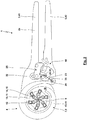
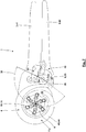
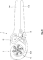
- Fig. 1 shows a crimping pliers 1 in a representation in which one of two cover plates 2a, 2b, with which a solid hand lever 3 and a pliers head 4, in particular a kind of "housing" of the pliers head 4, is disassembled.
- the pressing tongs 1 is formed with a fixed hand lever 3 and a movable hand lever 5.
- a pivoting of the hand lever 3, 5 towards each other via a drive mechanism 6 and a spring element 7, which forms a force-displacement compensating element 8, a relative movement of actuators 9, 10.
- the actuator 9 is integral with the part of the cover plate 2, which extends in the region of the pliers head 4 formed so that it is a fixed actuator 9 here.
- the actuating element 10 is designed as a movable actuating element 10 in the form of a pivot ring 11, which relative to the fixed actuating element 9 to the vertical to the plane according to Fig.
- the dies 12 are pivotable about axes which are oriented parallel to the die axis 13, mounted opposite bearing pin 14, which are held on the actuating element 9 and the cover plate 2.
- the pivot pin 11 thus forms guides 15 for the dies 12.
- the pivot ring 11 forms radially inwardly in the region of grooves actuating surfaces 16 on which abutment surfaces 17 of the dies 12 abut such that a pivoting of the pivot ring 11 about the Gesenkachse 13 pivoting the dies 12 has around the bearing pin 14 result.
- This pivoting of the dies 12 in turn has the consequence that a die contour 18 formed by the dies 12, which is closed in the circumferential direction about the die axis 13 with the formation of minimal gaps between the adjacent dies 12, changes in size.
- the die contour 18 is formed hexagonal regardless of the size thereof in the first approximation.
- the spring element 7 is formed by an integral projection of the swivel ring 11, which extends in a circular arc or here in a spiral around the swage axis 13 in the circumferential direction.
- the circumferential angle is approximately 360 °, wherein the formed in the connection region with the pivot ring 11 Federfußdazzling 19 and the outer Federfußddling 20 of the spring element 7 approximately in a 4:00 clock position with respect to the Gesenkachse 13 as shown in FIG Fig. 1 are arranged with horizontally oriented fixed lever 3.
- the Federfußddling 20 is pivotable, here via a bearing pin 21, hinged to the movable hand lever 5.
- a roller 23 is rotatably mounted.
- the roller 23 is located on a curved path 24 of a guide member 25.
- the guide member 25 performs the roller 23 only on one side about the curved path 24, while for a different embodiment, a recording of the roller 23 between two curved paths can be done, which with a Game or no game can be the case.
- the guide member 25 is rigid, here via bearing pins 26, 27, fixed to the fixed hand lever 3.
- the bearing pin 22 is also pivotally mounted a Sperrveriereungslander 28, which is formed with lifting parts 29, 30.
- the lever part 29 forms a locking toothing 31.
- the lever member 30 has a radially oriented to the bearing pin 22 slot 32 through which the bearing pin 27 passes.
- the drive mechanism 6 is designed as a toggle mechanism 33. This has a toggle lever 34, which corresponds to the connection between the point of contact of the roller 23 with the guide track 24, and a second toggle lever 35, which the connection between the bearing pins 21, 22 predetermined bearing axes corresponds. Between the toggle levers 34, 35 a knee angle 36 is formed.
- a pivoting of the locking toothed lever 28 is accompanied, during which a locking lug 39 of a pawl 40, which is also supported by a spring 93 pivotally mounted on the hand lever 5, ratchet-like along the ratchet teeth 31 slides. If the hand forces applied to the hand levers 3, 5 are temporarily reduced or eliminated, the engagement of the locking nose 39 in the locking toothing 31 blocks the opening movement of the hand levers 3, 5 and thus also the opening movement of the dies 12.
- the spring element 7 is formed here as a kind of bending beam 43.
- force components in the circumferential direction 37 and / or in the radial direction 38 are introduced into this bending beam 43, which stresses the bending beam 43 about a bending axis which is vertical to the plane of the drawing Fig. 1 is oriented.
- a stress of the bending beam 43 with a compressive force on buckling.
- the bending beam 43 is subjected to a tensile force in the circumferential direction 37.
- the bending beam 43 is in accordance with a in the drawing plane Fig. 1 extending spiral spring or circular arc spring 44 is formed.
- the spiral or circular arc spring extends in the circumferential direction 37 about the Gesenkachse 13.
- the bending beam 43 in this case has a circular arc-shaped or spiral-shaped neutral fiber or longitudinal axis 45, along which the bending stiffness changes, in particular by a change in the area moment of inertia.
- the design of the height of the cross section of the bending beam 43 which determines the area moment of inertia, symmetrical to an axis of symmetry, which passes through the Gesenkachse 13 and the Federfußddling 20. Accordingly, the height and the cross-sectional area of the spring element 7 is maximally in a cross-section 47, which is arranged centrally between the spring base points 19, 20 in the circumferential direction.
- the pressing tongs with two cover plates 2a, 2b is formed.
- the two cover plates 2a, 2b on the one hand form the fixed hand lever 3.
- the cover plates 2a, 2b form a kind of housing of the pliers head 4, between which the moving parts, namely the spring element 7, the Swivel ring 11 and the dies 12 are added.
- the bearing pins 14 of the dies 12 are received in bores 49 of the cover plates 2a, 2b.
- the spring element 7 and the swivel ring 11 are formed in plate construction, here with four plates, wherein the individual plates for the swivel ring 11 and the spring element 7 are formed in one piece.
- the spring element on its outer side a projection 50 in which a spring base 51 or a coupled with such a Federfußtician tappet another spring 52 is supported, the other Federfußddling 53 is supported on the cover plates 2a, 2b or the movable hand lever 5.
- the force relationships on the pressing tongs 1 can be influenced in addition to the spring element 7.
- the additional spring 52 can serve to influence the dependence of the generated pressing force on the pivoting angle of the hand lever and the actuating force applied to the hand lever. It is also possible that the contact pressure of the roller 23 on the guide track 24 of the guide member 25 is increased or ensured by the further spring 52.
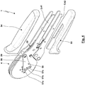
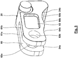
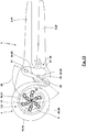
- Fig. 4 shows the assembled basic components of the pressing tongs 1 according to Fig. 3 before its assembly with the two hand levers 3, 5 associated with handles 54, 55th
- the pressing tongs 1 can have a positioning device 56.
- the positioning device 56 has three alternative receptacles 57a, 57b, 57c for workpieces with different cross-sectional areas for the illustrated embodiment.
- the positioning device 56 can be brought into different operating positions in which in each case a receptacle 57 a (57 b, 57 c) is arranged coaxially to the die axis 13.
- the positioning device 56 is formed with a Positionierstrebe or positioning washer 58 which is pivotally mounted on the cover plates 2, here by means of a bearing pin 59.
- the Positionierstrebe or positioning washer 58 lies directly sliding on the outside of the cover plate 2b.
- the guide member 25 may be fork-shaped with the formation of a slot 60 between two legs 61a, 61b. Through the slot 60 of the guide member 25 extends to allow a relative pivoting movement of the Sperrveriereungshebel 28 (see also Fig. 3 ).
- the legs 61a, 61b each have a bore 62a, 62b, through which the bearing pin 27 extends in the installed state.
- the legs 61a, 61b may have recesses 63.
- Fig. 5 It can be seen that for the illustrated embodiment, two parallel cam tracks 24a, 24b are formed by the two legs 61a, 61b, at which then two rollers 23a, 23b roll on both sides of the locking gear lever 28. Furthermore, it can be seen that the cam tracks 24a, 24b for the illustrated embodiment have two concave portions 64, 65, between which a convex portion 66 is disposed.
- the curved path 24 in the concave portion 65 which is traversed at the beginning of the power stroke, more inclined than other portions of the curved path 24th
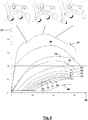
- Fig. 8 the applied hand forces 67 are shown as a function of the actuation path 68 of the movable hand lever 5.
- the curves 69 to 81 show the hand force curves for different cross sections of the workpieces, namely 0.08 mm 2 (69), 0.14 mm 2 (70), 0.25 mm 2 (71), 0.35 mm 2 (72 ), 0.5 mm 2 (73), 0.75 mm 2 (74), 1.0 mm 2 (75), 1.5 mm 2 (76) 2.5 mm 2 (77), 4 mm 2 ( 78), 6 mm 2 (79), 10 mm 2 (80) and 16 mm (81).
- Fig. 9 is shown for the spring element 7 an exemplary choice of dimensions. It can be seen here that the spring element extends in a spiral shape around the die axis 13 with a circumferential angle of approximately 360 °.
- the effective height 82 of the spring element 7 for influencing the area moment of inertia is symmetrical to the axis of symmetry 46 and increases from both Federfußddlingen 19, 20 to the same extent to the middle of the spring element 7 in the circumferential direction between the two Federfußddlingen 19, 20. While in Fig. 9 only discrete values of the height 82 of the spring element 7 are indicated, shows Fig. 10 the dependence of the height 82 from the circumferential angle 83, starting from the point centrally between the two spring base points 19, 20th
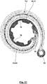
- Figure 11 shows the stress distribution in the spring element 7, wherein the same gray levels are used for equal voltages here.
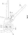
- the toggle mechanism 33 is not formed with a roller 23 and a cam track 24 of a guide member 25.
- a pressure lever 83 which forms the knee joint 84 in the region of the bearing pin 22 and is articulated in an end region via a bearing pin 27 on the cover plate 2.
- the other end region of the pressure lever 83 directly forms the locking teeth 31 of the Zwangsgesperres 48.
- the knee angle 36 about 90 °, which starting from the open position not immediately large pressing forces can be generated while in the closed position according to Fig. 13 a knee angle 36 of about 160, 165 or 170 ° is reached, for which thus high pressing forces can be generated at the end of the power stroke.
- the knee angle 36 increases continuously with the passage of the power stroke (while for the use of the principle roller 23 / curved path 24 according to Fig. 1 to 11 depending on the selected contour of the curved path 24 is quite possible that the knee angle 24 is smaller during the passage of the power stroke in at least a portion or remains constant).
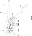
- Fig. 14 shows a further embodiment of a pressing tongs 1, wherein according to the embodiment, in Fig. 12 and 13 is shown, a pressure lever 83 without roller / cam track is used.
- Fig. 15 shows a further embodiment in which a circular arc spring 44 extends between the spring base points 19, 20 only over a circumferential angle of approximately 90 °. Furthermore, the circular arc spring 44 is not oriented here exclusively in the circumferential direction about the Gesenkachse 13, which under certain circumstances results in a modified type of stress of the circular arc spring 44. Put simply, in this case, the circular arc spring 44 can be understood as a curved resilient "strut", which acts tangentially on the pivot ring 11.
- the spring element 7 and the spiral or circular arc spring 44 extends over a circumferential angle of about 180 °.
- an embodiment with pressure lever 83 instead of the principle of roller 23 / cam 24, an embodiment with pressure lever 83 use.
- the pressure lever 83 is not rigid, but deliberately yielding, so that this embodiment integrates the measures according to the non-prepublished European patent application EP 14 154 206.8 into the pressing tongs.
- the pressure lever 83 forms the locking teeth 31 in one end region.
- the pressure lever is formed in a rough approximation V-shaped or curved or arcuate formed with a bow angle in the range of 150 to 180 °.
- Fig. 17 shows a further embodiment of the pressing tongs 1 according to the invention with a pressure lever 83 which is formed here without locking teeth 31 and has a greater extent in direct articulation of the pressure lever 83 to the two hand lever 3, 5th
- the embodiment according to Fig. 18 basically corresponds to the embodiment according to Fig. 12 , However, here is another transfer of the movement of the actuating element 10 or pivot ring 11 on the dies 12: In this case, only two opposing dies 12a, 12b are present.
- the dies 12a, 12b are also guided here by guides 15, wherein the guide is not carried out for a pivoting movement of the dies 12a, 12b, but for a translational movement of the dies 12a, 12b towards and away from each other.
- a cause of the movement of the dies 12a, 12b along the predetermined by the guides 15 degrees of freedom is also effected here by a contact of actuating surfaces 16 of the pivot ring 11 with counter-actuating surfaces 17 of the dies 12a, 12b. While in Fig. 18 the pressing tongs 1 is shown in an open position, shows Fig. 19 the closed position of the pressing tongs. 1
- Fig. 20 shows an embodiment of a pressing tongs 1 without the use of a toggle mechanism 33. Rather, here is the movable hand lever 5 pivotally mounted directly on the cover plate 2 and thus the fixed hand lever 3.
- the Federfußddling 20 of the spring element 7 is articulated directly to an over the pivot point of the hand lever 5 on the hand lever 3 protruding end portion of the hand lever 5, which takes place here via a bearing pin 87 of the spring element 7, which is received in a slot 88 of the hand lever 5.
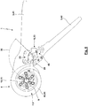
- Fig. 21 shows a further embodiment of the pressing tongs 1, which basically in the Fig. 1 to 11 illustrated embodiment corresponds. However, here the contour of the guideway 24 is selected such that it has exclusively concave portion 64, 65, which are connected to each other via a rectilinear portion 89.
- Fig. 22 and 23 show a further embodiment of a pressing tongs, wherein Fig. 22 the pressing tongs in the open position with mounted cover plate shows and Fig. 23 the pressing tongs also in the open position, but without mounted cover plate shows.
- This embodiment basically corresponds to the embodiment of the pressing tongs 1 according to FIG Fig. 1 to 11 or Fig. 21 ,
- the spring element 7 is guided with an additional guide 90.
- the guide 90 is formed by a spring pin 7 supported by the guide pin 91, which is guided in a guide groove or a slot 92 of the cover plates 2.
- the slot 92 extends circumferentially around the die axis 13.
- the guide member 25 is fixed to the fixed hand lever 3, while the roller 23 is rotatably supported relative to the movable hand lever 5. But it is also possible that the guide member 25 is fixed to the movable hand lever 5, while the roller 23 is rotatably mounted relative to the fixed hand lever 3.
- the same basic structure is used, being then used in the manually operated pressing tongs as drive elements hand lever, while for the power-operated pressing tongs instead of the hand lever to an actuator deflected drive elements are used.
- the fixed (hand) lever may also be shortened and supported on a fixed abutment, while on the movable (also shorter) (hand) Lever a connecting rod, a plunger o. ⁇ . Of the actuator is articulated.
- UU is a power-operated crimping pliers trained without Zwangsgesperre.
Claims (22)
- Pince de pression (1) destinée à presser une pièce, aveca) deux éléments d'entraînement (41, 42) qui sont constitués en tant que levier manuel (3) fixe et levier manuel (5) mobile,b) une tête de pince (4),c) deux éléments d'actionnement (9, 10) disposés dans la zone de la tête de pince (4) qui actionnent deux matrices (12) entre lesquelles la pièce peut être pressée, etd) un élément à ressort (7) quida) est disposé dans le flux de force entre les éléments d'entraînement (41, 42) et les matrices (12) etdb) forme un élément de compensation force-déplacement (8),e) l'élément à ressort (7) formant l'élément de compensation force-déplacement (8) étant disposé dans la zone de la tête de pince (4),caractérisée en ce que
l'élément à ressort (7) avec un point de pied de ressort (20) est articulé de façon pivotante sur le levier manuel (5) mobile. - Pince de pression (1) selon la revendication 1, caractérisée en ce quea) il existe un mécanisme d'entraînement (6) qui est intercalé entre les éléments d'entraînement (41, 42) et les éléments d'actionnement (9, 10), etb) l'élément à ressort (7) est intercalé dans le flux de force entre le mécanisme d'entraînement (6) et les éléments d'actionnement (9, 10).
- Pince de pression (1) selon la revendication 1 ou 2, caractérisée en ce qu'un point de pied de ressort (19) de l'élément à ressort (7) est fixé sur un des éléments d'actionnement (10).
- Pince de pression (1) selon l'une des revendications précédentes, caractérisée en ce que l'élément à ressort (7) est constitué en tant que barre flexible (43).
- Pince de pression (1) selon la revendication 4, caractérisée en ce que l'élément à ressort (7) est constitué en plaque.
- Pince de pression (1) selon l'une des revendications précédentes, caractérisée en ce que l'élément à ressort (7) s'étend autour d'un axe de matrice (13) dans la direction circonférentielle.
- Pince de pression (1) selon la revendication 6, caractérisée en ce que l'élément à ressort (7) est constitué en tant que ressort en arc de cercle ou en tant que ressort hélicoïdal (44).
- Pince de pression (1) selon l'une des revendications 4 à 7, caractérisée en que la barre flexible (43) possède une rigidité à la flexion qui varie dans la direction de son axe longitudinal (45).
- Pince de pression selon la revendication 8, caractérisée en ce que le moment d'inertie géométrique de la barre flexible (43) augmente à partir du point de pied de ressort (20) sur lequel s'effectue l'action exercée par le mécanisme d'entraînement (6) vers une section transversale (46) de la barre flexible (43) opposée à ce point de pied de ressort (20) dans la direction circonférentielle.
- Pince de pression selon la revendication 9, caractérisée en ce que le moment d'inertie géométrique de la barre flexible (43) est symétrique par rapport à un axe de symétrie (46) qui traverse approximativement le point de pied de ressort (20) sur lequel s'effectue l'action exercée par le mécanisme d'entraînement et la section transversale (47) de la barre flexible (43) opposée à ce point de pied de ressort (20) dans la direction circonférentielle.
- Pince de pression (1) selon l'une des revendications précédentes, caractérisée en ce quea) un élément d'actionnement (9) présente des guidages (15) pour des matrices (12), etb) un élément d'actionnement (10) présente des surfaces d'actionnement (16) pour les matrices (12),c) un mouvement relatif des éléments d'actionnement (9, 10) entraîne un mouvement des matrices (12) relativement aux guidages (15) qui est provoqué par le contact des surfaces d'actionnement (16) avec les matrices (12).
- Pince de pression (1) selon l'une des revendications précédentes, caractérisée en ce quea) les éléments d'actionnement (9, 10) sont pivotés relativement les uns aux autres autour de l'axe de matrice (13),b) les matrices (12) sont supportées de façon pivotante par rapport aux guidages (15), etc) le pivotement relatif des éléments d'actionnement (9, 10) entraîne un pivotement des matrices (12) relativement aux guidages (15) qui est provoqué par le contact des surfaces d'actionnement (16) avec les matrices (12).
- Pince de pression (1) selon l'une des revendications précédentes, caractérisée en ce que le mécanisme d'entraînement (6) est formé avec un mécanisme de levier à genouillère (33).
- Pince de pression (1) selon la revendication 13, caractérisée en ce que le mécanisme de levier à genouillère (33) est formé avec un rouleau (23) et une partie de guidage (25), le rouleau (23) roulant sur la partie de guidage (25) en parcourant la course de travail.
- Pince de pression (1) selon la revendication 14, caractérisée en ce quea) la partie de guidage (25) est fixée sur un élément d'entraînement (41) sur lequel est fixé un élément d'actionnement (9), etb) le rouleau (23) est supporté de façon rotative sur l'autre élément d'entraînement (42) sur lequel l'élément à ressort (7) raccordé à l'autre élément d'actionnement (10) est articulé.
- Pince de pression (1) selon la revendication 14 ou 15, caractérisée en ce qu'il existe un autre élément à ressort (52) qui fournit une force de pression du rouleau (23) sur la partie de guidage (25).
- Pince de pression (1) selon la revendication 16, caractérisée en ce qu'un point de pied de ressort de l'autre élément à ressort (52) agit sur l'élément à ressort (7).
- Pince de pression (1) selon l'une des revendications précédentes, caractérisée en ce qu'il existe un blocage forcé (48).
- Pince de pression selon la revendication 18, caractérisée en ce que le blocage forcé (48) est formé avec un levier à denture de blocage (28),a) qui est supporté de façon rotative autour de l'axe de rotation du rouleau (23), etb) dont une zone d'extrémité opposée à la denture de blocage (31) est raccordée, par le biais d'un trou oblong (32), à l'élément d'entraînement (41) sur lequel est fixée la partie de guidage (25).
- Pince de pression (1) selon l'une des revendications précédentes, caractérisée en ce que, avec la pince de pression (1), en utilisanta) la compensation force-déplacement du fait de l'élément de compensation force-déplacement (8) et/oub) le mouvement du rouleau (23) le long de la trajectoire courbe (24) de la partie de guidage (25) avec une variation des relations de grandeur et d'angle du mécanisme de levier à genouillère (33),des pièces avec différentes surfaces de section transversale à presser peuvent être pressées, les surfaces de section transversale différant les unes des autres d'au moins le facteur 30 pour deux pièces différentes pouvant être pressées avec la pince de pression.
- Pince de pression (1) selon l'une des revendications précédentes, caractérisée en ce que, sur la tête de pince (4), il est disposé un équipement de positionnement (56) pour au moins une pièce.
- Pince de pression selon l'une des revendications précédentes, caractérisée en ce que l'élément à ressort (7) est guidé par le biais d'un guidage (90).
Priority Applications (5)
| Application Number | Priority Date | Filing Date | Title |
|---|---|---|---|
| EP14189548.2A EP3012923B1 (fr) | 2014-10-20 | 2014-10-20 | Pince de pression |
| TW104134186A TWI667107B (zh) | 2014-10-20 | 2015-10-19 | 擠壓鉗以及利用一擠壓鉗擠壓一工作物的方法 |
| JP2015206104A JP6609455B2 (ja) | 2014-10-20 | 2015-10-20 | プレスプライヤ |
| CN201510684896.4A CN105522535B (zh) | 2014-10-20 | 2015-10-20 | 挤压钳 |
| US14/887,549 US9634451B2 (en) | 2014-10-20 | 2015-10-20 | Crimping pliers |
Applications Claiming Priority (1)
| Application Number | Priority Date | Filing Date | Title |
|---|---|---|---|
| EP14189548.2A EP3012923B1 (fr) | 2014-10-20 | 2014-10-20 | Pince de pression |
Publications (2)
| Publication Number | Publication Date |
|---|---|
| EP3012923A1 EP3012923A1 (fr) | 2016-04-27 |
| EP3012923B1 true EP3012923B1 (fr) | 2017-11-29 |
Family
ID=51730449
Family Applications (1)
| Application Number | Title | Priority Date | Filing Date |
|---|---|---|---|
| EP14189548.2A Active EP3012923B1 (fr) | 2014-10-20 | 2014-10-20 | Pince de pression |
Country Status (5)
| Country | Link |
|---|---|
| US (1) | US9634451B2 (fr) |
| EP (1) | EP3012923B1 (fr) |
| JP (1) | JP6609455B2 (fr) |
| CN (1) | CN105522535B (fr) |
| TW (1) | TWI667107B (fr) |
Cited By (2)
| Publication number | Priority date | Publication date | Assignee | Title |
|---|---|---|---|---|
| EP3904006A1 (fr) | 2020-04-28 | 2021-11-03 | WEZAG GmbH & Co. KG | Matrice de pince à sertir et pince à sertir |
| EP3904007A1 (fr) | 2020-04-28 | 2021-11-03 | WEZAG GmbH & Co. KG | Matrice de pince à sertir et pince à sertir |
Families Citing this family (17)
| Publication number | Priority date | Publication date | Assignee | Title |
|---|---|---|---|---|
| USD838564S1 (en) * | 2015-03-02 | 2019-01-22 | Phoenix Contact Gmbh & Co. Kg | Tool |
| US11541514B2 (en) | 2016-03-23 | 2023-01-03 | Milwaukee Electric Tool Corporation | Locking pliers |
| CN106607953B (zh) * | 2016-11-30 | 2018-07-17 | 保定曼德汽车配件有限公司 | 环切刀具 |
| US10513012B2 (en) * | 2017-02-13 | 2019-12-24 | Brett Womack | Adjustable socket |
| EP3396796B1 (fr) | 2017-04-25 | 2021-07-21 | WEZAG GmbH & Co. KG | Outil de compression, de sertissage ou de découpe et module d'outils |
| WO2019051491A1 (fr) | 2017-09-11 | 2019-03-14 | Milwaukee Electric Tool Corporation | Pinces de verrouillage à section de mâchoire mobile augmentant le couple |
| EP3656504B1 (fr) * | 2018-11-20 | 2022-02-23 | WEZAG GmbH & Co. KG | Outil de moulage, ensemble d'outil de moulage, réseau d'outils de moulage et procédé de moulage d'une pièce à usiner |
| JP7326451B2 (ja) * | 2019-01-24 | 2023-08-15 | ブロックワイズ エンジニアリング エルエルシー | 半径方向圧縮機械 |
| USD910395S1 (en) | 2019-03-11 | 2021-02-16 | Milwaukee Electric Tool Corporation | Pliers |
| EP3820001B1 (fr) | 2019-11-11 | 2022-08-17 | WEZAG GmbH & Co. KG | Pince à sertir et groupe de pinces à sertir |
| EP3834989B1 (fr) | 2019-12-11 | 2022-11-23 | WEZAG GmbH & Co. KG | Outil pince à main et procédé de montage d'un tel outil |
| CN111029878B (zh) * | 2020-01-03 | 2021-06-18 | 张静贤 | 一种电机碳刷弹簧套入器 |
| US20210331293A1 (en) * | 2020-04-28 | 2021-10-28 | Zhejiang Vasung Tools Co., Ltd. | Crimping pliers |
| US11111962B1 (en) * | 2020-07-16 | 2021-09-07 | Schaeffler Technologies AG & Co. KG | Bearing with an integrated electrical shunt |
| USD1000238S1 (en) * | 2021-06-15 | 2023-10-03 | Cembre S.P.A. | Crimping tool |
| EP4243222A1 (fr) | 2022-03-09 | 2023-09-13 | WEZAG GmbH & Co. KG | Capteur de puissance de pince à sertir et pince à sertir |
| KR102521631B1 (ko) * | 2022-09-15 | 2023-04-13 | 하현철 | 수직 하향식 내면 연속 유압 압착기 |
Family Cites Families (28)
| Publication number | Priority date | Publication date | Assignee | Title |
|---|---|---|---|---|
| US2079498A (en) * | 1934-06-28 | 1937-05-04 | Harry A Douglas | Compressing tool |
| US3226968A (en) * | 1963-08-14 | 1966-01-04 | Gen Dynamics Corp | Crimping tool |
| US3459029A (en) * | 1967-02-28 | 1969-08-05 | Buchanan Electric Products Cor | Adjustable crimping tool |
| US4381661A (en) | 1980-03-19 | 1983-05-03 | C. A. Weidmuller Gmbh & Co. | Tool having two working jaws |
| SE441484B (sv) | 1984-02-27 | 1985-10-07 | Pressmaster Tool Ab | Klemverktyg |
| AU110321S (en) * | 1990-06-01 | 1991-02-13 | Alba Ind Ltd | Crimping tool |
| US5261263A (en) * | 1992-12-21 | 1993-11-16 | Whitesell Eric J | Crimping pliers with radially opposed jaws |
| DE19507347C1 (de) | 1995-03-02 | 1996-09-12 | Rennsteig Werkzeuge Gmbh | Preßzange für Aderendhülsen |
| US5918511A (en) * | 1997-08-28 | 1999-07-06 | Board Of Supervisors Of Louisiana State University And Agricultural And Mechanical College | Adjustable socket wrench |
| DE19963097C5 (de) * | 1999-12-24 | 2017-04-27 | Wezag Gmbh Werkzeugfabrik | Zange zum Verpressen eines Werkstücks |
| DE10140270B4 (de) | 2001-08-16 | 2004-09-30 | Wezag Gmbh Werkzeugfabrik | Presszange zum Einpressen mehrerer Kerben auf dem Umfang eines Kontaktelementes |
| US6629443B2 (en) * | 2002-01-16 | 2003-10-07 | Yen Chao Chin | Ergonomic crimping apparatus |
| US6941844B2 (en) * | 2003-11-10 | 2005-09-13 | Jeffrey B. Hile | Self-adjusting locking pliers |
| US6889579B1 (en) * | 2004-01-23 | 2005-05-10 | Loggerhead Tools Llc | Adjustable gripping tool |
| DE102005003615B3 (de) | 2005-01-26 | 2006-09-21 | Wezag Gmbh Werkzeugfabrik | Presszange zum Einpressen mehrerer Kerben auf dem Umfang eines Kontaktelementes |
| CN2860746Y (zh) * | 2005-11-30 | 2007-01-24 | 田�健 | 料带连接钳 |
| SE529618C2 (sv) * | 2006-02-21 | 2007-10-09 | Pressmaster Ab | Länk för krimpverktyg |
| SE529617C2 (sv) * | 2006-02-21 | 2007-10-09 | Pressmaster Ab | Klämback och krimpverktyg |
| DE102007056262A1 (de) * | 2007-04-24 | 2008-11-06 | Rennsteig Werkzeuge Gmbh | Hand-Zangenwerkzeug |
| TW201008714A (en) * | 2008-07-02 | 2010-03-01 | Rennsteig Werkzeuge Gmbh | Crimping tool |
| DE102009008197A1 (de) * | 2009-02-02 | 2010-08-12 | Wiha Werkzeuge Gmbh | Zange |
| DE202009005811U1 (de) * | 2009-04-18 | 2010-09-16 | Weidmüller Interface GmbH & Co. KG | Crimpwerkzeug |
| DE102009026470A1 (de) * | 2009-05-26 | 2010-12-09 | Rennsteig Werkzeuge Gmbh | Verfahren zur Überwachung des Verschleißes einer Handzange und Vorrichtung hierfür |
| US9142931B2 (en) * | 2010-02-18 | 2015-09-22 | Tyco Electronics Corporation | Crimp tool with cam actuated crimp jaw |
| DE202012102561U1 (de) * | 2012-07-11 | 2013-10-14 | Weidmüller Interface GmbH & Co. KG | Crimpwerkzeug für Aderendhülsen |
| DE102013100801A1 (de) * | 2013-01-28 | 2014-07-31 | Rennsteig Werkzeuge Gmbh | Crimpzange |
| EP2826598B1 (fr) | 2013-07-17 | 2016-12-28 | Wezag GmbH Werkzeugfabrik | Outil de presse avec dispositif limiteur d'une force de pressage mecanique |
| EP2905848B1 (fr) | 2014-02-06 | 2016-09-14 | Wezag GmbH Werkzeugfabrik | Pince de pression |
-
2014
- 2014-10-20 EP EP14189548.2A patent/EP3012923B1/fr active Active
-
2015
- 2015-10-19 TW TW104134186A patent/TWI667107B/zh active
- 2015-10-20 CN CN201510684896.4A patent/CN105522535B/zh active Active
- 2015-10-20 US US14/887,549 patent/US9634451B2/en active Active
- 2015-10-20 JP JP2015206104A patent/JP6609455B2/ja active Active
Non-Patent Citations (1)
| Title |
|---|
| None * |
Cited By (4)
| Publication number | Priority date | Publication date | Assignee | Title |
|---|---|---|---|---|
| EP3904006A1 (fr) | 2020-04-28 | 2021-11-03 | WEZAG GmbH & Co. KG | Matrice de pince à sertir et pince à sertir |
| EP3904007A1 (fr) | 2020-04-28 | 2021-11-03 | WEZAG GmbH & Co. KG | Matrice de pince à sertir et pince à sertir |
| US11631957B2 (en) | 2020-04-28 | 2023-04-18 | Wezag Gmbh & Co. Kg | Crimping pliers die and crimping pliers |
| US11967795B2 (en) | 2020-04-28 | 2024-04-23 | Wezag Gmbh & Co. Kg | Crimping pliers die and crimping pliers |
Also Published As
| Publication number | Publication date |
|---|---|
| TWI667107B (zh) | 2019-08-01 |
| TW201628794A (zh) | 2016-08-16 |
| US9634451B2 (en) | 2017-04-25 |
| JP6609455B2 (ja) | 2019-11-20 |
| EP3012923A1 (fr) | 2016-04-27 |
| JP2016078234A (ja) | 2016-05-16 |
| US20160111841A1 (en) | 2016-04-21 |
| CN105522535A (zh) | 2016-04-27 |
| CN105522535B (zh) | 2018-11-23 |
Similar Documents
| Publication | Publication Date | Title |
|---|---|---|
| EP3012923B1 (fr) | Pince de pression | |
| EP3012924B1 (fr) | Pince de pression | |
| EP2905848B1 (fr) | Pince de pression | |
| DE102008012011B3 (de) | Zangenkopf | |
| EP2873122B1 (fr) | Outil de sertissage pour douille d'extrêmité de conducteur | |
| DE3109289C2 (fr) | ||
| EP2562891B1 (fr) | Pince de pression | |
| EP1922787B1 (fr) | Outil de double sertissage | |
| EP2463969A2 (fr) | Tête de pince pour une pince de sertissage | |
| EP3208044A1 (fr) | Pince comprenant un systeme de levier a genouillere | |
| EP2082837A1 (fr) | Pince à sertir | |
| EP3904007B1 (fr) | Matrice de pince à sertir et pince à sertir | |
| DE102018121971A1 (de) | Presswerkzeug | |
| EP2930797B1 (fr) | Outil de sertissage à réglage automatique | |
| EP0490066A2 (fr) | Pince pour sertir des embouts | |
| EP3553900A1 (fr) | Mâchoire pivotante de pince du type à plaques et pince de sertissage pourvue de mâchoire pivotante de pince | |
| EP3718179A1 (fr) | Pince-étau | |
| EP3096423A1 (fr) | Pince à dénuder | |
| EP3553899A1 (fr) | Outil de sertissage | |
| EP3834989B1 (fr) | Outil pince à main et procédé de montage d'un tel outil | |
| EP2921260B1 (fr) | Appareil à entraînement pneumatique | |
| DE102008007303A1 (de) | Spreizzange | |
| DE102016100940A1 (de) | Motorisch betätigbare Schere | |
| EP3904006B1 (fr) | Matrice de pince à sertir et pince à sertir | |
| EP2672584A1 (fr) | Outil de montage de connecteur solaire |
Legal Events
| Date | Code | Title | Description |
|---|---|---|---|
| PUAI | Public reference made under article 153(3) epc to a published international application that has entered the european phase |
Free format text: ORIGINAL CODE: 0009012 |
|
| AK | Designated contracting states |
Kind code of ref document: A1 Designated state(s): AL AT BE BG CH CY CZ DE DK EE ES FI FR GB GR HR HU IE IS IT LI LT LU LV MC MK MT NL NO PL PT RO RS SE SI SK SM TR |
|
| AX | Request for extension of the european patent |
Extension state: BA ME |
|
| 17P | Request for examination filed |
Effective date: 20160926 |
|
| RBV | Designated contracting states (corrected) |
Designated state(s): AL AT BE BG CH CY CZ DE DK EE ES FI FR GB GR HR HU IE IS IT LI LT LU LV MC MK MT NL NO PL PT RO RS SE SI SK SM TR |
|
| REG | Reference to a national code |
Ref country code: DE Ref legal event code: R079 Ref document number: 502014006389 Country of ref document: DE Free format text: PREVIOUS MAIN CLASS: H01R0043042000 Ipc: B21J0007160000 |
|
| GRAP | Despatch of communication of intention to grant a patent |
Free format text: ORIGINAL CODE: EPIDOSNIGR1 |
|
| RIC1 | Information provided on ipc code assigned before grant |
Ipc: H01R 43/042 20060101ALI20170629BHEP Ipc: B21J 7/16 20060101AFI20170629BHEP |
|
| INTG | Intention to grant announced |
Effective date: 20170802 |
|
| GRAS | Grant fee paid |
Free format text: ORIGINAL CODE: EPIDOSNIGR3 |
|
| GRAA | (expected) grant |
Free format text: ORIGINAL CODE: 0009210 |
|
| AK | Designated contracting states |
Kind code of ref document: B1 Designated state(s): AL AT BE BG CH CY CZ DE DK EE ES FI FR GB GR HR HU IE IS IT LI LT LU LV MC MK MT NL NO PL PT RO RS SE SI SK SM TR |
|
| REG | Reference to a national code |
Ref country code: CH Ref legal event code: EP |
|
| REG | Reference to a national code |
Ref country code: AT Ref legal event code: REF Ref document number: 949915 Country of ref document: AT Kind code of ref document: T Effective date: 20171215 |
|
| REG | Reference to a national code |
Ref country code: IE Ref legal event code: FG4D Free format text: LANGUAGE OF EP DOCUMENT: GERMAN |
|
| REG | Reference to a national code |
Ref country code: CH Ref legal event code: NV Representative=s name: RIEDERER HASLER AND PARTNER PATENTANWAELTE AG, CH |
|
| REG | Reference to a national code |
Ref country code: DE Ref legal event code: R096 Ref document number: 502014006389 Country of ref document: DE |
|
| REG | Reference to a national code |
Ref country code: SE Ref legal event code: TRGR |
|
| REG | Reference to a national code |
Ref country code: NL Ref legal event code: MP Effective date: 20171129 |
|
| REG | Reference to a national code |
Ref country code: LT Ref legal event code: MG4D |
|
| PG25 | Lapsed in a contracting state [announced via postgrant information from national office to epo] |
Ref country code: LT Free format text: LAPSE BECAUSE OF FAILURE TO SUBMIT A TRANSLATION OF THE DESCRIPTION OR TO PAY THE FEE WITHIN THE PRESCRIBED TIME-LIMIT Effective date: 20171129 Ref country code: FI Free format text: LAPSE BECAUSE OF FAILURE TO SUBMIT A TRANSLATION OF THE DESCRIPTION OR TO PAY THE FEE WITHIN THE PRESCRIBED TIME-LIMIT Effective date: 20171129 Ref country code: NO Free format text: LAPSE BECAUSE OF FAILURE TO SUBMIT A TRANSLATION OF THE DESCRIPTION OR TO PAY THE FEE WITHIN THE PRESCRIBED TIME-LIMIT Effective date: 20180228 Ref country code: ES Free format text: LAPSE BECAUSE OF FAILURE TO SUBMIT A TRANSLATION OF THE DESCRIPTION OR TO PAY THE FEE WITHIN THE PRESCRIBED TIME-LIMIT Effective date: 20171129 |
|
| PG25 | Lapsed in a contracting state [announced via postgrant information from national office to epo] |
Ref country code: BG Free format text: LAPSE BECAUSE OF FAILURE TO SUBMIT A TRANSLATION OF THE DESCRIPTION OR TO PAY THE FEE WITHIN THE PRESCRIBED TIME-LIMIT Effective date: 20180228 Ref country code: HR Free format text: LAPSE BECAUSE OF FAILURE TO SUBMIT A TRANSLATION OF THE DESCRIPTION OR TO PAY THE FEE WITHIN THE PRESCRIBED TIME-LIMIT Effective date: 20171129 Ref country code: GR Free format text: LAPSE BECAUSE OF FAILURE TO SUBMIT A TRANSLATION OF THE DESCRIPTION OR TO PAY THE FEE WITHIN THE PRESCRIBED TIME-LIMIT Effective date: 20180301 Ref country code: LV Free format text: LAPSE BECAUSE OF FAILURE TO SUBMIT A TRANSLATION OF THE DESCRIPTION OR TO PAY THE FEE WITHIN THE PRESCRIBED TIME-LIMIT Effective date: 20171129 Ref country code: RS Free format text: LAPSE BECAUSE OF FAILURE TO SUBMIT A TRANSLATION OF THE DESCRIPTION OR TO PAY THE FEE WITHIN THE PRESCRIBED TIME-LIMIT Effective date: 20171129 |
|
| PG25 | Lapsed in a contracting state [announced via postgrant information from national office to epo] |
Ref country code: NL Free format text: LAPSE BECAUSE OF FAILURE TO SUBMIT A TRANSLATION OF THE DESCRIPTION OR TO PAY THE FEE WITHIN THE PRESCRIBED TIME-LIMIT Effective date: 20171129 |
|
| PG25 | Lapsed in a contracting state [announced via postgrant information from national office to epo] |
Ref country code: CZ Free format text: LAPSE BECAUSE OF FAILURE TO SUBMIT A TRANSLATION OF THE DESCRIPTION OR TO PAY THE FEE WITHIN THE PRESCRIBED TIME-LIMIT Effective date: 20171129 Ref country code: EE Free format text: LAPSE BECAUSE OF FAILURE TO SUBMIT A TRANSLATION OF THE DESCRIPTION OR TO PAY THE FEE WITHIN THE PRESCRIBED TIME-LIMIT Effective date: 20171129 Ref country code: SK Free format text: LAPSE BECAUSE OF FAILURE TO SUBMIT A TRANSLATION OF THE DESCRIPTION OR TO PAY THE FEE WITHIN THE PRESCRIBED TIME-LIMIT Effective date: 20171129 Ref country code: CY Free format text: LAPSE BECAUSE OF FAILURE TO SUBMIT A TRANSLATION OF THE DESCRIPTION OR TO PAY THE FEE WITHIN THE PRESCRIBED TIME-LIMIT Effective date: 20171129 Ref country code: DK Free format text: LAPSE BECAUSE OF FAILURE TO SUBMIT A TRANSLATION OF THE DESCRIPTION OR TO PAY THE FEE WITHIN THE PRESCRIBED TIME-LIMIT Effective date: 20171129 |
|
| REG | Reference to a national code |
Ref country code: DE Ref legal event code: R097 Ref document number: 502014006389 Country of ref document: DE |
|
| PG25 | Lapsed in a contracting state [announced via postgrant information from national office to epo] |
Ref country code: RO Free format text: LAPSE BECAUSE OF FAILURE TO SUBMIT A TRANSLATION OF THE DESCRIPTION OR TO PAY THE FEE WITHIN THE PRESCRIBED TIME-LIMIT Effective date: 20171129 Ref country code: PL Free format text: LAPSE BECAUSE OF FAILURE TO SUBMIT A TRANSLATION OF THE DESCRIPTION OR TO PAY THE FEE WITHIN THE PRESCRIBED TIME-LIMIT Effective date: 20171129 Ref country code: SM Free format text: LAPSE BECAUSE OF FAILURE TO SUBMIT A TRANSLATION OF THE DESCRIPTION OR TO PAY THE FEE WITHIN THE PRESCRIBED TIME-LIMIT Effective date: 20171129 Ref country code: IT Free format text: LAPSE BECAUSE OF FAILURE TO SUBMIT A TRANSLATION OF THE DESCRIPTION OR TO PAY THE FEE WITHIN THE PRESCRIBED TIME-LIMIT Effective date: 20171129 |
|
| PG25 | Lapsed in a contracting state [announced via postgrant information from national office to epo] |
Ref country code: MT Free format text: LAPSE BECAUSE OF FAILURE TO SUBMIT A TRANSLATION OF THE DESCRIPTION OR TO PAY THE FEE WITHIN THE PRESCRIBED TIME-LIMIT Effective date: 20171129 |
|
| PLBE | No opposition filed within time limit |
Free format text: ORIGINAL CODE: 0009261 |
|
| STAA | Information on the status of an ep patent application or granted ep patent |
Free format text: STATUS: NO OPPOSITION FILED WITHIN TIME LIMIT |
|
| REG | Reference to a national code |
Ref country code: FR Ref legal event code: PLFP Year of fee payment: 5 |
|
| 26N | No opposition filed |
Effective date: 20180830 |
|
| PG25 | Lapsed in a contracting state [announced via postgrant information from national office to epo] |
Ref country code: SI Free format text: LAPSE BECAUSE OF FAILURE TO SUBMIT A TRANSLATION OF THE DESCRIPTION OR TO PAY THE FEE WITHIN THE PRESCRIBED TIME-LIMIT Effective date: 20171129 |
|
| GBPC | Gb: european patent ceased through non-payment of renewal fee |
Effective date: 20181020 |
|
| REG | Reference to a national code |
Ref country code: BE Ref legal event code: MM Effective date: 20181031 |
|
| PG25 | Lapsed in a contracting state [announced via postgrant information from national office to epo] |
Ref country code: MC Free format text: LAPSE BECAUSE OF FAILURE TO SUBMIT A TRANSLATION OF THE DESCRIPTION OR TO PAY THE FEE WITHIN THE PRESCRIBED TIME-LIMIT Effective date: 20171129 Ref country code: LU Free format text: LAPSE BECAUSE OF NON-PAYMENT OF DUE FEES Effective date: 20181020 |
|
| REG | Reference to a national code |
Ref country code: IE Ref legal event code: MM4A |
|
| PG25 | Lapsed in a contracting state [announced via postgrant information from national office to epo] |
Ref country code: BE Free format text: LAPSE BECAUSE OF NON-PAYMENT OF DUE FEES Effective date: 20181031 |
|
| PG25 | Lapsed in a contracting state [announced via postgrant information from national office to epo] |
Ref country code: GB Free format text: LAPSE BECAUSE OF NON-PAYMENT OF DUE FEES Effective date: 20181020 Ref country code: IE Free format text: LAPSE BECAUSE OF NON-PAYMENT OF DUE FEES Effective date: 20181020 |
|
| PG25 | Lapsed in a contracting state [announced via postgrant information from national office to epo] |
Ref country code: TR Free format text: LAPSE BECAUSE OF FAILURE TO SUBMIT A TRANSLATION OF THE DESCRIPTION OR TO PAY THE FEE WITHIN THE PRESCRIBED TIME-LIMIT Effective date: 20171129 |
|
| PG25 | Lapsed in a contracting state [announced via postgrant information from national office to epo] |
Ref country code: PT Free format text: LAPSE BECAUSE OF FAILURE TO SUBMIT A TRANSLATION OF THE DESCRIPTION OR TO PAY THE FEE WITHIN THE PRESCRIBED TIME-LIMIT Effective date: 20171129 |
|
| PG25 | Lapsed in a contracting state [announced via postgrant information from national office to epo] |
Ref country code: MK Free format text: LAPSE BECAUSE OF NON-PAYMENT OF DUE FEES Effective date: 20171129 Ref country code: HU Free format text: LAPSE BECAUSE OF FAILURE TO SUBMIT A TRANSLATION OF THE DESCRIPTION OR TO PAY THE FEE WITHIN THE PRESCRIBED TIME-LIMIT; INVALID AB INITIO Effective date: 20141020 |
|
| PG25 | Lapsed in a contracting state [announced via postgrant information from national office to epo] |
Ref country code: AL Free format text: LAPSE BECAUSE OF FAILURE TO SUBMIT A TRANSLATION OF THE DESCRIPTION OR TO PAY THE FEE WITHIN THE PRESCRIBED TIME-LIMIT Effective date: 20171129 Ref country code: IS Free format text: LAPSE BECAUSE OF FAILURE TO SUBMIT A TRANSLATION OF THE DESCRIPTION OR TO PAY THE FEE WITHIN THE PRESCRIBED TIME-LIMIT Effective date: 20180329 |
|
| REG | Reference to a national code |
Ref country code: AT Ref legal event code: MM01 Ref document number: 949915 Country of ref document: AT Kind code of ref document: T Effective date: 20191020 |
|
| PG25 | Lapsed in a contracting state [announced via postgrant information from national office to epo] |
Ref country code: AT Free format text: LAPSE BECAUSE OF NON-PAYMENT OF DUE FEES Effective date: 20191020 |
|
| REG | Reference to a national code |
Ref country code: DE Ref legal event code: R082 Ref document number: 502014006389 Country of ref document: DE Representative=s name: REHBERG HUEPPE + PARTNER PATENTANWAELTE PARTG , DE Ref country code: DE Ref legal event code: R081 Ref document number: 502014006389 Country of ref document: DE Owner name: WEZAG GMBH & CO. KG, DE Free format text: FORMER OWNER: WEZAG GMBH WERKZEUGFABRIK, 35260 STADTALLENDORF, DE |
|
| REG | Reference to a national code |
Ref country code: CH Ref legal event code: PFA Owner name: WEZAG GMBH AND CO. KG, DE Free format text: FORMER OWNER: WEZAG GMBH WERKZEUGFABRIK, DE |
|
| PGFP | Annual fee paid to national office [announced via postgrant information from national office to epo] |
Ref country code: SE Payment date: 20231025 Year of fee payment: 10 Ref country code: FR Payment date: 20231023 Year of fee payment: 10 Ref country code: DE Payment date: 20230713 Year of fee payment: 10 Ref country code: CH Payment date: 20231102 Year of fee payment: 10 |