EP3012534A2 - Haushaltsgerätevorrichtung - Google Patents
Haushaltsgerätevorrichtung Download PDFInfo
- Publication number
- EP3012534A2 EP3012534A2 EP15189939.0A EP15189939A EP3012534A2 EP 3012534 A2 EP3012534 A2 EP 3012534A2 EP 15189939 A EP15189939 A EP 15189939A EP 3012534 A2 EP3012534 A2 EP 3012534A2
- Authority
- EP
- European Patent Office
- Prior art keywords
- main component
- circuit board
- printed circuit
- appliance device
- mounted state
- Prior art date
- Legal status (The legal status is an assumption and is not a legal conclusion. Google has not performed a legal analysis and makes no representation as to the accuracy of the status listed.)
- Granted
Links
Images


Classifications
-
- F—MECHANICAL ENGINEERING; LIGHTING; HEATING; WEAPONS; BLASTING
- F24—HEATING; RANGES; VENTILATING
- F24C—DOMESTIC STOVES OR RANGES ; DETAILS OF DOMESTIC STOVES OR RANGES, OF GENERAL APPLICATION
- F24C7/00—Stoves or ranges heated by electric energy
- F24C7/08—Arrangement or mounting of control or safety devices
-
- F—MECHANICAL ENGINEERING; LIGHTING; HEATING; WEAPONS; BLASTING
- F24—HEATING; RANGES; VENTILATING
- F24C—DOMESTIC STOVES OR RANGES ; DETAILS OF DOMESTIC STOVES OR RANGES, OF GENERAL APPLICATION
- F24C15/00—Details
- F24C15/10—Tops, e.g. hot plates; Rings
- F24C15/102—Tops, e.g. hot plates; Rings electrically heated
- F24C15/104—Arrangements of connectors, grounding, supply wires
Definitions
- the invention relates to a household appliance device according to the preamble of patent claim 1.
- a household appliance device with an electrically conductive main component which is designed as a housing component and which has an electrically conductive contact region, is already known from the prior art.
- the household appliance device further comprises a printed circuit board, which is fastened in an assembled state to the main component, by means of screw connections.
- the printed circuit board and the main component are connected to each other by a flexible conduit element in the form of a cable.
- This duct element is fastened to the main component by means of screws, whereby a contact is made.
- the line element at one of the circuit boards facing the end of a cable lug which is coupled in the mounted state with a corresponding connection element of the circuit board.
- the object of the invention is in particular to provide a generic household appliance device with an advantageously low complexity.
- the object is achieved by the features of claim 1, while advantageous embodiments and modifications of the invention can be taken from the dependent claims.
- the invention relates to a household appliance device, in particular a cooktop device, with at least one at least partially, in particular at least a large part, advantageously at least substantially and preferably completely electrically conductive main component, which is advantageously designed differently from a particular flexible conduit element such as a cable and which has at least one fastening element and at least one grounding contact element, and with at least one printed circuit board, which in at least one mounted state on the at least one main component via the at least one fastening element in particular indirectly and / or advantageously directly attached and which has at least one conductor track, which is electrically connected to produce an electrical ground with the at least one grounding contact element.
- a "household appliance device” is to be understood as meaning, in particular, at least one part, in particular a subassembly, of a household appliance, in particular a cooktop.
- the household appliance device may also comprise the entire household appliance, in particular the entire hob.
- a home appliance comprising the household appliance device is to be referred to in particular as a white goods and advantageously provided to facilitate a household work at least partially a user and / or remove.
- the domestic appliance is advantageous from an entertainment device, which is to be designated in particular as a brown goods, designed differently.
- electrically conductive is meant in particular an electrical conductivity of at least 10 -3 S / m, advantageously of at least 1 S / m, more preferably of at least 10 3 S / m and preferably of at least 10 6 S / m at 20 ° C. become.
- a "main component” is to be understood in particular as a component which has at least one extension, advantageously at least two extensions, which in particular have a value of at least 50%, advantageously at least 60%, particularly advantageously at least 70%, preferably at least 80%.
- an "extension" of a component is to be understood in particular a length of a side edge of a smallest imaginary cuboid, which just completely surrounds the component.
- the at least one main component could in particular comprise at least one electrically conductive material and be advantageously formed from at least one electrically conductive material, such as metal, in particular rolled metal and / or sheet steel. It is also conceivable that at least a main component in particular has at least one electrically insulating material and is advantageously made of at least one electrically insulating material, which in particular carries at least one electrically conductive coating, which is preferably arranged at least in the at least one contact region.
- the at least one electrically insulating material could in this case in particular be formed by a plastic and / or a ceramic.
- an “at least partially electrically conductive" main component is to be understood in particular to mean a main component which has at least one partial region, in particular at least one surface region, which is designed to be electrically conductive.
- a “fastening element" of a component should in particular be understood to mean a partial region of the component which is intended to be mechanically contacted to produce a fastening between the component and at least one further component, and advantageously a shape suitable for the production of the fastening has a connection to at least one fastening means.
- a "ground contact element" of a component should in particular be understood as an at least partially electrically conductive element, which is provided in the at least one mounted state, advantageously indirectly and / or directly an electrically conductive connection with at least one further component, in particular with the at least To produce a circuit board to advantageously achieve grounding of at least one component involved in the connection.
- the at least one grounding contact element could form a surface area of the at least one main component arranged at least substantially in one plane.
- the at least one ground contact element could alternatively or additionally also be formed by a surface region of the at least one main component which is formed at least partially as a thread.
- the at least one grounding contact element could alternatively or additionally, for example, form an at least partially protruding out of a plane surface area of the at least one main component, such as a projection and / or a protrusion and / or depression and / or unevenness and / or a rough surface area.
- a "printed circuit board” is to be understood in particular as meaning a component which, in the at least one assembled state, forms a particularly electrical connection of electrical components and / or advantageous for a particular mechanical attachment of electrical components is provided and advantageously carries a weight of the electrical components at least to a large extent and / or to another component, such as the at least one main component forwards.
- the electrical components can in this case in particular be designed in various ways, such as, for example, by electrical components and / or by electrical conductor tracks.
- the at least one printed circuit board is advantageously formed from at least a large part of at least one insulating material, wherein different materials are conceivable, such as FR1, FR2, FR3, FR4, FR5, CEM-1, CEM-3 and / or Teflon.
- a "grounding” is to be understood in particular as meaning an electrically conductive connection by means of which a connection to a ground potential, in particular to an electrically conductive component having an electrical potential of at least substantially 0 V, and / or preferably to an electrical potential of a ground is.
- the at least one fastening element and the at least one ground contact element are "at least partially" integrally formed, it should be understood that the at least one fastening element forms at least a portion of the at least one ground contact element and / or that the at least one ground contact element at least one Part of the at least one fastening element is formed.
- one piece should be understood in particular at least materially connected connected, for example, by a welding process, a gluing process, a Anspritzrind and / or another, the skilled person appear useful process, and / or advantageously formed in one piece, such as by a Manufacture from a casting and / or by a production in a one- or multi-component injection molding process and advantageously from a single blank.
- intended is intended to be understood in particular specially designed and / or equipped. The fact that an object is intended for a specific function should in particular mean that the object fulfills and / or executes this specific function in at least one application and / or operating state.
- advantageously low complexity can be achieved.
- low costs can be achieved and / or rapid assembly can be made possible.
- Particularly advantageous may be a number of electrical Components are reduced, whereby in particular a reliable grounding and / or a low susceptibility to ground fault can be achieved.
- a high stability can be achieved, in particular in the form of a high mechanical strength and / or a high mechanical rigidity.
- high electromagnetic compatibility and / or high safety against electrical discharge can be achieved.
- relevant standards can advantageously be met.
- the at least one printed circuit board could be earthed, wherein a grounding of the at least one main component could take place via the at least one printed circuit board, which in this case could be connected to a grounding line of a main line element.
- the at least one main component is grounded.
- a "grounded" component is to be understood in particular as meaning a component which in particular has an electrical potential of essentially 0 V and / or preferably an electrical potential of a ground and which advantageously has an electrically conductive connection to at least one further component, in particular the electric potential of substantially 0 V and / or preferably, the electric potential of the soil dictates mandatory.
- the grounded component is in particular forced by the electrically conductive connection to the at least one further component, in particular the electrical potential of substantially 0 V and / or preferably the electrical potential of the ground.
- This advantageously complies with the CISPR14 and IEC55014 standards. In particular, high electromagnetic compatibility and / or high safety against electrical discharge can be achieved.
- the at least one main component is designed as a housing component.
- a “housing component” is to be understood in particular as a component which, in the at least one assembled state, forms at least a major part of an outer boundary of at least one cavity and which at least partially forms an outer boundary of the at least one cavity which is provided at least in one Operating state to record at least one unit and / or at least one element in particular of the domestic appliance, such as an operating unit and / or a control unit and / or a heating element and / or a Supply electronics and / or an energy source.
- the housing component By the use of the housing component "at least partially" forming an outer boundary of the at least one cavity, it should be understood in particular that the housing component has a proportion of at least 10%, in particular of at least 20%, advantageously of at least 30%, particularly advantageously of at least 40% and preferably at least 50% of an area fraction of the outer boundary of the at least one cavity is formed. As a result, in particular a high stability can be achieved.
- the at least one fastening element has at least one contact region with which the at least one printed circuit board can be brought into abutment in at least one mounted state for producing the grounding.
- a "contact region" of a component is to be understood in particular as meaning a surface region of the component which is provided, in particular in the at least one mounted state, advantageously indirectly and / or directly by mechanical connection with at least one further component, in particular with the at least one printed circuit board. and at least partially contacting the at least one further component, in particular when the grounding is produced, and / or on which at least one further component is advantageously applied when grounding is produced in order to particularly advantageously achieve grounding of at least one component participating in the connection.
- the at least one contact region can form a surface region of the at least one fastening element arranged at least essentially in one plane.
- the at least one contact region could form an at least partially protruding out of the plane surface portion of the at least one fastener, such as a projection and / or a protrusion and / or a bump and / or a rough surface area.
- the at least one printed circuit board in the at least one mounted state with the at least one contact area for making the ground "is engageable” should be understood in particular that the at least one circuit board has at least one surface area, in the at least an assembled state at least partially contacts the at least one contact region, in particular over a surface area of at least 0.25 cm 2 , advantageously of at least 0.5 cm 2 and preferably of at least 1 cm 2 .
- This can in particular a high stability be achieved, in particular in the form of a high mechanical strength and / or a high mechanical rigidity.
- the at least one fastening element is designed as a projection and rises in the at least one mounted state beyond a main plane of the at least one main component.
- the at least one projection is in particular a subregion of the at least one main component and advantageously has a surface region which projects beyond the main plane of the at least one main component by a distance of at least 2 mm, in particular of at least 3 mm and advantageously of at least 4 mm.
- the at least one printed circuit board is advantageously fastened to the at least one main component via the at least one projection.
- a "main plane" of a component is to be understood in particular as a plane which is defined by at least 50%, in particular by at least 60%, advantageously by at least 70% and preferably by at least 75% of a total mass of the component.
- the household appliance device comprises at least one further main component, which is arranged in the at least one mounted state at least largely between the at least one main component and the at least one printed circuit board.
- the at least one further main component “at least for the most part” is arranged between the at least one main component and the at least one printed circuit board, it should be understood in particular that in the at least one assembled state and when viewed in a plan view, the at least one further main component over a proportion of at least 70%, advantageously of at least 80%, and preferably of at least 85% of a surface, which is located in the at least one mounted state between the at least one main component and the at least one printed circuit board.
- the at least one main component could in particular comprise at least one electrically insulating material and be advantageously formed from at least one electrically insulating material, wherein the at least one electrically insulating material in this case in particular by a ceramic and / or advantageous by a Plastic, in particular a thermoplastic material, such as polypropylene PP and / or polyamide PA, in particular PA6 and / or PA6 / 6, could be formed.
- the at least one further main component in particular has at least one electrically conductive material and is advantageously made of at least one electrically conductive material, which in particular carries at least one electrically insulating coating. This can be made possible in particular a high stability.
- a high level of safety against electrical discharge can be achieved.
- the at least one fastening element in the at least one mounted state at least partially reach through the at least one further main component.
- the at least one fastening element in the at least one mounted state "at least partially" passes through the at least one further main component
- the at least one fastening element in the at least one mounted state is in particular in the at least one further main component engages and / or particularly advantageous passes through the at least one further main component, in particular to a mass fraction and / or volume fraction of at least one fastener of at least 50%, preferably at least 70%, more preferably at least 80% and preferably at least 90 %. This can be achieved in particular a high stability and / or high security.
- the at least one printed circuit board could, for example, rest at least partially on the at least one fastening element in the at least one assembled state, wherein a majority of a weight force of the at least one printed circuit board could be carried by the at least one fastening element in the at least one assembled state.
- the at least one further main component preferably has at least one support element on the surface of which at least partially rests at least one printed circuit board in the at least one assembled state, wherein in particular a majority of a weight force of the at least one printed circuit board in the at least one mounted state of the at least one Support element is worn.
- first component in the at least one mounted state on a surface of a second component "at least partially" rests, should in particular be understood that a mass fraction and / or a surface portion of the first component of at least 5%, in particular of at least 7% and advantageously of at least 10% rests on the surface of the second component.
- a first component at least partially “rests" on a surface of a second component in the at least one mounted state
- at least one surface portion of the first component contacts the surface of the second component and preferably a weight force of the first component in the at least one mounted state and in an installed position is at least partially supported by the second component, wherein a force flow is directed in particular from the first component via the surface to the second component.
- the at least one printed circuit board has a main extension plane, which in the at least one mounted state has a distance of at least 2 mm, in particular at least 3 mm, advantageously at least 3.5 mm and preferably at least 4 mm to a main plane of the has at least one other main component.
- a "main extension plane" of a structural unit is to be understood in particular to mean a plane which is parallel to a largest side surface of a smallest geometric cuboid which just completely surrounds the structural unit, and in particular runs through the center of the cuboid.
- the at least one fastening element could in particular have an at least substantially rough surface, which is recognizable in particular when viewed with the naked eye.
- the at least one fastening element alternatively or additionally has at least one protrusion which is provided to ensure contact in the at least one mounted state between the at least one grounding contact element and at least one surface subregion of the at least one printed circuit board.
- a "survey" is to be understood in particular a partial region of the at least one fastening element, which has a main plane of the at least one Fastener protrudes, in particular at least 0.1 mm, at least 0.2 mm, preferably at least 0.3 mm and preferably at least 0.5 mm.
- the at least one elevation advantageously compensates for manufacturing tolerances which could occur, in particular, in the case of a substantially smooth surface of the at least one fastening element and a substantially smooth surface of the at least one printed circuit board.
- the earthing in the at least one assembled state takes place only via components that are different from cables and preferably at least substantially rigid, wherein the at least one ground contact element, in particular indirectly with the at least one printed circuit board, advantageously via at least one of a cable different, and preferably at least essentially rigid component is connected.
- the ground in the at least one mounted state the earthing could advantageously be produced via at least one fastening means, such as a screw and / or a rivet and / or a bolt.
- the production of the earthing in the at least one assembled state could advantageously take place via at least one spacer element, such as, for example, a washer and / or a nut.
- Fig. 1 shows a household appliance 32 a, which is designed as a hob, with a household appliance device 10 a, which is designed as a hob device.
- the Domestic appliance device 10a comprises a main body 34a. In an assembled state, the main body 34a forms part of an outer housing, in particular an outer housing of the household appliance 32a.
- the main body 34a is formed as a plate, such as + front panel and / or cover plate of the household appliance.
- the main body 34a is designed as a hob plate and provided for setting up cooking utensils.
- the household appliance device 10a comprises a plurality of heating elements (not shown), which are each provided to heat on the base body 34a above the heating elements set up cooking utensils.
- the household appliance device 10a comprises an operating unit 36a for input and / or selection of operating parameters, for example a heating power and / or a heating power density and / or a heating zone.
- the operation unit 36a is provided for outputting a value of an operation parameter to an operator.
- the household appliance device 10a comprises a control unit 38a which is provided to execute actions and / or to change settings in dependence on operating parameters entered by means of the operating unit 36a.
- the control unit 38a controls a power supply to the heating elements in a heating operation state.
- the control unit 38a controls a power supply of the household appliance device 10a in order to supply the activated heating elements with electric current.
- the household appliance device 10a comprises at least one electrical line (not shown), which is intended for transporting electric current.
- the electrical line could be formed for example by a cable, a wire and / or a stranded wire.
- the household appliance device 10a comprises a partially electrically conductive main component 12a (cf. Fig. 2 ).
- the main component 12a is designed as a housing component.
- the main member 12a forms part of the outer case.
- the main member 12a and the main body 34a are fixed to each other (not shown).
- the main body 34a forms in the mounted state and in the installed position an operator facing part of the outer housing.
- the main component 12a forms in the assembled state and in the installed position an operator facing away from the outer housing.
- the main body 34a and the main component 12a form a cavity in which components of the household appliance device 10a are arranged.
- the main component 12a has a plurality of fastening elements 18a.
- the main component 12a could have a different number of fasteners.
- a number of fasteners depending on a configuration of the household appliance is selected. In the following, only one of the fastening elements 18a will be described.
- the fastening element 18a has a contact region 14a.
- the fastening element 18a is intended for fastening components, in particular electrical components.
- the main component 12a has a plurality of ground contact elements 70a.
- a number of ground contact elements 70a and a number of fasteners 18a are identical. Alternatively, the main component could have different numbers of ground contact elements and / or fasteners. In the following, only one of the ground contact elements 70a will be described.
- the ground contact element 70a is provided for making the ground.
- the ground contact element 70a is partially electrically conductive.
- the ground contact element 70a is part of an electrically conductive connection necessary for grounding.
- the fastening element 18a and the grounding contact element 70a are partially formed in one piece.
- the household appliance device 10a comprises a plurality of printed circuit boards 16a (cf. Fig. 4 ), of which only one will be described below.
- the printed circuit board could be formed as a single-layer printed circuit board.
- the circuit board could be formed as a two-layer and / or multi-layer circuit board.
- the printed circuit board 16a serves as a carrier for the electrical components.
- a filter and the power supply are arranged on the printed circuit board.
- the printed circuit board 16a can be brought into contact with the contact region 14a in the assembled state for establishing a ground.
- the printed circuit board 16a has a conductor track which contacts the contact region 14a of the fastening element 18a.
- the ground contact element 70a and the contact region 14a are partially formed in one piece.
- the main member 12a is grounded in the assembled state.
- the main component 12a is connected to a neutral of a main terminal (not shown).
- the main connection is used to supply power to all components and / or components of the household appliance.
- the fastener 18a is formed as a projection and rises in the assembled state beyond a main plane of the main member 12a. With respect to an embodiment and / or a shape of the fastening element, various embodiments are conceivable.
- the fastening element could have a substantially U-shaped form, wherein legs of the fastening element could in particular be aligned substantially perpendicular to the main plane of the main component.
- the fastening element 18a has two legs 40a and an intermediate piece 42a (cf. Fig. 3 ) connecting the two legs 40a to each other.
- the legs 40a are aligned obliquely relative to the main plane of the main member 12a.
- the intermediate piece 42a forms a main plane of the fastening element 18a.
- the main plane of the fastener 18a and the main plane of the main member 12a are arranged substantially parallel to each other.
- the main component 12a and the fastening element 18a are partially formed in one piece.
- the main member 12a and the ground contact member 70a are formed integrally in part.
- the fastener 18a is partially electrically conductive.
- the fastening element 18a forms the contact region 14a of the main component 12a.
- the intermediate piece 42a of the fastening element 18a forms the contact region 14a of the main component 12a.
- the earthing is made via the earthing contact element 70a.
- the printed circuit board 16a is fastened to the main component 12a via the fastening element 18a (cf. Fig. 4 and 5 ).
- the fastening element 18a has a fastening recess 44a, via which an attachment of the printed circuit board 16a to the fastening element 18a takes place.
- the printed circuit board 16a is fastened to the fastening element 18a by means of a fastening means 46a.
- the fastening means 46a partially engages in the fastening recess 44a.
- the fastener 46a is shown as a screw.
- the fastener 18a has a portion which forms a thread.
- the Thread is arranged on a lateral boundary of the fastening recess 44a.
- the fastener 46a is engaged with the thread.
- the household appliance device 10a comprises a further main component 20a (cf. Fig. 3 to 5 ).
- the further main component 20a is largely arranged in the assembled state between the main component 12a and the printed circuit board 16a.
- the further main component 20a has a main plane, which in the mounted state is aligned substantially parallel to the main plane of the main component 12a. In the mounted state, the further main component 20a forms a bottom of the cavity enclosed by the outer housing.
- the further main component 20a is integrally formed.
- the other main component 20a is attached to the main component 12a.
- An attachment of the further main component 20a to the main component 12a takes place in a method for mounting the household appliance device 10a prior to attachment of the printed circuit board 16a to the main component 12a.
- the other main component could be detachably fastened to the main component and, in particular, detachable without tools.
- a permanent attachment of the other main component to the main component is conceivable.
- the further main component could be clamped between the side walls of the main component and / or held in a form-fitting manner.
- the further main component 20a is placed in the assembled state on the main component 12a, in particular on the main plane of the main component 12a.
- the fastening element 18a partially engages through the further main component 20a.
- the further main component 20a has a through-passage recess 48a, through which the fastening element 18a partially engages in the mounted state (cf. Fig. 3 and 5 ).
- the further main component 20a has a support element 22a.
- the support element 22a limits the passage recess 48a.
- the support member 22a defines the penetration recess 48a from three sides.
- the further main component 20a has a boundary wall 50a, which delimits the passage recess 48a from another side.
- the boundary wall 50a protrudes in the assembled state to a large extent beyond the main plane of the other main component 20a addition. A majority of the surfaces of the boundary wall 50a are aligned in the assembled state substantially perpendicular to the main plane of the other main component 20a.
- the support member 22a protrudes in the assembled state for the most part beyond the main plane of the other main component 20a addition. A majority of the surfaces of the support member 22a is aligned in the assembled state substantially perpendicular to the main plane of the other main component 20a.
- the support element 22a has a surface 24a which is aligned substantially parallel to the main plane of the further main component 20a (cf. Fig. 3 ). In the mounted state, the printed circuit board 16a lies partly on the surface 24a (cf. Fig. 4 and 5 ).
- the further main component 20a has at least one further support element 52a. In the present exemplary embodiment, the further main component 20a has a plurality of support elements 52a, of which only one will be described below.
- the further support member 52a has a surface 54a on which the circuit board 16a is partially disposed in the assembled state. A weight force of the printed circuit board 16a is supported by the other main component 20a in the assembled state and in the installation position. The further main component 20a forwards the weight of the printed circuit board 16a in the mounted state and in the installed position to the main component 12a.
- the further main component 20a is provided in the assembled state for avoiding unwanted electrical contact between the printed circuit board 16a and the partially electrically conductive main component 12a.
- the circuit board 16a has a main extension plane, which in the mounted state a distance from in the Substantially 4 mm to the main plane of the other main component 20a.
- the distance between the main plane of extension of the circuit board 16a and the main plane of the other main component 20a is chosen to avoid damaging electrical components attached to the circuit board 16a.
- the further main component 20a is arranged for electrical insulation between a majority of the main plane of the main component 12a and a majority of the main extension plane of the printed circuit board 16a and electrical components connected to the printed circuit board 16a. Surfaces of the further main component 20a are designed to be electrically insulating.
- the further main component 20a has a plurality of position holding elements 56a (cf. Fig. 4 and 5 ) securing, in the mounted state, a position of the circuit board 16a relative to the main plane of the main member 12a in a direction substantially perpendicular to the main plane of the main member 12a.
- the position holding members 56a are disposed in direct contact with a surface portion of the circuit board 16a.
- the position holding members 56a are elastically disposed on a side wall 58a of the main member 12a and movable relative to the side wall 58a.
- the further main component 20a could have exactly one position retaining element, wherein the printed circuit board could have electrically insulating surface subareas in order to avoid unwanted electrical contact with the main component.
- An electrically insulating surface portion of the printed circuit board 16a could in this case be arranged in an edge portion of the printed circuit board 16a in the mounted state, wherein a position half-element could be arranged in direct contact with the surface portion in the assembled state.
- a position of the circuit board 16a relative to the main member 12a in directions aligned substantially parallel to the main plane of the main member 12a is partially secured in the assembled state by the attachment of the circuit board 16a to the main member 12a.
- the further main component 20a has a plurality of further position retaining elements 60a which, in the assembled state, secure a position of the printed circuit board 16a relative to the main component 12a in directions aligned substantially parallel to the main plane of the main component 12a (cf. Fig. 4 ).
- the circuit board 16 a has recesses 62 a, which in peripheral areas of the Main extension plane of the circuit board 16 a are arranged. In each recess 62a of the circuit board 16a engages a further position retaining member 60a partially.
- the further main component has exactly one further position holding element, wherein the printed circuit board could have exactly one recess corresponding to the position holding element.
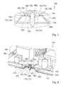
- FIG. 6 to 8 Further embodiments of the invention are shown. The following descriptions are essentially limited to the differences between the embodiments, with respect to the same components, features and functions on the description of the embodiment of Fig. 1 to 5 can be referenced. To distinguish the embodiments, the letter a in the reference numerals of the embodiment in the Fig. 1 to 5 by the letters b and c in the reference numerals of the embodiments of the Fig. 6 to 8 replaced. With respect to identically designated components, in particular with regard to components with the same reference numerals, can in principle also to the drawings and / or the description of the embodiment of Fig. 1 to 5 to get expelled.
- Fig. 6 shows a section of a cooking appliance designed as a household appliance 32b with a cooking appliance designed as a household appliance device 10b.
- the household appliance device 10b comprises an electrically conductive main component 12b, which has a fastening element 18b and a grounding contact element 70b, which are partially formed in one piece.
- the fastening element 18b has a contact region 14b.
- the household appliance device 10b comprises a printed circuit board 16b, which in a mounted state can be brought into contact with the contact region 14b for producing a grounding (cf. Fig. 7 ).
- the fastening element 18b is formed as a projection and rises in the assembled state beyond a main plane of the main component 12b (see. Fig. 6 ).
- the fastening element 18b Via the fastening element 18b, an attachment of the printed circuit board 16b to the main component 12b takes place in the mounted state.
- the grounding between the main component 12b and the printed circuit board 16b is made via the earth contact element 70b.
- the fastening element 18b has two elevations 26b, of which only one will be described below.
- the elevation 26b is arranged on one of the circuit board 16b in the mounted state facing surface side of the fastener s 18b.
- the circuit board 16b in the mounted state facing surface side of the fastener s 18b and the contact portion 14b of the fastener 18b are substantially identical, and in particular in a case of a substantially smooth surface of the fastener s 18b.
- the bump 26b in the assembled state, ensures contact between the contact portion 14b and a surface portion 28b of the circuit board 16b.
- the surface portion 28b is formed as a part of a wiring of the circuit board 16b.
- the contact portion 14b of the fastener 18b is partially formed by a surface of the protrusion 26b.
- the contact portion 14b is partially formed by the surface side of the fastener 18b facing the printed circuit board 16b in the assembled state.
- the ground contact member 70b is partially formed by the contact portion 14b.
- the ground contact element 70b is partially formed by the protrusion 26b.
- the surface portion 28b of the circuit board 16b is disposed on the protrusion 26b.
- a fastening means 46b which serves for a fastening between the printed circuit board 16b and the fastening element 18b, in the mounted state, a frictional connection between the fastening element 18b and the printed circuit board 16b is made.
- the fastening means 46b causes a deformation of the printed circuit board 16b and / or of the fastening element 18b in the mounted state. The deformation caused by the fastener 46b increases a contact area between the contact portion 14b and the surface portion 28b of the circuit board 16b.
- Fig. 8 shows a further embodiment of a cooking appliance designed as a household appliance 32c with a designed as a hob device household appliance device 10c.
- the household appliance device 10c comprises a partially electrically conductive main component 12c, which has a fastening element 18c and a grounding contact element 70c, which are formed partially in one piece.
- the fastening element 18c has a contact region 14c.
- the household appliance device 10c comprises a printed circuit board 16c, which in an assembled state can be brought into contact with the contact region 14c for establishing a grounding.
- a surface side of the printed circuit board 16c which faces the mounting element 18c of the main component 12c in the mounted state and which is in the form of a projection, is designed to be electrically insulating.
- the assembled Condition is one of the circuit board 16c facing surface side of the fastener s 18c arranged in contact with the fastening element 18c of the main component 12c facing surface side of the circuit board 16c.
- An attachment between the circuit board 16c and the fastening element 18c takes place in the mounted state via a fastening means 46c.
- the fastening element 18c has a fastening recess 44c.
- the fastening recess 44c is formed as a thread.
- the fastening means 46c partially engages in the mounted state in the fastening recess 44c of the fastening element 18c.
- the fastening means 46c is designed as a screw.
- the ground contact member 70c is formed by the fixing recess 44c.
- the ground contact element 70c is formed by the thread.
- the printed circuit board 16c has a further contact region 64c, which is designed to be electrically conductive.
- the further contact region 64c is arranged in the assembled state on a surface side of the printed circuit board 16c facing away from the fastening element 18c. In this case, the further contact region 64c in the mounted state is separated from the fastening element 18c by a base body of the printed circuit board 16c.
- the printed circuit board 16c has a conductor track, which forms the further contact region 64c.
- the further contact region 64c is formed as a part of the conductor track of the printed circuit board 16c.
- the grounding is carried out in the mounted state only via components 30c other than cables.
- a component 30c different from a cable is the fastening means 46c.
- the fastening means 46c has a first partial region 66c and a second partial region 68c.
- the first portion 66c has a screw head of the fastening means 46c designed as a screw
- the second portion 68c has a thread of the fastening means 46c.
- the first portion 66c is disposed in electrically conductive contact with the trace of the circuit board 16c.
- the first portion 66c is arranged in the mounted state in electrically conductive contact with the further contact region 64c of the circuit board 16c.
- the second portion 68 c is in the mounted state in electrically conductive contact with the at the lateral boundary of the Mounting recess 44c arranged thread.
- the second portion 68c is in the mounted state in electrically conductive contact with the ground contact element 70c.
- the earth contact element 70c is partially formed by the thread arranged at the lateral boundary of the attachment recess 44c.
- first partial area and a second partial area could be provided.
- the first subarea in the assembled state could be arranged in electrically conductive contact with the conductor track, in particular with the further contact region of the conductor track, and the second subarea in electrically conductive contact with the grounding contact element of the main component.
Landscapes
- Engineering & Computer Science (AREA)
- Chemical & Material Sciences (AREA)
- Combustion & Propulsion (AREA)
- Mechanical Engineering (AREA)
- General Engineering & Computer Science (AREA)
- Baking, Grill, Roasting (AREA)
- Shielding Devices Or Components To Electric Or Magnetic Fields (AREA)
- Food-Manufacturing Devices (AREA)
- Coupling Device And Connection With Printed Circuit (AREA)
- Electric Ovens (AREA)
- Cookers (AREA)
- Frying-Pans Or Fryers (AREA)
Abstract
Description
- Die Erfindung geht aus von einer Haushaltsgerätevorrichtung nach dem Oberbegriff des Patentanspruchs 1.
- Aus dem Stand der Technik ist bereits eine Haushaltsgerätevorrichtung mit einem elektrisch leitenden Hauptbauteil bekannt, das als Gehäusebauteil ausgebildet ist und das einen elektrisch leitenden Kontaktbereich aufweist. Die Haushaltsgerätevorrichtung umfasst zudem eine Leiterplatte, die in einem montierten Zustand an dem Hauptbauteil befestigt ist, und zwar mittels Schraubverbindungen. Zu einer Herstellung einer Erdung sind die Leiterplatte und das Hauptbauteil miteinander durch ein flexibles Leitungselement in Form eines Kabels verbunden. Dieses Leitungselement ist an dem Hauptbauteil mittels Schrauben befestigt, wodurch eine Kontaktierung hergestellt ist. Zu einer Kontaktierung des Leitungselements an der Leiterplatte weist das Leitungselement an einem der Leiterplatten zugewandten Ende einen Kabelschuh auf, der in dem montierten Zustand mit einem korrespondierenden Anschlusselement der Leiterplatte gekoppelt ist. Eine derartige Ausgestaltung ist einerseits aufwendig in der Montage und aufgrund der Verwendung mehrerer Bauteile kostenintensiv.
- Die Aufgabe der Erfindung besteht insbesondere darin, eine gattungsgemäße Haushaltsgerätevorrichtung mit einer vorteilhaft geringen Komplexität bereitzustellen. Die Aufgabe wird erfindungsgemäß durch die Merkmale des Patentanspruchs 1 gelöst, während vorteilhafte Ausgestaltungen und Weiterbildungen der Erfindung den Unteransprüchen entnommen werden können.
- Die Erfindung geht aus von einer Haushaltsgerätevorrichtung, insbesondere einer Kochfeldvorrichtung, mit zumindest einem wenigstens teilweise, insbesondere wenigstens zu einem Großteil, vorteilhaft wenigstens im Wesentlichen und vorzugsweise komplett elektrisch leitenden Hauptbauteil, welches vorteilhaft von einem insbesondere flexiblen Leitungselement wie beispielsweise einem Kabel verschieden ausgebildet ist und welches zumindest ein Befestigungselement und zumindest ein Erdungskontaktelement aufweist, und mit zumindest einer Leiterplatte, die in wenigstens einem montierten Zustand an dem zumindest einen Hauptbauteil über das zumindest eine Befestigungselement insbesondere mittelbar und/oder vorteilhaft unmittelbar befestigt ist und die zumindest eine Leiterbahn aufweist, welche zur Herstellung einer elektrischen Erdung mit dem zumindest einen Erdungskontaktelement elektrisch leitend verbunden ist.
- Es wird vorgeschlagen, dass das zumindest eine Befestigungselement und das zumindest eine Erdungskontaktelement wenigstens teilweise einstückig ausgebildet sind. Unter einer "Haushaltsgerätevorrichtung" soll insbesondere zumindest ein Teil, insbesondere eine Unterbaugruppe, eines Haushaltsgeräts, insbesondere eines Kochfelds, verstanden werden. Insbesondere kann die Haushaltsgerätevorrichtung auch das gesamte Haushaltsgerät, insbesondere das gesamte Kochfeld, umfassen. Ein die Haushaltsgerätevorrichtung umfassendes Haushaltsgerät ist insbesondere als Weiße Ware zu bezeichnen und vorteilhaft dazu vorgesehen, einem Benutzer eine Haushaltsarbeit wenigstens teilweise zu erleichtern und/oder abzunehmen. Das Hausgerät ist vorteilhaft von einem Unterhaltungsgerät, das insbesondere als Braune Ware zu bezeichnen ist, verschieden ausgebildet. Unter "elektrisch leitend" soll hier insbesondere eine elektrische Leitfähigkeit von mindestens 10-3 S/m, vorteilhaft von mindestens 1 S/m, besonders vorteilhaft von mindestens103 S/m und vorzugsweise von mindestens 106 S/m bei 20°C verstanden werden. Unter einem "Hauptbauteil" soll insbesondere ein Bauteil verstanden werden, das zumindest eine Erstreckung, vorteilhaft zumindest zwei Erstreckungen aufweist, die insbesondere einen Wert von mindestens 50 %, vorteilhaft von mindestens 60 %, besonders vorteilhaft von mindestens 70 %, vorzugsweise von mindestens 80 % und besonders bevorzugt von mindestens 90 % einer entsprechenden maximalen Erstreckung eines Endprodukts, insbesondere des Haushaltsgeräts, vorteilhaft des Kochfelds, beträgt und/oder das wenigstens wesentlich zu einer Gesamtmasse des Endprodukts, insbesondere des Haushaltsgeräts, vorteilhaft des Kochfelds, beiträgt und insbesondere einen Anteil von mindestens 5 %, vorteilhaft von mindestens 6 %, besonders vorteilhaft von mindestens 8 % und vorzugsweise von mindestens 10 % der Gesamtmasse des Endprodukts ausmacht. Unter einer "Erstreckung" eines Bauteils soll insbesondere eine Länge einer Seitenkante eines kleinsten gedachten Quaders verstanden werden, welcher das Bauteil gerade noch vollständig umschließt. Beispielsweise könnte das zumindest eine Hauptbauteil insbesondere wenigstens ein elektrisch leitfähiges Material aufweisen und vorteilhaft aus wenigstens einen elektrisch leitfähigen Material ausgebildet sein, wie beispielweise Metall, insbesondere Walzmetall und/oder Stahlblech. Ebenfalls denkbar ist, dass das zumindest eine Hauptbauteil insbesondere wenigstens ein elektrisch isolierendes Material aufweist und vorteilhaft aus wenigstens einen elektrisch isolierenden Material ausgebildet ist, welches insbesondere zumindest eine elektrisch leitfähige Beschichtung trägt, die vorzugsweise wenigstens in dem zumindest einen Kontaktbereich angeordnet ist. Das wenigstens eine elektrisch isolierende Material könnte hierbei insbesondere durch einen Kunststoff und/oder eine Keramik gebildet sein. Unter einem "wenigstens teilweise elektrisch leitenden" Hauptbauteil soll insbesondere ein Hauptbauteil verstanden werden, das zumindest einen Teilbereich, insbesondere zumindest einen Oberflächenbereich, aufweist, der elektrisch leitend ausgebildet ist. Unter einem "Befestigungselement" eines Bauteils soll insbesondere ein Teilbereich des Bauteils verstanden werden, der dazu vorgesehen ist, zu einer Herstellung einer Befestigung zwischen dem Bauteil und zumindest einem weiteren Bauteil mechanisch kontaktiert zu werden, und das vorteilhaft eine zu der Herstellung der Befestigung geeignete Gestalt zu einer Anbindung an wenigstens ein Befestigungsmittel aufweist. Als Befestigungsmittel sind verschiedene Möglichkeiten denkbar, wie beispielsweise eine Niete und/oder ein Bolzen und/oder eine Schraube und/oder ein an der Leiterplatte angeordnetes Rastelement und/oder ein an der Leiterplatte angeordneter Vorsprung, wie insbesondere in Form eines Stifts. Unter einem "Erdungskontaktelement" eines Bauteils soll insbesondere ein wenigstens teilweise elektrisch leitendes Element verstanden werden, das insbesondere in dem wenigstens einen montierten Zustand dazu vorgesehen ist, vorteilhaft mittelbar und/oder unmittelbar eine elektrisch leitende Verbindung mit zumindest einem weiteren Bauteil, insbesondere mit der zumindest einen Leiterplatte herzustellen, um vorteilhaft eine Erdung wenigstens eines an der Verbindung beteiligten Bauteils zu erreichen. Beispielsweise könnte das zumindest eine Erdungskontaktelement einen wenigstens im Wesentlichen in einer Ebene angeordneten Oberflächenbereich des zumindest einen Hauptbauteils ausbilden. Vorteilhaft könnte das zumindest eine Erdungskontaktelement alternativ oder zusätzlich auch von einem wenigstens teilweise als Gewinde ausgeformten Oberflächenbereich des zumindest einen Hauptbauteils gebildet sein. Das zumindest eine Erdungskontaktelement könnte alternativ oder zusätzlich beispielsweise einen wenigstens teilweise aus einer Ebene herausragenden Oberflächenbereich des zumindest einen Hauptbauteils ausbilden, wie beispielsweise einen Vorsprung und/oder eine Erhebung und/oder eine Vertiefung und/oder eine Unebenheit und/oder einen rauen Oberflächenbereich. Unter einer "Leiterplatte" soll insbesondere ein Bauteil verstanden werden, das in dem wenigstens einen montierten Zustand zu einer insbesondere elektrischen Verbindung von elektrischen Komponenten und/oder vorteilhaft zu einer insbesondere mechanischen Befestigung von elektrischen Komponenten vorgesehen ist und vorteilhaft eine Gewichtskraft der elektrischen Komponenten wenigstens zu einem Großteil trägt und/oder an ein weiteres Bauteil, wie beispielsweise das zumindest eine Hauptbauteil, weiterleitet. Die elektrischen Komponenten können hierbei insbesondere verschiedenartig ausgebildet sein, wie beispielsweise durch elektrische Bauteile und/oder durch elektrische Leiterbahnen. Die zumindest eine Leiterplatte ist vorteilhaft aus wenigstens zu einem Großteil aus zumindest einem isolierenden Material ausgebebildet, wobei verschiedene Materialien denkbar sind, wie beispielsweise FR1, FR2, FR3, FR4, FR5, CEM-1, CEM-3 und/oder Teflon. Unter einer "Erdung" soll insbesondere eine elektrisch leitfähige Verbindung verstanden werden, mittels welcher eine Verbindung zu einem Massepotential, insbesondere zu einem elektrisch leitfähigen Bauteil mit einem elektrischen Potential von wenigstens im Wesentlichen 0 V, und/oder vorzugsweise zu einem elektrischen Potential eines Erdbodens hergestellt ist. Unter der Wendung, dass das zumindest eine Befestigungselement und das zumindest eine Erdungskontaktelement "wenigstens teilweise" einstückig ausgebildet sind, soll insbesondere verstanden werden, dass das zumindest eine Befestigungselement wenigstens einen Teilbereich des zumindest einen Erdungskontaktelements ausbildet und/oder dass das zumindest eine Erdungskontaktelement wenigstens einen Teilbereich des zumindest einen Befestigungselements ausbildet. Unter "einstückig" soll insbesondere zumindest stoffschlüssig verbunden verstanden werden, beispielsweise durch einen Schweißprozess, einen Klebeprozess, einen Anspritzprozess und/oder einen anderen, dem Fachmann als sinnvoll erscheinenden Prozess, und/oder vorteilhaft in einem Stück geformt verstanden werden, wie beispielsweise durch eine Herstellung aus einem Guss und/oder durch eine Herstellung in einem Ein- oder Mehrkomponentenspritzverfahren und vorteilhaft aus einem einzelnen Rohling. Unter "vorgesehen" soll insbesondere speziell ausgelegt und/oder ausgestattet verstanden werden. Darunter, dass ein Objekt zu einer bestimmten Funktion vorgesehen ist, soll insbesondere verstanden werden, dass das Objekt diese bestimmte Funktion in zumindest einem Anwendungs- und/oder Betriebszustand erfüllt und/oder ausführt.
- Durch die erfindungsgemäße Ausgestaltung kann eine vorteilhaft geringe Komplexität erreicht werden. Insbesondere können geringe Kosten erreicht und/oder eine schnelle Montage ermöglicht werden. Besonders vorteilhaft kann eine Anzahl an elektrischen Komponenten reduziert werden, wodurch insbesondere eine zuverlässige Erdung und/oder eine geringe Fehleranfälligkeit der Erdung erreicht werden kann. Durch eine derartige Ausgestaltung kann insbesondere eine hohe Stabilität erzielt werden, und zwar insbesondere in Form einer hohen mechanischen Festigkeit und/oder einer hohen mechanischen Steifigkeit. Insbesondere können eine hohe elektromagnetische Verträglichkeit und/oder eine hohe Sicherheit gegen elektrische Entladung erreicht werden. Hierdurch können vorteilhaft einschlägige Normen eingehalten werden.
- Beispielsweise könnte zu der Herstellung der Erdung die zumindest eine Leiterplatte geerdet sein, wobei eine Erdung des zumindest einen Hauptbauteils über die zumindest eine Leiterplatte erfolgen könnte, welche in diesem Fall an eine Erdungsleitung eines Haupt-Leitungselements angeschlossen sein könnte. Vorzugsweise ist jedoch das zumindest eine Hauptbauteil geerdet. Unter einem "geerdeten" Bauteil soll insbesondere ein Bauteil verstanden werden, welches insbesondere ein elektrisches Potential von im Wesentlichen 0 V und/oder vorzugsweise ein elektrisches Potential eines Erdbodens aufweist und welches vorteilhaft eine elektrisch leitende Verbindung zu wenigstens einem weiteren Bauteil aufweist, das insbesondere das elektrische Potential von im Wesentlichen 0 V und/oder vorzugsweise das elektrische Potential des Erdbodens zwingend vorgibt. Hierbei ist das geerdete Bauteil insbesondere durch die elektrisch leitende Verbindung zu dem wenigstens einen weiteren Bauteil insbesondere das elektrische Potential von im Wesentlichen 0 V und/oder vorzugsweise das elektrische Potential des Erdbodens gezwungen. Dadurch kann vorteilhaft den Normen CISPR14 und IEC55014 entsprochen werden. Insbesondere kann eine hohe elektromagnetische Verträglichkeit und/oder eine hohe Sicherheit gegen elektrische Entladung erreicht werden.
- Vorzugsweise ist das zumindest eine Hauptbauteil als ein Gehäusebauteil ausgebildet. Unter einem "Gehäusebauteil" soll insbesondere ein Bauteil verstanden werden, das in dem wenigstens einen montierten Zustand wenigstens einen Großteil einer äußeren Begrenzung zumindest eines Hohlraums ausbildet und das wenigstens teilweise eine äußere Begrenzung des zumindest einen Hohlraums ausbildet, welcher dazu vorgesehen ist, wenigstens in einem Betriebszustand zumindest eine Einheit und/oder zumindest ein Element insbesondere des Hausgeräts aufzunehmen, wie beispielsweise eine Bedieneinheit und/oder eine Steuereinheit und/oder ein Heizelement und/oder eine Versorgungselektronik und/oder eine Energiequelle. Unter der Wendung, dass das Gehäusebauteil "wenigstens teilweise" eine äußere Begrenzung des zumindest einen Hohlraums ausbildet, soll insbesondere verstanden werden, dass das Gehäusebauteil einen Anteil von mindestens 10 %, insbesondere von mindestens 20 %, vorteilhaft von mindestens 30 %, besonders vorteilhaft von mindestens 40 % und vorzugsweise von mindestens 50 % eines Flächenanteils der äußeren Begrenzung des zumindest einen Hohlraums ausbildet. Dadurch kann insbesondere eine hohe Stabilität erreicht werden.
- Zudem wird vorgeschlagen, dass das zumindest eine Befestigungselement zumindest einen Kontaktbereich aufweist, mit dem die zumindest eine Leiterplatte in wenigstens einem montierten Zustand zur Herstellung der Erdung in Anlage bringbar ist. Unter einem "Kontaktbereich" eines Bauteils soll insbesondere ein Oberflächenbereich des Bauteils verstanden werden, der insbesondere in dem wenigstens einen montierten Zustand dazu vorgesehen ist, vorteilhaft mittelbar und/oder unmittelbar eine mechanische Verbindung mit zumindest einem weiteren Bauteil, insbesondere mit der zumindest einen Leiterplatte, herzustellen, und den das zumindest eine weitere Bauteil insbesondere bei hergestellter Erdung wenigstens teilweise berührt und/oder auf welchem zumindest ein weiteres Bauteil bei hergestellter Erdung vorteilhaft aufgelegt ist, um besonders vorteilhaft eine Erdung wenigstens eines an der Verbindung beteiligten Bauteils zu erreichen. Beispielsweise kann der zumindest eine Kontaktbereich einen wenigstens im Wesentlichen in einer Ebene angeordneten Oberflächenbereich des zumindest einen Befestigungselements ausbilden. Alternativ oder zusätzlich könnte der zumindest eine Kontaktbereich einen wenigstens teilweise aus der Ebene herausragenden Oberflächenbereich des zumindest einen Befestigungselements ausbilden, wie beispielsweise einen Vorsprung und/oder eine Erhebung und/oder eine Unebenheit und/oder einen rauen Oberflächenbereich. Unter der Wendung, dass die zumindest eine Leiterplatte in dem wenigstens einen montierten Zustand mit dem zumindest einen Kontaktbereich zur Herstellung der Erdung "in Anlage bringbar" ist, soll insbesondere verstanden werden, dass die zumindest eine Leiterplatte zumindest einen Oberflächenbereich aufweist, der in dem wenigstens einen montierten Zustand den zumindest einen Kontaktbereich wenigstens teilweise berührt, insbesondere über einen Flächenbereich von mindestens 0,25 cm2, vorteilhaft von mindestens 0,5 cm2 und vorzugsweise von mindestens 1 cm2. Dadurch kann insbesondere eine hohe Stabilität erzielt werden, und zwar insbesondere in Form einer hohen mechanischen Festigkeit und/oder einer hohen mechanischen Steifigkeit.
- Weiterhin wird vorgeschlagen, dass das zumindest eine Befestigungselement als ein Überstand ausgebildet ist und sich in dem wenigstens einen montierten Zustand über eine Hauptebene des zumindest einen Hauptbauteils hinaus erhebt. Der zumindest eine Überstand ist insbesondere ein Teilbereich des zumindest einen Hauptbauteils und weist vorteilhaft einen Oberflächenbereich auf, der um eine Strecke von mindestens 2 mm, insbesondere von mindestens 3 mm und vorteilhaft von mindestens 4 mm über die Hauptebene des zumindest einen Hauptbauteils hinausragt. In dem wenigstens einen montierten Zustand ist die zumindest eine Leiterplatte vorteilhaft über den zumindest einen Überstand an dem zumindest einen Hauptbauteil befestigt. Unter einer "Hauptebene" eines Bauteils soll insbesondere eine Ebene verstanden werden, welche durch mindestens 50 %, insbesondere durch mindestens 60 %, vorteilhaft durch mindestens 70 % und vorzugsweise durch mindestens 75 % einer Gesamtmasse des Bauteils aufgespannt ist. Dadurch kann insbesondere eine hohe Sicherheit erreicht werden, da insbesondere ein Kontakt der zumindest einen Leiterplatte mit weiteren Bereichen des zumindest einen Hauptbauteils vermieden werden kann.
- Ferner wird vorgeschlagen, dass die Haushaltsgerätevorrichtung zumindest ein weiteres Hauptbauteil umfasst, das in dem wenigstens einen montierten Zustand wenigstens größtenteils zwischen dem zumindest einen Hauptbauteil und der zumindest einen Leiterplatte angeordnet ist. Unter der Wendung, dass das zumindest eine weitere Hauptbauteil "wenigstens größtenteils" zwischen dem zumindest einen Hauptbauteil und der zumindest einen Leiterplatte angeordnet ist, soll insbesondere verstanden werden, dass in dem wenigstens einen montierten Zustand und bei Betrachtung in einer Draufsicht das zumindest eine weitere Hauptbauteil über einen Anteil von mindestens 70 %, vorteilhaft von mindestens 80 % und vorzugsweise von mindestens 85 % einer Fläche, die sich in dem wenigstens einen montierten Zustand zwischen dem zumindest einen Hauptbauteil und der zumindest einen Leiterplatte befindet, angeordnet ist. Beispielsweise könnte das zumindest eine Hauptbauteil insbesondere wenigstens ein elektrisch isolierendes Material aufweisen und vorteilhaft aus wenigstens einen elektrisch isolierenden Material ausgebildet sein, wobei das wenigstens eine elektrisch isolierende Material hierbei insbesondere durch eine Keramik und/oder vorteilhaft durch einen Kunststoff, insbesondere einen thermoplastischen Kunststoff, wie beispielsweise Polypropylen PP und/oder Polyamid PA, insbesondere PA6 und/oder PA6/6, gebildet sein könnte. Ebenfalls denkbar ist, dass das zumindest eine weitere Hauptbauteil insbesondere wenigstens ein elektrisch leitfähiges Material aufweist und vorteilhaft aus wenigstens einem elektrisch leitfähigen Material ausgebildet ist, welches insbesondere zumindest eine elektrisch isolierende Beschichtung trägt. Dadurch kann insbesondere eine hohe Stabilität ermöglicht werden. Vorteilhaft kann eine hohe Sicherheit gegen elektrische Entladung erreicht werden.
- Zudem wird vorgeschlagen, dass das zumindest eine Befestigungselement in dem wenigstens einen montierten Zustand durch das zumindest eine weitere Hauptbauteil wenigstens teilweise hindurchgreift. Unter der Wendung, dass das zumindest eine Befestigungselement in dem wenigstens einen montierten Zustand durch das zumindest eine weitere Hauptbauteil "wenigstens teilweise" hindurchgreift, soll insbesondere verstanden werden, dass das zumindest eine Befestigungselement in dem wenigstens einen montierten Zustand insbesondere in das zumindest eine weitere Hauptbauteil eingreift und/oder besonders vorteilhaft durch das zumindest eine weitere Hauptbauteil hindurchgreift, und zwar insbesondere zu einem Massenanteil und/oder Volumenanteil des zumindest einen Befestigungselements von mindestens 50 %, vorteilhaft von mindestens 70 %, besonders vorteilhaft von mindestens 80 % und vorzugsweise von mindestens 90 %. Dadurch kann insbesondere eine hohe Stabilität und/oder eine hohe Sicherheit erreicht werden.
- Die zumindest eine Leiterplatte könnte in dem wenigstens einen montierten Zustand beispielsweise wenigstens teilweise auf dem zumindest einen Befestigungselement aufliegen, wobei ein Großteil einer Gewichtskraft der zumindest einen Leiterplatte in dem wenigstens einen montierten Zustand von dem zumindest einen Befestigungselement getragen werden könnte. Vorzugsweise weist das zumindest eine weitere Hauptbauteil jedoch zumindest ein Stützelement auf, auf dessen Oberfläche die zumindest eine Leiterplatte in dem wenigstens einen montierten Zustand wenigstens teilweise aufliegt, wobei insbesondere ein Großteil einer Gewichtskraft der zumindest einen Leiterplatte in dem wenigstens einen montierten Zustand von dem zumindest einen Stützelement getragen ist. Unter der Wendung, dass ein erstes Bauteil in dem wenigstens einen montierten Zustand auf einer Oberfläche eines zweiten Bauteils "wenigstens teilweise" aufliegt, soll insbesondere verstanden werden, dass ein Massenanteil und/oder ein Oberflächenanteil des ersten Bauteils von mindestens 5 %, insbesondere von mindestens 7 % und vorteilhaft von mindestens 10 % auf der Oberfläche des zweiten Bauteils aufliegt. Unter der Wendung, dass ein erstes Bauteil in dem wenigstens einen montierten Zustand auf einer Oberfläche eines zweiten Bauteils wenigstens teilweise "aufliegt", soll insbesondere verstanden werden, dass insbesondere zumindest ein Oberflächenteilbereich des ersten Bauteils die Oberfläche des zweiten Bauteils berührt und dass vorzugsweise eine Gewichtskraft des ersten Bauteils in dem wenigstens einen montierten Zustand und in einer Einbaulage wenigstens teilweise von dem zweiten Bauteil getragen ist, wobei ein Kraftfluss insbesondere von dem ersten Bauteil über die Oberfläche zu dem zweiten Bauteil gerichtet ist. Dadurch kann insbesondere eine hohe Stabilität erreicht werden.
- Ferner wird vorgeschlagen, dass die zumindest eine Leiterplatte eine Haupterstreckungsebene aufweist, die in dem wenigstens einen montierten Zustand einen Abstand von mindestens 2 mm, insbesondere von mindestens 3 mm, vorteilhaft von mindestens 3,5 mm und vorzugsweise von mindestens 4 mm zu einer Hauptebene des zumindest einen weiteren Hauptbauteils aufweist. Unter einer "Haupterstreckungsebene" einer Baueinheit soll insbesondere eine Ebene verstanden werden, welche parallel zu einer größten Seitenfläche eines kleinsten geometrischen Quaders ist, welcher die Baueinheit gerade noch vollständig umschließt, und insbesondere durch den Mittelpunkt des Quaders verläuft. Dadurch kann insbesondere eine hohe Funktionstüchtigkeit erreicht werden, da ein Kontakt zwischen der zumindest einen Leiterplatte und dem zumindest einen weiteren Hauptbauteil vorteilhaft vermieden werden kann.
- In einer weiteren Ausgestaltung könnte das zumindest eine Befestigungselement insbesondere eine wenigstens im Wesentlichen raue Oberfläche aufweisen, die insbesondere bei Betrachtung mit bloßem Auge erkennbar ist. Vorzugsweise weist das zumindest eine Befestigungselement alternativ oder zusätzlich zumindest eine Erhebung auf, die dazu vorgesehen ist, in dem wenigstens einen montierten Zustand eine Kontaktierung zwischen dem zumindest einen Erdungskontaktelement und zumindest einem Oberflächenteilbereich der zumindest einen Leiterplatte sicherzustellen. Unter einer "Erhebung" soll insbesondere ein Teilbereich des zumindest einen Befestigungselements verstanden werden, der über eine Hauptebene des zumindest einen Befestigungselements hinausragt, und zwar insbesondere mindestens 0,1 mm, mindestens 0,2 mm, vorteilhaft von mindestens 0,3 mm und vorzugsweise von mindestens 0,5 mm. Dadurch kann insbesondere eine zuverlässige und/oder sichere Kontaktierung hergestellt werden. Durch die zumindest eine Erhebung können vorteilhaft Fertigungstoleranzen ausgeglichen werden, welche insbesondere im Falle einer im Wesentlichen glatten Oberfläche des zumindest einen Befestigungselements und einer im Wesentlichen glatten Oberfläche der zumindest einen Leiterplatte auftreten könnten.
- Weiterhin wird vorgeschlagen, dass die Erdung in dem wenigstens einen montierten Zustand lediglich über von Kabeln verschiedene und vorzugsweise wenigstens im Wesentlichen starre Bauteile erfolgt, wobei das zumindest eine Erdungskontaktelement insbesondere mittelbar mit der zumindest einen Leiterplatte vorteilhaft über wenigstens ein von einem Kabel verschiedenes und vorzugsweise wenigstens im Wesentlichen starres Bauteil verbunden ist. Es sind verschiedene Möglichkeiten zu der Herstellung der Erdung in dem wenigstens einen montierten Zustand denkbar. Die Herstellung der Erdung könnte in dem wenigstens einen montierten Zustand vorteilhaft über zumindest ein Befestigungsmittel, wie beispielsweise eine Schraube und/oder eine Niete und/oder einen Bolzen, erfolgen. Insbesondere könnte die Herstellung der Erdung in dem wenigstens einen montierten Zustand vorteilhaft über zumindest ein Abstandselement, wie beispielsweise eine Unterlagscheibe und/oder eine Schraubenmutter, erfolgen. Dadurch kann insbesondere ein hohes Maß an Flexibilität erreicht werden.
- Weitere Vorteile ergeben sich aus der folgenden Zeichnungsbeschreibung. In der Zeichnung sind Ausführungsbeispiele der Erfindung dargestellt. Die Zeichnung, die Beschreibung und die Ansprüche enthalten zahlreiche Merkmale in Kombination. Der Fachmann wird die Merkmale zweckmäßigerweise auch einzeln betrachten und zu sinnvollen weiteren Kombinationen zusammenfassen.
- Es zeigen:
- Fig. 1
- ein Haushaltsgerät mit einer Haushaltsgerätevorrichtung in einer schematischen Draufsicht,
- Fig. 2
- ein Hauptbauteil der Haushaltsgerätevorrichtung aus
Fig. 1 in einer schematischen Draufsicht, - Fig. 3
- einen Ausschnitt des Hauptbauteils aus
Fig. 2 und eines weiteren Hauptbauteils der Haushaltsgerätevorrichtung in einem ersten Montagezustand in einer schematischen Darstellung in einer perspektivischen Ansicht, - Fig. 4
- einen Ausschnitt des Hauptbauteils, einen Ausschnitt des weiteren Hauptbauteils und eine Leiterplatte der Haushaltsgerätevorrichtung in einem zweiten Montagezustand in einer schematischen Draufsicht,
- Fig. 5
- einen Ausschnitt des Hauptbauteils, einen Ausschnitt des weiteren Hauptbauteils und einen Ausschnitt der Leiterplatte in dem zweiten Montagezustand in einer schematischen Schnittdarstellung,
- Fig. 6
- einen Ausschnitt eines Hauptbauteils und eines weiteren Hauptbauteils einer alternativen Haushaltsgerätevorrichtung in einem ersten Montagezustand in einer schematischen Darstellung in einer perspektivischen Ansicht,
- Fig. 7
- einen Ausschnitt des Hauptbauteils und des weiteren Hauptbauteils der Haushaltsgerätevorrichtung aus
Fig. 6 in einem zweiten Montagezustand in einer schematischen Schnittdarstellung und - Fig. 8
- einen Ausschnitt eines Hauptbauteils, einen Ausschnitt eines weiteren Hauptbauteils und einen Ausschnitt einer Leiterplatte einer alternativen Haushaltsgerätevorrichtung in einem zweiten Montagezustand in einer schematischen Schnittdarstellung.
-
Fig. 1 zeigt ein Haushaltsgerät 32a, das als Kochfeld ausgebildet ist, mit einer Haushaltsgerätevorrichtung 10a, die als Kochfeldvorrichtung ausgebildet ist. Die Haushaltsgerätevorrichtung 10a umfasst einen Grundkörper 34a. In einem montierten Zustand bildet der Grundkörper 34a einen Teil eines Außengehäuses aus, und zwar insbesondere eines Außengehäuses des Haushaltsgeräts 32a. Der Grundkörper 34a ist als Platte ausgebildet, wie beispielsweise als +Frontplatte und/oder Deckplatte des Haushaltsgeräts. Im vorliegenden Ausführungsbeispiel ist der Grundkörper 34a als Kochfeldplatte ausgebildet und zu einem Aufstellen von Gargeschirr vorgesehen. Zudem umfasst die Haushaltsgerätevorrichtung 10a mehrere Heizelemente (nicht dargestellt), die jeweils dazu vorgesehen sind, auf dem Grundkörper 34a oberhalb der Heizelemente aufgestelltes Gargeschirr zu erhitzen. Die Haushaltsgerätevorrichtung 10a umfasst eine Bedieneinheit 36a zu einer Eingabe und/oder Auswahl von Betriebsparametern, beispielsweise einer Heizleistung und/oder einer Heizleistungsdichte und/oder einer Heizzone. Die Bedieneinheit 36a ist zu einer Ausgabe eines Werts eines Betriebsparameters an einen Bediener vorgesehen. - Die Haushaltsgerätevorrichtung 10a umfasst eine Steuereinheit 38a, die dazu vorgesehen ist, in Abhängigkeit von mittels der Bedieneinheit 36a eingegebener Betriebsparameter Aktionen auszuführen und/oder Einstellungen zu verändern. Die Steuereinheit 38a regelt in einem Heizbetriebszustand eine Energiezufuhr zu den Heizelementen. Hierzu steuert die Steuereinheit 38a eine Leistungsversorgung der Haushaltsgerätevorrichtung 10a an, um die aktivierten Heizelemente mit elektrischem Strom zu versorgen. Die Haushaltsgerätevorrichtung 10a umfasst mindestens eine elektrische Leitung (nicht dargestellt), die zu einem Transport von elektrischem Strom vorgesehen ist. Die elektrische Leitung könnte beispielsweise durch ein Kabel, einen Draht und/oder einen Litzendraht gebildet sein.
- In dem montierten Zustand sind die Steuereinheit 38a sowie die Bedieneinheit 36a in dem Außengehäuse angeordnet. Die Haushaltsgerätevorrichtung 10a umfasst ein teilweise elektrisch leitendes Hauptbauteil 12a (vgl.
Fig. 2 ). Im vorliegenden Ausführungsbeispiel ist das Hauptbauteil 12a als Gehäusebauteil ausgebildet. Das Hauptbauteil 12a bildet einen Teil des Außengehäuses aus. In dem montierten Zustand sind das Hauptbauteil 12a und der Grundkörper 34a aneinander befestigt (nicht dargestellt). Der Grundkörper 34a bildet in dem montierten Zustand und in der Einbaulage einen einem Bediener zugewandten Teil des Außengehäuses aus. Das Hauptbauteil 12a bildet in dem montierten Zustand und in der Einbaulage einen einem Bediener abgewandten Teil des Außengehäuses aus. In dem montierten Zustand bilden der Grundkörper 34a und das Hauptbauteil 12a einen Hohlraum aus, in welchem Komponenten der Haushaltsgerätevorrichtung 10a angeordnet sind. - Das Hauptbauteil 12a weist mehrere Befestigungselemente 18a auf. Beispielsweise sind in
Fig. 2 sechs Befestigungselemente 18a dargestellt. Alternativ könnte das Hauptbauteil eine andere Anzahl an Befestigungselementen aufweisen. Insbesondere ist eine Anzahl von Befestigungselementen in Abhängigkeit einer Ausgestaltung des Haushaltsgeräts gewählt. Im Folgenden wird lediglich eines der Befestigungselemente 18a beschrieben. Das Befestigungselement 18a weist einen Kontaktbereich 14a auf. Das Befestigungselement 18a ist zu einer Befestigung von Bauteilen, insbesondere von elektrischen Bauteilen, vorgesehen. - Das Hauptbauteil 12a weist mehrere Erdungskontaktelemente 70a auf. Eine Anzahl an Erdungskontaktelementen 70a und eine Anzahl an Befestigungselementen 18a sind identisch. Alternativ könnte das Hauptbauteil unterschiedliche Anzahlen an Erdungskontaktelementen und/oder Befestigungselementen aufweisen. Im Folgenden wird lediglich eines der Erdungskontaktelemente 70a beschrieben. Das Erdungskontaktelement 70a ist zu einer Herstellung der Erdung vorgesehen. Das Erdungskontaktelement 70a ist teilweise elektrisch leitend ausgebildet. Hierbei ist das Erdungskontaktelement 70a Teil einer zu der Erdung notwendigen elektrisch leitenden Verbindung. Das Befestigungselement 18a und das Erdungskontaktelement 70a sind teilweise einstückig ausgebildet.
- Die Haushaltsgerätevorrichtung 10a umfasst mehrere Leiterplatten 16a (vgl.
Fig. 4 ), von welchen im Folgenden lediglich eine beschrieben wird. Beispielsweise könnte die Leiterplatte als eine einschichtige Leiterplatte ausgebildet sein. Alternativ könnte die Leiterplatte als eine zweischichtige und/oder mehrschichtige Leiterplatte ausgebildet sein. In dem montierten Zustand sind auf der Leiterplatte 16a elektrische Komponenten mechanisch befestigt und/oder elektrisch kontaktiert. Die Leiterplatte 16a dient hierbei als Träger für die elektrischen Komponenten. Beispielsweise sind auf der Leiterplatte ein Filter und die Leistungsversorgung angeordnet.
Die Leiterplatte 16a ist in dem montierten Zustand mit dem Kontaktbereich 14a zur Herstellung einer Erdung in Anlage bringbar. In dem montierten Zustand berührt ein Teilbereich einer Oberfläche der Leiterplatte 16a den Kontaktbereich 14a des Befestigungselements 18a. Die Leiterplatte 16a weist eine Leiterbahn auf, die den Kontaktbereich 14a des Befestigungselements 18a berührt. Das Erdungskontaktelement 70a und der Kontaktbereich 14a sind teilweise einstückig ausgebildet. Das Hauptbauteil 12a ist in dem montierten Zustand geerdet. Hierbei ist das Hauptbauteil 12a an einen Nullleiter eines Hauptanschlusses (nicht dargestellt) angeschlossen. Der Hauptanschluss dient zu einer Energieversorgung sämtlicher Komponenten und/oder Bauteile des Hausgeräts. Das Befestigungselement 18a ist als ein Überstand ausgebildet und erhebt sich in dem montierten Zustand über eine Hauptebene des Hauptbauteils 12a hinaus. In Bezug auf eine Ausgestaltung und/oder eine Form des Befestigungselements sind verschiedene Ausgestaltungen denkbar. Beispielsweise könnte das Befestigungselement eine im Wesentlichen U-förmige Gestalt aufweisen, wobei Schenkel des Befestigungselements insbesondere im Wesentlichen senkrecht zu der Hauptebene des Hauptbauteils ausgerichtet sein könnten. Das Befestigungselement 18a weist zwei Schenkel 40a und ein Zwischenstück 42a auf (vgl.Fig. 3 ), welches die beiden Schenkel 40a miteinander verbindet. Die Schenkel 40a sind schräg relativ zu der Hauptebene des Hauptbauteils 12a ausgerichtet. Das Zwischenstück 42a bildet eine Hauptebene des Befestigungselements 18a aus. Die Hauptebene des Befestigungselements 18a und die Hauptebene des Hauptbauteils 12a sind im Wesentlichen parallel zueinander angeordnet. - Das Hauptbauteil 12a und das Befestigungselement 18a sind teilweise einstückig ausgebildet. Das Hauptbauteil 12a und das Erdungskontaktelement 70a sind teilweise einstückig ausgebildet. Das Befestigungselement 18a ist teilweise elektrisch leitfähig. Das Befestigungselement 18a bildet den Kontaktbereich 14a des Hauptbauteils 12a aus. Hierbei bildet das Zwischenstück 42a des Befestigungselements 18a den Kontaktbereich 14a des Hauptbauteils 12a aus. In dem montierten Zustand erfolgt die Herstellung der Erdung über das Erdungskontaktelement 70a. Die Leiterplatte 16a ist in dem montierten Zustand über das Befestigungselement 18a an dem Hauptbauteil 12a befestigt (vgl.
Fig. 4 und5 ). Das Befestigungselement 18a weist eine Befestigungsausnehmung 44a auf, über welche eine Befestigung der Leiterplatte 16a an dem Befestigungselement 18a erfolgt. Die Leiterplatte 16a ist mittels eines Befestigungsmittels 46a an dem Befestigungselement 18a befestigt. Das Befestigungsmittel 46a greift teilweise in die Befestigungsausnehmung 44a ein. InFig. 5 ist beispielhaft das Befestigungsmittel 46a als eine Schraube dargestellt. Das Befestigungselement 18a weist einen Teilbereich auf, der ein Gewinde ausbildet. Das Gewinde ist an einer seitlichen Begrenzung der Befestigungsausnehmung 44a angeordnet. Das Befestigungsmittel 46a steht mit dem Gewinde in Eingriff. - Durch eine Befestigung der Leiterplatte 16a an dem Befestigungselement 18a mittels des Befestigungsmittels 46a ist ein Kontakt zwischen dem Befestigungselement 18a und dem Kontaktbereich 14a des Hauptbauteils 12a gesichert. Die Herstellung der Erdung erfolgt in dem montierten Zustand zwischen dem Erdungskontaktelement 70a, das den Kontaktbereich 14a teilweise ausbildet, und einer dem Kontaktbereich 14a zugewandten Oberflächenseite der Leiterplatte 16a. Es sind verschiedene Möglichkeiten denkbar, mehrere Leiterplatten miteinander zu verbinden. Beispielsweise könnte eine Verbindung zwischen mehreren Leiterplatten über das Hauptbauteil erfolgen. Alternativ oder zusätzlich könnten die Leiterplatten untereinander direkt verbunden sein, wie beispielsweise über Leitungselemente, welche jedoch insbesondere lediglich die Funktionen aufweisen, die von einer Herstellung einer Erdung verschieden sind.
- Die Haushaltsgerätevorrichtung 10a umfasst ein weiteres Hauptbauteil 20a (vgl.
Fig. 3 bis 5 ). Das weitere Hauptbauteil 20a ist in dem montierten Zustand größtenteils zwischen dem Hauptbauteil 12a und der Leiterplatte 16a angeordnet. Das weitere Hauptbauteil 20a weist eine Hauptebene auf, die in dem montierten Zustand im Wesentlichen parallel zu der Hauptebene des Hauptbauteils 12a ausgerichtet ist. In dem montierten Zustand bildet das weitere Hauptbauteil 20a einen Boden des von dem Außengehäuse umschlossenen Hohlraums aus. Das weitere Hauptbauteil 20a ist einstückig ausgebildet. - In dem montierten Zustand ist das weitere Hauptbauteil 20a an dem Hauptbauteil 12a befestigt. Eine Befestigung des weiteren Hauptbauteils 20a an dem Hauptbauteil 12a erfolgt in einem Verfahren zu einer Montage der Haushaltsgerätevorrichtung 10a vor einer Befestigung der Leiterplatte 16a an dem Hauptbauteil 12a. Beispielsweise könnte das weitere Hauptbauteil an dem Hauptbauteil lösbar und insbesondere werkzeuglos lösbar befestigt sein. Alternativ ist eine unlösbare Befestigung des weiteren Hauptbauteils an dem Hauptbauteil denkbar. In einer alternativen Ausgestaltung könnte das weitere Hauptbauteil zwischen den Seitenwänden des Hauptbauteils eingeklemmt und/oder formschlüssig gehalten sein. Das weitere Hauptbauteil 20a ist in dem montierten Zustand auf das Hauptbauteil 12a aufgelegt, und zwar insbesondere auf die Hauptebene des Hauptbauteils 12a.
- In dem montierten Zustand greift das Befestigungselement 18a durch das weitere Hauptbauteil 20a teilweise hindurch. Das weitere Hauptbauteil 20a weist eine Durchgriffsausnehmung 48a auf, durch welche das Befestigungselement 18a in dem montierten Zustand teilweise hindurchgreift (vgl.
Fig. 3 und5 ). Das weitere Hauptbauteil 20a weist ein Stützelement 22a auf. Das Stützelement 22a begrenzt die Durchgriffsausnehmung 48a. Das Stützelement 22a begrenzt die Durchgriffsausnehmung 48a von drei Seiten. Das weitere Hauptbauteil 20a weist eine Begrenzungswand 50a auf, die die Durchgriffsausnehmung 48a von einer weiteren Seite begrenzt. Die Begrenzungswand 50a ragt in dem montierten Zustand zu einem Großteil sich über die Hauptebene des weiteren Hauptbauteils 20a hinaus. Ein Großteil der Oberflächen der Begrenzungswand 50a ist in dem montierten Zustand im Wesentlichen senkrecht zu der Hauptebene des weiteren Hauptbauteils 20a ausgerichtet. - Das Stützelement 22a ragt in dem montierten Zustand zu einem Großteil sich über die Hauptebene des weiteren Hauptbauteils 20a hinaus. Ein Großteil der Oberflächen des Stützelements 22a ist in dem montierten Zustand im Wesentlichen senkrecht zu der Hauptebene des weiteren Hauptbauteils 20a ausgerichtet. Das Stützelement 22a weist eine Oberfläche 24a auf, welche im Wesentlichen parallel zu der Hauptebene des weiteren Hauptbauteils 20a ausgerichtet ist (vgl.
Fig. 3 ). In dem montierten Zustand liegt die Leiterplatte 16a teilweise auf der Oberfläche 24a auf (vgl.Fig. 4 und5 ). Das weitere Hauptbauteil 20a weist wenigstens ein weiteres Stützelement 52a auf. Im vorliegenden Ausführungsbeispiel weist das weitere Hauptbauteil 20a mehrere Stützelemente 52a auf, von welchen im Folgenden lediglich eines beschrieben wird. Das weitere Stützelement 52a weist eine Oberfläche 54a auf, auf welcher die Leiterplatte 16a in dem montierten Zustand teilweise angeordnet ist. Eine Gewichtskraft der Leiterplatte 16a ist in dem montierten Zustand und in der Einbaulage von dem weiteren Hauptbauteil 20a getragen. Das weitere Hauptbauteil 20a leitet die Gewichtskraft der Leiterplatte 16a in dem montierten Zustand und in der Einbaulage an das Hauptbauteil 12a weiter. - Das weitere Hauptbauteil 20a ist in dem montierten Zustand zu einer Vermeidung eines ungewollten elektrischen Kontakts zwischen der Leiterplatte 16a und dem teilweise elektrisch leitenden Hauptbauteil 12a vorgesehen. Die Leiterplatte 16a weist eine Haupterstreckungsebene auf, die in dem montierten Zustand einen Abstand von im Wesentlichen 4 mm zu der Hauptebene des weiteren Hauptbauteils 20a aufweist. Der Abstand zwischen der Haupterstreckungsebene der Leiterplatte 16a und der Hauptebene des weiteren Hauptbauteils 20a ist gewählt, um eine Beschädigung von an der Leiterplatte 16a befestigten elektrischen Komponenten zu vermeiden. In dem montierten Zustand ist das weitere Hauptbauteil 20a zu einer elektrischen Isolierung zwischen einem Großteil der Hauptebene des Hauptbauteils 12a und einem Großteil der Haupterstreckungsebene der Leiterplatte 16a sowie mit der Leiterplatte 16a verbundenen elektrischen Komponenten angeordnet. Oberflächen des weiteren Hauptbauteils 20a sind elektrisch isolierend ausgebildet.
- Das weitere Hauptbauteil 20a weist mehrere Positionshalteelemente 56a auf (vgl.
Fig. 4 und5 ), die in dem montierten Zustand eine Position der Leiterplatte 16a relativ zu der Hauptebene des Hauptbauteils 12a in einer im Wesentlichen senkrecht zu der Hauptebene des Hauptbauteils 12a ausgerichteten Richtung sichern. In dem montierten Zustand sind die Positionshalteelemente 56a in direktem Kontakt mit einem Oberflächenteilbereich der Leiterplatte 16a angeordnet. Die Positionshalteelemente 56a sind elastisch an einer Seitenwand 58a des Hauptbauteils 12a und relativ zu der Seitenwand 58a beweglich angeordnet. In einer alternativen Ausgestaltung könnte das weitere Hauptbauteil 20a genau ein Positionshalteelement aufweisen, wobei die Leiterplatte elektrisch isolierende Oberflächenteilbereiche aufweisen könnte, um einen ungewollten elektrischen Kontakt mit dem Hauptbauteil zu vermeiden. Ein elektrisch isolierender Oberflächenteilbereich der Leiterplatte 16a könnte hierbei in dem montierten Zustand in einem Randabschnitt der Leiterplatte 16a angeordnet sein, wobei ein Positionshalbeelement in dem montierten Zustand in direktem Kontakt mit dem Oberflächenteilbereich angeordnet sein könnte. - Eine Position der Leiterplatte 16a relativ zu dem Hauptbauteil 12a in im Wesentlichen parallel zu der Hauptebene des Hauptbauteils 12a ausgerichteten Richtungen ist in dem montierten Zustand teilweise durch die Befestigung der Leiterplatte 16a an dem Hauptbauteil 12a gesichert. Das weitere Hauptbauteil 20a weist mehrere weitere Positionshalteelemente 60a auf, die in dem montierten Zustand eine Position der Leiterplatte 16a relativ zu dem Hauptbauteil 12a in im Wesentlichen parallel zu der Hauptebene des Hauptbauteils 12a ausgerichteten Richtungen sichern (vgl.
Fig. 4 ). Die Leiterplatte 16a weist Aussparungen 62a auf, die in Randbereichen der Haupterstreckungsebene der Leiterplatte 16a angeordnet sind. In jede Aussparung 62a der Leiterplatte 16a greift ein weiteres Positionshalteelement 60a teilweise ein. In einer alternativen Ausgestaltung ist denkbar, dass das weitere Hauptbauteil genau ein weiteres Positionshalteelement aufweist, wobei die Leiterplatte genau eine zu dem Positionshalteelement korrespondierende Aussparung aufweisen könnte. - In
Fig. 6 bis 8 sind weitere Ausführungsbeispiele der Erfindung gezeigt. Die nachfolgenden Beschreibungen beschränken sich im Wesentlichen auf die Unterschiede zwischen den Ausführungsbeispielen, wobei bezüglich gleich bleibender Bauteile, Merkmale und Funktionen auf die Beschreibung des Ausführungsbeispiels derFig. 1 bis 5 verwiesen werden kann. Zur Unterscheidung der Ausführungsbeispiele ist der Buchstabe a in den Bezugszeichen des Ausführungsbeispiels in denFig. 1 bis 5 durch die Buchstaben b und c in den Bezugszeichen der Ausführungsbeispiele derFig. 6 bis 8 ersetzt. Bezüglich gleich bezeichneter Bauteile, insbesondere in Bezug auf Bauteile mit gleichen Bezugszeichen, kann grundsätzlich auch auf die Zeichnungen und/oder die Beschreibung des Ausführungsbeispiels derFig. 1 bis 5 verwiesen werden. -
Fig. 6 zeigt einen Ausschnitt eines als Kochfeld ausgebildeten Haushaltsgeräts 32b mit einer als Kochfeldvorrichtung ausgebildeten Haushaltsgerätevorrichtung 10b. Die Haushaltsgerätevorrichtung 10b umfasst ein elektrisch leitendes Hauptbauteil 12b, das ein Befestigungselement 18b und ein Erdungskontaktelement 70b aufweist, die teilweise einstückig ausgebildet sind. Das Befestigungselement 18b weist einen Kontaktbereich 14b auf. Zudem umfasst die Haushaltsgerätevorrichtung 10b eine Leiterplatte 16b, die in einem montierten Zustand mit dem Kontaktbereich 14b zur Herstellung einer Erdung in Anlage bringbar ist (vgl.Fig. 7 ). Das Befestigungselement 18b ist als ein Überstand ausgebildet und erhebt sich in dem montierten Zustand über eine Hauptebene des Hauptbauteils 12b hinaus (vgl.Fig. 6 ). Über das Befestigungselement 18b erfolgt in dem montierten Zustand eine Befestigung der Leiterplatte 16b an dem Hauptbauteil 12b. Die Herstellung der Erdung zwischen dem Hauptbauteil 12b und der Leiterplatte 16b erfolgt über das Erdungskontaktelement 70b.
Im dargestellten Ausführungsbeispiel weist das Befestigungselement 18b zwei Erhebungen 26b auf, von welchen im Folgenden lediglich eine beschrieben wird. Die Erhebung 26b ist an einer der Leiterplatte 16b in dem montierten Zustand zugewandten Oberflächenseite des Befestigungselement s 18b angeordnet. Die der Leiterplatte 16b in dem montierten Zustand zugewandte Oberflächenseite des Befestigungselement s 18b und der Kontaktbereich 14b des Befestigungselements 18b sind im Wesentlichen identisch, und zwar insbesondere in einem Fall einer im Wesentlichen glatten Oberfläche des Befestigungselement s 18b. Die Erhebung 26b stellt in dem montierten Zustand eine Kontaktierung zwischen dem Kontaktbereich 14b und einem Oberflächenteilbereich 28b der Leiterplatte 16b sicher. Der Oberflächenteilbereich 28b ist als ein Teil einer Leiterbahn der Leiterplatte 16b ausgebildet. Der Kontaktbereich 14b des Befestigungselements 18b ist teilweise durch eine Oberfläche der Erhebung 26b gebildet. In dem montierten Zustand ist der Kontaktbereich 14b teilweise von der der Leiterplatte 16b in dem montierten Zustand zugewandten Oberflächenseite des Befestigungselement s 18b gebildet. Das Erdungskontaktelement 70b ist teilweise von dem Kontaktbereich 14b gebildet. Das Erdungskontaktelement 70b ist teilweise von der Erhebung 26b gebildet. - In dem montierten Zustand ist der Oberflächenteilbereich 28b der Leiterplatte 16b auf der Erhebung 26b angeordnet. Durch ein Befestigungsmittel 46b, welches zu einer Befestigung zwischen der Leiterplatte 16b und dem Befestigungselement 18b dient, ist in dem montierten Zustand eine kraftschlüssige Verbindung zwischen dem Befestigungselement 18b und der Leiterplatte 16b hergestellt. Das Befestigungsmittel 46b bewirkt in dem montierten Zustand eine Verformung der Leiterplatte 16b und/oder des Befestigungselement s 18b. Die durch das Befestigungsmittel 46b hervorgerufene Verformung erhöht eine Kontaktfläche zwischen dem Kontaktbereich 14b und dem Oberflächenteilbereich 28b der Leiterplatte 16b.
-
Fig. 8 zeigt ein weiteres Ausführungsbeispiel eines als Kochfeld ausgebildeten Haushaltsgeräts 32c mit einer als Kochfeldvorrichtung ausgebildeten Haushaltsgerätevorrichtung 10c. Die Haushaltsgerätevorrichtung 10c umfasst ein teilweise elektrisch leitendes Hauptbauteil 12c, das ein Befestigungselement 18c und ein Erdungskontaktelement 70c aufweist, die teilweise einstückig ausgebildet sind. Das Befestigungselement 18c weist einen Kontaktbereich 14c auf. Zudem umfasst die Haushaltsgerätevorrichtung 10c eine Leiterplatte 16c, die in einem montierten Zustand mit dem Kontaktbereich 14c zur Herstellung einer Erdung in Anlage bringbar ist.
Im betrachteten Ausführungsbeispiel ist eine dem als ein Überstand ausgebildeten Befestigungselement 18c des Hauptbauteils 12c in dem montierten Zustand zugewandte Oberflächenseite der Leiterplatte 16c elektrisch isolierend ausgebildet. In dem montierten Zustand ist eine der Leiterplatte 16c zugewandte Oberflächenseite des Befestigungselement s 18c in Anlage mit der dem Befestigungselement 18c des Hauptbauteils 12c zugewandten Oberflächenseite der Leiterplatte 16c angeordnet. Eine Befestigung zwischen der Leiterplatte 16c und dem Befestigungselement 18c erfolgt in dem montierten Zustand über ein Befestigungsmittel 46c. Das Befestigungselement 18c weist eine Befestigungsausnehmung 44c auf. Die Befestigungsausnehmung 44c ist als ein Gewinde ausgebildet. Das Befestigungsmittel 46c greift in dem montierten Zustand in die Befestigungsausnehmung 44c des Befestigungselement s 18c teilweise ein. Das Befestigungsmittel 46c ist als Schraube ausgebildet. An einer seitlichen Begrenzung der Befestigungsausnehmung 44c ist das Gewinde angeordnet, mit welchem das Befestigungsmittel 46c in dem montierten Zustand in Eingriff steht. Das Erdungskontaktelement 70c ist von der Befestigungsausnehmung 44c gebildet. Das Erdungskontaktelement 70c ist von dem Gewinde gebildet. - Zu der Herstellung der Erdung weist die Leiterplatte 16c einen weiteren Kontaktbereich 64c auf, welcher elektrisch leitend ausgebildet ist. Der weitere Kontaktbereich 64c ist in dem montierten Zustand an einer dem Befestigungselement 18c abgewandten Oberflächenseite der Leiterplatte 16c angeordnet. Hierbei ist der weitere Kontaktbereich 64c in dem montierten Zustand durch einen Basiskörper der Leiterplatte 16c von dem Befestigungselement 18c getrennt. Die Leiterplatte 16c weist eine Leiterbahn auf, die den weiteren Kontaktbereich 64c bildet. Der weitere Kontaktbereich 64c ist als ein Teil der Leiterbahn der Leiterplatte 16c ausgebildet.
- Die Herstellung der Erdung erfolgt in dem montierten Zustand lediglich über von Kabeln verschiedene Bauteile 30c. Ein solches von einem Kabel verschiedenes Bauteil 30c ist das Befestigungsmittel 46c. Das Befestigungsmittel 46c weist einen ersten Teilbereich 66c und einen zweiten Teilbereich 68c auf. Der erste Teilbereich 66c weist einen Schraubenkopf des als Schraube ausgebildeten Befestigungsmittels 46c und der zweite Teilbereich 68c ein Gewinde des Befestigungsmittels 46c auf. In dem montierten Zustand ist der erste Teilbereich 66c in elektrisch leitendem Kontakt mit der Leiterbahn der Leiterplatte 16c angeordnet. Hierbei ist der erste Teilbereich 66c in dem montierten Zustand in elektrisch leitendem Kontakt mit dem weiteren Kontaktbereich 64c der Leiterplatte 16c angeordnet. Der zweite Teilbereich 68c ist in dem montierten Zustand in elektrisch leitendem Kontakt mit dem an der seitlichen Begrenzung der Befestigungsausnehmung 44c angeordneten Gewinde. Der zweite Teilbereich 68c ist in dem montierten Zustand in elektrisch leitendem Kontakt mit dem Erdungskontaktelement 70c. Das Erdungskontaktelement 70c ist teilweise durch das an der seitlichen Begrenzung der Befestigungsausnehmung 44c angeordnete Gewinde gebildet. Zu der Herstellung der Erdung zwischen der Leiterplatte und dem Hauptbauteil könnte beispielsweise zwischen der Leiterbahn, insbesondere mit dem weiteren Kontaktbereich der Leiterbahn, und dem ersten Teilbereich ein weiteres von einem Kabel verschiedenes Bauteil angeordnet sein, wie insbesondere ein Abstandselement, welches beispielsweise als Unterlagscheibe ausgebildet sein könnte.
- In alternativen Ausführungsbeispielen sind weitere Ausgestaltungen des Befestigungsmittels denkbar, wobei insbesondere ein erster Teilbereich und ein zweiter Teilbereich vorgesehen sein könnten. Hierbei könnte der erste Teilbereich in dem montierten Zustand in elektrisch leitendem Kontakt mit der Leiterbahn, insbesondere mit dem weiteren Kontaktbereich der Leiterbahn, und der zweite Teilbereich in elektrisch leitendem Kontakt mit dem Erdungskontaktelement des Hauptbauteils angeordnet sein.
-
- 10
- Haushaltsgerätevorrichtung
- 12
- Hauptbauteil
- 14
- Kontaktbereich
- 16
- Leiterplatte
- 18
- Befestigungselement
- 20
- Weiteres Hauptbauteil
- 22
- Stützelement
- 24
- Oberfläche
- 26
- Erhebung
- 28
- Oberflächenteilbereich
- 30
- Bauteil
- 32
- Haushaltsgerät
- 34
- Grundkörper
- 36
- Bedieneinheit
- 38
- Steuereinheit
- 40
- Schenkel
- 42
- Zwischenstück
- 44
- Befestigungsausnehmung
- 46
- Befestigungsmittel
- 48
- Durchgriffsausnehmung
- 50
- Begrenzungswand
- 52
- Weiteres Stützelement
- 54
- Oberfläche
- 56
- Positionshalteelement
- 58
- Seitenwand
- 60
- Weiteres Positionshalteelement
- 62
- Aussparung
- 64
- Weiterer Kontaktbereich
- 66
- Erster Teilbereich
- 68
- Zweiter Teilbereich
- 70
- Erdungskontaktelement
Claims (12)
- Haushaltsgerätevorrichtung, insbesondere Kochfeldvorrichtung, mit zumindest einem wenigstens teilweise elektrisch leitenden Hauptbauteil (12a-c), welches zumindest ein Befestigungselement (18a-c) und zumindest ein Erdungskontaktelement (70a-c) aufweist, und mit zumindest einer Leiterplatte (16a-c), die in wenigstens einem montierten Zustand an dem zumindest einen Hauptbauteil (12a-c) über das zumindest eine Befestigungselement (18a-c) befestigt ist und die zumindest eine Leiterbahn aufweist, welche zur Herstellung einer elektrischen Erdung mit dem zumindest einen Erdungskontaktelement (70a-c) elektrisch leitend verbunden ist, dadurch gekennzeichnet, dass das zumindest eine Befestigungselement (18a-c) und das zumindest eine Erdungskontaktelement (70a-c) wenigstens teilweise einstückig ausgebildet sind.
- Haushaltsgerätevorrichtung nach Anspruch 1, dadurch gekennzeichnet, dass das zumindest eine Hauptbauteil (12a-c) geerdet ist.
- Haushaltsgerätevorrichtung nach einem der vorhergehenden Ansprüche, dadurch gekennzeichnet, dass das zumindest eine Hauptbauteil (12a-c) als ein Gehäusebauteil ausgebildet ist.
- Haushaltsgerätevorrichtung nach einem der vorhergehenden Ansprüche, dadurch gekennzeichnet, dass das zumindest eine Befestigungselement (18a-c) zumindest einen Kontaktbereich (14a-c) aufweist, mit dem die zumindest eine Leiterplatte (16a-c) in wenigstens einem montierten Zustand zur Herstellung der Erdung in Anlage bringbar ist.
- Haushaltsgerätevorrichtung nach einem der vorhergehenden Ansprüche, dadurch gekennzeichnet, dass das zumindest eine Befestigungselement (18a-c) als ein Überstand ausgebildet ist und sich in dem wenigstens einen montierten Zustand über eine Hauptebene des zumindest einen Hauptbauteils (12a-c) hinaus erhebt.
- Haushaltsgerätevorrichtung nach einem der vorhergehenden Ansprüche, gekennzeichnet durch zumindest ein weiteres Hauptbauteil (20a-c), das in dem wenigstens einen montierten Zustand wenigstens größtenteils zwischen dem zumindest einen Hauptbauteil (12a-c) und der zumindest einen Leiterplatte (16a-c) angeordnet ist.
- Haushaltsgerätevorrichtung nach Anspruch 6, dadurch gekennzeichnet, dass das zumindest eine Befestigungselement (18a-c) in dem wenigstens einen montierten Zustand durch das zumindest eine weitere Hauptbauteil (20a-c) wenigstens teilweise hindurchgreift.
- Haushaltsgerätevorrichtung nach Anspruch 6 oder 7, dadurch gekennzeichnet, dass das zumindest eine weitere Hauptbauteil (20a-c) zumindest ein Stützelement (22a-c) aufweist, auf dessen Oberfläche (24a-c) die zumindest eine Leiterplatte (16a-c) in dem wenigstens einen montierten Zustand wenigstens teilweise aufliegt.
- Haushaltsgerätevorrichtung nach einem der Ansprüche 6 bis 8, dadurch gekennzeichnet, dass die zumindest eine Leiterplatte (16a-c) eine Haupterstreckungsebene aufweist, die in dem wenigstens einen montierten Zustand einen Abstand von mindestens 2 mm zu einer Hauptebene des zumindest einen weiteren Hauptbauteils (20a-c) aufweist.
- Haushaltsgerätevorrichtung nach einem der vorhergehenden Ansprüche, dadurch gekennzeichnet, dass das zumindest eine Befestigungselement (18b) wenigstens eine Erhebung (26b) aufweist, die dazu vorgesehen ist, in dem wenigstens einen montierten Zustand eine Kontaktierung zwischen dem zumindest einen Erdungskontaktelement (70b) und zumindest einem Oberflächenteilbereich (28b) der zumindest einen Leiterplatte (16b) sicherzustellen.
- Haushaltsgerätevorrichtung nach einem der vorhergehenden Ansprüche, dadurch gekennzeichnet, dass die Erdung in dem wenigstens einen montierten Zustand lediglich über von Kabeln verschiedene Bauteile (30c) erfolgt.
- Haushaltsgerät, insbesondere Kochfeld, mit zumindest einer Haushaltsgerätevorrichtung (10a-c) nach einem der vorhergehenden Ansprüche.
Applications Claiming Priority (1)
| Application Number | Priority Date | Filing Date | Title |
|---|---|---|---|
| ES201431549 | 2014-10-21 |
Publications (3)
| Publication Number | Publication Date |
|---|---|
| EP3012534A2 true EP3012534A2 (de) | 2016-04-27 |
| EP3012534A3 EP3012534A3 (de) | 2016-06-15 |
| EP3012534B1 EP3012534B1 (de) | 2021-02-24 |
Family
ID=53835373
Family Applications (2)
| Application Number | Title | Priority Date | Filing Date |
|---|---|---|---|
| EP15382374.5A Active EP3023701B1 (de) | 2014-10-21 | 2015-07-20 | Kochfeld |
| EP15189939.0A Active EP3012534B1 (de) | 2014-10-21 | 2015-10-15 | Haushaltsgerät |
Family Applications Before (1)
| Application Number | Title | Priority Date | Filing Date |
|---|---|---|---|
| EP15382374.5A Active EP3023701B1 (de) | 2014-10-21 | 2015-07-20 | Kochfeld |
Country Status (2)
| Country | Link |
|---|---|
| EP (2) | EP3023701B1 (de) |
| ES (2) | ES2956782T3 (de) |
Family Cites Families (21)
| Publication number | Priority date | Publication date | Assignee | Title |
|---|---|---|---|---|
| GB479168A (en) * | 1937-03-11 | 1938-02-01 | Ernest Stevens | Improvements relating to enamelled sheet-metal heating and cooking vessels |
| DE2343833B2 (de) * | 1973-08-30 | 1977-01-20 | E.G.O. Elektro-Geräte Blanc u. Fischer, 7519 Oberderdingen | Elektrokochgeraet |
| IT8819772A0 (it) * | 1988-03-15 | 1988-03-15 | Honeywell Bull Spa | Dispositivo selettivo a terra per apparecchiature elettroniche. |
| DE19721776C2 (de) * | 1997-05-24 | 2001-03-15 | Schott Glas | Tragteil für eine Kochfläche |
| DE19809224A1 (de) * | 1998-03-04 | 1999-09-09 | Bosch Siemens Hausgeraete | Haushaltsgerät |
| US6501030B1 (en) * | 1999-10-26 | 2002-12-31 | Cisco Technology, Inc. | Grounding plug for printed circuit board |
| DE10015973B4 (de) * | 2000-03-30 | 2007-04-12 | AEG Hausgeräte GmbH | Haushaltsgerät, insbesondere Haushaltsgargerät |
| JP2006093549A (ja) * | 2004-09-27 | 2006-04-06 | Orion Denki Kk | プリント基板にアース接続用ランドを備えた電子機器 |
| DE102004047360A1 (de) * | 2004-09-29 | 2005-12-22 | Siemens Ag | Elektrisch leitfähiges Kontaktelement |
| ES2310089B1 (es) * | 2006-05-18 | 2009-08-27 | Bsh Electrodomesticos España, S.A. | Unidad de placa de cocina. |
| DE102006030547B4 (de) * | 2006-07-03 | 2021-07-22 | BSH Hausgeräte GmbH | Kochmulde |
| ITMI20070451A1 (it) * | 2007-03-07 | 2008-09-08 | Enzo Inzaghi | Bruciatore modulare ad alimentazione ottimizzata per pistra di cottura |
| ES2375036B1 (es) * | 2008-12-29 | 2013-01-24 | Bsh Electrodomésticos España, S.A. | Placa de cocción. |
| DE202009000991U1 (de) * | 2009-01-27 | 2009-04-02 | BSH Bosch und Siemens Hausgeräte GmbH | Kochfeld mit einem Montagerahmen und einem Metallträger |
| ES2381485B1 (es) * | 2009-04-17 | 2013-05-03 | BSH Electrodomésticos España S.A. | Campo de coccion, en especial campo de coccion a gas. |
| WO2011087512A1 (en) * | 2010-01-15 | 2011-07-21 | Lee Lisheng Huang | Energy efficient cookware and methods of manufacturing same |
| EP2659189B1 (de) * | 2010-12-31 | 2014-10-08 | Arçelik Anonim Sirketi | Gargerät bei dem die betriebssicherheit gewährleistet ist |
| ES2394996B1 (es) * | 2011-01-10 | 2014-01-17 | BSH Electrodomésticos España S.A. | Dispositivo de campo de cocción |
| EP2578949B1 (de) * | 2011-10-03 | 2018-12-26 | BSH Hausgeräte GmbH | Hausgerät mit zumindest einer Trägereinheit umfassend zumindest eine Federeinheit |
| EP2703725B1 (de) * | 2012-09-03 | 2016-04-27 | BSH Hausgeräte GmbH | Kochfeldvorrichtung |
| US20140211432A1 (en) * | 2013-01-30 | 2014-07-31 | Apple Inc. | Multipurpose fastener for electronic devices |
-
2015
- 2015-07-20 EP EP15382374.5A patent/EP3023701B1/de active Active
- 2015-07-20 ES ES15382374T patent/ES2956782T3/es active Active
- 2015-10-15 EP EP15189939.0A patent/EP3012534B1/de active Active
- 2015-10-15 ES ES15189939T patent/ES2877750T3/es active Active
Non-Patent Citations (1)
| Title |
|---|
| None |
Also Published As
| Publication number | Publication date |
|---|---|
| EP3023701B1 (de) | 2023-06-07 |
| ES2956782T3 (es) | 2023-12-28 |
| EP3023701A2 (de) | 2016-05-25 |
| EP3023701A3 (de) | 2016-06-29 |
| ES2877750T3 (es) | 2021-11-17 |
| EP3012534A3 (de) | 2016-06-15 |
| EP3012534B1 (de) | 2021-02-24 |
Similar Documents
| Publication | Publication Date | Title |
|---|---|---|
| EP2975289A2 (de) | Kochfeldvorrichtung | |
| EP3433912B1 (de) | Flachteilhalter für die befestigung eines flachteils an einem rahmengestell eines schaltschranks und ein entsprechender schaltschrank | |
| DE102020119312A1 (de) | Länglicher Steckkontakt | |
| DE102014205744A1 (de) | Steuergerät für ein Fahrzeugheizgerät | |
| EP3577723B1 (de) | Kontaktlamelle für ein buchsenartiges steckverbinderteil und buchsenartiges steckverbinderteil | |
| DE19809224A1 (de) | Haushaltsgerät | |
| DE19627481A1 (de) | Elektrische Schalt- und Sicherungsvorrichtung | |
| EP3012534B1 (de) | Haushaltsgerät | |
| DE102015224595A1 (de) | Gedruckte-Leiterplatten-Einheit mit verbesserten Anschlüssen | |
| EP2978075A2 (de) | Stecker, geräteanschlusssystem mit integriertem schutzleiteranschluss für elektrische geräte und elektrogerät | |
| EP2551963B1 (de) | Elektrisches Anschlusselement | |
| AT14203U2 (de) | Anschlusstafel für ein elektrisches Haushaltsgerät insbesondere zur Verbindung von starren Kabeln | |
| WO2015089540A1 (de) | Vorrichtung zum kontaktieren von elektrischen leitern und/oder elektrischen kontaktelementen, sowie leuchte oder elektrisches gerät | |
| EP3029381B1 (de) | Kochfeldvorrichtung | |
| EP3136524A1 (de) | Erdungsmutternkette | |
| DE102007016344B4 (de) | Haustechnikgerät mit einer Halteeinrichtung für eine Buchsenklemmleiste, Verfahren zur Montage einer Buchsenklemmleiste in ein Haustechnikgerät | |
| DE102005061827B4 (de) | Computergehäuse | |
| EP3062398B1 (de) | Kochfeldvorrichtung | |
| DE102012101829A1 (de) | Induktionskochfeld | |
| DE102016001645A1 (de) | Stellantrieb | |
| DE102013220286A1 (de) | Hausgerätevorrichtung | |
| DE102013219979A1 (de) | Elektrische Verbindungsanordnung an einem Schaltungsträger, Verfahren zum Herstellen der Verbindungsanordnung und Steuergerät mit einer Verbindungsanordnung | |
| EP2908384A1 (de) | Hausgerätevorrichtung | |
| WO2015124482A1 (de) | Steckeranschlusselement, verbindungsanordnung mit mehreren steckeranschlusselementen in einem elektrischen gerät und einpresswerkzeug zur ausbildung einer verbindungsanordnung | |
| DE102013207787A1 (de) | Kochfeldvorrichtung |
Legal Events
| Date | Code | Title | Description |
|---|---|---|---|
| PUAI | Public reference made under article 153(3) epc to a published international application that has entered the european phase |
Free format text: ORIGINAL CODE: 0009012 |
|
| AK | Designated contracting states |
Kind code of ref document: A2 Designated state(s): AL AT BE BG CH CY CZ DE DK EE ES FI FR GB GR HR HU IE IS IT LI LT LU LV MC MK MT NL NO PL PT RO RS SE SI SK SM TR |
|
| AX | Request for extension of the european patent |
Extension state: BA ME |
|
| PUAL | Search report despatched |
Free format text: ORIGINAL CODE: 0009013 |
|
| AK | Designated contracting states |
Kind code of ref document: A3 Designated state(s): AL AT BE BG CH CY CZ DE DK EE ES FI FR GB GR HR HU IE IS IT LI LT LU LV MC MK MT NL NO PL PT RO RS SE SI SK SM TR |
|
| AX | Request for extension of the european patent |
Extension state: BA ME |
|
| RIC1 | Information provided on ipc code assigned before grant |
Ipc: F24C 7/08 20060101ALI20160509BHEP Ipc: H01R 4/66 20060101ALI20160509BHEP Ipc: F24C 15/10 20060101AFI20160509BHEP |
|
| STAA | Information on the status of an ep patent application or granted ep patent |
Free format text: STATUS: REQUEST FOR EXAMINATION WAS MADE |
|
| 17P | Request for examination filed |
Effective date: 20161215 |
|
| RBV | Designated contracting states (corrected) |
Designated state(s): AL AT BE BG CH CY CZ DE DK EE ES FI FR GB GR HR HU IE IS IT LI LT LU LV MC MK MT NL NO PL PT RO RS SE SI SK SM TR |
|
| STAA | Information on the status of an ep patent application or granted ep patent |
Free format text: STATUS: EXAMINATION IS IN PROGRESS |
|
| 17Q | First examination report despatched |
Effective date: 20170614 |
|
| GRAP | Despatch of communication of intention to grant a patent |
Free format text: ORIGINAL CODE: EPIDOSNIGR1 |
|
| STAA | Information on the status of an ep patent application or granted ep patent |
Free format text: STATUS: GRANT OF PATENT IS INTENDED |
|
| INTG | Intention to grant announced |
Effective date: 20201002 |
|
| GRAS | Grant fee paid |
Free format text: ORIGINAL CODE: EPIDOSNIGR3 |
|
| GRAA | (expected) grant |
Free format text: ORIGINAL CODE: 0009210 |
|
| STAA | Information on the status of an ep patent application or granted ep patent |
Free format text: STATUS: THE PATENT HAS BEEN GRANTED |
|
| AK | Designated contracting states |
Kind code of ref document: B1 Designated state(s): AL AT BE BG CH CY CZ DE DK EE ES FI FR GB GR HR HU IE IS IT LI LT LU LV MC MK MT NL NO PL PT RO RS SE SI SK SM TR |
|
| REG | Reference to a national code |
Ref country code: GB Ref legal event code: FG4D Free format text: NOT ENGLISH |
|
| REG | Reference to a national code |
Ref country code: CH Ref legal event code: EP |
|
| REG | Reference to a national code |
Ref country code: DE Ref legal event code: R096 Ref document number: 502015014283 Country of ref document: DE |
|
| REG | Reference to a national code |
Ref country code: AT Ref legal event code: REF Ref document number: 1364939 Country of ref document: AT Kind code of ref document: T Effective date: 20210315 |
|
| REG | Reference to a national code |
Ref country code: IE Ref legal event code: FG4D Free format text: LANGUAGE OF EP DOCUMENT: GERMAN |
|
| REG | Reference to a national code |
Ref country code: LT Ref legal event code: MG9D |
|
| REG | Reference to a national code |
Ref country code: NL Ref legal event code: MP Effective date: 20210224 |
|
| PG25 | Lapsed in a contracting state [announced via postgrant information from national office to epo] |
Ref country code: PT Free format text: LAPSE BECAUSE OF FAILURE TO SUBMIT A TRANSLATION OF THE DESCRIPTION OR TO PAY THE FEE WITHIN THE PRESCRIBED TIME-LIMIT Effective date: 20210624 Ref country code: LT Free format text: LAPSE BECAUSE OF FAILURE TO SUBMIT A TRANSLATION OF THE DESCRIPTION OR TO PAY THE FEE WITHIN THE PRESCRIBED TIME-LIMIT Effective date: 20210224 Ref country code: FI Free format text: LAPSE BECAUSE OF FAILURE TO SUBMIT A TRANSLATION OF THE DESCRIPTION OR TO PAY THE FEE WITHIN THE PRESCRIBED TIME-LIMIT Effective date: 20210224 Ref country code: GR Free format text: LAPSE BECAUSE OF FAILURE TO SUBMIT A TRANSLATION OF THE DESCRIPTION OR TO PAY THE FEE WITHIN THE PRESCRIBED TIME-LIMIT Effective date: 20210525 Ref country code: HR Free format text: LAPSE BECAUSE OF FAILURE TO SUBMIT A TRANSLATION OF THE DESCRIPTION OR TO PAY THE FEE WITHIN THE PRESCRIBED TIME-LIMIT Effective date: 20210224 Ref country code: BG Free format text: LAPSE BECAUSE OF FAILURE TO SUBMIT A TRANSLATION OF THE DESCRIPTION OR TO PAY THE FEE WITHIN THE PRESCRIBED TIME-LIMIT Effective date: 20210524 Ref country code: NO Free format text: LAPSE BECAUSE OF FAILURE TO SUBMIT A TRANSLATION OF THE DESCRIPTION OR TO PAY THE FEE WITHIN THE PRESCRIBED TIME-LIMIT Effective date: 20210524 |
|
| PG25 | Lapsed in a contracting state [announced via postgrant information from national office to epo] |
Ref country code: RS Free format text: LAPSE BECAUSE OF FAILURE TO SUBMIT A TRANSLATION OF THE DESCRIPTION OR TO PAY THE FEE WITHIN THE PRESCRIBED TIME-LIMIT Effective date: 20210224 Ref country code: NL Free format text: LAPSE BECAUSE OF FAILURE TO SUBMIT A TRANSLATION OF THE DESCRIPTION OR TO PAY THE FEE WITHIN THE PRESCRIBED TIME-LIMIT Effective date: 20210224 Ref country code: LV Free format text: LAPSE BECAUSE OF FAILURE TO SUBMIT A TRANSLATION OF THE DESCRIPTION OR TO PAY THE FEE WITHIN THE PRESCRIBED TIME-LIMIT Effective date: 20210224 Ref country code: PL Free format text: LAPSE BECAUSE OF FAILURE TO SUBMIT A TRANSLATION OF THE DESCRIPTION OR TO PAY THE FEE WITHIN THE PRESCRIBED TIME-LIMIT Effective date: 20210224 Ref country code: SE Free format text: LAPSE BECAUSE OF FAILURE TO SUBMIT A TRANSLATION OF THE DESCRIPTION OR TO PAY THE FEE WITHIN THE PRESCRIBED TIME-LIMIT Effective date: 20210224 |
|
| PG25 | Lapsed in a contracting state [announced via postgrant information from national office to epo] |
Ref country code: IS Free format text: LAPSE BECAUSE OF FAILURE TO SUBMIT A TRANSLATION OF THE DESCRIPTION OR TO PAY THE FEE WITHIN THE PRESCRIBED TIME-LIMIT Effective date: 20210624 |
|
| PG25 | Lapsed in a contracting state [announced via postgrant information from national office to epo] |
Ref country code: CZ Free format text: LAPSE BECAUSE OF FAILURE TO SUBMIT A TRANSLATION OF THE DESCRIPTION OR TO PAY THE FEE WITHIN THE PRESCRIBED TIME-LIMIT Effective date: 20210224 Ref country code: EE Free format text: LAPSE BECAUSE OF FAILURE TO SUBMIT A TRANSLATION OF THE DESCRIPTION OR TO PAY THE FEE WITHIN THE PRESCRIBED TIME-LIMIT Effective date: 20210224 Ref country code: SM Free format text: LAPSE BECAUSE OF FAILURE TO SUBMIT A TRANSLATION OF THE DESCRIPTION OR TO PAY THE FEE WITHIN THE PRESCRIBED TIME-LIMIT Effective date: 20210224 |
|
| REG | Reference to a national code |
Ref country code: ES Ref legal event code: FG2A Ref document number: 2877750 Country of ref document: ES Kind code of ref document: T3 Effective date: 20211117 |
|
| REG | Reference to a national code |
Ref country code: DE Ref legal event code: R097 Ref document number: 502015014283 Country of ref document: DE |
|
| PG25 | Lapsed in a contracting state [announced via postgrant information from national office to epo] |
Ref country code: DK Free format text: LAPSE BECAUSE OF FAILURE TO SUBMIT A TRANSLATION OF THE DESCRIPTION OR TO PAY THE FEE WITHIN THE PRESCRIBED TIME-LIMIT Effective date: 20210224 Ref country code: SK Free format text: LAPSE BECAUSE OF FAILURE TO SUBMIT A TRANSLATION OF THE DESCRIPTION OR TO PAY THE FEE WITHIN THE PRESCRIBED TIME-LIMIT Effective date: 20210224 Ref country code: RO Free format text: LAPSE BECAUSE OF FAILURE TO SUBMIT A TRANSLATION OF THE DESCRIPTION OR TO PAY THE FEE WITHIN THE PRESCRIBED TIME-LIMIT Effective date: 20210224 |
|
| PLBE | No opposition filed within time limit |
Free format text: ORIGINAL CODE: 0009261 |
|
| STAA | Information on the status of an ep patent application or granted ep patent |
Free format text: STATUS: NO OPPOSITION FILED WITHIN TIME LIMIT |
|
| PG25 | Lapsed in a contracting state [announced via postgrant information from national office to epo] |
Ref country code: AL Free format text: LAPSE BECAUSE OF FAILURE TO SUBMIT A TRANSLATION OF THE DESCRIPTION OR TO PAY THE FEE WITHIN THE PRESCRIBED TIME-LIMIT Effective date: 20210224 |
|
| 26N | No opposition filed |
Effective date: 20211125 |
|
| PG25 | Lapsed in a contracting state [announced via postgrant information from national office to epo] |
Ref country code: SI Free format text: LAPSE BECAUSE OF FAILURE TO SUBMIT A TRANSLATION OF THE DESCRIPTION OR TO PAY THE FEE WITHIN THE PRESCRIBED TIME-LIMIT Effective date: 20210224 |
|
| PG25 | Lapsed in a contracting state [announced via postgrant information from national office to epo] |
Ref country code: IS Free format text: LAPSE BECAUSE OF FAILURE TO SUBMIT A TRANSLATION OF THE DESCRIPTION OR TO PAY THE FEE WITHIN THE PRESCRIBED TIME-LIMIT Effective date: 20210624 |
|
| REG | Reference to a national code |
Ref country code: CH Ref legal event code: PL |
|
| REG | Reference to a national code |
Ref country code: BE Ref legal event code: MM Effective date: 20211031 |
|
| PG25 | Lapsed in a contracting state [announced via postgrant information from national office to epo] |
Ref country code: MC Free format text: LAPSE BECAUSE OF FAILURE TO SUBMIT A TRANSLATION OF THE DESCRIPTION OR TO PAY THE FEE WITHIN THE PRESCRIBED TIME-LIMIT Effective date: 20210224 |
|
| PG25 | Lapsed in a contracting state [announced via postgrant information from national office to epo] |
Ref country code: LU Free format text: LAPSE BECAUSE OF NON-PAYMENT OF DUE FEES Effective date: 20211015 Ref country code: BE Free format text: LAPSE BECAUSE OF NON-PAYMENT OF DUE FEES Effective date: 20211031 |
|
| PG25 | Lapsed in a contracting state [announced via postgrant information from national office to epo] |
Ref country code: LI Free format text: LAPSE BECAUSE OF NON-PAYMENT OF DUE FEES Effective date: 20211031 Ref country code: CH Free format text: LAPSE BECAUSE OF NON-PAYMENT OF DUE FEES Effective date: 20211031 |
|
| PG25 | Lapsed in a contracting state [announced via postgrant information from national office to epo] |
Ref country code: IE Free format text: LAPSE BECAUSE OF NON-PAYMENT OF DUE FEES Effective date: 20211015 |
|
| REG | Reference to a national code |
Ref country code: AT Ref legal event code: MM01 Ref document number: 1364939 Country of ref document: AT Kind code of ref document: T Effective date: 20211015 |
|
| PG25 | Lapsed in a contracting state [announced via postgrant information from national office to epo] |
Ref country code: AT Free format text: LAPSE BECAUSE OF NON-PAYMENT OF DUE FEES Effective date: 20211015 |
|
| PG25 | Lapsed in a contracting state [announced via postgrant information from national office to epo] |
Ref country code: HU Free format text: LAPSE BECAUSE OF FAILURE TO SUBMIT A TRANSLATION OF THE DESCRIPTION OR TO PAY THE FEE WITHIN THE PRESCRIBED TIME-LIMIT; INVALID AB INITIO Effective date: 20151015 |
|
| PG25 | Lapsed in a contracting state [announced via postgrant information from national office to epo] |
Ref country code: CY Free format text: LAPSE BECAUSE OF FAILURE TO SUBMIT A TRANSLATION OF THE DESCRIPTION OR TO PAY THE FEE WITHIN THE PRESCRIBED TIME-LIMIT Effective date: 20210224 |
|
| PG25 | Lapsed in a contracting state [announced via postgrant information from national office to epo] |
Ref country code: MK Free format text: LAPSE BECAUSE OF FAILURE TO SUBMIT A TRANSLATION OF THE DESCRIPTION OR TO PAY THE FEE WITHIN THE PRESCRIBED TIME-LIMIT Effective date: 20210224 |
|
| PG25 | Lapsed in a contracting state [announced via postgrant information from national office to epo] |
Ref country code: MT Free format text: LAPSE BECAUSE OF FAILURE TO SUBMIT A TRANSLATION OF THE DESCRIPTION OR TO PAY THE FEE WITHIN THE PRESCRIBED TIME-LIMIT Effective date: 20210224 |
|
| PG25 | Lapsed in a contracting state [announced via postgrant information from national office to epo] |
Ref country code: TR Free format text: LAPSE BECAUSE OF FAILURE TO SUBMIT A TRANSLATION OF THE DESCRIPTION OR TO PAY THE FEE WITHIN THE PRESCRIBED TIME-LIMIT Effective date: 20210224 |
|
| PGFP | Annual fee paid to national office [announced via postgrant information from national office to epo] |
Ref country code: DE Payment date: 20251031 Year of fee payment: 11 |
|
| PGFP | Annual fee paid to national office [announced via postgrant information from national office to epo] |
Ref country code: GB Payment date: 20251024 Year of fee payment: 11 |
|
| PGFP | Annual fee paid to national office [announced via postgrant information from national office to epo] |
Ref country code: IT Payment date: 20251031 Year of fee payment: 11 |
|
| PGFP | Annual fee paid to national office [announced via postgrant information from national office to epo] |
Ref country code: FR Payment date: 20251029 Year of fee payment: 11 |
|
| PGFP | Annual fee paid to national office [announced via postgrant information from national office to epo] |
Ref country code: ES Payment date: 20251114 Year of fee payment: 11 |