EP2978075A2 - Stecker, geräteanschlusssystem mit integriertem schutzleiteranschluss für elektrische geräte und elektrogerät - Google Patents
Stecker, geräteanschlusssystem mit integriertem schutzleiteranschluss für elektrische geräte und elektrogerät Download PDFInfo
- Publication number
- EP2978075A2 EP2978075A2 EP15172422.6A EP15172422A EP2978075A2 EP 2978075 A2 EP2978075 A2 EP 2978075A2 EP 15172422 A EP15172422 A EP 15172422A EP 2978075 A2 EP2978075 A2 EP 2978075A2
- Authority
- EP
- European Patent Office
- Prior art keywords
- clamping spring
- power contact
- plug
- protective conductor
- housing
- Prior art date
- Legal status (The legal status is an assumption and is not a legal conclusion. Google has not performed a legal analysis and makes no representation as to the accuracy of the status listed.)
- Granted
Links
- 230000001681 protective effect Effects 0.000 title claims abstract description 74
- 239000004020 conductor Substances 0.000 claims abstract description 83
- 238000003780 insertion Methods 0.000 claims abstract description 38
- 230000037431 insertion Effects 0.000 claims abstract description 38
- 210000000078 claw Anatomy 0.000 claims description 14
- 239000002184 metal Substances 0.000 claims description 14
- 230000001066 destructive effect Effects 0.000 claims description 2
- 239000000463 material Substances 0.000 description 12
- 238000004519 manufacturing process Methods 0.000 description 9
- 238000005516 engineering process Methods 0.000 description 5
- 238000009434 installation Methods 0.000 description 4
- 238000013461 design Methods 0.000 description 3
- 238000006073 displacement reaction Methods 0.000 description 3
- 238000010616 electrical installation Methods 0.000 description 3
- 241001295925 Gegenes Species 0.000 description 2
- 238000000576 coating method Methods 0.000 description 2
- 238000009413 insulation Methods 0.000 description 2
- 230000003993 interaction Effects 0.000 description 2
- 230000009467 reduction Effects 0.000 description 2
- 229910000679 solder Inorganic materials 0.000 description 2
- 238000003466 welding Methods 0.000 description 2
- 230000009471 action Effects 0.000 description 1
- 238000013459 approach Methods 0.000 description 1
- 238000005452 bending Methods 0.000 description 1
- 230000015572 biosynthetic process Effects 0.000 description 1
- 238000011109 contamination Methods 0.000 description 1
- 238000005260 corrosion Methods 0.000 description 1
- 230000007797 corrosion Effects 0.000 description 1
- 238000002788 crimping Methods 0.000 description 1
- 230000006735 deficit Effects 0.000 description 1
- 230000001419 dependent effect Effects 0.000 description 1
- 238000012994 industrial processing Methods 0.000 description 1
- 238000009776 industrial production Methods 0.000 description 1
- 239000012774 insulation material Substances 0.000 description 1
- 230000005923 long-lasting effect Effects 0.000 description 1
- 238000000926 separation method Methods 0.000 description 1
- 238000007493 shaping process Methods 0.000 description 1
- 238000005476 soldering Methods 0.000 description 1
- 239000000126 substance Substances 0.000 description 1
- 238000012360 testing method Methods 0.000 description 1
- 238000012546 transfer Methods 0.000 description 1
Images


Classifications
-
- H—ELECTRICITY
- H01—ELECTRIC ELEMENTS
- H01R—ELECTRICALLY-CONDUCTIVE CONNECTIONS; STRUCTURAL ASSOCIATIONS OF A PLURALITY OF MUTUALLY-INSULATED ELECTRICAL CONNECTING ELEMENTS; COUPLING DEVICES; CURRENT COLLECTORS
- H01R13/00—Details of coupling devices of the kinds covered by groups H01R12/70 or H01R24/00 - H01R33/00
- H01R13/73—Means for mounting coupling parts to apparatus or structures, e.g. to a wall
- H01R13/74—Means for mounting coupling parts in openings of a panel
-
- H—ELECTRICITY
- H01—ELECTRIC ELEMENTS
- H01R—ELECTRICALLY-CONDUCTIVE CONNECTIONS; STRUCTURAL ASSOCIATIONS OF A PLURALITY OF MUTUALLY-INSULATED ELECTRICAL CONNECTING ELEMENTS; COUPLING DEVICES; CURRENT COLLECTORS
- H01R13/00—Details of coupling devices of the kinds covered by groups H01R12/70 or H01R24/00 - H01R33/00
- H01R13/648—Protective earth or shield arrangements on coupling devices, e.g. anti-static shielding
- H01R13/652—Protective earth or shield arrangements on coupling devices, e.g. anti-static shielding with earth pin, blade or socket
-
- H—ELECTRICITY
- H01—ELECTRIC ELEMENTS
- H01R—ELECTRICALLY-CONDUCTIVE CONNECTIONS; STRUCTURAL ASSOCIATIONS OF A PLURALITY OF MUTUALLY-INSULATED ELECTRICAL CONNECTING ELEMENTS; COUPLING DEVICES; CURRENT COLLECTORS
- H01R24/00—Two-part coupling devices, or either of their cooperating parts, characterised by their overall structure
- H01R24/76—Two-part coupling devices, or either of their cooperating parts, characterised by their overall structure with sockets, clips or analogous contacts and secured to apparatus or structure, e.g. to a wall
- H01R24/78—Two-part coupling devices, or either of their cooperating parts, characterised by their overall structure with sockets, clips or analogous contacts and secured to apparatus or structure, e.g. to a wall with additional earth or shield contacts
-
- H—ELECTRICITY
- H01—ELECTRIC ELEMENTS
- H01R—ELECTRICALLY-CONDUCTIVE CONNECTIONS; STRUCTURAL ASSOCIATIONS OF A PLURALITY OF MUTUALLY-INSULATED ELECTRICAL CONNECTING ELEMENTS; COUPLING DEVICES; CURRENT COLLECTORS
- H01R4/00—Electrically-conductive connections between two or more conductive members in direct contact, i.e. touching one another; Means for effecting or maintaining such contact; Electrically-conductive connections having two or more spaced connecting locations for conductors and using contact members penetrating insulation
- H01R4/58—Electrically-conductive connections between two or more conductive members in direct contact, i.e. touching one another; Means for effecting or maintaining such contact; Electrically-conductive connections having two or more spaced connecting locations for conductors and using contact members penetrating insulation characterised by the form or material of the contacting members
- H01R4/64—Connections between or with conductive parts having primarily a non-electric function, e.g. frame, casing, rail
Definitions
- the invention relates to a plug and a device connection system with integrated protective conductor connection for electrical devices, which is suitable for different supply voltages and an electrical appliance.
- Electrical appliances such as electric cookers, ovens, refrigerators, microwaves, dishwashers, industrial processing machines, vehicle diagnostic equipment, etc., require electrical power to function.
- connection terminal In particular, in devices with an operating voltage above 250 V, these are also referred to as a connection terminal.
- the device connection systems are mounted in the industrial production of these devices by the device manufacturer within the manufacturing process in the device outer wall.
- the power line must be connected via the connection points with the device's internal wiring.
- this may be done by various technologies, such as e.g. Connection of the wires of the device connection line and the device internal wiring by means of detachable connection technologies - screw terminals, plug contacts, spring terminals, insulation displacement connectors, etc., or / and by means of permanent connection technologies, such as thermal welding, ultrasonic welding, soldering, crimping, and the like.
- the device housing is made of an electrically conductive material which, in the event of an error, e.g. In order to ensure a dangerous potential, and if the protection against dangerous body currents is ensured by using a protective measure with protective earth connection, a safe, low-impedance connection of the protective conductor to the device housing must be ensured on the inside of the device.
- the installation of the device connection systems in the device housing and the connection of the protective conductor of the device connection line with the conductive device housing are two separate technological steps, which require additional assembly times and additional connection material.
- connection of the protective conductor to the device housing must be realized in an additional technological step and with the use of additional material.
- a protective conductor contacting system for device connection systems of electrical appliances which are suitable for different supply voltages.
- a PE conductor connection tab is part of the device housing.
- the protective conductor connection tab is formed on an insertion opening for the device connection system and can be operatively connected to a correspondingly designed protective conductor connection contact of a device connection system.
- This system is intended to permanently ensure the electrical safety and device safety and at the same time provide the user of the present invention with a significant savings potential in terms of assembly time and assembly material.
- the solution of this object by the invention is also characterized by a device connection system with integrated protective conductor connection, which is attached to the outer boundary surfaces or inside the electrical device.
- the device connection system with integrated protective conductor connection has the number of connection points required for the device function - screw terminals, welds, spring-cage terminals, insulation displacement terminals, terminal contact points, etc. - between the device connection cable and the device's internal wiring.
- connection points can be provided with contact elements for the realization of connections between the conductors - e.g. Phase L1 and phase L2, so-called bridges - be executed.
- the device connection system with integrated protective conductor connection has a suitable contacting of the power line protection conductor directly to the device housing in such a way that the contacting takes place immediately during assembly and not by an additional step and using additional bonding material.
- This technical implementation ensures that even when inserting the device connection system with integrated protective conductor connection in the device housing a mechanically and electrically safe and durable connection of the protective earth with the device housing potential, and thus the condition for the protection against dangerous body currents is permanently ensured.
- the housing cutout of the electrical appliance, into which the device connection system is inserted need not be extended by a protective conductor connection lug or similar connecting elements.
- At least one component of the device connection system with integrated protective conductor connection has the new type of power contact clamping spring, which is suitably electrically connected to the protective conductor of the device connection cable.
- the power contact clamping spring is characterized by high connection forces and large connecting surfaces to the housing wall in order to ensure a low contact resistance between the mains conductor and the housing wall permanently.
- suitable design elements for position determination and position assurance ensure that the protective conductor potential connection between the power supply network and device housing is safely achieved and permanently secured.
- the longer version and / or the position of the protective conductor plug contact displaced towards the mains connection ensures that when removing the socket from the plug, always the current-carrying contacts and only then the protective conductor is disconnected. This measure significantly increases the safety of the device.
- a previously described device connection system with integrated protective conductor connection wherein alternatively or cumulatively, the device connection system is trough-shaped and the trough at the upper end of the entire circumference has a protruding trough edge (20) in which on each side and at least one position guide (19) is formed on each side and in the outer region of the trough of the device connection system, the power contact clamping spring (8) projecting from the trough edge (20) is arranged.
- a previously described device connection system with an integrated protective conductor connection whereby alternatively or cumulatively a part of the device connection system projecting into the device interior (1) is parallelepiped-shaped and a stop collar (21) is arranged on the end of the device connection system located on the outside of the device housing (2) the inside, in the direction of the device interior of the device housing (2) Verrastnasen (10) are arranged, which are operatively connected to the device housing (2).
- a previously described device connection system with integrated protective conductor connection wherein alternatively or cumulatively the housing insertion opening (7) is round, on whose circumference at least two in the wall of the device housing (2) outgoing Einwareaussparungen (22) are arranged and into the device interior of the device (1 ) projecting part of the device connection system is formed on the housing insertion opening (7) facing side of the device connection system at least one with an insertion recesses (22) correspondingly formed holding elements (23) and also with the Einwareaussparitch (22) correspondingly designed power contact clamping spring (8) integrated clamping spring (14) are arranged.
- a previously described device connection system with integrated protective conductor connection wherein alternatively or cumulatively the housing insertion opening (7) is geometrically arbitrary, in particular square or elliptical, such that at least two insertion recesses (22) extending into the wall of the device housing (22) are provided on the circumference of the housing insertion opening (7) ) are arranged or formed, and in the device interior of the device (1) projecting part of the PowerANDklemmfeder (8) is formed so corresponding that after insertion of the device connection system in the housing insertion opening (7), a rotation of the device connection system in a latching position is possible.
- a previously described device connection system with integrated protective conductor connection wherein alternatively or cumulatively, the power contact clamp spring (8) without trigger guard claw (13) is formed and the contact points between the clamping spring (14) and the wall of the device housing (2) on the one hand in terms of area and on the other hand quasi linear.
- the representation of the embodiments is based on the basic idea of the solution that the electrical and mechanical operative connection of the network protection conductor with the device housing 2 via the power contact clamp spring 8 already during assembly of the device connection system with integrated protective conductor connection in the housing of the electrical device is made safe and durable.
- the protective conductor contact 17 is formed in its length and / or in its geometric position so that the current-carrying conductor contacts 9 are separated when disconnecting the device connection box 5 from the device connector 6 before the protective conductor contact 17. This measure significantly increases the safety of the device.
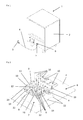
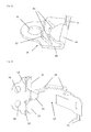
- FIG. 1 shows as an exemplary electrical device 1 a dishwasher with the possibility of device connection to the house electrical installation via the device connection system consisting of Schukostecker 3, device connection line 4, device connection box 5 and device connector 6.
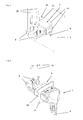
- the FIG. 2 shows a device connector 6 of a device connection system with integrated protective conductor connection for three-phase devices in the installed position on the housing insertion opening 7 of the housing 2 of the exemplary three-phase device in the direction of the outer wall of the inner region of the device 1 ago.
- the device connector 6 is formed trough-like and carries inside the conductor contacts 9, to which the current-carrying, not shown, power supply line is connected by means of plug contacts. These conductor contacts 9 are in operative connection with contacts to which the device internal wiring 16 is connected or connectable.
- the protective conductor contact 17 is arranged, which is operatively connected via the contact lug 11 with the power contact clamping spring 8.
- the trough of the device connector plug 6 has a top on the entire circumference projecting trough edge 20. In this trough edge 20 three side of the device connector plug 6 each two position guides 19 are formed.
- Power.klemmfeder 8 is arranged, which after the plane-parallel placement of the device plug 6 on the housing insertion opening 7 by means of guided through the position guides 19 sliding movement of the device connector 6 with its integrated power contact clamp spring 8 towards the edge of the housing insertion opening. 7 is mechanically and electrically operatively connected to the device housing.
- the power contact clamping spring 8 on the edge region of the housing insertion opening 7 secure the locking lugs 10 integrated on the opposite side of the device connection plug 6 and the trough edge 20 the position of the device connector plug 6 and the power contact terminal spring 8 and thus ensure a permanently secure connection of the Netzschleiter- and the device housing potential.
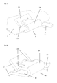
- FIG. 3 shows the device connection system with integrated protective conductor connection for three-phase devices consisting of separable device connector 6 and device connection box 5 with connected device connection cable 4, power contact clamp spring 8 and latching lugs 10 in mated and thus operatively connected state.
- FIG. 4 is a variant of in FIG. 3 device connection system with integrated protective conductor connection for three-phase devices described in which device connector 6 and device connection box 5 are designed as an inseparable functional unit, which are also referred to as a connection terminal. This is inserted from the outside into the outer wall of the device housing 2.
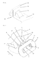
- FIG. 5 shows a device connector 6 of a device connection system with integrated protective conductor connection for connecting AC devices installed in the device housing 2 with connected device internal wiring 16 viewed from the inside of the device.
- the current-carrying connections are configured in a known manner.
- the device connector 6 consists of a parallelepiped, projecting into the interior of the device 1 part at the end of the conductor contacts 9 are mounted. At the other end of the device connector plug 6, a stop collar 21 is arranged.
- the Verrastnasen 10 are on the arranged externally on the device housing 2 stop collar 21, which secure the device connector 6 and arranged on the stop collar 21 towards the device interior power terminal clamp 8 in its installed position in the housing insertion opening 7, and thus a permanently secure operative connection of connected to the power contact clamp spring 8 network protection conductor with the device housing. 2 to ensure.
- housing insertion opening 7 of this When inserting the device connector plug 6 in the higher than the height of the device connector plug 6 formed housing insertion opening 7 of this is moved in the upper part of the housing insertion opening 7 to the abutment of the stop collar 21 on the outer wall of the device housing 2, so that arranged on the underside of the device connector plug 7 Power.klemmfeder 8 is positioned over the outer wall of the device. Thereafter, a “down” press the device connector plug 6, whereby this reaches the engagement position of the power contact clamp spring 8 on the edge of the housing insertion opening 7 of the device housing 2 and the locking latches 10 in the housing insertion opening 7.
- FIG. 6 shows a complete device connection system for AC in functional arrangement consisting of device connector 6 installed in the partially illustrated device housing 2 and the inserted device connection box 5 with the connected device connection cable 4 and the device internal wiring 16 from the insertion of the device connection box 5 in the device connector.
- FIGS. 7, 8 , and 14 show two variants of the formation of the power contact clamping spring 8, which can be used in the aforementioned embodiments.
- FIG. 7 shows the detailed view of an operatively connected to the housing 2 of the electrical device Powerquantklemmfeder 8.
- This power contact clamping spring 8 is integrally formed and U-shaped.
- the end of a leg of the power contact clamping spring 8 is designed by incisions so projecting from the device housing 2 that the front end of an insertion 12 and the opposite end forms a trigger guard claw 13.
- Both legs of the power contact clamping spring 8 comprise the device housing 2 by clamping and form the clamping spring 14.
- On the side of the power contact clamping spring 8, a contact terminal lug 11 is arranged.
- the over-bending of the power contact clamping spring 8 in the direction of the housing secured clamping and spring action of the contact system.
- the trigger guard claw 13 ensures that the power contact clamping spring 8 is self-secured against removal from the device housing. Tolerances or differences in the sheet thicknesses of the device housing 2 are compensated by the clamping spring 14. A relief in the installation of the scraper contact spring ensures the insertion bevel 12th
- FIG. 8 shows separately the in FIG. 7 shown power contact clamping spring 8.
- the particularly large contact surface 15 can be seen, especially in comparison to the conventional in the well-known prior art contacts.
- the contact force of the power contact clamping spring 8 can be controlled over a wide range in conjunction with the trigger guard claws 13.
- FIG. 9 shows a possible embodiment of the device connector plug 6 for device housing 2 with particularly high strength requirements and thus particularly minimalist housing insertion openings 7 in the installed position in the device housing 2 in a perspective view.
- FIG. 11 shows a further possible embodiment of the power contact clamping spring 8 in a perspective view of the device housing of the electrical equipment, in which the sheet metal cut must be performed minimalist for reasons of strength.
- This power contact clamping spring 8 is also formed in one piece and consists of a metal strip, one end of which has a U-shaped recess. This end is bent by two bends so that in cross-section, as it were, a triangle is formed, wherein the original end protrudes perpendicularly from the metal strip as a straight surface and forms the contact surface 15. Furthermore, in the metal strip almost underneath the contact surface 15, an element is unlatched as a trigger guard claw 13.
- the Kunststoffskralle 13 the Kunststoffskralle 13 can be set particularly high and at the same time greater thickness tolerances of the housing plates are compensated.
- FIG. 12 is a further embodiment of the device connector plug 6 in mounting position in front of the device housing 2 shown in a perspective view.
- the basic structure corresponds to the embodiment according to the FIGS. 5 and 6 ,
- the conductor contacts 9 and the protective conductor 17 are incorporated with the contact terminal lug 11 as a connecting element to the clamping spring 14.
- the housing insertion opening 7 is formed round, on the periphery of four in the wall of the device housing 2 outgoing Einzhouaussparungen 22 are arranged.
- retaining elements 23 are arranged with the Einwareaussparungen.
- a power contact clamping spring 8 is arranged instead of the holding element 23, which is also designed correspondingly with the Ein manufacturedaussparitch 22.
- FIG. 13 shows the in FIG. 12 shown device connector 6 in the installed position from the inside of the device out.
- the device plug 6 is shown in its Ein roomdposition in which the holding elements 23 and the power contact clamp spring 8 are latched behind the wall of the device housing 2 between the Ein Industriessparitch 22.
- FIG. 14 shows a special embodiment of the power contact clamping spring 8 without trigger guard claw 13, as shown in FIGS FIGS. 7 and 8 shown.
- the actual contact points between the clamping spring 14 and the wall of the device housing 2 are on the one hand in terms of area and on the other hand formed linear.
- This special embodiment is used in particular when the device housing 2 have special surfaces - eg galvanized, chrome-plated, etc. - and a violation of these could cause the risk of increased corrosion or impairment of the optics.
- FIG. 15 shows an enlarged detail view of a power contact clamp spring 8 with fixing hole 24 without housing.
- the fixing hole 24 may have a thread.
- the fixing hole may be formed as a slot.
- the fixing hole 24 serves as a connecting device.
- FIG. 16 shows a perspective detailed view of an alternative power contact clamping spring 8 with vibration-decoupled connection points with contact elements.
- the individual phases and the protective conductor can be attached by means of solder contact 26.
- solder contact 26 Alternatively, previously described contacting options are realized.
- the relief shaping 25 a vibration decoupling for mechanical vibrations is realized.
Landscapes
- Details Of Connecting Devices For Male And Female Coupling (AREA)
- Connector Housings Or Holding Contact Members (AREA)
Abstract
Description
- Die Erfindung betrifft einen Stecker und ein Geräteanschlusssystem mit integriertem Schutzleiteranschluss für elektrische Geräte, welches für unterschiedliche Versorgungsspannungen geeignet ist sowie ein Elektrogerät.
- Elektrische Geräte wie Elektrokochherde, Backröhren, Kühlschränke, Mikrowellen, Geschirrspüler, Bearbeitungsmaschinen in der industriellen Fertigung, Fahrzeugdiagnosegeräte usw. benötigen für ihre Funktion elektrische Energie.
- Zur Gewährleistung der Energieversorgung verfügen die meisten dieser und ähnliche Geräte über ein Geräteanschlusssystem als Übergabestelle der Elektroenergie zwischen der elektrischen Zuleitung und der Geräteinnenverdrahtung.
- Insbesondere bei Geräten mit einer Betriebsspannung über 250 V werden diese auch als Anschlussterminal bezeichnet.
- Dies ist aus folgenden unterschiedlichen Gründen erforderlich, wie:
- die elektrische Geräteanschlussleitung soll austauschbar sein,
- das Gerät soll erst am Ende des Fertigungsdurchlaufes durch eine länderspezifische Geräteanschlussleitung komplettiert werden
- die Geräteanschlussleitung unterliegt einer erhöhten mechanischen und/oder chemischen Belastung und muss daher beständiger sein als die Geräteinnenverdrahtung und
- die Geräteinnenverdrahtung unterliegt erhöhten thermischen Belastungen und muss daher thermisch beständigeres Isolationsmaterial als die Geräteanschlussleitung besitzen.
- Die Geräteanschlusssysteme werden in der industriellen Fertigung dieser Geräte durch den Gerätehersteller innerhalb des Fertigungsprozesses in die Geräteaußenwand montiert. In einem weiteren Fertigungsschritt muss die Netzleitung über die Verbindungsstellen mit der Geräteinnenverdrahtung verbunden werden. Je nach zum Einsatz kommendem System kann dies mittels verschiedener Technologien erfolgen, wie z.B. Verbindung der Adern der Geräteanschlussleitung und der Geräteinnenverdrahtung mittels lösbarer Verbindungstechnologien - Schraubklemmen, Steckkontakte, Federzugklemmen, Schneidklemmen usw., oder/und mittels unlösbarer Verbindungstechnologien, wie thermisches Schweißen, Ultraschallschweißen, Löten, Crimpen, und dergleichen.
- Unabhängig davon welche der benannten Verbindungstechnologien zwischen den Adern der Geräteanschlussleitung und der Geräteinnenverdrahtung zum Einsatz kommt, sind zu deren Realisierung meist zwei Realisierungsschritte notwendig:
- 1. Montage des Geräteanschlusssysteme in die Einbringöffnung der Gerätewand.
- 2. Verbindung der entsprechenden Anzahl an Adern der Zuleitung mit einer korrespondierenden Anzahl an Geräteinnenverdrahtungsleitungen - z.B.: bei einem Elektrogerät für Wechselstrom und Verwendung einer Schutzmaßnahme gegen gefährliche Körperströme, auf der Basis eines Schutzleiteranschlusses sind dies drei elektrische Verbindungen. Bei einem Elektrogerät für Drehstrom und gleicher Schutzmaßnahme gegen gefährliche Körperströme sind dies fünf elektrische Verbindungen.
- Besteht das Gerätegehäuse aus einem elektrisch leitfähigem Material, welches im Fehlerfalle, z.B. Körperschluss, eine gefährliches Potential annehmen kann, und wird der Schutz gegen gefährliche Körperströme durch Anwendung einer Schutzmaßnahme mit Schutzleiteranschluss sichergestellt, muss auf der Geräteinnenverdrahtungsseite eine sichere, niederimpedante Verbindung des Schutzleiters mit dem Gerätegehäuse sichergestellt werden.
- Nach dem Stand der Technik sind der Einbau des Geräteanschlusssysteme in das Gerätegehäuse und die Verbindung des Schutzleiters der Geräteanschlussleitung mit dem leitfähigen Gerätegehäuse zwei getrennte technologische Schritte, welche zusätzliche Montagezeiten und zusätzliches Verbindungsmaterial bedingen.
- In den Druckschriften
DE 10 2005 029 384 A1 ,DE 10 2008 009 142 A1 ,DE 10 2007 057 335 A1 undDE 10 2005 040 241 A1 werden modulare Anschlusssysteme zur Herstellung der elektrischen Verbindung zwischen der Gebäudeelektroinstallation und der Geräteinnenverdrahtung eines elektrischen Gerätes beschrieben. - Die in den Druckschriften dargestellten Vorteile der beschriebenen Geräteanschlusssysteme bedingen jedoch bei den Herstellern der elektrischen Geräte einen erheblich höheren Fertigungs- und Materialaufwand und verursachen dadurch höhere Kosten.
- So eignen sich die in den Druckschrift
DE 10 2007 057 335 A1 undDE 10 2005 040 241 A1 beschriebene Lösung nur für eine Kontaktierung der Geräteanschlussleitung auf eine Innengeräteverdrahtung in Form einer gedruckte Schaltung, wie elektronische Leiterplatte, da durch diese ein Verschieben der Steckerkontakte beim Stecken der Dose vermieden wird. - Unabhängig davon muss in einem zusätzlichen technologischen Schritt und unter Einsatz von zusätzlichem Material die Verbindung des Schutzleiters mit dem Gerätegehäuse realisiert werden.
- Die in den Druckschriften
DE 10 2005 029 384 A1 undDE 10 2008 009 142 A1 beschriebenen Lösungen sind aufgrund ihrer Bauform stark auf spezielle Anwendungen begrenzt. Auch sie bedingen die vorab beschriebenen zusätzlichen technologischen Schritte und zusätzlichen Materialien für einen Anschluss des Schutzleiters an das Gerätegehäuse. - Nach
DE 20 2013 101 698 ist ein Schutzleiterkontaktiersystem für Geräteanschlusssysteme elektrischer Geräte bekannt, die für unterschiedliche Versorgungsspannungen geeignet sind. Bei dieser Lösung ist eine Schutzleiteranschlusslasche Bestandteil des Gerätegehäuses. Die Schutzleiteranschlusslasche ist an einer Einbringöffnung für das Geräteanschlusssystem ausgebildet und mit einem korrespondierend ausgebildeten Schutzleiteranschlusskontakt eines Geräteanschlusssystems wirkverbindbar. - Da der Kosten- und Qualitätsdruck innerhalb der industriellen Fertigung weiter steigt, ist es für jeden Hersteller existentiell wichtig, alle möglichen Kostenreduktionspotentiale zu erschließen, ohne Abstriche bei der Qualität zu verursachen.
- Es ist also die Aufgabe der vorliegenden Erfindung, ein in Herstellung und Montage besonders kostengünstiges System zur direkten Verbindung des Schutzleiters der Geräteanschlussleitung mit dem Gerätegehäuse und/oder der Geräteinnenverdrahtung vorzuschlagen.
- Dieses System soll die elektrische Funktions- und Gerätesicherheit dauerhaft gewährleisten und gleichzeitig für den Anwender der vorliegenden Erfindung ein wesentliches Einsparungspotential an Montagezeit und Montagematerial erschließen.
- Durch die vorgeschlagene Lösung sollen Probleme bisheriger Lösungsansätze bei der Kontaktierung auf die Gerätegehäuse, wie:
- Toleranzen bei der Materialstärke der Gehäusebleche
- Blechbeschichtungen bzw. Blechverunreinigungen
- Zu geringe Kontaktanpresskraft und zu geringe Kontakt fläche
- Die Lösung soll in entsprechenden Varianten sowohl für Geräte mit einem Dreh- oder Wechselstromanschluss nutzbar sein.
- Diese Aufgabe wird durch einen Stecker mit den Merkmalen des Patentanspruchs 1 und ein Geräteanschlusssystem mit integriertem Schutzleiteranschluss für elektrische Geräte mit den Merkmalen des Patentanspruchs 9 sowie ein Elektrogerät gemäß Anspruch 21 gelöst. Vorteilhafte Ausgestaltungen ergeben sich aus den jeweiligen abhängigen Ansprüchen.
- Durch Anwendung von Montagezeit- und Montagematerial sparender Verbindungstechnologie, wird bereits bei der Montage des Geräteanschlusssystems in die Einbringöffnung des Gerätegehäuses des mit Elektroenergie zu versorgenden Gerätes die niederimpedante, mechanisch sichere Verbindung des Schutzleiterpotentials des Energieversorgungsnetzes und dem Gehäusepotential des Gerätes hergestellt. Dadurch ist eine wesentliche Grundvoraussetzung für die sichere Funktion der Schutzmaßnahmen gegen gefährliche Körperströme bereits durch den Einbau des Geräteanschlusssystems herstellt.
- Die Lösung dieser Aufgabe durch die Erfindung ist auch gekennzeichnet durch ein Geräteanschlusssystem mit integriertem Schutzleiteranschluss, welches an den Außenbegrenzungsflächen oder im Inneren des elektrischen Gerätes angebracht ist.
- Das Geräteanschlusssystem mit integriertem Schutzleiteranschluss weist je nach netzseitigem Strom- bzw. Spannungsversorgungssystem die für die Gerätefunktion erforderliche Anzahl an Verbindungsstellen - Schraubkontaktstellen, Schweißstellen, Federzugklemmstellen, Schneidkontaktklemmstellen, Klemmkontaktstellen, usw. - zwischen der Geräteanschlussleitung und der Geräteinnenverdrahtung auf.
- Zusätzlich können, bei Bedarf, diese Verbindungsstellen mit Kontaktelementen zur Realisierung von Verbindungen zwischen den Leitern - z.B. Phase L1 und Phase L2, so genannte Brücken - ausgeführt sein.
- Vor allem weist das Geräteanschlusssystem mit integriertem Schutzleiteranschluss eine geeignete Kontaktierung des Netzleitungsschutzleiters direkt mit dem Gerätegehäuse in der Art auf, dass die Kontaktierung unmittelbar bei der Montage und nicht durch einen zusätzlichen Arbeitsschritt und unter Verwendung von zusätzlichem Verbindungsmaterial erfolgt.
- Durch diese technische Umsetzung wird gewährleistet, dass bereits beim Einfügen des Geräteanschlusssystem mit integriertem Schutzleiteranschluss in das Gerätegehäuse eine mechanisch sowie elektrisch sichere und dauerhafte Verbindung des Schutzleiter- mit dem Gerätegehäusepotentials erfolgt, und damit die Voraussetzung für den Schutz gegen gefährliche Körperströme dauerhaft sichergestellt wird.
- Zum Erreichen dieses Zieles muss der Gehäuseausschnitt des elektrischen Gerätes, in welchen das Geräteanschlusssystem eingefügt wird, nicht extra um eine Schutzleiteranschlusslasche oder ähnliche Verbindungselemente erweitert werden.
- Es ist ausreichend, dass mindestens ein Bestandteil des Geräteanschlusssystems mit integriertem Schutzleiteranschluss über die neuartige Powerkontaktklemmfeder verfügt, welche in geeigneter Form mit dem Schutzleiter der Geräteanschlussleitung elektrisch wirkverbunden ist. Die Powerkontaktklemmfeder ist gekennzeichnet durch hohe Verbindungskräfte und große Verbindungsflächen zur Gehäusewand um somit einen geringen Übergangswiderstand zwischen Netzschutzleiter und Gehäusewand dauerhaft sicherzustellen.
- Bei der Montage und nach dem Erreichen der Montageendposition des Geräteanschlusssystems mit integriertem Schutzleiteranschluss im Gerätegehäuse gewährleisten geeignete Konstruktionselemente zur Lagebestimmung und Lagesicherung, dass die Schutzleiterpotentialverbindung zwischen Stromversorgungsnetz und Gerätegehäuse sicher erreicht und dauerhaft gesichert ist.
- Bei Geräteanschlusssystemen mit integriertem Schutzleiteranschluss mit untrennbaren Verbindungen zwischen Geräteanschlussleitungen und Geräteinnenverdrahtung wird durch geeignete konstruktive Maßnahmen - z.B. Rastnasen - dauerhaft sichergestellt, dass das Terminal und damit die Schutzleiterverbindung nicht vom Gerät getrennt werden kann.
- Bei Geräteanschlusssystem mit integriertem Schutzleiteranschluss mit einer trennbaren Verbindungen zwischen Geräteanschlussleitungen und Geräteinnenverdrahtung ist durch die verlängerte Ausführung und/oder die in Richtung Netzanschluss verschobene Lage des Schutzleitersteckkontaktes sichergestellt, dass beim Ziehen der Dose aus dem Stecker, immer erst die stromführenden Kontakte und erst dann der Schutzleiter getrennt wird. Diese Maßnahme erhöht die Gerätesicherheit wesentlich.
- Durch die konstruktiven Besonderheiten, bei gleichzeitiger Vereinfachung des Gesamtsystems, weist die Erfindung eine Vielzahl von Vorteilen auf:
- > Sicher und langlebige Verbindung zwischen Netzschutzleiter- und Gehäusepotential auch bei unterschiedlichen Blechstärken und unterschiedlichen Blechbeschichtungen
- > Vereinfachung der Blechausstanzung
- > Verringerung von Material- und Fertigungsaufwendungen für das Geräteanschlusssystem mit integriertem Schutzleiteranschluss
- > Möglichkeit einer festen und einer lösbaren Verbindung zwischen Geräteanschlussleitung und Geräteinnenverdrahtung
- > Einsparung von Fertigungszeit durch gleichzeitiges Einfügen des Geräteanschlusssystems mit integriertem Schutzleiteranschluss in und elektrisches Verbinden des Schutzleiters mit dem Gerätegehäuse
- > Einsparung von zusätzlichen Materialien für die Verbindung des Netzschutzleiters mit dem Geräteschutzleiter bzw. dem Gerätegehäuse
- > Möglichkeit einer vollautomatischen Fertigung und Geräteprüfung
- > Vereinfachung des Geräteanschlusses an die Gebäudeelektroinstallation.
- Folgende Ausführungsformen sind mit umfasst.
- Ein zuvor beschriebenes Geräteanschlusssystem mit integriertem Schutzleiteranschluss, wobei alternativ oder kumulativ das Geräteanschlusssystem muldenartig ausgebildet ist und die Mulde am oberen Ende des gesamten Umfangs einen abstehenden Muldenrand (20) aufweist, in dem mehrseitig und an jeder dieser Seite mindestens eine Positionsführung (19) ausgebildet ist und im äußeren Bereich der Mulde des Geräteanschlusssystems die vom Muldenrand (20) abragende Powerkontaktklemmfeder (8) angeordnet ist.
- Ein zuvor beschriebenes Geräteanschlusssystem mit integriertem Schutzleiteranschluss, wobei alternativ oder kumulativ ein in das Geräteinnere des Gerätes (1) ragender Teil des Geräteanschlusssystems quaderähnlich ausgebildet und an dem außen auf dem Gerätegehäuse (2) anliegenden Ende des Geräteanschlusssystems ein Anschlagbund (21) angeordnet ist, an dem innenseitig, in Richtung Geräteinneres des Gerätegehäuses (2) die Powerkontaktklemmfeder (8) angeordnet ist, die mit dem Gerätegehäuse (2) mechanisch und elektrisch wirkverbunden ist.
- Ein zuvor beschriebenes Geräteanschlusssystem mit integriertem Schutzleiteranschluss, wobei alternativ oder kumulativ ein in das Geräteinnere des Gerätes (1) ragender Teil des Geräteanschlusssystems quaderähnlich ausgebildet und an dem außen auf dem Gerätegehäuse (2) anliegenden Ende des Geräteanschlusssystems ein Anschlagbund (21) angeordnet ist, an dem innenseitig, in Richtung Geräteinneres des Gerätegehäuses (2) Verrastnasen (10) angeordnet sind, die mit dem Gerätegehäuse (2) wirkverbunden sind.
- Ein zuvor beschriebenes Geräteanschlusssystem mit integriertem Schutzleiteranschluss, wobei alternativ oder kumulativ die Gehäuseeinbringöffnung (7) rund ausgebildet ist, auf deren Umfang mindestens zwei in die Wand des Gerätegehäuses (2) abgehende Einführaussparungen (22) angeordnet sind und ein in das Geräteinnere des Gerätes (1) ragender Teil des Geräteanschlusssystems korrespondierend ausgebildet ist, an der der Gehäuseeinbringöffnung (7) zugewandten Seite des Geräteanschlusssystems mindestens ein mit einer Einführaussparung (22) korrespondierend ausgebildetes Halteelemente (23) und die ebenfalls mit den Einführaussparungen (22) korrespondierend gestaltete Powerkontaktklemmfeder (8) mit integrierter Klemmfeder (14) angeordnet sind.
- Ein zuvor beschriebenes Geräteanschlusssystem mit integriertem Schutzleiteranschluss, wobei alternativ oder kumulativ die Gehäuseeinbringöffnung (7) derart geometrisch beliebig ausgebildet ist, insbesondere quadratisch oder elliptisch, dass am Umfang der Gehäuseeinbringöffnung (7) mindestens zwei in die Wand des Gerätegehäuses (2) abgehende Einführaussparungen (22) angeordnet oder ausgebildet sind, und ein in das Geräteinnere des Gerätes (1) ragender Teil der Powerkontaktklemmfeder (8) so korrespondierend ausgebildet ist, dass nach dem Einsetzen des Geräteanschlusssystems in die Gehäuseeinbringöffnung (7) ein Verdrehen des Geräteanschlusssystems in eine Verrastposition möglich ist.
- Ein zuvor beschriebenes Geräteanschlusssystem mit integriertem Schutzleiteranschluss, wobei alternativ oder kumulativ die Powerkontaktklemmfeder (8) ohne Abzugsschutzkralle (13) ausgebildet ist und die Kontaktstellen zwischen Klemmfeder (14) und der Wand des Gerätegehäuses (2) einerseits flächenmäßig und andererseits quasi linienförmig ausgebildet sind.
- Im Folgenden wird die Erfindung anhand von mehreren Ausführungsbeispielen mit den
Figuren 1 bis 14 näher erläutert. Es zeigen - Fig. 1
- ein elektrisches Gerät - Geschirrspüler 1 anschließbar über eine Geräteanschlussleitung 4 mit Schukostecker 3,
- Fig. 2
- einen Geräteanschlussstecker 6 für Drehstromsysteme in Einbauposition über der Gehäuseeinbringöffnung 7 des Gerätegehäuses 2,
- Fig. 3
- einen komplettes Geräteanschlusssystem mit integriertem Schutzleiteranschluss für Drehstromgeräte bestehend aus zwei voneinander trennbaren Einheiten, dem Geräteanschlussstecker 6 mit Powerkontaktklemmfeder 8 verbunden mit der Geräteanschlussdose 5 und der Geräteanschlussleitung 4,
- Fig. 4
- eine Variante des in
Figur 3 . gezeigten, trennbaren Geräteanschlusssystem mit integriertem Schutzleiteranschluss für Drehstromgeräte als untrennbare Ausführungsform, - Fig. 5
- einen Geräteanschlussstecker 6 zum Anschluss von Wechselstromgeräten eingebaut im Gehäuse 2 mit angeschlossener Geräteinnenverdrahtung 16 mit dem Gehäuserand der Einbringöffnung 7 wirkverbundenen und mit den Verrastnasen 10 gesicherten Powerkontaktklemmfeder 8,
- Fig. 6
- ein komplettes Geräteanschlusssystem mit integriertem Schutzleiteranschluss für Wechselstrom bestehend aus Geräteanschlussstecker 6 eingebaut im Gehäuse 2 und der eingesteckten Geräteanschlussdose 5 mit der angeschlossenen Geräteanschlussleitung 4 und der Geräteinnenverdrahtung 16,
- Fig. 7
- die Detailansicht einer mit dem Gehäuse 2 des elektrischen Gerätes wirkverbundenen Powerkontaktklemmfeder 8,
- Fig. 8
- die vergrößerte Detailansicht einer Powerkontaktklemmfeder 8 ohne Gehäuse,
- Fig. 9
- eine mögliche Ausgestaltungsform des Geräteanschlusssteckers 6 für Gerätegehäuse 2 mit besonders hohen Festigkeitsanforderungen und damit besonders minimalistischen Gehäuseeinbringöffnungen 7 in Einbauposition im Gerätegehäuse 2 in perspektivischer Darstellung,
- Fig. 10
- die Detailansicht einer Variante der Powerkontaktklemmfeder 8 in Seitenansicht mit Gehäuse 2,
- Fig. 11
- die perspektivische Darstellung der in
Figur 10 in Seitenansicht gezeigten Powerkontaktklemmfeder 8, - Fig. 12
- die mögliche Ausgestaltungsform des Geräteanschlusssteckers 6 in Montageposition vor dem Gerätegehäuse 2 in perspektivischer Darstellung,
- Fig. 13
- die in
Figur 12 dargestellten Geräteanschlussstecker 6 in Einbauposition aus dem Geräteinneren heraus, - Fig. 14
- die perspektivische Darstellung einer Powerkontaktklemmfeder 8 ohne Abzugsschutzkralle (13),
- Fig. 15
- eine vergrößerte Detailansicht einer Powerkontaktklemmfeder 8 mit Fixierloch ohne Gehäuse und
- Fig. 16
- eine perspektivische Detailansicht einer alternativen Powerkontaktklemmfeder 8 mit schwingungsentkoppelten Verbindungsstellen für Kontaktelementen (Phasen und Schutzleiter).
- Die Darstellung der Ausführungsbeispiele geht von dem Grundgedanke der Lösung aus, dass die elektrische und mechanische Wirkverbindung des Netzschutzleiters mit dem Gerätegehäuse 2 über die Powerkontaktklemmfeder 8 bereits bei der Montage des Geräteanschlusssystem mit integriertem Schutzleiteranschluss in das Gehäuse des elektrischen Gerätes sicher und dauerhaft hergestellt wird.
- Bei Ausführungsformen, welche eine zerstörungsfreie Trennung der Adern der Geräteanschlussleitung 4 von den Adern der Geräteinnenverdrahtung 16 erlauben -
Figuren 2 ,3 ,5, 6 ,9 ,12 und13 - ist der Schutzleiterkontakt 17 in seiner Länge und/oder in seiner geometrischen Position so ausgebildet, dass die stromführenden Leiterkontakte 9 beim Trennen der Geräteanschlussdose 5 vom Geräteanschlussstecker 6 vor dem Schutzleiterkontakt 17 getrennt werden. Diese Maßnahme erhöht die Gerätesicherheit wesentlich. - Bei Geräteanschlusssystem mit integriertem Schutzleiteranschluss mit untrennbaren Verbindungen zwischen Geräteanschlussleitungen und Geräteinnenverdrahtung -
Figuren 4 - wird durch geeignete konstruktive Maßnahmen - z.B. Rastnasen - dauerhaft sichergestellt, dass das Geräteanschlusssystem und damit die Schutzleiterverbindung nicht vom Gerät getrennt werden kann. - Die
Figur 1 zeigt als exemplarisches elektrisches Gerät 1 einen Geschirrspüler mit der Möglichkeit des Geräteanschlusses an die Hauselektroinstallation über das Geräteanschlusssystem bestehend aus Schukostecker 3, Geräteanschlussleitung 4, Geräteanschlussdose 5 und Geräteanschlussstecker 6. - Die
Figur 2 zeigt einen Geräteanschlussstecker 6 eines Geräteanschlusssystems mit integriertem Schutzleiteranschluss für Drehstromgeräte in Einbauposition über der Gehäuseeinbringöffnung 7 des Gehäuses 2 des exemplarischen Drehstromgerätes in Richtung Außenwand vom inneren Bereich des Gerätes 1 her. Der Geräteanschlussstecker 6 ist muldenartig ausgebildet und trägt im Inneren die Leiterkontakte 9, an die die stromführende, nicht dargestellte Netzzuleitung mittels Steckkontakten angeschlossen wird. Diese Leiterkontakte 9 stehen in Wirkverbindung mit Kontakten, an die die Geräteinnenverdrahtung 16 angeschlossen bzw. anschließbar ist. Im Muldeninneren ist auch der Schutzleiterkontakt 17 angeordnet, der über die Kontaktfahne 11 mit der Powerkontaktklemmfeder 8 wirkverbunden ist. Die Mulde des Geräteanschlusssteckers 6 weist oben einen am gesamten Umfang abstehenden Muldenrand 20 auf. In diesem Muldenrand 20 sind dreiseitig des Geräteanschlusssteckers 6 jeweils zwei Positionsführungen 19 ausgebildet. - Im äußeren Frontbereich des Geräteanschlusssteckers 6 ist eine vom Muldenrand 20 abragende Powerkontaktklemmfeder 8 angeordnet, welche nach dem planparallelem Aufsetzen des Gerätesteckers 6 auf die Gehäuseeinbringöffnung 7 mittels einer durch die Positionsführungen 19 geführt Schiebebewegung des Gerätesteckers 6 mit seiner integrierter Powerkontaktklemmfeder 8 in Richtung Rand der Gehäuseeinbringöffnung 7 mit dem Gerätegehäuse mechanisch und elektrisch wirkverbunden wird. Zum Abschluss der Schiebebewegung der Powerkontaktklemmfeder 8 auf dem Randbereich der Gehäuseeinbringöffnung 7 sichern die an der gegenüberliegenden Seite des Geräteanschlusssteckers 6 und im Muldenrand 20 integrierten Verrastnasen 10 die Lageposition des Geräteanschlusssteckers 6 und der Powerkontaktklemmfeder 8 und gewährleisten somit eine dauerhaft sichere Verbindung des Netzschutzleiter- und des Gerätegehäusepotentials.
- Die
Figur 3 zeigt das Geräteanschlusssystem mit integriertem Schutzleiteranschluss für Drehstromgeräte bestehend aus voneinander trennbarem Geräteanschlussstecker 6 und Geräteanschlussdose 5 mit angeschlossener Geräteanschlussleitung 4, Powerkontaktklemmfeder 8 und Verrastnasen 10 in zusammengestecktem und damit wirkverbundenen Zustand. - In der
Fig. 4 ist eine Variante des inFigur 3 beschriebenen Geräteanschlusssystems mit integriertem Schutzleiteranschluss für Drehstromgeräte dargestellt, bei welcher Geräteanschlussstecker 6 und Geräteanschlussdose 5 als untrennbare Funktionseinheit ausgeführt sind, welche auch als Anschlussterminal bezeichnet werden. Diese wird von außen in die Außenwand des Gerätegehäuses 2 eingesetzt. - Die
Figur 5 zeigt einen Geräteanschlussstecker 6 eines Geräteanschlusssystems mit integriertem Schutzleiteranschluss zum Anschluss von Wechselstromgeräten eingebaut im Gerätegehäuse 2 mit angeschlossener Geräteinnenverdrahtung 16 aus dem Geräteinnenraum heraus betrachtet. Die stromführenden Anschlüsse sind in bekannter Weise ausgestaltet. - Der Geräteanschlussstecker 6 besteht aus einem quaderähnlichen, in das Innere des Gerätes 1 ragenden Teil, an dessen Ende die Leiterkontakte 9 angebracht sind. Am anderen Ende des Geräteanschlusssteckers 6 ist ein Anschlagbund 21 angeordnet. Die Verrastnasen 10 sind an dem außen am Gerätegehäuse 2 anliegendem Anschlagbund 21 angeordnet, welchen den Geräteanschlussstecker 6 und die am Anschlagbund 21 in Richtung Geräteinneren angeordnete Powerkontaktklemmfeder 8 in ihrer Einbaulage in der Gehäuseeinbringöffnung 7 sichern, und damit eine dauerhaft sichere Wirkverbindung des an die Powerkontaktklemmfeder 8 angeschlossenen Netzschutzleiters mit dem Gerätegehäuse 2 sicherstellen. Beim Einschieben des Geräteanschlusssteckers 6 in die höher als die Höhe des Geräteanschlusssteckers 6 ausgebildete Gehäuseeinbringöffnung 7 wird dieser im oberen Bereich der Gehäuseeinbringöffnung 7 bis zum Anliegen des Anschlagbundes 21 an der Außenwand des Gerätegehäuses 2 bewegt, so dass die an der Unterseite des Geräteanschlusssteckers 7 angeordnete Powerkontaktklemmfeder 8 über der Außenwand des Gerätes positioniert ist. Danach erfolgt ein nach "unten" drücken des Geräteanschlusssteckers 6, wodurch dieser mit Einrasten der Powerkontaktklemmfeder 8 auf dem Rand der Gehäuseeinbringöffnung 7 des Gerätegehäuses 2 und dem Verrasten der Verrastnasen 10 in der Gehäuseeinbringöffnung 7 die Endposition erreicht.
- Die
Figur 6 zeigt ein komplettes Geräteanschlusssystem für Wechselstrom in Funktionsanordnung, bestehend aus Geräteanschlussstecker 6 eingebaut in das ausschnittweise dargestellte Gerätegehäuse 2 und der eingesteckten Geräteanschlussdose 5 mit der angeschlossenen Geräteanschlussleitung 4 und der Geräteinnenverdrahtung 16 aus der Einsteckrichtung der Geräteanschlussdose 5 in den Geräteanschlussstecker 6. - Die
Figuren 7, 8 , und14 zeigen zwei Varianten der Ausbildung von der Powerkontaktklemmfeder 8, die bei den vorgenannten Ausführungsbeispielen einsetzbar sind. - Die
Figur 7 zeigt die Detailansicht einer mit dem Gehäuse 2 des elektrischen Gerätes wirkverbundenen Powerkontaktklemmfeder 8. Diese Powerkontaktklemmfeder 8 ist einstückig und U-förmig ausgebildet. Das Ende eines Schenkels der Powerkontaktklemmfeder 8 ist durch Einschnitte so abragend vom Gerätegehäuse 2 ausgeführt, dass das vordere Ende eine Einführschräge 12 und das entgegengesetzte Ende eine Abzugsschutzkralle 13 bildet. Beide Schenkel der Powerkontaktklemmfeder 8 umfassen das Gerätegehäuse 2 klemmend und bilden die Klemmfeder 14. An der Seite der Powerkontaktklemmfeder 8 ist eine Kontaktanschlussfahne 11 angeordnet. Zu erkennen ist die durch Überbiegung der Powerkontaktklemmfeder 8 in Richtung Gehäuse sichergestellte Klemm- und Federwirkung des Kontaktsystems. Die Abzugsschutzkralle 13 stellt sicher, dass die Powerkontaktklemmfeder 8 gegen Abziehen vom Gerätegehäuse selbstgesichert ist. Toleranzen bzw. Unterschiede in den Blechstärken der Gerätegehäuse 2 werden ausgeglichen durch die Klemmfeder 14. Eine Erleichterung beim der Montage der Kratzkontaktfeder gewährleistet die Einführschräge 12. - Die
Figur 8 zeigt separat die inFigur 7 dargestellte Powerkontaktklemmfeder 8. Hier ist die besonders große Kontaktfläche 15 ersichtlich, insbesondere im Vergleich zu den im allgemein bekannten Stand der Technik gebräuchlichen Kontakten. Durch Material und geometrische Ausprägung der Klemmfeder 14 ist im Zusammenspiel mit den Abzugsschutzkrallen 13 die Anpresskraft der Powerkontaktklemmfeder 8 über weite Bereiche steuerbar. - Die
Figur 9 zeigt eine mögliche Ausgestaltungsform des Geräteanschlusssteckers 6 für Gerätegehäuse 2 mit besonders hohen Festigkeitsanforderungen und damit besonders minimalistischen Gehäuseeinbringöffnungen 7 in Einbauposition im Gerätegehäuse 2 in perspektivischer Darstellung. - Besonders gut zu sehen ist das mechanische Zusammenspiel zwischen der Klemmfeder 14 der Powerkontaktklemmfeder 8 und ihrer Abzugsschutzkralle 13 zur Einstellung optimaler Kontaktandruckkräfte zwischen ihren Kontaktflächen 15 und dem Gerätegehäuse 2 und der damit erreichten Minimierung der Übergangswiderstände zwischen Gehäuse 2 und Netzschutzleiter.
- In den
Figuren 10 und11 ist die mögliche Ausgestaltungsform der Powerkontaktklemmfeder 8 wirkverbunden mit dem Gerätegehäuse 2 für besondere Gehäuseanforderungen wie inFigur 9 beschrieben gezeigt. Das Zusammenspiel zwischen Klemmfeder 14 und Abzugsschutzkralle 13 zum Ausgleich von Toleranzen der Bleche des Gerätegehäuses 2 ist hier dargestellt. - Die
Figur 11 zeigt eine weitere mögliche Ausgestaltungsform der Powerkontaktklemmfeder 8 in perspektivischer Darstellung für Gerätegehäuse der elektrischen Geräte, bei welchen der Blechausschnitt aus Festigkeitsgründen minimalistisch ausgeführt werden muss. Diese Powerkontaktklemmfeder 8 ist ebenfalls einstückig ausgebildet und besteht aus einem Metallstreifen, dessen eines Ende eine U-förmige Aussparung aufweist. Dieses Ende ist durch zwei Abwinklungen so gebogen, dass im Querschnitt quasi ein Dreieck entsteht, wobei das ursprüngliche Ende als gerade Fläche senkrecht von dem Metallstreifen abragt und die Kontaktfläche 15 bildet. Weiterhin ist im Metallstreifen nahezu unterhalb der Kontaktfläche 15 ein Element als Abzugsschutzkralle 13 ausgeklinkt. Durch die gegensinnig gebogene Klemmfeder 14 und Abzugskralle 13 können die Kontaktanpresskräfte besonders hoch eingestellt und gleichzeitig größere Dicke-Toleranzen der Gehäusebleche ausgeglichen werden. - In
Figur 12 ist eine weitere Ausgestaltungsform des Geräteanschlusssteckers 6 in Montageposition vor dem Gerätegehäuse 2 in perspektivischer Darstellung gezeigt. Der grundsätzliche Aufbau entspricht der Ausführungsform nach denFiguren 5 und 6 . Im Geräteanschlussstecker 6 sind die Leiterkontakte 9 und der Schutzleiterkontakt 17 mit der Kontaktanschlussfahne 11 als Verbindungselement zur Klemmfeder 14 eingearbeitet. - Allerdings ist bei dieser Ausführungsform die Gehäuseeinbringöffnung 7 rund ausgebildet, auf deren Umfang vier in die Wand des Gerätegehäuses 2 abgehende Einführaussparungen 22 angeordnet sind. An der der Gehäuseeinbringöffnung 7 zugewandten Seite des Geräteanschlusssteckers 6 sind mit den Einführaussparungen 22 korrespondierend ausgebildete Halteelemente 23 angeordnet. An einer Stelle von den vier Halteelementen 23 ist anstelle des Halteelementes 23 eine Powerkontaktklemmfeder 8 angeordnet, die ebenfalls mit den Einführaussparungen 22 korrespondierend gestaltet ist.
- Durch Einstecken des Geräteanschlusssteckers 6 in die Gehäuseeinbringöffnung 7 in Einsetzrichtung gemäß Pfeil X werden die als Art Verrastnasen ausgebildeten Halteelemente 23 und die Powerkontaktklemmfeder 8, die nach den
Figuren 7, 8 , und14 ausgeführt sein kann, durch die Geräteeinbringöffnung 7 geschoben. Dadurch hat der Geräteanschlussstecker 6 seine Drehposition erreicht. Anschließend wird der Geräteanschlussstecker 6 durch eine im Ausführungsbeispiel Drehung in Uhrzeigerrichtung in seine Einbauendposition gebracht. - Die
Figur 13 zeigt den inFigur 12 dargestellten Geräteanschlussstecker 6 in Einbauposition aus dem Geräteinneren heraus. Der Geräteeinbaustecker 6 ist in seiner Einbauendposition dargestellt, in der die Halteelemente 23 und die Powerkontaktklemmfeder 8 hinter der Wand des Gerätegehäuses 2 zwischen den Einführaussparungen 22 verrastet sind. - Die
Figur 14 zeigt eine spezielle Ausführungsform der Powerkontaktklemmfeder 8 ohne Abzugsschutzkralle 13, wie in denFiguren 7 und 8 dargestellt. Die eigentlichen Kontaktstellen zwischen Klemmfeder 14 und der Wand des Gerätegehäuses 2 sind einerseits flächenmäßig und andererseits linienförmig ausgebildet. Diese spezielle Ausführungsform kommt insbesondere dann zum Einsatz, wenn die Gerätegehäuse 2 über spezielle Oberflächen - z.B. verzinkt, verchromt, usw. - verfügen und eine Verletzung dieser die Gefahr einer erhöhten Korrosion bzw. eine Beeinträchtigungen der Optik verursachen könnte. - Die
Figur 15 zeigt eine vergrößerte Detailansicht einer Powerkontaktklemmfeder 8 mit Fixierloch 24 ohne Gehäuse. Mittels des Fixierlochs 24 kann eine zusätzliche mechanische Verbindung mit dem Gehäuse realisiert werden. Zudem kann dabei auch die elektrische Leitfähigkeit verbessert werden. Das Fixierloch 24 kann ein Gewinde aufweisen. Zudem kann das Fixierloch als Langloch ausgebildet sein. Allgemein dient das Fixierloch 24 als Verbindungseinrichtung. - Die
Figur 16 zeigt eine perspektivische Detailansicht einer alternativen Powerkontaktklemmfeder 8 mit schwingungsentkoppelten Verbindungsstellen mit Kontaktelementen. An diese Verbindungsstellen können die einzelnen Phasen und der Schutzleiter mittels Lötkontakt 26 angebracht werden. Alternativ sind zuvor beschriebene Kontaktierungsmöglichkeiten realisiert. Insbesondere durch die Entlastungsausformung 25 ist eine Schwingungsentkopplung für mechanische Schwingungen realisiert. -
- 1
- elektrisches Gerät - Geschirrspüler
- 2
- Gerätegehäuse
- 3
- Schukostecker
- 4
- Geräteanschlussleitung
- 5
- Geräteanschlussdose
- 6
- Geräteanschlussstecker
- 7
- Gehäuseeinbringöffnung
- 8
- Powerkontaktklemmfeder
- 9
- Leiterkontakte
- 10
- Verrastnasen
- 11
- Kontaktanschlussfahne
- 12
- Einführschräge
- 13
- Abzugsschutzkralle
- 14
- Klemmfeder
- 15
- Kontaktfläche
- 16
- Geräteinnenverdrahtung
- 17
- Schutzleiterkontakt
- 18
- Anschlussterminal
- 19
- Positionsführungen
- 20
- Muldenrand
- 21
- Anschlagbund
- 22
- Einführaussparungen
- 23
- Halteelemente
- 24
- Fixierloch
- 25
- Entlastungsausformung
- 26
- Lötkontakt
Claims (15)
- Stecker mit integriertem Schutzleiteranschluss für elektrische Geräte, wobei der Schutzleiteranschluss für unterschiedliche Versorgungsspannungen geeignet ist und der Stecker derart eingerichtet ist, dass ein mit einer Gehäuseeinbringöffnung (7) und einem für den Stecker korrespondierend ausgebildetes Geräteanschlusssystem aufweisendes Gerätegehäuse (2) an dem Stecker anschließbar ist, gekennzeichnet durch eine an der Außenkontur des Steckers angeordnete, den Schutzleiteranschluss bildende Powerkontaktklemmfeder (8), welche direkt mit dem Gerätegehäuse (2) mechanisch und damit auch elektrisch wirkverbindbar ist.
- Stecker nach Anspruch 1, dadurch gekennzeichnet, dass der Stecker muldenartig ausgebildet ist und die Mulde am oberen Ende des gesamten Umfangs einen abstehenden Muldenrand (20) aufweist, in dem mehrseitig und an jeder dieser Seite mindestens eine Positionsführung (19) ausgebildet ist und im äußeren Bereich der Mulde des Steckers die vom Muldenrand (20) abragende Powerkontaktklemmfeder (8) angeordnet ist.
- Stecker nach einem der vorherigen Ansprüche, dadurch gekennzeichnet, dass in einem angeschlossenen Zustand ein in das Geräteinnere des Gerätes (1) ragender Teil des Steckers quaderähnlich ausgebildet und an dem außen auf dem Gerätegehäuse (2) anliegenden Ende des Geräteanschlusssystems ein Anschlagbund (21) angeordnet ist, an dem innenseitig, in Richtung Geräteinneres des Gerätegehäuses (2) die Powerkontaktklemmfeder (8) angeordnet ist, die mit dem Gerätegehäuse (2) mechanisch und elektrisch wirkverbunden ist.
- Stecker nach einem der vorherigen Anschlüsse, dadurch gekennzeichnet, dass die Powerkontaktklemmfeder (8) einstückig und U-förmig ausgebildet ist und das Ende eines Schenkels der Powerkontaktklemmfeder (8) durch Einschnitte so abragend ausgeführt ist, dass das vordere Ende eine Einführschräge (12) und das entgegengesetzte Ende eine Abzugsschutzkralle (13) bildet, wobei beide Schenkel der Powerkontaktklemmfeder (8) im angeschlossenen Zustand die Wand des Gerätegehäuses (2) klemmend umfassen und die Klemmfeder 14 bilden.
- Stecker nach einem der vorherigen Ansprüche, dadurch gekennzeichnet, dass die Powerkontaktklemmfeder (8) einstückig ausgebildet ist und einen Metallstreifen aufweist, dessen eines Ende eine U-förmige Aussparung aufweist, wobei dieses Ende mittel zwei Abwinklungen derart gebogen ist, dass im Querschnitt im Wesentlichen ein Dreieck entsteht, wobei das ursprüngliche Ende als gerade Fläche senkrecht von dem Metallstreifen abragt und eine Kontaktfläche (15) bildet und im Metallstreifen nahezu unterhalb der Kontaktfläche (15) ein Element als Abzugsschutzkralle (13) ausgeklinkt ist.
- Stecker nach einem der vorherigen Ansprüche, dadurch gekennzeichnet, dass die Powerkontaktklemmfeder (8) abzugsschutzkrallenfrei ausgebildet ist und die Kontaktstellen zwischen Klemmfeder (14) und der Wand des Gerätegehäuses (2) einerseits flächenmäßig und andererseits im Wesentlichen linienförmig ausgebildet sind.
- Stecker nach einem der vorherigen Ansprüche, dadurch gekennzeichnet, dass die Powerkontaktklemmfeder (8) eine Verbindungseinrichtung (24) aufweist.
- Stecker nach einem der vorherigen Ansprüche, dadurch gekennzeichnet, dass die Powerkontaktklemmfeder (8) einen schwingungsentkoppelten Schutzleiteranschluss aufweist.
- Geräteanschlusssystem mit integriertem Schutzleiteranschluss für elektrische Geräte, das für unterschiedliche Versorgungsspannungen geeignet ist, wobei ein Gerätegehäuse (2) eine Gehäuseeinbringöffnung (7) für das korrespondierend ausgebildete Geräteanschlusssystem aufweist, dadurch gekennzeichnet, dass mindestens eine an der Außenkontur des Geräteanschlusssystems angeordnete, den Schutzleiteranschluss bildende Powerkontaktklemmfeder (8) direkt mit dem Gerätegehäuse (2) mechanisch und damit auch elektrisch wirkverbunden ist.
- Geräteanschlusssystem mit integriertem Schutzleiteranschluss nach Anspruch 9, dadurch gekennzeichnet, dass die Powerkontaktklemmfeder (8) einstückig und U-förmig ausgebildet ist und das Ende eines Schenkels der Powerkontaktklemmfeder (8) durch Einschnitte so abragend vom Gerätegehäuse (2) ausgeführt ist, dass das vordere Ende eine Einführschräge (12) und das entgegengesetzte Ende eine Abzugsschutzkralle (13) bildet, wobei beide Schenkel der Powerkontaktklemmfeder (8) die Wand des Gerätegehäuses (2) klemmend umfassen und die Klemmfeder 14 bilden.
- Geräteanschlusssystem mit integriertem Schutzleiteranschluss nach Anspruch 9, dadurch gekennzeichnet, dass die Powerkontaktklemmfeder (8) einstückig ausgebildet ist und aus einem Metallstreifen besteht, dessen eines Ende eine U-förmige Aussparung aufweist, wobei dieses Ende mittel zwei Abwinklungen derart gebogen ist, dass im Querschnitt quasi ein Dreieck entsteht, wobei das ursprüngliche Ende als gerade Fläche senkrecht von dem Metallstreifen abragt und eine Kontaktfläche (15) bildet und im Metallstreifen nahezu unterhalb der Kontaktfläche (15) ein Element als Abzugsschutzkralle (13) ausgeklinkt ist.
- Geräteanschlusssystem mit integriertem Schutzleiteranschluss nach Anspruch 9, dadurch gekennzeichnet, dass das Geräteanschlusssystem mit Powerkontaktklemmfeder (8) zerstörungsfrei vom Gerätegehäuse (2) trennbar ist.
- Geräteanschlusssystem mit integriertem Schutzleiteranschluss nach einem der Ansprüche 9 bis 12, dadurch gekennzeichnet, dass die Powerkontaktklemmfeder (8) eine Verbindungseinrichtung (24) aufweist.
- Geräteanschlusssystem mit integriertem Schutzleiteranschluss nach einem der Ansprüche 9 bis 12, dadurch gekennzeichnet, dass die Powerkontaktklemmfeder (8) einen schwingungsentkoppelten Schutzleiteranschluss aufweist.
- Elektrogerät, welches einen Stecker nach einem der Ansprüche 1 bis 8 und/oder ein Geräteanschlusssystem nach einem der Ansprüche 9 bis 14aufweist.
Priority Applications (1)
| Application Number | Priority Date | Filing Date | Title |
|---|---|---|---|
| SI201531886T SI2978075T1 (sl) | 2014-07-22 | 2015-06-16 | Sistem za priključitev naprav z integriranim zaščitnim žičnim priključkom za električne naprave in električna naprava |
Applications Claiming Priority (2)
| Application Number | Priority Date | Filing Date | Title |
|---|---|---|---|
| DE102014110344.0A DE102014110344B4 (de) | 2014-07-22 | 2014-07-22 | Geräteanschlusssystem mit integriertem Schutzleiteranschluss für elektrische Geräte |
| DE201420103376 DE202014103376U1 (de) | 2014-07-22 | 2014-07-22 | Geräteanschlusssystem mit integriertem Schutzleiteranschluss für elektrische Geräte |
Publications (3)
| Publication Number | Publication Date |
|---|---|
| EP2978075A2 true EP2978075A2 (de) | 2016-01-27 |
| EP2978075A3 EP2978075A3 (de) | 2016-03-16 |
| EP2978075B1 EP2978075B1 (de) | 2022-06-29 |
Family
ID=53397987
Family Applications (1)
| Application Number | Title | Priority Date | Filing Date |
|---|---|---|---|
| EP15172422.6A Active EP2978075B1 (de) | 2014-07-22 | 2015-06-16 | Geräteanschlusssystem mit integriertem schutzleiteranschluss für elektrische geräte und elektrogerät |
Country Status (6)
| Country | Link |
|---|---|
| EP (1) | EP2978075B1 (de) |
| ES (1) | ES2926699T3 (de) |
| HU (1) | HUE059903T2 (de) |
| PL (1) | PL2978075T3 (de) |
| PT (1) | PT2978075T (de) |
| SI (1) | SI2978075T1 (de) |
Cited By (4)
| Publication number | Priority date | Publication date | Assignee | Title |
|---|---|---|---|---|
| DE202017106710U1 (de) * | 2017-11-07 | 2019-02-08 | Unger Kabel-Konfektionstechnik GmbH | Geräteanschlussterminal für ein Haushaltsgerät sowie Haushaltsgerät |
| EP3584888A1 (de) * | 2018-06-19 | 2019-12-25 | UNGER Kabel-Konfektionstechnik GmbH | Gerätestecker zum einschieben in eine gehäusewand sowie gerätesteckersystem und elektrogerät |
| EP3796474A3 (de) * | 2019-12-10 | 2021-06-02 | UNGER Kabel-Konfektionstechnik GmbH | Anschlussvorrichtung zum elektrischen kontaktieren eines elektrogeräts |
| IT202000000208A1 (it) * | 2020-01-09 | 2021-07-09 | Te Connectivity Italia S R L | Connettore per montaggio a pannello |
Citations (5)
| Publication number | Priority date | Publication date | Assignee | Title |
|---|---|---|---|---|
| DE102005029384A1 (de) | 2005-06-24 | 2006-12-28 | Electrolux Home Products Corporation N.V. | Elektrisches Verbindungselement |
| DE102005040241A1 (de) | 2005-08-24 | 2007-03-01 | Taller Gmbh | Netzanschlussvorrichtung für Haushaltsgeräte |
| DE102007057335A1 (de) | 2007-11-28 | 2009-06-04 | BSH Bosch und Siemens Hausgeräte GmbH | Haushaltsstandgerät |
| DE102008009142A1 (de) | 2008-02-14 | 2009-08-20 | BSH Bosch und Siemens Hausgeräte GmbH | Elektrische Verbindungseinrichtung |
| DE202013101698U1 (de) | 2013-04-19 | 2013-07-18 | Unger Kabel-Konfektionstechnik GmbH & Co. KG | Schutzleiterkontaktiersystem für Geräteanschlusssysteme elektrischer Geräte |
Family Cites Families (3)
| Publication number | Priority date | Publication date | Assignee | Title |
|---|---|---|---|---|
| US3426818A (en) * | 1967-05-08 | 1969-02-11 | California Ind Prod Inc | Yielding nut retainer |
| US3810069A (en) * | 1972-08-08 | 1974-05-07 | Hubbell Inc Harvey | Grounding clip for electrical fixtures |
| DE202014011219U1 (de) * | 2013-12-12 | 2018-08-27 | Harting Electric Gmbh & Co. Kg | Halterahmen für einen Steckverbinder |
-
2015
- 2015-06-16 PT PT151724226T patent/PT2978075T/pt unknown
- 2015-06-16 PL PL15172422.6T patent/PL2978075T3/pl unknown
- 2015-06-16 EP EP15172422.6A patent/EP2978075B1/de active Active
- 2015-06-16 ES ES15172422T patent/ES2926699T3/es active Active
- 2015-06-16 SI SI201531886T patent/SI2978075T1/sl unknown
- 2015-06-16 HU HUE15172422A patent/HUE059903T2/hu unknown
Patent Citations (5)
| Publication number | Priority date | Publication date | Assignee | Title |
|---|---|---|---|---|
| DE102005029384A1 (de) | 2005-06-24 | 2006-12-28 | Electrolux Home Products Corporation N.V. | Elektrisches Verbindungselement |
| DE102005040241A1 (de) | 2005-08-24 | 2007-03-01 | Taller Gmbh | Netzanschlussvorrichtung für Haushaltsgeräte |
| DE102007057335A1 (de) | 2007-11-28 | 2009-06-04 | BSH Bosch und Siemens Hausgeräte GmbH | Haushaltsstandgerät |
| DE102008009142A1 (de) | 2008-02-14 | 2009-08-20 | BSH Bosch und Siemens Hausgeräte GmbH | Elektrische Verbindungseinrichtung |
| DE202013101698U1 (de) | 2013-04-19 | 2013-07-18 | Unger Kabel-Konfektionstechnik GmbH & Co. KG | Schutzleiterkontaktiersystem für Geräteanschlusssysteme elektrischer Geräte |
Cited By (6)
| Publication number | Priority date | Publication date | Assignee | Title |
|---|---|---|---|---|
| DE202017106710U1 (de) * | 2017-11-07 | 2019-02-08 | Unger Kabel-Konfektionstechnik GmbH | Geräteanschlussterminal für ein Haushaltsgerät sowie Haushaltsgerät |
| EP3480895A1 (de) | 2017-11-07 | 2019-05-08 | UNGER Kabel-Konfektionstechnik GmbH | Geräteanschlusseinheit für ein elektrogerät und elektrogerät |
| EP3480895B1 (de) | 2017-11-07 | 2021-11-10 | UNGER Kabel-Konfektionstechnik GmbH | Geräteanschlusseinheit für ein elektrogerät und elektrogerät |
| EP3584888A1 (de) * | 2018-06-19 | 2019-12-25 | UNGER Kabel-Konfektionstechnik GmbH | Gerätestecker zum einschieben in eine gehäusewand sowie gerätesteckersystem und elektrogerät |
| EP3796474A3 (de) * | 2019-12-10 | 2021-06-02 | UNGER Kabel-Konfektionstechnik GmbH | Anschlussvorrichtung zum elektrischen kontaktieren eines elektrogeräts |
| IT202000000208A1 (it) * | 2020-01-09 | 2021-07-09 | Te Connectivity Italia S R L | Connettore per montaggio a pannello |
Also Published As
| Publication number | Publication date |
|---|---|
| SI2978075T1 (sl) | 2022-10-28 |
| EP2978075B1 (de) | 2022-06-29 |
| PT2978075T (pt) | 2022-09-29 |
| ES2926699T3 (es) | 2022-10-27 |
| PL2978075T3 (pl) | 2023-01-09 |
| EP2978075A3 (de) | 2016-03-16 |
| HUE059903T2 (hu) | 2023-01-28 |
Similar Documents
| Publication | Publication Date | Title |
|---|---|---|
| DE102008028933B4 (de) | Stromkreisunterbrechungsvorrichtung | |
| EP3342005B1 (de) | Elektrische reihenklemme | |
| EP3259807B1 (de) | Elektrische reihenklemme | |
| DE202013101698U1 (de) | Schutzleiterkontaktiersystem für Geräteanschlusssysteme elektrischer Geräte | |
| EP2978075B1 (de) | Geräteanschlusssystem mit integriertem schutzleiteranschluss für elektrische geräte und elektrogerät | |
| DE202014103376U1 (de) | Geräteanschlusssystem mit integriertem Schutzleiteranschluss für elektrische Geräte | |
| WO2011157709A1 (de) | Anbausteckverbinder | |
| DE202013100297U1 (de) | Geräteanschlusssystem für Küchengeräte | |
| DE7837478U1 (de) | AnschluBteU für elektrische Leitungen | |
| EP2429037B1 (de) | Rahmenklemmelement für elektromechanische Schaltgeräte mit integriertem Anschlussstück | |
| WO2013034443A1 (de) | Elektrischer verbinder mit berührschutz | |
| DE102014110344B4 (de) | Geräteanschlusssystem mit integriertem Schutzleiteranschluss für elektrische Geräte | |
| DE102015110171B4 (de) | Elektrische sicherung für ein fahrzeug und damit ausgestatteter elektrischer stromverteiler | |
| EP3796474A2 (de) | Anschlussvorrichtung zum elektrischen kontaktieren eines elektrogeräts | |
| DE102014110533B4 (de) | Anschlusssystem für elektrische Geräte | |
| EP3439119B1 (de) | Gerätestecker, geräteanschlusssystem und elektrogerät | |
| EP2489100A1 (de) | Schraubklemme mit abdeckung und installationsschaltgerät | |
| EP3504760B1 (de) | Mehrfachkontaktstecker mit integriertem kurzschlussbrückenelement | |
| EP3963674A1 (de) | Schnittstelle für leiterplatte | |
| DE202013104941U1 (de) | Elektrische Steckverbinderanordnung und Schirmanbindungselement hierzu | |
| EP2859626B1 (de) | Elektrischen steckverbinder mit blattkontakt zum direkt verbinden mit gehäusewand | |
| DE102012103214B4 (de) | Schaltverteiler und Anordnung aus Schaltverteiler und daran angeschlossener Schalteinheit | |
| DE102012000180A1 (de) | Adapter für elektrische Anschlüsse | |
| DE102012105901A1 (de) | Zugentlastungseinheit für einen elektrischen Steckverbinder und Gerätegehäuse | |
| DE102018107604A1 (de) | Überspannungsschutzeinrichtung mit mindestens einem Überspannungsschutzgerät, bestehend aus einem Sockelteil und einem mit dem Sockelteil verbindbaren Steckteil |
Legal Events
| Date | Code | Title | Description |
|---|---|---|---|
| PUAI | Public reference made under article 153(3) epc to a published international application that has entered the european phase |
Free format text: ORIGINAL CODE: 0009012 |
|
| AK | Designated contracting states |
Kind code of ref document: A2 Designated state(s): AL AT BE BG CH CY CZ DE DK EE ES FI FR GB GR HR HU IE IS IT LI LT LU LV MC MK MT NL NO PL PT RO RS SE SI SK SM TR |
|
| AX | Request for extension of the european patent |
Extension state: BA ME |
|
| PUAL | Search report despatched |
Free format text: ORIGINAL CODE: 0009013 |
|
| AK | Designated contracting states |
Kind code of ref document: A3 Designated state(s): AL AT BE BG CH CY CZ DE DK EE ES FI FR GB GR HR HU IE IS IT LI LT LU LV MC MK MT NL NO PL PT RO RS SE SI SK SM TR |
|
| AX | Request for extension of the european patent |
Extension state: BA ME |
|
| RIC1 | Information provided on ipc code assigned before grant |
Ipc: H01R 24/78 20110101ALI20160211BHEP Ipc: H01R 13/652 20060101ALI20160211BHEP Ipc: H01R 13/74 20060101ALI20160211BHEP Ipc: H01R 4/64 20060101AFI20160211BHEP Ipc: H02G 15/00 20060101ALI20160211BHEP |
|
| 17P | Request for examination filed |
Effective date: 20160916 |
|
| RBV | Designated contracting states (corrected) |
Designated state(s): AL AT BE BG CH CY CZ DE DK EE ES FI FR GB GR HR HU IE IS IT LI LT LU LV MC MK MT NL NO PL PT RO RS SE SI SK SM TR |
|
| STAA | Information on the status of an ep patent application or granted ep patent |
Free format text: STATUS: EXAMINATION IS IN PROGRESS |
|
| 17Q | First examination report despatched |
Effective date: 20170925 |
|
| RAP1 | Party data changed (applicant data changed or rights of an application transferred) |
Owner name: UNGER KABEL-KONFEKTIONSTECHNIK GMBH |
|
| STAA | Information on the status of an ep patent application or granted ep patent |
Free format text: STATUS: EXAMINATION IS IN PROGRESS |
|
| STAA | Information on the status of an ep patent application or granted ep patent |
Free format text: STATUS: EXAMINATION IS IN PROGRESS |
|
| GRAP | Despatch of communication of intention to grant a patent |
Free format text: ORIGINAL CODE: EPIDOSNIGR1 |
|
| STAA | Information on the status of an ep patent application or granted ep patent |
Free format text: STATUS: GRANT OF PATENT IS INTENDED |
|
| INTG | Intention to grant announced |
Effective date: 20220422 |
|
| GRAS | Grant fee paid |
Free format text: ORIGINAL CODE: EPIDOSNIGR3 |
|
| GRAA | (expected) grant |
Free format text: ORIGINAL CODE: 0009210 |
|
| STAA | Information on the status of an ep patent application or granted ep patent |
Free format text: STATUS: THE PATENT HAS BEEN GRANTED |
|
| AK | Designated contracting states |
Kind code of ref document: B1 Designated state(s): AL AT BE BG CH CY CZ DE DK EE ES FI FR GB GR HR HU IE IS IT LI LT LU LV MC MK MT NL NO PL PT RO RS SE SI SK SM TR |
|
| REG | Reference to a national code |
Ref country code: GB Ref legal event code: FG4D Free format text: NOT ENGLISH |
|
| REG | Reference to a national code |
Ref country code: CH Ref legal event code: EP |
|
| REG | Reference to a national code |
Ref country code: AT Ref legal event code: REF Ref document number: 1501934 Country of ref document: AT Kind code of ref document: T Effective date: 20220715 |
|
| REG | Reference to a national code |
Ref country code: IE Ref legal event code: FG4D Free format text: LANGUAGE OF EP DOCUMENT: GERMAN |
|
| REG | Reference to a national code |
Ref country code: DE Ref legal event code: R096 Ref document number: 502015015924 Country of ref document: DE |
|
| REG | Reference to a national code |
Ref country code: PT Ref legal event code: SC4A Ref document number: 2978075 Country of ref document: PT Date of ref document: 20220929 Kind code of ref document: T Free format text: AVAILABILITY OF NATIONAL TRANSLATION Effective date: 20220923 |
|
| REG | Reference to a national code |
Ref country code: LT Ref legal event code: MG9D |
|
| REG | Reference to a national code |
Ref country code: ES Ref legal event code: FG2A Ref document number: 2926699 Country of ref document: ES Kind code of ref document: T3 Effective date: 20221027 |
|
| PG25 | Lapsed in a contracting state [announced via postgrant information from national office to epo] |
Ref country code: SE Free format text: LAPSE BECAUSE OF FAILURE TO SUBMIT A TRANSLATION OF THE DESCRIPTION OR TO PAY THE FEE WITHIN THE PRESCRIBED TIME-LIMIT Effective date: 20220629 Ref country code: NO Free format text: LAPSE BECAUSE OF FAILURE TO SUBMIT A TRANSLATION OF THE DESCRIPTION OR TO PAY THE FEE WITHIN THE PRESCRIBED TIME-LIMIT Effective date: 20220929 Ref country code: LT Free format text: LAPSE BECAUSE OF FAILURE TO SUBMIT A TRANSLATION OF THE DESCRIPTION OR TO PAY THE FEE WITHIN THE PRESCRIBED TIME-LIMIT Effective date: 20220629 Ref country code: HR Free format text: LAPSE BECAUSE OF FAILURE TO SUBMIT A TRANSLATION OF THE DESCRIPTION OR TO PAY THE FEE WITHIN THE PRESCRIBED TIME-LIMIT Effective date: 20220629 Ref country code: GR Free format text: LAPSE BECAUSE OF FAILURE TO SUBMIT A TRANSLATION OF THE DESCRIPTION OR TO PAY THE FEE WITHIN THE PRESCRIBED TIME-LIMIT Effective date: 20220930 Ref country code: FI Free format text: LAPSE BECAUSE OF FAILURE TO SUBMIT A TRANSLATION OF THE DESCRIPTION OR TO PAY THE FEE WITHIN THE PRESCRIBED TIME-LIMIT Effective date: 20220629 Ref country code: BG Free format text: LAPSE BECAUSE OF FAILURE TO SUBMIT A TRANSLATION OF THE DESCRIPTION OR TO PAY THE FEE WITHIN THE PRESCRIBED TIME-LIMIT Effective date: 20220929 |
|
| REG | Reference to a national code |
Ref country code: NL Ref legal event code: MP Effective date: 20220629 |
|
| REG | Reference to a national code |
Ref country code: SK Ref legal event code: T3 Ref document number: E 40538 Country of ref document: SK |
|
| PG25 | Lapsed in a contracting state [announced via postgrant information from national office to epo] |
Ref country code: RS Free format text: LAPSE BECAUSE OF FAILURE TO SUBMIT A TRANSLATION OF THE DESCRIPTION OR TO PAY THE FEE WITHIN THE PRESCRIBED TIME-LIMIT Effective date: 20220629 Ref country code: LV Free format text: LAPSE BECAUSE OF FAILURE TO SUBMIT A TRANSLATION OF THE DESCRIPTION OR TO PAY THE FEE WITHIN THE PRESCRIBED TIME-LIMIT Effective date: 20220629 |
|
| PG25 | Lapsed in a contracting state [announced via postgrant information from national office to epo] |
Ref country code: NL Free format text: LAPSE BECAUSE OF FAILURE TO SUBMIT A TRANSLATION OF THE DESCRIPTION OR TO PAY THE FEE WITHIN THE PRESCRIBED TIME-LIMIT Effective date: 20220629 |
|
| REG | Reference to a national code |
Ref country code: HU Ref legal event code: AG4A Ref document number: E059903 Country of ref document: HU |
|
| PG25 | Lapsed in a contracting state [announced via postgrant information from national office to epo] |
Ref country code: SM Free format text: LAPSE BECAUSE OF FAILURE TO SUBMIT A TRANSLATION OF THE DESCRIPTION OR TO PAY THE FEE WITHIN THE PRESCRIBED TIME-LIMIT Effective date: 20220629 Ref country code: RO Free format text: LAPSE BECAUSE OF FAILURE TO SUBMIT A TRANSLATION OF THE DESCRIPTION OR TO PAY THE FEE WITHIN THE PRESCRIBED TIME-LIMIT Effective date: 20220629 Ref country code: EE Free format text: LAPSE BECAUSE OF FAILURE TO SUBMIT A TRANSLATION OF THE DESCRIPTION OR TO PAY THE FEE WITHIN THE PRESCRIBED TIME-LIMIT Effective date: 20220629 |
|
| PG25 | Lapsed in a contracting state [announced via postgrant information from national office to epo] |
Ref country code: IS Free format text: LAPSE BECAUSE OF FAILURE TO SUBMIT A TRANSLATION OF THE DESCRIPTION OR TO PAY THE FEE WITHIN THE PRESCRIBED TIME-LIMIT Effective date: 20221029 |
|
| REG | Reference to a national code |
Ref country code: DE Ref legal event code: R097 Ref document number: 502015015924 Country of ref document: DE |
|
| PG25 | Lapsed in a contracting state [announced via postgrant information from national office to epo] |
Ref country code: AL Free format text: LAPSE BECAUSE OF FAILURE TO SUBMIT A TRANSLATION OF THE DESCRIPTION OR TO PAY THE FEE WITHIN THE PRESCRIBED TIME-LIMIT Effective date: 20220629 |
|
| PG25 | Lapsed in a contracting state [announced via postgrant information from national office to epo] |
Ref country code: DK Free format text: LAPSE BECAUSE OF FAILURE TO SUBMIT A TRANSLATION OF THE DESCRIPTION OR TO PAY THE FEE WITHIN THE PRESCRIBED TIME-LIMIT Effective date: 20220629 |
|
| PLBE | No opposition filed within time limit |
Free format text: ORIGINAL CODE: 0009261 |
|
| STAA | Information on the status of an ep patent application or granted ep patent |
Free format text: STATUS: NO OPPOSITION FILED WITHIN TIME LIMIT |
|
| 26N | No opposition filed |
Effective date: 20230330 |
|
| P01 | Opt-out of the competence of the unified patent court (upc) registered |
Effective date: 20230530 |
|
| PGFP | Annual fee paid to national office [announced via postgrant information from national office to epo] |
Ref country code: DE Payment date: 20230417 Year of fee payment: 9 |
|
| PGFP | Annual fee paid to national office [announced via postgrant information from national office to epo] |
Ref country code: ES Payment date: 20230719 Year of fee payment: 9 |
|
| PG25 | Lapsed in a contracting state [announced via postgrant information from national office to epo] |
Ref country code: MC Free format text: LAPSE BECAUSE OF FAILURE TO SUBMIT A TRANSLATION OF THE DESCRIPTION OR TO PAY THE FEE WITHIN THE PRESCRIBED TIME-LIMIT Effective date: 20220629 |
|
| PG25 | Lapsed in a contracting state [announced via postgrant information from national office to epo] |
Ref country code: MC Free format text: LAPSE BECAUSE OF FAILURE TO SUBMIT A TRANSLATION OF THE DESCRIPTION OR TO PAY THE FEE WITHIN THE PRESCRIBED TIME-LIMIT Effective date: 20220629 |
|
| REG | Reference to a national code |
Ref country code: CH Ref legal event code: PL |
|
| REG | Reference to a national code |
Ref country code: BE Ref legal event code: MM Effective date: 20230630 |
|
| GBPC | Gb: european patent ceased through non-payment of renewal fee |
Effective date: 20230616 |
|
| PG25 | Lapsed in a contracting state [announced via postgrant information from national office to epo] |
Ref country code: LU Free format text: LAPSE BECAUSE OF NON-PAYMENT OF DUE FEES Effective date: 20230616 |
|
| REG | Reference to a national code |
Ref country code: IE Ref legal event code: MM4A |
|
| PG25 | Lapsed in a contracting state [announced via postgrant information from national office to epo] |
Ref country code: LU Free format text: LAPSE BECAUSE OF NON-PAYMENT OF DUE FEES Effective date: 20230616 |
|
| PG25 | Lapsed in a contracting state [announced via postgrant information from national office to epo] |
Ref country code: IE Free format text: LAPSE BECAUSE OF NON-PAYMENT OF DUE FEES Effective date: 20230616 |
|
| PG25 | Lapsed in a contracting state [announced via postgrant information from national office to epo] |
Ref country code: IE Free format text: LAPSE BECAUSE OF NON-PAYMENT OF DUE FEES Effective date: 20230616 Ref country code: GB Free format text: LAPSE BECAUSE OF NON-PAYMENT OF DUE FEES Effective date: 20230616 Ref country code: CH Free format text: LAPSE BECAUSE OF NON-PAYMENT OF DUE FEES Effective date: 20230630 |
|
| PG25 | Lapsed in a contracting state [announced via postgrant information from national office to epo] |
Ref country code: BE Free format text: LAPSE BECAUSE OF NON-PAYMENT OF DUE FEES Effective date: 20230630 |
|
| PGFP | Annual fee paid to national office [announced via postgrant information from national office to epo] |
Ref country code: AT Payment date: 20240617 Year of fee payment: 10 Ref country code: CZ Payment date: 20240530 Year of fee payment: 10 |
|
| PGFP | Annual fee paid to national office [announced via postgrant information from national office to epo] |
Ref country code: SK Payment date: 20240603 Year of fee payment: 10 |
|
| PGFP | Annual fee paid to national office [announced via postgrant information from national office to epo] |
Ref country code: FR Payment date: 20240621 Year of fee payment: 10 Ref country code: SI Payment date: 20240530 Year of fee payment: 10 |
|
| PGFP | Annual fee paid to national office [announced via postgrant information from national office to epo] |
Ref country code: PL Payment date: 20240603 Year of fee payment: 10 Ref country code: PT Payment date: 20240529 Year of fee payment: 10 |
|
| PGFP | Annual fee paid to national office [announced via postgrant information from national office to epo] |
Ref country code: TR Payment date: 20240603 Year of fee payment: 10 Ref country code: HU Payment date: 20240612 Year of fee payment: 10 |
|
| PGFP | Annual fee paid to national office [announced via postgrant information from national office to epo] |
Ref country code: IT Payment date: 20240628 Year of fee payment: 10 |