EP2975289A2 - Kochfeldvorrichtung - Google Patents
Kochfeldvorrichtung Download PDFInfo
- Publication number
- EP2975289A2 EP2975289A2 EP15174723.5A EP15174723A EP2975289A2 EP 2975289 A2 EP2975289 A2 EP 2975289A2 EP 15174723 A EP15174723 A EP 15174723A EP 2975289 A2 EP2975289 A2 EP 2975289A2
- Authority
- EP
- European Patent Office
- Prior art keywords
- pressing
- unit
- sleeve housing
- hob
- sleeve
- Prior art date
- Legal status (The legal status is an assumption and is not a legal conclusion. Google has not performed a legal analysis and makes no representation as to the accuracy of the status listed.)
- Granted
Links
- 238000010438 heat treatment Methods 0.000 claims abstract description 56
- 230000006698 induction Effects 0.000 claims abstract description 11
- 238000010411 cooking Methods 0.000 claims description 4
- 239000000463 material Substances 0.000 description 10
- 229910052782 aluminium Inorganic materials 0.000 description 5
- XAGFODPZIPBFFR-UHFFFAOYSA-N aluminium Chemical compound [Al] XAGFODPZIPBFFR-UHFFFAOYSA-N 0.000 description 5
- 238000000034 method Methods 0.000 description 5
- 239000002131 composite material Substances 0.000 description 4
- 239000004033 plastic Substances 0.000 description 4
- 229910000831 Steel Inorganic materials 0.000 description 3
- 229910052751 metal Inorganic materials 0.000 description 3
- 239000002184 metal Substances 0.000 description 3
- 239000010959 steel Substances 0.000 description 3
- 229910000639 Spring steel Inorganic materials 0.000 description 2
- 230000001419 dependent effect Effects 0.000 description 2
- 229920001971 elastomer Polymers 0.000 description 2
- 239000000806 elastomer Substances 0.000 description 2
- 239000002241 glass-ceramic Substances 0.000 description 2
- 239000011159 matrix material Substances 0.000 description 2
- 229920000642 polymer Polymers 0.000 description 2
- 229920001296 polysiloxane Polymers 0.000 description 2
- 230000001681 protective effect Effects 0.000 description 2
- 239000010935 stainless steel Substances 0.000 description 2
- 229910001220 stainless steel Inorganic materials 0.000 description 2
- 239000004743 Polypropylene Substances 0.000 description 1
- 239000000853 adhesive Substances 0.000 description 1
- 230000001070 adhesive effect Effects 0.000 description 1
- 229910045601 alloy Inorganic materials 0.000 description 1
- 239000000956 alloy Substances 0.000 description 1
- 238000005452 bending Methods 0.000 description 1
- 230000006835 compression Effects 0.000 description 1
- 238000007906 compression Methods 0.000 description 1
- 239000004020 conductor Substances 0.000 description 1
- 238000011161 development Methods 0.000 description 1
- 230000018109 developmental process Effects 0.000 description 1
- 230000000694 effects Effects 0.000 description 1
- 230000005294 ferromagnetic effect Effects 0.000 description 1
- 239000011521 glass Substances 0.000 description 1
- 230000005291 magnetic effect Effects 0.000 description 1
- -1 polypropylene Polymers 0.000 description 1
- 229920001155 polypropylene Polymers 0.000 description 1
- 238000005476 soldering Methods 0.000 description 1
- 238000003466 welding Methods 0.000 description 1
Images


Classifications
-
- F—MECHANICAL ENGINEERING; LIGHTING; HEATING; WEAPONS; BLASTING
- F16—ENGINEERING ELEMENTS AND UNITS; GENERAL MEASURES FOR PRODUCING AND MAINTAINING EFFECTIVE FUNCTIONING OF MACHINES OR INSTALLATIONS; THERMAL INSULATION IN GENERAL
- F16F—SPRINGS; SHOCK-ABSORBERS; MEANS FOR DAMPING VIBRATION
- F16F1/00—Springs
- F16F1/02—Springs made of steel or other material having low internal friction; Wound, torsion, leaf, cup, ring or the like springs, the material of the spring not being relevant
- F16F1/04—Wound springs
- F16F1/12—Attachments or mountings
- F16F1/128—Attachments or mountings with motion-limiting means, e.g. with a full-length guide element or ball joint connections; with protective outer cover
-
- F—MECHANICAL ENGINEERING; LIGHTING; HEATING; WEAPONS; BLASTING
- F16—ENGINEERING ELEMENTS AND UNITS; GENERAL MEASURES FOR PRODUCING AND MAINTAINING EFFECTIVE FUNCTIONING OF MACHINES OR INSTALLATIONS; THERMAL INSULATION IN GENERAL
- F16F—SPRINGS; SHOCK-ABSORBERS; MEANS FOR DAMPING VIBRATION
- F16F1/00—Springs
- F16F1/02—Springs made of steel or other material having low internal friction; Wound, torsion, leaf, cup, ring or the like springs, the material of the spring not being relevant
- F16F1/04—Wound springs
-
- F—MECHANICAL ENGINEERING; LIGHTING; HEATING; WEAPONS; BLASTING
- F16—ENGINEERING ELEMENTS AND UNITS; GENERAL MEASURES FOR PRODUCING AND MAINTAINING EFFECTIVE FUNCTIONING OF MACHINES OR INSTALLATIONS; THERMAL INSULATION IN GENERAL
- F16F—SPRINGS; SHOCK-ABSORBERS; MEANS FOR DAMPING VIBRATION
- F16F15/00—Suppression of vibrations in systems; Means or arrangements for avoiding or reducing out-of-balance forces, e.g. due to motion
- F16F15/02—Suppression of vibrations of non-rotating, e.g. reciprocating systems; Suppression of vibrations of rotating systems by use of members not moving with the rotating systems
- F16F15/04—Suppression of vibrations of non-rotating, e.g. reciprocating systems; Suppression of vibrations of rotating systems by use of members not moving with the rotating systems using elastic means
- F16F15/06—Suppression of vibrations of non-rotating, e.g. reciprocating systems; Suppression of vibrations of rotating systems by use of members not moving with the rotating systems using elastic means with metal springs
- F16F15/067—Suppression of vibrations of non-rotating, e.g. reciprocating systems; Suppression of vibrations of rotating systems by use of members not moving with the rotating systems using elastic means with metal springs using only wound springs
-
- F—MECHANICAL ENGINEERING; LIGHTING; HEATING; WEAPONS; BLASTING
- F24—HEATING; RANGES; VENTILATING
- F24C—DOMESTIC STOVES OR RANGES ; DETAILS OF DOMESTIC STOVES OR RANGES, OF GENERAL APPLICATION
- F24C15/00—Details
- F24C15/10—Tops, e.g. hot plates; Rings
- F24C15/102—Tops, e.g. hot plates; Rings electrically heated
-
- F—MECHANICAL ENGINEERING; LIGHTING; HEATING; WEAPONS; BLASTING
- F24—HEATING; RANGES; VENTILATING
- F24C—DOMESTIC STOVES OR RANGES ; DETAILS OF DOMESTIC STOVES OR RANGES, OF GENERAL APPLICATION
- F24C7/00—Stoves or ranges heated by electric energy
- F24C7/06—Arrangement or mounting of electric heating elements
-
- H—ELECTRICITY
- H05—ELECTRIC TECHNIQUES NOT OTHERWISE PROVIDED FOR
- H05B—ELECTRIC HEATING; ELECTRIC LIGHT SOURCES NOT OTHERWISE PROVIDED FOR; CIRCUIT ARRANGEMENTS FOR ELECTRIC LIGHT SOURCES, IN GENERAL
- H05B6/00—Heating by electric, magnetic or electromagnetic fields
- H05B6/02—Induction heating
- H05B6/10—Induction heating apparatus, other than furnaces, for specific applications
- H05B6/12—Cooking devices
- H05B6/1209—Cooking devices induction cooking plates or the like and devices to be used in combination with them
Definitions
- the invention relates to a hob device according to the preamble of claim 1.
- Induction hobs are known from the prior art, which have a cooktop plate and a resilient element, which is intended to press an inductor, in particular indirectly, against a cooktop plate.
- the object of the invention is in particular to provide a generic hob apparatus with improved properties in terms of contact pressure.
- the object is solved by the characterizing features of claim 1, while advantageous embodiments and further developments of the invention can be taken from the dependent claims.
- the invention is based on a hob device, in particular an induction hob device, with at least one pressing unit, which has at least one elastic element and which is provided to press at least one heating unit, in particular indirectly, against a hob plate.
- the at least one pressing unit has at least one sleeve unit which encloses and / or surrounds the at least one elastic element in an assembled state to at least a large part and preferably completely.
- a "cooktop device” should be understood as meaning, in particular, at least one part, in particular a subassembly, of a cooktop, preferably an induction cooktop.
- the hob device may also comprise the entire hob, preferably the entire induction hob.
- the hob device may comprise the at least one heating unit and / or the hob plate, which is preferably at least partially, preferably at least a large part and particularly preferably entirely made of glass and / or glass ceramic.
- at least a large part should in particular at least 70%, preferably at least 80%, preferably to at least 90%, and more preferably at least 95%.
- the at least one heating unit may in particular be designed as an induction heating unit and in particular have at least one heating element, preferably an inductor, and in particular at least one carrier element, which is provided in particular for holding and / or carrying the at least one heating element.
- the at least one carrier element can consist of any material that appears appropriate to a person skilled in the art, for example at least partially, preferably at least a majority and particularly preferably entirely of plastic, a composite material and / or a metal, in particular steel, stainless steel and / or aluminum ,
- a "heating element” should be understood to mean, in particular, an element which is intended to convert energy, preferably electrical energy, into heat and, in particular, to supply it to a cooking utensil.
- the at least one heating element is provided to generate an electromagnetic alternating field, in particular with a frequency between 20 kHz and 100 kHz, which is provided in particular in a set up, in particular metallic, preferably ferromagnetic, cooking utensil ground by eddy current induction and / or Re-magnetization effects to be converted into heat.
- an electromagnetic alternating field in particular with a frequency between 20 kHz and 100 kHz, which is provided in particular in a set up, in particular metallic, preferably ferromagnetic, cooking utensil ground by eddy current induction and / or Re-magnetization effects to be converted into heat.
- an object is intended for a specific function should in particular mean that the object fulfills and / or executes this specific function in at least one application and / or operating state.
- the hob device may comprise at least one, preferably one-piece, holding unit, which is provided in particular in at least one mounted state, preferably in the assembled state, the at least one heating unit, in particular the at least one heating element and / or the at least one carrier element, advantageous at least two, preferably at least three and more preferably at least four heating units and / or a heating matrix, which in particular at least 4x2 heating elements, preferably at least 4x4 heating elements and more preferably at least 8x8 heating elements comprises, at least partially, preferably at least a majority to keep to support and / or to press against the at least one hob plate.
- the at least one pressing unit can be provided, in particular, to press the at least one heating unit indirectly against the at least one hob plate.
- the at least one pressing unit in this case has at least one contact surface with the at least one holding unit.
- the at least one holding unit is designed as a holding plate.
- the at least one holding unit may consist in particular of any material that appears expedient to a person skilled in the art, for example at least partially, preferably at least a majority and particularly preferably completely, of plastic, a composite material and / or a metal, in particular steel, stainless steel and / or preferably aluminum.
- the at least one holding unit can be formed integrally with a shielding unit of the hob device for shielding an electronics unit.
- integral should be understood to mean, in particular, at least materially bonded.
- the material bond can be produced, for example, by an adhesive process, a welding process, a soldering process and / or another process which appears expedient to a person skilled in the art.
- an adhesive process for example, a welding process, a soldering process and / or another process which appears expedient to a person skilled in the art.
- an "elastic element” should be understood to mean, in particular, an element, preferably a restoring element, which has at least one partial region which, in a normal operating state, at least in its position by at least 3 mm, advantageously by at least 5 mm, preferably by at least 8 mm , is elastically changeable, and in particular generates a dependent on a change of position and preferably proportional to the change counterforce, which counteracts in particular the change.
- the at least one elastic element is repeated, in particular at least 100 times, preferably at least 500 times, in particular damage-free, deformable and, in particular, strives to automatically return to a basic shape even after deformation.
- the at least one elastic element in a mounted state, in particular in a mounted state of the at least one pressing unit and / or in the mounted state, a bias voltage.
- the at least one sleeve unit may in particular consist of any material which appears expedient to a person skilled in the art, preferably nonconductive and / or nonmagnetic material, for example at least partially, preferably at least a large part and particularly preferably completely of plastic and / or a composite material.
- the at least one sleeve unit consists at least partially, preferably at least to a large extent and particularly preferably completely of an electrically conductive material, in particular a metal, preferably aluminum, in particular a Potential, preferably a ground potential, particularly preferably a grounded ground potential, to which at least one heating unit and / or the at least one holding unit and / or at least a part of the at least one heating unit and / or the at least one holding unit to apply.
- the at least one sleeve unit is at least partially disposed between the at least one elastic element and the at least one heating unit and / or the at least one holding unit.
- an object at least partially “encloses” another object should in this context be understood in particular to mean that at least one straight line emerging from the further object has at least one point of intersection with the object.
- the fact that an object "encloses” at least a large part of another object should in this context be understood to mean that at least 70%, advantageously at least 80%, preferably at least 90% and particularly preferably at least 95% of all possible outgoing from the other object , in particular different, straight lines have at least one point of intersection with the object.
- a generic Garellavorraum can be provided with improved properties with respect to a contact pressure.
- an advantageous protective effect can be achieved, in particular since a possible pinching of electrical lines, in particular cables, in particular by the at least one elastic element, and / or a possible bending of the at least one elastic element can be advantageously prevented.
- a quality and / or a lifetime of the hob device can advantageously be increased.
- an advantageous force transfer, in particular a contact pressure be made possible, so that a force can be advantageously minimized.
- the at least one elastic element could be designed, for example, as a polymer, as an elastomer and / or as a silicone element and / or consist at least partially, preferably at least to a large part and particularly preferably completely of a polymer, an elastomer and / or silicone.
- the at least one elastic element is designed as a spring, in particular as a compression spring, in particular a conical spring and / or preferably a helical spring.
- the at least one elastic element is at least partially preferably at least a large part and particularly preferably completely made of, preferably hardened, steel, in particular spring steel.
- the at least one elastic element at least partially, preferably at least a large part and particularly preferably completely made of a plastic, an alloy and / or a composite material.
- the at least one elastic element has a spring constant of at most 20 N / mm, advantageously of at most 15 N / mm, preferably of at most 10 N / mm and particularly preferably of at most 5 N / mm.
- the at least one elastic element has a material thickness of at least 0.5 mm, in particular at least 0.75 mm, and of not more than 4 mm, in particular not more than 3 mm, advantageously not more than 2 mm.
- the at least one elastic element is formed at least partially, preferably at least to a large part and particularly preferably completely from at least one, preferably exactly one, wire.
- the material thickness is given in particular by a diameter, in particular a cross section, of the at least one wire. In this way, in particular a cost-effective and simply constructed elastic element can be provided.
- the at least one sleeve unit has at least one, preferably exactly one, sleeve housing and at least one, preferably exactly one, in particular relative to the at least one sleeve housing movably mounted pressing element, in particular a cost-effective sleeve unit can be provided. Furthermore, an assembly effort can be advantageously reduced.
- the term "movably mounted” is intended in this context to define, in particular, a bearing of an object, the object having a movement possibility along at least a distance of at least 1 mm, preferably of at least 3 mm and particularly preferably of at least 5 mm, in particular relative to another Object.
- the at least one sleeve housing preferably has at least one receiving area, which is bounded in particular by at least one sleeve housing wall, in particular a sleeve housing side wall, in particular a sleeve housing side surface, and in particular at least one sleeve housing bottom at least partially, in particular at least two and / or five sides.
- the at least one sleeve housing the at least one elastic element in the mounted state at least in the circumferential direction at least partially, preferably at least for the most part and particularly preferably completely encloses and / or embraces.
- the at least one sleeve housing at least partially surrounds and / or surrounds at least one pressing element in the assembled state at least partially and preferably at least in the circumferential direction.
- the at least one pressing element encloses and / or surrounds at least a part of the at least one sleeve housing in the mounted state at least partially and preferably at least to a large extent. In this way, in particular, a simple connection of the at least one sleeve housing and the at least one pressing element and / or an advantageous mounting of the at least one pressing element can be achieved.
- the at least one pressing element in the mounted state is at least partially enclosed and / or encompassed by the at least one elastic element.
- the at least one pressing element has at least one shaft, in particular on a side facing away from the at least one heating unit, which in the assembled state, in particular at least partially, preferably at least partially, and preferably completely surrounded by the at least one elastic element at least in the circumferential direction and / / or is encompassed.
- a stable and secure connection between the at least one sleeve unit and the at least one elastic element can be achieved.
- the at least one pressing element is designed to taper at least partially in a tapering manner, in particular on a side facing the at least one heating unit, in particular a contact pressure can advantageously be transmitted. Furthermore, jamming of electrical lines, in particular by the at least one pressing element, can be at least substantially precluded.
- the at least one sleeve housing and the at least one pressing element in the mounted state in at least one direction parallel to a contact pressure and / or parallel to a longitudinal extent of the at least one sleeve housing and / or the at least one elastic element are positively connected.
- the at least one sleeve housing and the at least one pressing element are preferably also positively connected in at least one direction perpendicular to a contact force and / or perpendicular to a longitudinal extent of the at least one sleeve housing and / or the at least one elastic element.
- an object is "positively connected" with another object should in particular mean that the object has at least one form-fitting element which, in particular in an assembled state, has at least one positive-locking element which corresponds in particular to the at least one positive-locking element Object forms a positive connection.
- a "longitudinal extent" of an object is to be understood as meaning, in particular, a longest edge and / or side of a smallest cuboid just enclosing the object. In this way, in particular a stable and secure connection between the at least one sleeve housing and the at least one pressing element can be achieved.
- the at least one sleeve housing and the at least one pressing element are connected together in the assembled state at least by a latching connection.
- the at least one sleeve housing and / or the at least one pressing element at least one latching element, in particular one, preferably resiliently deflectable, latching hook, a latching recess and / or a locking edge, on.
- a simple and fast connection between the at least one sleeve housing and the at least one pressing element can be achieved.
- At least one sleeve housing and the at least one pressing element are connected to one another in the installed state at least by a bayonet connection, in particular rotational locking, in particular an advantageously easily detachable connection can be created.
- FIG. 1 shows an exemplary cooktop 24a designed as an induction hob in a schematic plan view.
- the hob 24a includes a hob device.
- the hob apparatus has a cooktop panel 16a.
- FIG. 1 In this case, an outer side 26a of the hob plate 16a is shown.
- the hob plate 16a is made of glass ceramic.
- the hob plate 16a is cuboid.
- the cooktop panel 16a includes four heating zones 28a.
- FIG. 2 shows an interior 30a of the hob 24a.
- the hob apparatus includes a housing unit 32a.
- the housing unit 32a is made of aluminum.
- the housing unit 32a is at least substantially trough-shaped.
- the housing unit 32a and the cooktop panel 16a define the inner space 30a of the cooktop 24a.
- the hob apparatus includes a holding unit 34a.
- the holding unit 34a is disposed in the inner space 30a.
- the holding unit 34a is formed as a holding plate.
- the holding unit 34a is integrally formed.
- the holding unit 34a is made of aluminum.
- the holding unit 34a is at least substantially parallelepiped-shaped.
- the holding unit 34a has a length of about 55 cm.
- the holding unit 34a has a width of about 50 cm.
- the holding unit 34a has a constant material thickness.
- the holding unit 34a has a material thickness of about 1.5 mm.
- the hob device also has a plurality of heating units 14a.
- the hob apparatus comprises four heating units 14a.
- Each heating unit 14a is assigned to one of the heating zones 28a.
- the heating units 14a are at least substantially identical to each other.
- the heating units 14a are arranged in the inner space 30a.
- the heating units 14a are arranged between the cooktop panel 16a, in particular an inner side of the cooktop panel 16a, and the holding unit 34a.
- the heating units 14a are mounted on the holding unit 34a.
- Each of the heating units 14a has a carrier element 36a.
- each of the heating units 14a has a heating element 38a.
- the heating elements 38a are designed as inductors.
- the heating elements 38a are designed to generate a high frequency magnetic field to heat cooking utensils.
- the heating elements 38a are each mounted on one of the support elements 36a.
- the carrier elements 36a are increased by 2 mm in the direction of the hotplate plate 16a compared to the heating elements 38a.
- a heating unit to comprise a plurality of carrier elements, in particular at least two and / or at least three carrier elements, and / or a plurality of heating elements, in particular at least two and / or at least three heating elements.
- heating elements are designed to be increased in comparison to carrier elements and / or have the same height.
- a hob device has a heating matrix, for example with 4x4 heating elements.
- the hob device comprises a plurality of pressing units 10a.
- the hob apparatus has nine pressing units 10a.
- a cooktop device may also have a different number of contact units, such as at least two, at least four, at least six, at least eight and / or at least ten Anpresstechniken.
- the pressing units 10a are identical to each other.
- the pressing units 10a are arranged between the housing unit 32a and the holding unit 34a.
- the pressing units 10a are fixed to the housing unit 32a, in particular materially bonded. Further, the pressing units 10a are in contact with the holding unit 34a. In this case, each of the pressing units 10a has a contact surface with the holding unit 34a.
- the pressing units 10a are intended to to push the holding unit 34a in the direction of the hob plate 16a.
- the pressing units 10a are provided to press the heating units 14a against the hob plate 16a, in particular the inside of the hob plate 16a.
- the pressing units 10a are provided to press the support elements 36a directly against the underside of the hob plate 16a.
- a distance between the heating elements 38a and the underside of the hob plate 16a is 2 mm.
- pressing units are provided to press heating elements directly against an underside of a hob plate, so that a distance between the heating elements and the bottom is in particular 0 mm.
- FIGS. 3 to 5 show one of the pressing units 10a in an enlarged exploded view (see. FIG. 3 ), in an assembled state (see. FIG. 4 ) and in a side view (see. FIG. 5 ).
- the following description is limited to one of the pressing units 10a, but can be adopted for the other pressing units 10a.
- the pressing unit 10a has an elastic element 12a.
- the elastic element 12a is designed as a helical spring.
- the elastic member 12a is made of hardened spring steel.
- the elastic element 12a has a material thickness of 1 mm.
- the elastic element 12a has a longitudinal extension of 23 mm in an unloaded state.
- the elastic element 12a has a radius of about 3.8 mm. In the present case, the elastic element 12a has a spring constant of 3.2 N / mm.
- the pressing unit 10a has a sleeve unit 18a.
- the sleeve unit 18a consists at least substantially of polypropylene.
- the sleeve unit 18a is formed in two parts.
- the sleeve unit 18a has a sleeve housing 20a.
- the sleeve housing 20a is shown transparent in the present case for the sake of clarity.
- the sleeve housing 20a is integrally formed.
- the sleeve housing 20a is at least substantially cylindrical.
- the sleeve housing 20a has a height and / or length of about 21 mm.
- the sleeve housing 20a has a radius of about 4 mm.
- the sleeve housing 20a is hollow.
- a wall thickness of the sleeve housing 20a in the present case is about 2 mm.
- the sleeve housing 20a has a receiving area 40a.
- the receiving area 40a is formed corresponding to the sleeve housing 20a.
- the receiving area 40a is through a sleeve housing side surface 42a and a sleeve housing bottom 44a bounded.
- the receiving area 40a is opened in one direction.
- the receiving area 40a has an opening in the direction of the heating unit 14a and / or the hob plate 16a.
- the sleeve housing 20a has a sleeve housing mandrel 46a.
- the sleeve housing mandrel 46a is disposed on the sleeve housing bottom 44a.
- the sleeve housing mandrel 46a is at least substantially conical.
- the sleeve housing mandrel 46a has a height of about 8 mm.
- the sleeve housing 20a has a plurality of form-locking elements 48a.
- the sleeve housing 20a has three positive locking elements 48a.
- the interlocking elements 48a are arranged in a vicinity of the opening.
- the positive locking elements 48a are formed as latching elements.
- the form-locking elements 48a are formed as latching edges.
- the sleeve unit 18a has a pressing element 22a.
- the pressing element 22a is integrally formed.
- the pressing element 22a has a base body 50a.
- One of the heating unit 14a and / or the hob plate 16a facing first portion of the body 50a is formed tapered.
- the first section has a height and / or length of about 7 mm.
- the first section has a minimum radius of about 1.5 mm.
- a second portion of the main body 50a adjoining the first portion is cylindrical.
- the second section has a height and / or length of about 13 mm.
- the second section has a radius of about 3.8 mm.
- the pressing element 22a has a shaft 52a.
- the shank 52a is arranged on a side of the pressing element 22a facing away from the heating unit 14a and / or the hob plate 16a.
- the shaft 52a has a height and / or length of about 3.5 mm.
- the shaft 52a is formed at least substantially corresponding to the elastic element 12a.
- the pressing element 22a has a plurality of form-locking elements 54a. In the present case, the pressing element 22a has three form-locking elements 54a.
- the positive-locking elements 54a are arranged on the main body 50a, in particular the second portion of the main body 50a.
- the interlocking elements 54a are arranged in a vicinity of the shaft 52a.
- the interlocking elements 54a extend at least substantially over the entire second portion of the main body 50a.
- the form-locking elements 54a are formed as latching elements.
- the form-locking elements 54a are as latching hooks educated.
- the interlocking elements 54a are formed corresponding to the interlocking elements 48a.
- interlocking elements of a sleeve housing are designed as latching hooks and positive locking elements of a pressing element as latching edges.
- FIGS. 4 and 5 show the pressing unit 10a in an assembled state.
- the sleeve housing 20a and the pressing element 22a form an at least substantially closed receiving area for the elastic element 12a.
- the pressing element 22a in particular the shaft 52a, at least partially disposed in the receiving area 40a.
- the sleeve housing 20a surrounds the pressing member 22a in the circumferential direction at least partially.
- the pressing member 22a closes the opening of the receiving portion 40a.
- the pressing element 22a is movably mounted.
- the sleeve housing 20a and the pressing member 22a are connected to each other in a direction parallel to a pressing force by a latching connection.
- the positive locking elements 54a of the pressing element 22a engage behind the positive locking elements 48a of the sleeve housing 20a.
- the elastic member 12a is completely disposed in the receiving area 40a.
- the elastic element 12a on a bias.
- the elastic element 12a has a longitudinal extent of 13 mm.
- the sleeve housing 20a completely surrounds the elastic element 12a in the circumferential direction.
- the sleeve case bottom 44a and the pressing member 22a completely enclose the longitudinal sides of the elastic member 12a.
- the sleeve unit 18a completely encloses the elastic member 12a.
- the elastic member 12a further encloses the shaft 52a of the pressing member 22a.
- the elastic element 12a surrounds the sleeve housing mandrel 46a of the sleeve housing 20a.
- the sleeve housing mandrel 46a and / or the shaft 52a are provided to prevent buckling of the elastic member 12a and / or to center the elastic member 12a.
- the pressing element 22a can move along a distance of about 8 mm in the direction parallel to the pressing force and / or in the direction of the heating unit 14a and / or the hob plate 16a.
- a movement of the pressing element 22a is limited by the form-locking elements 54a and the form-locking elements 48a.
- the movement of the pressing element 22a is limited by the sleeve housing 46a and / or a minimum longitudinal extent of the elastic element 12a.
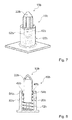
- FIGS. 6 to 8 a further embodiment of the invention is shown.
- the following description and the drawings are essentially limited to the differences between the exemplary embodiments, with respect to identically named components, in particular with regard to components having the same reference numerals, in principle also to the drawing and / or the description of the other embodiment, in particular FIGS. 1 to 5 , can be referenced.
- To distinguish the embodiments of the letter a is the reference numerals of the embodiment in the FIGS. 1 to 5 readjusted.
- the letter a is replaced by the letter b.
- FIGS. 6 to 8 show an Anpresstician 10b of another cooktop device in an enlarged exploded view (see. FIG. 6 ), in an assembled state (see. FIG. 7 ) and in a sectional view (see. FIG. 8 ).
- the further embodiment differs from the previous embodiment at least substantially by a sleeve unit 18b of the pressing unit 10b.
- a sleeve housing 20b is free of a sleeve housing mandrel. Furthermore, the sleeve housing 20b has a plurality of form-locking elements 54b. The form-locking elements 54b are formed as a rotation locking elements.
- a pressing element 22b is hollow in the present case.
- a wall thickness of the pressing element 22b is about 2 mm.
- the pressing element 22b has a shaft 52b.
- the shaft 52b is at least substantially cylindrical.
- the shaft 52a has a height and / or length of about 5 mm.
- the pressing element 22b further comprises a plurality of form-locking elements 54b.
- the positive-locking elements 54b are designed as rotary locking elements corresponding to the positive-locking elements 54b.
- FIGS. 7 and 8 show the pressing unit 10b in an assembled state.
- the sleeve housing 20b and the pressing member 22b are connected to each other in a direction parallel to a pressing force by a bayonet connection.
- the positive-locking elements 54b of the pressing element 22b engage behind the positive-locking elements 48b of the sleeve housing 20b.
- a movement of the pressing element 22b is limited by the positive-locking elements 54b and the interlocking elements 48b.
- the movement of the pressing member 22b is limited by a minimum longitudinal extent of an elastic member 12b.
Landscapes
- Engineering & Computer Science (AREA)
- General Engineering & Computer Science (AREA)
- Mechanical Engineering (AREA)
- Chemical & Material Sciences (AREA)
- Combustion & Propulsion (AREA)
- Physics & Mathematics (AREA)
- Acoustics & Sound (AREA)
- Aviation & Aerospace Engineering (AREA)
- Electromagnetism (AREA)
- Cookers (AREA)
- Baking, Grill, Roasting (AREA)
Abstract
Description
- Die Erfindung geht aus von einer Kochfeldvorrichtung nach dem Oberbegriff des Anspruchs 1.
- Aus dem Stand der Technik sind Induktionskochfelder bekannt, die eine Kochfeldplatte sowie ein federelastisches Element aufweisen, welches dazu vorgesehen ist, einen Induktor, insbesondere mittelbar, gegen eine Kochfeldplatte zu pressen.
- Die Aufgabe der Erfindung besteht insbesondere darin, eine gattungsgemäße Kochfeldvorrichtung mit verbesserten Eigenschaften hinsichtlich einer Anpressung bereitzustellen. Die Aufgabe wird durch die kennzeichnenden Merkmale des Patentanspruchs 1 gelöst, während vorteilhafte Ausgestaltungen und Weiterbildungen der Erfindung den Unteransprüchen entnommen werden können.
- Die Erfindung geht aus von einer Kochfeldvorrichtung, insbesondere einer Induktionskochfeldvorrichtung, mit zumindest einer Anpresseinheit, welche zumindest ein elastisches Element aufweist und welche dazu vorgesehen ist, zumindest eine Heizeinheit, insbesondere mittelbar, gegen eine Kochfeldplatte zu pressen.
- Es wird vorgeschlagen, dass die zumindest eine Anpresseinheit zumindest eine Hülseneinheit aufweist, welche das zumindest eine elastische Element in einem montierten Zustand zu wenigstens einem Großteil und vorzugsweise vollständig umschließt und/oder umgreift.
- Unter einer "Kochfeldvorrichtung" soll in diesem Zusammenhang insbesondere zumindest ein Teil, insbesondere eine Unterbaugruppe, eines Kochfelds, vorzugsweise eines Induktionskochfeldes, verstanden werden. Insbesondere kann die Kochfeldvorrichtung auch das gesamte Kochfeld, vorzugsweise das gesamte Induktionskochfeld, umfassen. Insbesondere kann die Kochfeldvorrichtung die zumindest eine Heizeinheit und/oder die Kochfeldplatte aufweisen, welche vorzugsweise zumindest teilweise, vorzugsweise zu wenigstens einem Großteil und besonders bevorzugt vollständig aus Glas und/oder Glaskeramik besteht. Unter dem Ausdruck "zu wenigstens einem Großteil" soll insbesondere zu zumindest 70 %, vorteilhaft zu zumindest 80 %, vorzugsweise zu zumindest 90 % und besonders bevorzugt zu zumindest 95 % verstanden werden. Die zumindest eine Heizeinheit kann insbesondere als Induktionsheizeinheit ausgebildet sein und insbesondere zumindest ein Heizelement, vorzugsweise einen Induktor, und insbesondere zumindest ein Trägerelement aufweisen, das insbesondere dazu vorgesehen ist, das zumindest eine Heizelement zu halten und/oder zu tragen. Das zumindest eine Trägerelement kann dabei aus einem beliebigen einem Fachmann als sinnvoll erscheinenden Material bestehen, wie beispielweise zumindest teilweise, vorzugsweise zu wenigstens einem Großteil und besonders bevorzugt vollständig aus Kunststoff, einem Verbundwerkstoff und/oder einem Metall, insbesondere Stahl, Edelstahl und/oder Aluminium. In diesem Zusammenhang soll unter einem "Heizelement" insbesondere ein Element verstanden werden, welches dazu vorgesehen ist, Energie, vorzugsweise elektrische Energie, in Wärme umzuwandeln und insbesondere einem Gargeschirr zuzuführen. Vorzugsweise ist das zumindest eine Heizelement dabei dazu vorgesehen, ein elektromagnetisches Wechselfeld, insbesondere mit einer Frequenz zwischen 20 kHz und 100 kHz, zu erzeugen, das insbesondere dazu vorgesehen ist, in einem aufgestellten, insbesondere metallischen, vorzugsweise ferromagnetischen, Gargeschirrboden durch Wirbelstrominduktion und/oder Ummagnetisierungseffekte in Wärme umgewandelt zu werden. Unter "vorgesehen" soll insbesondere speziell ausgelegt und/oder ausgestattet verstanden werden. Darunter, dass ein Objekt zu einer bestimmten Funktion vorgesehen ist, soll insbesondere verstanden werden, dass das Objekt diese bestimmte Funktion in zumindest einem Anwendungs- und/oder Betriebszustand erfüllt und/oder ausführt. Ferner kann die Kochfeldvorrichtung zumindest eine, vorzugsweise einstückige, Halteeinheit umfassen, welche insbesondere zumindest in einem montierten Zustand, vorzugsweise in dem montierten Zustand, dazu vorgesehen ist, die zumindest eine Heizeinheit, insbesondere das zumindest eine Heizelement und/oder das zumindest eine Trägerelement, vorteilhaft zumindest zwei, vorzugsweise zumindest drei und besonders bevorzugt zumindest vier Heizeinheiten und/oder eine Heizmatrix, welche insbesondere zumindest 4x2-Heizelemente, vorzugsweise zumindest 4x4-Heizelemente und besonders bevorzugt zumindest 8x8-Heizelemente umfasst, zumindest teilweise, vorzugsweise zu wenigstens einem Großteil, zu halten, zu stützen und/oder gegen die zumindest eine Kochfeldplatte zu pressen. In diesem Fall kann die zumindest eine Anpresseinheit insbesondere dazu vorgesehen sein, die zumindest eine Heizeinheit mittelbar gegen die zumindest eine Kochfeldplatte zu pressen. Insbesondere weist die zumindest eine Anpresseinheit in diesem Fall zumindest eine Kontaktfläche mit der zumindest einen Halteeinheit auf. Vorzugsweise ist die zumindest eine Halteeinheit dabei als Halteplatte ausgebildet. Die zumindest eine Halteeinheit kann insbesondere aus einem beliebigen einem Fachmann als sinnvoll erscheinenden Material bestehen, wie beispielweise zumindest teilweise, vorzugsweise zu wenigstens einem Großteil und besonders bevorzugt vollständig, aus Kunststoff, einem Verbundwerkstoff und/oder einem Metall, insbesondere Stahl, Edelstahl und/oder vorzugsweise Aluminium. Insbesondere kann die zumindest eine Halteeinheit einstückig mit einer Abschirmeinheit der Kochfeldvorrichtung zur Abschirmung einer Elektronikeinheit ausgebildet sein. Unter "einstückig" soll in diesem Zusammenhang insbesondere zumindest stoffschlüssig verbunden verstanden werden. Der Stoffschluss kann beispielsweise durch einen Klebeprozess, einen Schweißprozess, einen Lötprozess und/oder einen anderen, einem Fachmann als sinnvoll erscheinenden, Prozess hergestellt werden. Vorteilhaft soll unter einstückig jedoch in einem Stück geformt verstanden werden. Vorzugsweise wird dieses eine Stück aus einem einzelnen Rohling hergestellt. Ferner soll unter einem "elastischen Element" insbesondere ein Element, vorzugsweise ein Rückstellelement, verstanden werden, das zumindest einen Teilbereich aufweist, der in einem normalen Betriebszustand zumindest in seiner Position um zumindest 3 mm, vorteilhaft um zumindest 5 mm, vorzugsweise um zumindest 8 mm, elastisch veränderbar ist, und das insbesondere eine von einer Veränderung der Position abhängige und vorzugsweise zu der Veränderung proportionale Gegenkraft erzeugt, die insbesondere der Veränderung entgegen wirkt. Insbesondere ist das zumindest eine elastische Element wiederholt, insbesondere zumindest 100-mal, vorzugsweise zumindest 500-mal, insbesondere beschädigungsfrei, verformbar und strebt insbesondere nach einer Verformung selbstständig wieder einer Grundform zu. Vorzugsweise weist das zumindest eine elastische Element in einem montierten Zustand, insbesondere in einem montierten Zustand der zumindest einen Anpresseinheit und/oder in dem montierten Zustand, eine Vorspannung auf. Die zumindest eine Hülseneinheit kann insbesondere aus einem beliebigen einem Fachmann als sinnvoll erscheinenden, vorzugsweise nichtleitenden und/oder unmagnetischen, Material bestehen, wie beispielweise zumindest teilweise, vorzugsweise zu wenigstens einem Großteil und besonders bevorzugt vollständig aus Kunststoff und/oder einem Verbundwerkstoff. Alternativ ist jedoch auch denkbar, dass die zumindest eine Hülseneinheit zumindest teilweise, vorzugsweise zu wenigstens einem Großteil und besonders bevorzugt vollständig aus einem elektrisch leitenden Material, insbesondere einem Metall, vorzugsweise Aluminium, besteht, insbesondere um ein Potential, vorzugsweise ein Massepotential, besonders bevorzugt ein geerdetes Massepotential, an die zumindest eine Heizeinheit und/oder die zumindest eine Halteeinheit und/oder zumindest einen Teil der zumindest einen Heizeinheit und/oder der zumindest einen Halteeinheit anzulegen. Vorzugsweise ist die zumindest eine Hülseneinheit zumindest teilweise zwischen dem zumindest einen elastischen Element und der zumindest einen Heizeinheit und/oder der zumindest einen Halteeinheit angeordnet. Darunter, dass ein Objekt ein weiteres Objekt zumindest teilweise "umschließt" soll in diesem Zusammenhang insbesondere verstanden werden, dass zumindest eine von dem weiteren Objekt ausgehende Gerade zumindest einen Schnittpunkt mit dem Objekt aufweist. Darunter, dass ein Objekt ein weiteres Objekt zu wenigstens einem Großteil "umschließt" soll in diesem Zusammenhang insbesondere verstanden werden, dass zumindest 70 %, vorteilhaft zumindest 80 %, vorzugsweise zumindest 90 % und besonders bevorzugt zumindest 95 % aller möglichen von dem weiteren Objekt ausgehenden, insbesondere verschiedenen, Geraden zumindest einen Schnittpunkt mit dem Objekt aufweisen.
- Durch diese Ausgestaltung kann eine gattungsgemäße Gargerätevorrichtung mit verbesserten Eigenschaften hinsichtlich einer Anpressung bereitgestellt werden. Insbesondere kann eine vorteilhafte Schutzwirkung erreicht werden, insbesondere da ein mögliches Einklemmen von elektrischen Leitungen, insbesondere Kabeln, insbesondere durch das zumindest eine elastische Element, und/oder ein mögliches Abknicken des zumindest einen elastischen Elements vorteilhaft verhindert werden kann. Somit kann insbesondere eine Qualität und/oder eine Lebensdauer der Kochfeldvorrichtung vorteilhaft erhöht werden. Ferner kann insbesondere ein vorteilhafter Kraftübertrag, insbesondere eines Anpressdrucks, ermöglicht werden, so dass ein Kraftaufwand vorteilhaft minimiert werden kann.
- Das zumindest eine elastische Element könnte beispielweise als Polymer, als Elastomer und/oder als Silikonelement ausgebildet sein und/oder zumindest teilweise, vorzugsweise zu wenigstens einem Großteil und besonders bevorzugt vollständig aus einem Polymer, einem Elastomer und/oder Silikon bestehen. Vorzugsweise ist das zumindest eine elastische Element jedoch als eine Feder, insbesondere als eine Druckfeder, insbesondere eine Kegelfeder und/oder vorzugsweise eine Schraubenfeder, ausgebildet. Vorteilhaft besteht das zumindest eine elastische Element zumindest teilweise, vorzugsweise zu wenigstens einem Großteil und besonders bevorzugt vollständig aus, vorzugsweise gehärtetem, Stahl, insbesondere Federstahl. Alternativ ist denkbar, dass das zumindest eine elastische Element zumindest teilweise, vorzugsweise zu wenigstens einem Großteil und besonders bevorzugt vollständig aus einem Kunststoff, einer Legierung und/oder einem Verbundwerkstoff besteht. Insbesondere weist das zumindest eine elastische Element eine Federkonstante von höchstens 20 N/mm, vorteilhaft von höchstens 15 N/mm, vorzugsweise von höchstens 10 N/mm und besonders bevorzugt von höchstens 5 N/mm auf. Insbesondere weist das zumindest eine elastische Element eine Materialstärke von zumindest 0,5 mm, insbesondere zumindest 0,75 mm, und von maximal 4 mm, insbesondere maximal 3 mm, vorteilhaft maximal 2 mm, auf. Vorteilhaft ist das zumindest eine elastische Element zumindest teilweise, vorzugsweise zu wenigstens einem Großteil und besonders bevorzugt vollständig aus zumindest einem, vorzugsweise genau einem, Draht gebildet. In diesem Fall ist die Materialstärke insbesondere durch einen Durchmesser, insbesondere eines Querschnitts, des zumindest einen Drahts gegeben. Hierdurch kann insbesondere ein kostengünstiges sowie einfach aufgebautes elastisches Element bereitgestellt werden.
- Weist die zumindest eine Hülseneinheit zumindest ein, vorzugsweise genau ein, Hülsengehäuse und zumindest ein, vorzugsweise genau ein, insbesondere relativ zu dem zumindest einen Hülsengehäuse beweglich gelagertes Anpresselement auf, kann insbesondere eine kostengünstige Hülseneinheit bereitgestellt werden. Ferner kann ein Montageaufwand vorteilhaft verringert werden. Der Ausdruck "beweglich gelagert" soll in diesem Zusammenhang insbesondere eine Lagerung eines Objekts definieren, wobei das Objekt eine Bewegungsmöglichkeit entlang zumindest einer Strecke von zumindest 1 mm, vorzugsweise von zumindest 3 mm und besonders bevorzugt von zumindest 5 mm aufweist, insbesondere relativ zu einem weiteren Objekt. Das zumindest eine Hülsengehäuse weist dabei vorzugsweise zumindest einen Aufnahmebereich auf, welcher insbesondere durch zumindest eine Hülsengehäusewand, insbesondere eine Hülsengehäuseseitenwand, insbesondere eine Hülsengehäuseseitenfläche, und insbesondere zumindest einen Hülsengehäuseboden zumindest teilweise, insbesondere auf zumindest zwei und/oder fünf Seiten begrenzt ist.
- Ferner wird vorgeschlagen, dass das zumindest eine Hülsengehäuse das zumindest eine elastische Element im montierten Zustand zumindest in Umfangsrichtung zumindest teilweise, vorzugsweise wenigstens zu einem Großteil und besonders bevorzugt vollständig umschließt und/oder umgreift. Hierdurch kann insbesondere eine vorteilhaft einfache Schutzwirkung erreicht werden.
- In einer Ausgestaltung der Erfindung wird vorgeschlagen, dass das zumindest eine Hülsengehäuse das zumindest eine Anpresselement im montierten Zustand zumindest in Umfangsrichtung zumindest teilweise und vorzugsweise zu wenigstens einem Großteil umschließt und/oder umgreift. Alternativ ist jedoch auch denkbar, dass das zumindest eine Anpresselement das zumindest eine Hülsengehäuse im montierten Zustand zumindest in Umfangsrichtung zumindest teilweise und vorzugsweise zu wenigstens einem Großteil umschließt und/oder umgreift. Hierdurch kann insbesondere eine einfache Verbindung des zumindest einen Hülsengehäuses und des zumindest einen Anpresselements und/oder eine vorteilhafte Lagerung des zumindest einen Anpresselements erreicht werden.
- Des Weiteren wird vorgeschlagen, dass das zumindest eine Anpresselement im montierten Zustand von dem zumindest einen elastischen Element zumindest teilweise umschlossen und/oder umgriffen ist. Insbesondere weist das zumindest eine Anpresselement zumindest einen Schaft auf, insbesondere auf einer der zumindest einen Heizeinheit abgewandten Seite, welcher im montierten Zustand insbesondere von dem zumindest einen elastischen Element wenigstens in Umfangsrichtung zumindest teilweise, vorzugsweise zu wenigstens einem Großteil und besonders bevorzugt vollständig umschlossen und/oder umgriffen ist. Hierdurch kann insbesondere eine stabile und sichere Verbindung zwischen der zumindest einen Hülseneinheit und dem zumindest einen elastischen Element erreicht werden.
- Ist das zumindest eine Anpresselement zumindest teilweise konisch zulaufend ausgebildet, insbesondere auf einer der zumindest einen Heizeinheit zugewandten Seite, kann insbesondere ein Anpressdruck vorteilhaft übertragen werden. Ferner kann ein Einklemmen von elektrischen Leitungen, insbesondere durch das zumindest eine Anpresselement zumindest im Wesentlichen ausgeschlossen werden.
- In einer bevorzugten Ausgestaltung der Erfindung wird vorgeschlagen, dass das zumindest eine Hülsengehäuse und das zumindest eine Anpresselement im montierten Zustand in zumindest eine Richtung parallel zu einer Anpresskraft und/oder parallel zu einer Längserstreckung des zumindest einen Hülsengehäuses und/oder des zumindest einen elastischen Elements formschlüssig verbunden sind. Vorzugsweise sind das zumindest eine Hülsengehäuse und das zumindest eine Anpresselement im montierten Zustand ferner in zumindest eine Richtung senkrecht zu einer Anpresskraft und/oder senkrecht zu einer Längserstreckung des zumindest einen Hülsengehäuses und/oder des zumindest einen elastischen Elements formschlüssig verbunden. Darunter, dass ein Objekt mit einem weiteren Objekt "formschlüssig" verbunden ist, soll insbesondere verstanden werden, dass das Objekt zumindest ein Formschlusselement aufweist, welches, insbesondere in einem montierten Zustand, mit zumindest einem, insbesondere zu dem zumindest einen Formschlusselement korrespondierenden Formschlusselement des weiteren Objekts einen Formschluss bildet. Unter einer "Längserstreckung" eines Objekts soll in diesem Zusammenhang insbesondere eine längste Kante und/oder Seite eines kleinsten, das Objekt gerade noch umschließenden Quaders verstanden werden. Hierdurch kann insbesondere eine stabile und sichere Verbindung zwischen dem zumindest einen Hülsengehäuse und dem zumindest einen Anpresselement erreicht werden.
- Ferner wird vorgeschlagen, dass das zumindest eine Hülsengehäuse und das zumindest eine Anpresselement im montierten Zustand wenigstens durch eine Rastverbindung miteinander verbunden sind. Dazu weist das zumindest eine Hülsengehäuse und/oder das zumindest eine Anpresselement zumindest ein Rastelement, insbesondere einen, vorzugsweise federelastisch auslenkbaren, Rasthaken, eine Rastausnehmung und/oder eine Rastkante, auf. Hierdurch kann insbesondere eine einfache und schnelle Verbindung zwischen dem zumindest einen Hülsengehäuse und dem zumindest einen Anpresselement erreicht werden.
- Sind das zumindest eine Hülsengehäuse und das zumindest eine Anpresselement im montierten Zustand wenigstens durch eine Bajonettverbindung, insbesondere Drehverriegelung, miteinander verbunden, kann insbesondere eine vorteilhaft einfach lösbare Verbindung geschaffen werden.
- Weitere Vorteile ergeben sich aus der folgenden Zeichnungsbeschreibung. In der Zeichnung sind zwei Ausführungsbeispiele der Erfindung dargestellt. Die Zeichnung, die Beschreibung und die Ansprüche enthalten zahlreiche Merkmale in Kombination. Der Fachmann wird die Merkmale zweckmäßigerweise auch einzeln betrachten und zu sinnvollen weiteren Kombinationen zusammenfassen.
- Es zeigen:
- Fig. 1
- ein als Induktionskochfeld ausgebildetes Kochfeld mit einer Kochfeldvorrichtung in einer schematischen Draufsicht,
- Fig. 2
- ein Teil des Kochfelds in einer perspektivischen Seitenansicht,
- Fig. 3
- eine Explosionsdarstellung einer Anpresseinheit der Kochfeldvorrichtung in einer Seitenansicht,
- Fig. 4
- die Anpresseinheit aus
Figur 2 in einem montierten Zustand, - Fig. 5
- die Anpresseinheit aus
Figur 3 in einer Seitenansicht, - Fig. 6
- eine Explosionsdarstellung einer Anpresseinheit einer weiteren Kochfeldvorrichtung in einer Seitenansicht,
- Fig. 7
- die Anpresseinheit aus
Figur 5 in einem montierten Zustand und - Fig. 8
- die Anpresseinheit aus
Figur 6 in einer Schnittansicht. -
Figur 1 zeigt ein beispielhaftes als Induktionskochfeld ausgebildetes Kochfeld 24a in einer schematischen Draufsicht. Das Kochfeld 24a umfasst eine Kochfeldvorrichtung. Die Kochfeldvorrichtung weist eine Kochfeldplatte 16a auf. InFigur 1 ist dabei eine Außenseite 26a der Kochfeldplatte 16a gezeigt. Die Kochfeldplatte 16a besteht aus Glaskeramik. Die Kochfeldplatte 16a ist quaderförmig ausgebildet. Die Kochfeldplatte 16a umfasst vier Heizzonen 28a. -
Figur 2 zeigt einen Innenraum 30a des Kochfelds 24a. Die Kochfeldvorrichtung umfasst eine Gehäuseeinheit 32a. Die Gehäuseeinheit 32a besteht aus Aluminium. Die Gehäuseeinheit 32a ist zumindest im Wesentlichen wannenförmig ausgebildet. Die Gehäuseeinheit 32a und die Kochfeldplatte 16a begrenzen den Innenraum 30a des Kochfelds 24a. - Die Kochfeldvorrichtung umfasst eine Halteeinheit 34a. Die Halteeinheit 34a ist in dem Innenraum 30a angeordnet. Die Halteeinheit 34a ist als Halteplatte ausgebildet. Die Halteeinheit 34a ist einstückig ausgebildet. Im vorliegenden Fall besteht die Halteeinheit 34a aus Aluminium. Die Halteeinheit 34a ist zumindest im Wesentlichen quaderförmig ausgebildet. Die Halteeinheit 34a weist eine Länge von etwa 55 cm auf. Die Halteeinheit 34a weist eine Breite von etwa 50 cm auf. Ferner weist die Halteeinheit 34a eine konstante Materialstärke auf. Die Halteeinheit 34a weist eine Materialstärke von etwa 1,5 mm auf.
- Die Kochfeldvorrichtung weist zudem mehrere Heizeinheiten 14a auf. Im vorliegenden Fall umfasst die Kochfeldvorrichtung vier Heizeinheiten 14a. Jede Heizeinheit 14a ist dabei einer der Heizzonen 28a zugeordnet. Die Heizeinheiten 14a sind zumindest im Wesentlichen identisch miteinander ausgebildet. Die Heizeinheiten 14a sind in dem Innenraum 30a angeordnet. Die Heizeinheiten 14a sind zwischen der Kochfeldplatte 16a, insbesondere einer Innenseite der Kochfeldplatte 16a, und der Halteeinheit 34a angeordnet. Die Heizeinheiten 14a sind auf der Halteeinheit 34a befestigt. Jede der Heizeinheiten 14a weist dabei ein Trägerelement 36a auf. Ferner weist jede der Heizeinheiten 14a ein Heizelement 38a auf. Die Heizelemente 38a sind als Induktoren ausgebildet. Die Heizelemente 38a sind dazu vorgesehen, ein hochfrequentes Magnetfeld zu erzeugen, um Gargeschirr zu erhitzen. Die Heizelemente 38a sind jeweils auf einem der Trägerelemente 36a befestigt. Die Trägerelemente 36a sind im vorliegenden Fall im Vergleich zu den Heizelementen 38a in Richtung der Kochfeldplatte 16a um 2 mm erhöht ausgebildet. Alternativ ist auch denkbar, dass eine Heizeinheit mehrere Trägerelemente, insbesondere zumindest zwei und/oder zumindest drei Trägerelemente, und/oder mehrere Heizelemente, insbesondere zumindest zwei und/oder zumindest drei Heizelemente, umfasst. Ferner ist denkbar, dass Heizelemente im Vergleich zu Trägerelementen erhöht ausgebildet sind und/oder eine gleiche Höhe aufweisen. Alternativ ist auch denkbar, dass eine Kochfeldvorrichtung eine Heizmatrix aufweist, beispielweise mit 4x4-Heizelementen.
- Ferner weist die Kochfeldvorrichtung mehrere Anpresseinheiten 10a auf. Im vorliegenden Fall weist die Kochfeldvorrichtung neun Anpresseinheiten 10a auf. Alternativ kann eine Kochfeldvorrichtung auch eine andere Anzahl an Anpresseinheiten aufweisen, wie beispielweise zumindest zwei, zumindest vier, zumindest sechs, zumindest acht und/oder zumindest zehn Anpresseinheiten. Die Anpresseinheiten 10a sind miteinander identisch ausgebildet. Die Anpresseinheiten 10a sind zwischen der Gehäuseeinheit 32a und der Halteeinheit 34a angeordnet. Die Anpresseinheiten 10a sind an der Gehäuseeinheit 32a, insbesondere stoffschlüssig, befestigt. Ferner sind die Anpresseinheiten 10a mit der Halteeinheit 34a in Kontakt. Dabei weist jede der Anpresseinheiten 10a mit der Halteeinheit 34a eine Kontaktfläche auf. Die Anpresseinheiten 10a sind dazu vorgesehen, die Halteeinheit 34a in Richtung der Kochfeldplatte 16a zu drücken. Dabei sind die Anpresseinheiten 10a dazu vorgesehen, die Heizeinheiten 14a gegen die Kochfeldplatte 16a, insbesondere die Innenseite der Kochfeldplatte 16a, zu pressen. Im vorliegenden Fall sind die Anpresseinheiten 10a dazu vorgesehen, die Trägerelemente 36a unmittelbar gegen die Unterseite der Kochfeldplatte 16a zu pressen. Ein Abstand zwischen den Heizelementen 38a und der Unterseite der Kochfeldplatte 16a beträgt dabei 2 mm. Alternativ ist auch denkbar, dass Anpresseinheiten dazu vorgesehen sind, Heizelemente unmittelbar gegen eine Unterseite einer Kochfeldplatte zu pressen, so dass ein Abstand zwischen den Heizelementen und der Unterseite insbesondere 0 mm beträgt.
- Die
Figuren 3 bis 5 zeigen eine der Anpresseinheiten 10a in einer vergrößerten Explosionsdarstellung (vgl.Figur 3 ), in einem montierten Zustand (vgl.Figur 4 ) sowie in einer Seitenansicht (vgl.Figur 5 ). Die folgende Beschreibung beschränkt sich dabei auf eine der Anpresseinheiten 10a, kann jedoch für die anderen Anpresseinheiten 10a übernommen werden. - Die Anpresseinheit 10a weist ein elastisches Element 12a auf. Das elastische Element 12a ist als Schraubenfeder ausgebildet. Das elastische Element 12a besteht aus gehärtetem Federstahl. Das elastische Element 12a weist eine Materialstärke von 1 mm auf. Das elastische Element 12a weist in einem unbelasteten Zustand eine Längserstreckung von 23 mm auf. Das elastische Element 12a weist einen Radius von etwa 3,8 mm auf. Im vorliegenden Fall weist das elastische Element 12a eine Federkonstante von 3,2 N/mm auf.
- Ferner weist die Anpresseinheit 10a eine Hülseneinheit 18a auf. Die Hülseneinheit 18a besteht zumindest im Wesentlichen aus Polypropylen. Die Hülseneinheit 18a ist zweiteilig ausgebildet. Die Hülseneinheit 18a weist ein Hülsengehäuse 20a auf. Das Hülsengehäuse 20a ist im vorliegenden Fall der Übersichtlichkeit wegen durchsichtig dargestellt. Das Hülsengehäuse 20a ist einstückig ausgebildet. Das Hülsengehäuse 20a ist zumindest im Wesentlichen zylinderförmig. Das Hülsengehäuse 20a weist eine Höhe und/oder Länge von etwa 21 mm auf. Das Hülsengehäuse 20a weist einen Radius von etwa 4 mm auf. Das Hülsengehäuse 20a ist hohl ausgebildet. Eine Wandstärke des Hülsengehäuses 20a beträgt im vorliegenden Fall etwa 2 mm. Das Hülsengehäuse 20a weist einen Aufnahmebereich 40a auf. Der Aufnahmebereich 40a ist zu dem Hülsengehäuse 20a korrespondierend ausgebildet. Der Aufnahmebereich 40a ist durch eine Hülsengehäuseseitenfläche 42a und einen Hülsengehäuseboden 44a begrenzt. Demnach ist der Aufnahmebereich 40a in eine Richtung geöffnet. Der Aufnahmebereich 40a weist eine Öffnung in Richtung der Heizeinheit 14a und/oder der Kochfeldplatte 16a auf. Ferner weist das Hülsengehäuse 20a einen Hülsengehäusedorn 46a auf. Der Hülsengehäusedorn 46a ist an dem Hülsengehäuseboden 44a angeordnet. Der Hülsengehäusedorn 46a ist zumindest im Wesentlichen konisch ausgebildet. Der Hülsengehäusedorn 46a weist eine Höhe von etwa 8 mm auf. Ferner weist das Hülsengehäuse 20a mehrere Formschlusselemente 48a auf. Im vorliegenden Fall weist das Hülsengehäuse 20a drei Formschlusselemente 48a auf. Die Formschlusselemente 48a sind in einem Nahbereich der Öffnung angeordnet. Die Formschlusselemente 48a sind als Rastelemente ausgebildet. Die Formschlusselemente 48a sind als Rastkanten ausgebildet.
- Des Weiteren weist die Hülseneinheit 18a ein Anpresselement 22a auf. Das Anpresselement 22a ist einstückig ausgebildet. Das Anpresselement 22a weist einen Grundkörper 50a auf. Ein der Heizeinheit 14a und/oder der Kochfeldplatte 16a zugewandter erster Abschnitt des Grundkörpers 50a ist konisch zulaufend ausgebildet. Der erste Abschnitt weist eine Höhe und/oder Länge von etwa 7 mm auf. Der erste Abschnitt weist einen minimalen Radius von etwa 1,5 mm auf. Ein an den ersten Abschnitt angrenzender zweiter Abschnitt des Grundkörpers 50a ist zylinderförmig ausgebildet. Der zweite Abschnitt weist eine Höhe und/oder Länge von etwa 13 mm auf. Der zweite Abschnitt weist einen Radius von etwa 3,8 mm auf. Ferner weist das Anpresselement 22a einen Schaft 52a auf. Der Schaft 52a ist auf einer der Heizeinheit 14a und/oder der Kochfeldplatte 16a abgewandten Seite des Anpresselements 22a angeordnet. Der Schaft 52a weist eine Höhe und/oder Länge von etwa 3,5 mm auf. Der Schaft 52a ist zumindest im Wesentlichen zu dem elastischen Element 12a korrespondierend ausgebildet. Ferner weist das Anpresselement 22a mehrere Formschlusselemente 54a auf. Im vorliegenden Fall weist das Anpresselement 22a drei Formschlusselemente 54a auf. Die Formschlusselemente 54a sind an dem Grundkörper 50a, insbesondere dem zweiten Abschnitt des Grundkörpers 50a, angeordnet. Die Formschlusselemente 54a sind in einem Nahbereich des Schafts 52a angeordnet. Die Formschlusselemente 54a erstrecken sich zumindest im Wesentlichen über den gesamten zweiten Abschnitt des Grundkörpers 50a. Die Formschlusselemente 54a sind als Rastelemente ausgebildet. Die Formschlusselemente 54a sind als Rasthaken ausgebildet. Die Formschlusselemente 54a sind zu den Formschlusselementen 48a korrespondierend ausgebildet. Alternativ ist auch denkbar, dass Formschlusselemente eines Hülsengehäuses als Rasthaken ausgebildet sind und Formschlusselemente eines Anpresselements als Rastkanten. Ferner ist denkbar an einem Hülsengehäuse und/oder einem Anpresselement eine andere Anzahl an Formschlusselementen vorzusehen, insbesondere ein Formschlusselement, zwei Formschlusselemente und/oder vier Formschlusselemente.
- Die
Figuren 4 und 5 zeigen die Anpresseinheit 10a in einem montierten Zustand. In dem montierten Zustand bilden das Hülsengehäuse 20a und das Anpresselement 22a einen zumindest im Wesentlichen geschlossenen Aufnahmebereich für das elastische Element 12a. Dabei ist das Anpresselement 22a, insbesondere der Schaft 52a, zumindest teilweise in dem Aufnahmebereich 40a angeordnet. Somit umschließt das Hülsengehäuse 20a das Anpresselement 22a in Umfangsrichtung zumindest teilweise. Ferner verschließt das Anpresselement 22a die Öffnung des Aufnahmebereichs 40a. Dabei ist das Anpresselement 22a beweglich gelagert. Im vorliegenden Fall sind das Hülsengehäuse 20a und das Anpresselement 22a in einer Richtung parallel zu einer Anpresskraft durch eine Rastverbindung miteinander verbunden. Dabei hintergreifen die Formschlusselemente 54a des Anpresselements 22a die Formschlusselemente 48a des Hülsengehäuses 20a. - Ferner ist das elastische Element 12a vollständig in dem Aufnahmebereich 40a angeordnet. Dabei weist das elastische Element 12a eine Vorspannung auf. In dem montierten Zustand weist das elastische Element 12a eine Längserstreckung von 13 mm auf. Im vorliegenden Fall umschließt das Hülsengehäuse 20a das elastische Element 12a in Umfangsrichtung vollständig. Ferner umschließen der Hülsengehäuseboden 44a und das Anpresselement 22a die Längsseiten des elastischen Elements 12a vollständig. Demnach umschließt die Hülseneinheit 18a das elastische Element 12a vollständig. Das elastische Element 12a umschließt ferner den Schaft 52a des Anpresselements 22a. Zudem umschließt das elastische Element 12a den Hülsengehäusedorn 46a des Hülsengehäuses 20a. Der Hülsengehäusedorn 46a und/oder der Schaft 52a sind dazu vorgesehen, ein Ausknicken des elastischen Elements 12a zu verhindern und/oder das elastische Element 12a zu zentrieren.
- Im vorliegenden Fall kann sich das Anpresselement 22a entlang einer Strecke von etwa 8 mm in die Richtung parallel zu der Anpresskraft und/oder in Richtung der Heizeinheit 14a und/oder der Kochfeldplatte 16a bewegen. Eine Bewegung des Anpresselements 22a ist durch die Formschlusselemente 54a und die Formschlusselemente 48a begrenzt. Ferner ist die Bewegung des Anpresselements 22a durch den Hülsengehäusedorn 46a und/oder eine minimale Längserstreckung des elastischen Elements 12a begrenzt.
- In den
Figuren 6 bis 8 ist ein weiteres Ausführungsbeispiel der Erfindung gezeigt. Die nachfolgende Beschreibung und die Zeichnung beschränken sich im Wesentlichen auf die Unterschiede zwischen den Ausführungsbeispielen, wobei bezüglich gleich bezeichneter Bauteile, insbesondere in Bezug auf Bauteile mit gleichen Bezugszeichen, grundsätzlich auch auf die Zeichnung und/oder die Beschreibung des anderen Ausführungsbeispiels, insbesondere derFiguren 1 bis 5 , verwiesen werden kann. Zur Unterscheidung der Ausführungsbeispiele ist der Buchstabe a den Bezugszeichen des Ausführungsbeispiels in denFiguren 1 bis 5 nachgestellt. In dem Ausführungsbeispiel derFiguren 6 bis 8 ist der Buchstabe a durch den Buchstaben b ersetzt. - Die
Figuren 6 bis 8 zeigen eine Anpresseinheit 10b einer weiteren Kochfeldvorrichtung in einer vergrößerten Explosionsdarstellung (vgl.Figur 6 ), in einem montierten Zustand (vgl.Figur 7 ) sowie in einer Schnittansicht (vgl.Figur 8 ). Das weitere Ausführungsbeispiel unterscheidet sich von dem vorherigen Ausführungsbeispiel zumindest im Wesentlichen durch eine Hülseneinheit 18b der Anpresseinheit 10b. - Im vorliegenden Fall ist ein Hülsengehäuse 20b frei von einem Hülsengehäusedorn. Ferner weist das Hülsengehäuse 20b mehrere Formschlusselemente 54b auf. Die Formschlusselemente 54b sind als Drehverriegelungselemente ausgebildet.
- Zudem ist ein Anpresselement 22b im vorliegenden Fall hohl ausgebildet. Eine Wandstärke des Anpresselements 22b beträgt etwa 2 mm. Das Anpresselement 22b weist einen Schaft 52b auf. Der Schaft 52b ist zumindest im Wesentlichen zylinderförmig ausgebildet. Der Schaft 52a weist eine Höhe und/oder Länge von etwa 5 mm auf. Das Anpresselement 22b weist des Weiteren mehrere Formschlusselemente 54b auf. Die Formschlusselemente 54b sind als zu den Formschlusselementen 54b korrespondierende Drehverriegelungselemente ausgebildet.
- Die
Figuren 7 und 8 zeigen die Anpresseinheit 10b in einem montierten Zustand. Im vorliegenden Fall sind das Hülsengehäuse 20b und das Anpresselement 22b in einer Richtung parallel zu einer Anpresskraft durch eine Bajonettverbindung miteinander verbunden. Dabei hintergreifen, insbesondere durch Verdrehung des Anpresselements 22b, die Formschlusselemente 54b des Anpresselements 22b die Formschlusselemente 48b des Hülsengehäuses 20b. Dabei ist eine Bewegung des Anpresselements 22b durch die Formschlusselemente 54b und die Formschlusselemente 48b begrenzt. Ferner ist die Bewegung des Anpresselements 22b durch eine minimale Längserstreckung eines elastischen Elements 12b begrenzt. -
- 10
- Anpresseinheit
- 12
- elastisches Element
- 14
- Heizeinheit
- 16
- Kochfeldplatte
- 18
- Hülseneinheit
- 20
- Hülsengehäuse
- 22
- Anpresselement
- 24
- Kochfeld
- 26
- Außenseite
- 28
- Heizzone
- 30
- Innenraum
- 32
- Gehäuseeinheit
- 34
- Halteeinheit
- 36
- Trägerelement
- 38
- Heizelement
- 40
- Aufnahmebereich
- 42
- Hülsengehäuseseitenfläche
- 44
- Hülsengehäuseboden
- 46
- Hülsengehäusedorn
- 48
- Formschlusselement
- 50
- Grundkörper
- 52
- Schaft
- 54
- Formschlusselement
Claims (12)
- Kochfeldvorrichtung, insbesondere Induktionskochfeldvorrichtung, mit zumindest einer Anpresseinheit (10a; 10b), welche zumindest ein elastisches Element (12a; 12b) aufweist und welche dazu vorgesehen ist, zumindest eine Heizeinheit (14a; 14b) gegen eine Kochfeldplatte (16a; 16b) zu pressen, dadurch gekennzeichnet, dass die zumindest eine Anpresseinheit (10a; 10b) zumindest eine Hülseneinheit (18a; 18b) aufweist, welche das zumindest eine elastische Element (12a; 12b) in einem montierten Zustand zu wenigstens einem Großteil umschließt.
- Hausgerätevorrichtung nach Anspruch 1, dadurch gekennzeichnet, dass das zumindest eine elastische Element (12a; 12b) als eine Feder ausgebildet ist.
- Hausgerätevorrichtung nach Anspruch 1 oder 2, dadurch gekennzeichnet, dass die zumindest eine Hülseneinheit (18a; 18b) zumindest ein Hülsengehäuse (20a; 20b) und zumindest ein beweglich gelagertes Anpresselement (22a; 22b) aufweist.
- Hausgerätevorrichtung nach Anspruch 3, dadurch gekennzeichnet, dass das zumindest eine Hülsengehäuse (20a; 20b) das zumindest eine elastische Element (12a; 12b) im montierten Zustand zumindest in Umfangsrichtung zumindest teilweise umschließt.
- Hausgerätevorrichtung nach Anspruch 3 oder 4, dadurch gekennzeichnet, dass das zumindest eine Hülsengehäuse (20a; 20b) das zumindest eine Anpresselement (22a; 22b) im montierten Zustand zumindest in Umfangsrichtung zumindest teilweise umschließt.
- Hausgerätevorrichtung nach einem der Ansprüche 3 bis 5, dadurch gekennzeichnet, dass das zumindest eine Anpresselement (22a; 22b) im montierten Zustand von dem zumindest einen elastischen Element (12a; 12b) zumindest teilweise umschlossen ist.
- Hausgerätevorrichtung nach einem der Ansprüche 3 bis 6, dadurch gekennzeichnet, dass das zumindest eine Anpresselement (22a; 22b) zumindest teilweise konisch zulaufend ausgebildet ist.
- Hausgerätevorrichtung nach einem der Ansprüche 3 bis 7, dadurch gekennzeichnet, dass das zumindest eine Hülsengehäuse (20a; 20b) und das zumindest eine Anpresselement (22a; 22b) im montierten Zustand in zumindest eine Richtung parallel zu einer Anpresskraft formschlüssig verbunden sind.
- Hausgerätevorrichtung nach Anspruch 8, dadurch gekennzeichnet, dass das zumindest eine Hülsengehäuse (20a) und das zumindest eine Anpresselement (22a) im montierten Zustand wenigstens durch eine Rastverbindung miteinander verbunden sind.
- Hausgerätevorrichtung nach Anspruch 8 oder 9, dadurch gekennzeichnet, dass das zumindest eine Hülsengehäuse (20b) und das zumindest eine Anpresselement (22b) im montierten Zustand wenigstens durch eine Bajonettverbindung miteinander verbunden sind.
- Anpresseinheit (10a; 10b) für eine Kochfeldvorrichtung nach einem der vorhergehenden Ansprüche.
- Kochfeld (24a; 24b), insbesondere Induktionskochfeld, mit zumindest einer Kochfeldvorrichtung nach einem der Ansprüche 1 bis 10.
Applications Claiming Priority (1)
| Application Number | Priority Date | Filing Date | Title |
|---|---|---|---|
| ES201431011A ES2555707B1 (es) | 2014-07-04 | 2014-07-04 | Dispositivo de campo de cocción |
Publications (3)
| Publication Number | Publication Date |
|---|---|
| EP2975289A2 true EP2975289A2 (de) | 2016-01-20 |
| EP2975289A3 EP2975289A3 (de) | 2016-09-14 |
| EP2975289B1 EP2975289B1 (de) | 2022-09-07 |
Family
ID=54035094
Family Applications (1)
| Application Number | Title | Priority Date | Filing Date |
|---|---|---|---|
| EP15174723.5A Active EP2975289B1 (de) | 2014-07-04 | 2015-07-01 | Kochfeldvorrichtung |
Country Status (2)
| Country | Link |
|---|---|
| EP (1) | EP2975289B1 (de) |
| ES (2) | ES2555707B1 (de) |
Cited By (11)
| Publication number | Priority date | Publication date | Assignee | Title |
|---|---|---|---|---|
| EP3285009A1 (de) | 2016-08-16 | 2018-02-21 | Electrolux Appliances Aktiebolag | Andrückelement sowie induktionskochfeld mit einem andrückelement |
| EP3349543A1 (de) * | 2017-01-11 | 2018-07-18 | Gorenje Gospodinjski aparati d.d. | Induktionskochfeld |
| US10605464B2 (en) | 2012-10-15 | 2020-03-31 | Whirlpool Corporation | Induction cooktop |
| US10893579B2 (en) | 2017-07-18 | 2021-01-12 | Whirlpool Corporation | Method for operating an induction cooking hob and cooking hob using such method |
| US10993292B2 (en) | 2017-10-23 | 2021-04-27 | Whirlpool Corporation | System and method for tuning an induction circuit |
| US11140751B2 (en) | 2018-04-23 | 2021-10-05 | Whirlpool Corporation | System and method for controlling quasi-resonant induction heating devices |
| US11212880B2 (en) | 2012-10-15 | 2021-12-28 | Whirlpool Emea S.P.A. | Induction cooking top |
| US11310874B2 (en) | 2018-03-23 | 2022-04-19 | Whirlpool Corporation | Induction cooktop with improved magnetic flux concentrating foil |
| US11388785B2 (en) | 2018-03-23 | 2022-07-12 | Whirlpool Corporation | Connection interface for induction coil array |
| US11405989B2 (en) | 2018-03-23 | 2022-08-02 | Whirlpool Corporation | Temperature sensor compression features for induction cooktop assembly |
| WO2024085818A1 (en) * | 2022-10-19 | 2024-04-25 | Mamur Teknoloji Sistemleri San. A.S. | A bracket for a hob |
Family Cites Families (9)
| Publication number | Priority date | Publication date | Assignee | Title |
|---|---|---|---|---|
| ES2223258B1 (es) * | 2002-12-20 | 2006-04-16 | Bsh Electrodomesticos España, S.A. | Cocina de induccion. |
| US6996865B2 (en) * | 2003-05-23 | 2006-02-14 | Sabin Jeffrey M | Mattress structure |
| JP4375066B2 (ja) * | 2004-03-16 | 2009-12-02 | パナソニック株式会社 | 組み込み式加熱調理器 |
| CN100551176C (zh) * | 2004-08-25 | 2009-10-14 | 松下电器产业株式会社 | 感应加热烹调装置 |
| ES2328540B1 (es) * | 2006-08-07 | 2010-09-06 | Bsh Electrodomesticos España, S.A. | Dispositivo de sujecion de unidad calefactora. |
| US20100044367A1 (en) * | 2008-08-21 | 2010-02-25 | Lg Electronics Inc. | Induction heating device |
| CN102954506B (zh) * | 2011-08-27 | 2016-09-28 | 博西华电器(江苏)有限公司 | 电磁灶 |
| DE102012101929B4 (de) * | 2012-03-07 | 2015-02-19 | Federnfabrik Dietz Gmbh | Federhülse, Federstift und Verfahren und Vorrichtung zur Herstellung einer Federhülse und eines Federstifts |
| CN203657011U (zh) * | 2013-12-23 | 2014-06-18 | 美的集团股份有限公司 | 电磁炉 |
-
2014
- 2014-07-04 ES ES201431011A patent/ES2555707B1/es not_active Revoked
-
2015
- 2015-07-01 ES ES15174723T patent/ES2929559T3/es active Active
- 2015-07-01 EP EP15174723.5A patent/EP2975289B1/de active Active
Non-Patent Citations (1)
| Title |
|---|
| None |
Cited By (16)
| Publication number | Priority date | Publication date | Assignee | Title |
|---|---|---|---|---|
| US10605464B2 (en) | 2012-10-15 | 2020-03-31 | Whirlpool Corporation | Induction cooktop |
| US11655984B2 (en) | 2012-10-15 | 2023-05-23 | Whirlpool Corporation | Induction cooktop |
| US11212880B2 (en) | 2012-10-15 | 2021-12-28 | Whirlpool Emea S.P.A. | Induction cooking top |
| EP3285009A1 (de) | 2016-08-16 | 2018-02-21 | Electrolux Appliances Aktiebolag | Andrückelement sowie induktionskochfeld mit einem andrückelement |
| WO2018033371A1 (en) | 2016-08-16 | 2018-02-22 | Electrolux Appliances Aktiebolag | Pressing element and induction hob comprising a pressing element |
| CN109564001A (zh) * | 2016-08-16 | 2019-04-02 | 伊莱克斯家用电器股份公司 | 按压元件以及包括按压元件的感应灶具 |
| CN109564001B (zh) * | 2016-08-16 | 2020-08-21 | 伊莱克斯家用电器股份公司 | 按压元件以及包括按压元件的感应灶具 |
| AU2017312404B2 (en) * | 2016-08-16 | 2022-12-22 | Electrolux Appliances Aktiebolag | Pressing element and induction hob comprising a pressing element |
| EP3349543A1 (de) * | 2017-01-11 | 2018-07-18 | Gorenje Gospodinjski aparati d.d. | Induktionskochfeld |
| US10893579B2 (en) | 2017-07-18 | 2021-01-12 | Whirlpool Corporation | Method for operating an induction cooking hob and cooking hob using such method |
| US10993292B2 (en) | 2017-10-23 | 2021-04-27 | Whirlpool Corporation | System and method for tuning an induction circuit |
| US11405989B2 (en) | 2018-03-23 | 2022-08-02 | Whirlpool Corporation | Temperature sensor compression features for induction cooktop assembly |
| US11388785B2 (en) | 2018-03-23 | 2022-07-12 | Whirlpool Corporation | Connection interface for induction coil array |
| US11310874B2 (en) | 2018-03-23 | 2022-04-19 | Whirlpool Corporation | Induction cooktop with improved magnetic flux concentrating foil |
| US11140751B2 (en) | 2018-04-23 | 2021-10-05 | Whirlpool Corporation | System and method for controlling quasi-resonant induction heating devices |
| WO2024085818A1 (en) * | 2022-10-19 | 2024-04-25 | Mamur Teknoloji Sistemleri San. A.S. | A bracket for a hob |
Also Published As
| Publication number | Publication date |
|---|---|
| ES2929559T3 (es) | 2022-11-30 |
| ES2555707B1 (es) | 2016-10-11 |
| EP2975289A3 (de) | 2016-09-14 |
| ES2555707A1 (es) | 2016-01-07 |
| EP2975289B1 (de) | 2022-09-07 |
Similar Documents
| Publication | Publication Date | Title |
|---|---|---|
| EP2975289B1 (de) | Kochfeldvorrichtung | |
| EP2475220A1 (de) | Kochfeldvorrichtung | |
| DE102013218714A1 (de) | Kochfeldvorrichtung | |
| DE202009000990U1 (de) | Induktionsspulenträgervorrichtung | |
| DE102015220795A1 (de) | Kochfeldvorrichtung und Verfahren mit einer Kochfeldvorrichtung | |
| DE102015220788A1 (de) | Kochfeldvorrichtung und Verfahren zur Montage einer Kochfeldvorrichtung | |
| EP2079275A1 (de) | Induktionskochfeld mit einer Befestigungsvorrichtung zum Befestigen eines Induktorträgers an einem Montagerahmen | |
| EP2389541B1 (de) | Bedienvorrichtung eines haushaltsgeräts | |
| EP2578949B1 (de) | Hausgerät mit zumindest einer Trägereinheit umfassend zumindest eine Federeinheit | |
| DE102012219264A1 (de) | Hausgerätevorrichtung | |
| EP2389542B1 (de) | Bedienvorrichtung eines haushaltsgeräts | |
| EP2592899B1 (de) | Hausgerätevorrichtung | |
| EP2389785B1 (de) | Bedienvorrichtung eines haushaltsgeräts | |
| EP2443974B1 (de) | Gargeschirrboden | |
| EP2765827B1 (de) | Kochfeldvorrichtung | |
| EP3223586A1 (de) | Kochfeldvorrichtung | |
| EP2156706B1 (de) | Kochfeld | |
| WO2010084062A2 (de) | Bedienvorrichtung eines haushaltsgeräts | |
| EP4209117A1 (de) | Kochfeldvorrichtung und verfahren zum betrieb einer kochfeldvorrichtung | |
| EP3028538B1 (de) | Kochfeldvorrichtung | |
| DE102013207787A1 (de) | Kochfeldvorrichtung | |
| DE102018219969A1 (de) | Kochfeldvorrichtung | |
| WO2019166909A1 (de) | Garsystem | |
| WO2014045251A1 (de) | Kochfeldvorrichtung | |
| EP2881671B1 (de) | Kochfeldvorrichtung |
Legal Events
| Date | Code | Title | Description |
|---|---|---|---|
| PUAI | Public reference made under article 153(3) epc to a published international application that has entered the european phase |
Free format text: ORIGINAL CODE: 0009012 |
|
| AK | Designated contracting states |
Kind code of ref document: A2 Designated state(s): AL AT BE BG CH CY CZ DE DK EE ES FI FR GB GR HR HU IE IS IT LI LT LU LV MC MK MT NL NO PL PT RO RS SE SI SK SM TR |
|
| AX | Request for extension of the european patent |
Extension state: BA ME |
|
| PUAL | Search report despatched |
Free format text: ORIGINAL CODE: 0009013 |
|
| AK | Designated contracting states |
Kind code of ref document: A3 Designated state(s): AL AT BE BG CH CY CZ DE DK EE ES FI FR GB GR HR HU IE IS IT LI LT LU LV MC MK MT NL NO PL PT RO RS SE SI SK SM TR |
|
| AX | Request for extension of the european patent |
Extension state: BA ME |
|
| RIC1 | Information provided on ipc code assigned before grant |
Ipc: F16F 1/04 20060101ALI20160810BHEP Ipc: F16F 15/067 20060101AFI20160810BHEP Ipc: F24C 15/10 20060101ALI20160810BHEP Ipc: F16F 1/12 20060101ALI20160810BHEP |
|
| STAA | Information on the status of an ep patent application or granted ep patent |
Free format text: STATUS: REQUEST FOR EXAMINATION WAS MADE |
|
| 17P | Request for examination filed |
Effective date: 20170314 |
|
| RBV | Designated contracting states (corrected) |
Designated state(s): AL AT BE BG CH CY CZ DE DK EE ES FI FR GB GR HR HU IE IS IT LI LT LU LV MC MK MT NL NO PL PT RO RS SE SI SK SM TR |
|
| STAA | Information on the status of an ep patent application or granted ep patent |
Free format text: STATUS: EXAMINATION IS IN PROGRESS |
|
| 17Q | First examination report despatched |
Effective date: 20170530 |
|
| STAA | Information on the status of an ep patent application or granted ep patent |
Free format text: STATUS: EXAMINATION IS IN PROGRESS |
|
| GRAP | Despatch of communication of intention to grant a patent |
Free format text: ORIGINAL CODE: EPIDOSNIGR1 |
|
| STAA | Information on the status of an ep patent application or granted ep patent |
Free format text: STATUS: GRANT OF PATENT IS INTENDED |
|
| INTG | Intention to grant announced |
Effective date: 20220412 |
|
| GRAS | Grant fee paid |
Free format text: ORIGINAL CODE: EPIDOSNIGR3 |
|
| GRAA | (expected) grant |
Free format text: ORIGINAL CODE: 0009210 |
|
| STAA | Information on the status of an ep patent application or granted ep patent |
Free format text: STATUS: THE PATENT HAS BEEN GRANTED |
|
| AK | Designated contracting states |
Kind code of ref document: B1 Designated state(s): AL AT BE BG CH CY CZ DE DK EE ES FI FR GB GR HR HU IE IS IT LI LT LU LV MC MK MT NL NO PL PT RO RS SE SI SK SM TR |
|
| REG | Reference to a national code |
Ref country code: GB Ref legal event code: FG4D Free format text: NOT ENGLISH |
|
| REG | Reference to a national code |
Ref country code: CH Ref legal event code: EP Ref country code: AT Ref legal event code: REF Ref document number: 1517281 Country of ref document: AT Kind code of ref document: T Effective date: 20220915 |
|
| REG | Reference to a national code |
Ref country code: IE Ref legal event code: FG4D Free format text: LANGUAGE OF EP DOCUMENT: GERMAN |
|
| REG | Reference to a national code |
Ref country code: DE Ref legal event code: R096 Ref document number: 502015016053 Country of ref document: DE |
|
| REG | Reference to a national code |
Ref country code: ES Ref legal event code: FG2A Ref document number: 2929559 Country of ref document: ES Kind code of ref document: T3 Effective date: 20221130 |
|
| REG | Reference to a national code |
Ref country code: LT Ref legal event code: MG9D |
|
| REG | Reference to a national code |
Ref country code: NL Ref legal event code: MP Effective date: 20220907 |
|
| PG25 | Lapsed in a contracting state [announced via postgrant information from national office to epo] |
Ref country code: SE Free format text: LAPSE BECAUSE OF FAILURE TO SUBMIT A TRANSLATION OF THE DESCRIPTION OR TO PAY THE FEE WITHIN THE PRESCRIBED TIME-LIMIT Effective date: 20220907 Ref country code: RS Free format text: LAPSE BECAUSE OF FAILURE TO SUBMIT A TRANSLATION OF THE DESCRIPTION OR TO PAY THE FEE WITHIN THE PRESCRIBED TIME-LIMIT Effective date: 20220907 Ref country code: NO Free format text: LAPSE BECAUSE OF FAILURE TO SUBMIT A TRANSLATION OF THE DESCRIPTION OR TO PAY THE FEE WITHIN THE PRESCRIBED TIME-LIMIT Effective date: 20221207 Ref country code: LV Free format text: LAPSE BECAUSE OF FAILURE TO SUBMIT A TRANSLATION OF THE DESCRIPTION OR TO PAY THE FEE WITHIN THE PRESCRIBED TIME-LIMIT Effective date: 20220907 Ref country code: LT Free format text: LAPSE BECAUSE OF FAILURE TO SUBMIT A TRANSLATION OF THE DESCRIPTION OR TO PAY THE FEE WITHIN THE PRESCRIBED TIME-LIMIT Effective date: 20220907 Ref country code: FI Free format text: LAPSE BECAUSE OF FAILURE TO SUBMIT A TRANSLATION OF THE DESCRIPTION OR TO PAY THE FEE WITHIN THE PRESCRIBED TIME-LIMIT Effective date: 20220907 |
|
| PG25 | Lapsed in a contracting state [announced via postgrant information from national office to epo] |
Ref country code: HR Free format text: LAPSE BECAUSE OF FAILURE TO SUBMIT A TRANSLATION OF THE DESCRIPTION OR TO PAY THE FEE WITHIN THE PRESCRIBED TIME-LIMIT Effective date: 20220907 Ref country code: GR Free format text: LAPSE BECAUSE OF FAILURE TO SUBMIT A TRANSLATION OF THE DESCRIPTION OR TO PAY THE FEE WITHIN THE PRESCRIBED TIME-LIMIT Effective date: 20221208 |
|
| PG25 | Lapsed in a contracting state [announced via postgrant information from national office to epo] |
Ref country code: SM Free format text: LAPSE BECAUSE OF FAILURE TO SUBMIT A TRANSLATION OF THE DESCRIPTION OR TO PAY THE FEE WITHIN THE PRESCRIBED TIME-LIMIT Effective date: 20220907 Ref country code: RO Free format text: LAPSE BECAUSE OF FAILURE TO SUBMIT A TRANSLATION OF THE DESCRIPTION OR TO PAY THE FEE WITHIN THE PRESCRIBED TIME-LIMIT Effective date: 20220907 Ref country code: PT Free format text: LAPSE BECAUSE OF FAILURE TO SUBMIT A TRANSLATION OF THE DESCRIPTION OR TO PAY THE FEE WITHIN THE PRESCRIBED TIME-LIMIT Effective date: 20230109 Ref country code: CZ Free format text: LAPSE BECAUSE OF FAILURE TO SUBMIT A TRANSLATION OF THE DESCRIPTION OR TO PAY THE FEE WITHIN THE PRESCRIBED TIME-LIMIT Effective date: 20220907 |
|
| PG25 | Lapsed in a contracting state [announced via postgrant information from national office to epo] |
Ref country code: SK Free format text: LAPSE BECAUSE OF FAILURE TO SUBMIT A TRANSLATION OF THE DESCRIPTION OR TO PAY THE FEE WITHIN THE PRESCRIBED TIME-LIMIT Effective date: 20220907 Ref country code: PL Free format text: LAPSE BECAUSE OF FAILURE TO SUBMIT A TRANSLATION OF THE DESCRIPTION OR TO PAY THE FEE WITHIN THE PRESCRIBED TIME-LIMIT Effective date: 20220907 Ref country code: IS Free format text: LAPSE BECAUSE OF FAILURE TO SUBMIT A TRANSLATION OF THE DESCRIPTION OR TO PAY THE FEE WITHIN THE PRESCRIBED TIME-LIMIT Effective date: 20230107 Ref country code: EE Free format text: LAPSE BECAUSE OF FAILURE TO SUBMIT A TRANSLATION OF THE DESCRIPTION OR TO PAY THE FEE WITHIN THE PRESCRIBED TIME-LIMIT Effective date: 20220907 |
|
| REG | Reference to a national code |
Ref country code: DE Ref legal event code: R097 Ref document number: 502015016053 Country of ref document: DE |
|
| PG25 | Lapsed in a contracting state [announced via postgrant information from national office to epo] |
Ref country code: NL Free format text: LAPSE BECAUSE OF FAILURE TO SUBMIT A TRANSLATION OF THE DESCRIPTION OR TO PAY THE FEE WITHIN THE PRESCRIBED TIME-LIMIT Effective date: 20220907 Ref country code: AL Free format text: LAPSE BECAUSE OF FAILURE TO SUBMIT A TRANSLATION OF THE DESCRIPTION OR TO PAY THE FEE WITHIN THE PRESCRIBED TIME-LIMIT Effective date: 20220907 |
|
| PLBE | No opposition filed within time limit |
Free format text: ORIGINAL CODE: 0009261 |
|
| STAA | Information on the status of an ep patent application or granted ep patent |
Free format text: STATUS: NO OPPOSITION FILED WITHIN TIME LIMIT |
|
| PG25 | Lapsed in a contracting state [announced via postgrant information from national office to epo] |
Ref country code: DK Free format text: LAPSE BECAUSE OF FAILURE TO SUBMIT A TRANSLATION OF THE DESCRIPTION OR TO PAY THE FEE WITHIN THE PRESCRIBED TIME-LIMIT Effective date: 20220907 |
|
| 26N | No opposition filed |
Effective date: 20230608 |
|
| PG25 | Lapsed in a contracting state [announced via postgrant information from national office to epo] |
Ref country code: SI Free format text: LAPSE BECAUSE OF FAILURE TO SUBMIT A TRANSLATION OF THE DESCRIPTION OR TO PAY THE FEE WITHIN THE PRESCRIBED TIME-LIMIT Effective date: 20220907 |
|
| PGFP | Annual fee paid to national office [announced via postgrant information from national office to epo] |
Ref country code: IT Payment date: 20230731 Year of fee payment: 9 Ref country code: GB Payment date: 20230724 Year of fee payment: 9 Ref country code: ES Payment date: 20230821 Year of fee payment: 9 |
|
| PGFP | Annual fee paid to national office [announced via postgrant information from national office to epo] |
Ref country code: FR Payment date: 20230720 Year of fee payment: 9 Ref country code: DE Payment date: 20230731 Year of fee payment: 9 |
|
| PG25 | Lapsed in a contracting state [announced via postgrant information from national office to epo] |
Ref country code: MC Free format text: LAPSE BECAUSE OF FAILURE TO SUBMIT A TRANSLATION OF THE DESCRIPTION OR TO PAY THE FEE WITHIN THE PRESCRIBED TIME-LIMIT Effective date: 20220907 |
|
| PG25 | Lapsed in a contracting state [announced via postgrant information from national office to epo] |
Ref country code: MC Free format text: LAPSE BECAUSE OF FAILURE TO SUBMIT A TRANSLATION OF THE DESCRIPTION OR TO PAY THE FEE WITHIN THE PRESCRIBED TIME-LIMIT Effective date: 20220907 |
|
| REG | Reference to a national code |
Ref country code: CH Ref legal event code: PL |
|
| REG | Reference to a national code |
Ref country code: BE Ref legal event code: MM Effective date: 20230731 |
|
| PG25 | Lapsed in a contracting state [announced via postgrant information from national office to epo] |
Ref country code: LU Free format text: LAPSE BECAUSE OF NON-PAYMENT OF DUE FEES Effective date: 20230701 |
|
| PG25 | Lapsed in a contracting state [announced via postgrant information from national office to epo] |
Ref country code: LU Free format text: LAPSE BECAUSE OF NON-PAYMENT OF DUE FEES Effective date: 20230701 |
|
| REG | Reference to a national code |
Ref country code: IE Ref legal event code: MM4A |
|
| PG25 | Lapsed in a contracting state [announced via postgrant information from national office to epo] |
Ref country code: CH Free format text: LAPSE BECAUSE OF NON-PAYMENT OF DUE FEES Effective date: 20230731 |
|
| PG25 | Lapsed in a contracting state [announced via postgrant information from national office to epo] |
Ref country code: BE Free format text: LAPSE BECAUSE OF NON-PAYMENT OF DUE FEES Effective date: 20230731 |
|
| PG25 | Lapsed in a contracting state [announced via postgrant information from national office to epo] |
Ref country code: IE Free format text: LAPSE BECAUSE OF NON-PAYMENT OF DUE FEES Effective date: 20230701 |
|
| PG25 | Lapsed in a contracting state [announced via postgrant information from national office to epo] |
Ref country code: IE Free format text: LAPSE BECAUSE OF NON-PAYMENT OF DUE FEES Effective date: 20230701 |
|
| REG | Reference to a national code |
Ref country code: AT Ref legal event code: MM01 Ref document number: 1517281 Country of ref document: AT Kind code of ref document: T Effective date: 20230701 |