EP3012138B1 - Planenabdeckvorrichtung sowie ein damit ausgestatteter behälter mit einer oberen beladeöffnung - Google Patents
Planenabdeckvorrichtung sowie ein damit ausgestatteter behälter mit einer oberen beladeöffnung Download PDFInfo
- Publication number
- EP3012138B1 EP3012138B1 EP15189973.9A EP15189973A EP3012138B1 EP 3012138 B1 EP3012138 B1 EP 3012138B1 EP 15189973 A EP15189973 A EP 15189973A EP 3012138 B1 EP3012138 B1 EP 3012138B1
- Authority
- EP
- European Patent Office
- Prior art keywords
- winding core
- container
- tarpaulin
- winding
- hook section
- Prior art date
- Legal status (The legal status is an assumption and is not a legal conclusion. Google has not performed a legal analysis and makes no representation as to the accuracy of the status listed.)
- Active
Links
Images

Classifications
-
- B—PERFORMING OPERATIONS; TRANSPORTING
- B60—VEHICLES IN GENERAL
- B60J—WINDOWS, WINDSCREENS, NON-FIXED ROOFS, DOORS, OR SIMILAR DEVICES FOR VEHICLES; REMOVABLE EXTERNAL PROTECTIVE COVERINGS SPECIALLY ADAPTED FOR VEHICLES
- B60J7/00—Non-fixed roofs; Roofs with movable panels, e.g. rotary sunroofs
- B60J7/08—Non-fixed roofs; Roofs with movable panels, e.g. rotary sunroofs of non-sliding type, i.e. movable or removable roofs or panels, e.g. let-down tops or roofs capable of being easily detached or of assuming a collapsed or inoperative position
- B60J7/085—Non-fixed roofs; Roofs with movable panels, e.g. rotary sunroofs of non-sliding type, i.e. movable or removable roofs or panels, e.g. let-down tops or roofs capable of being easily detached or of assuming a collapsed or inoperative position winding up, e.g. for utility vehicles
Definitions
- the containers considered here are, in particular, load transport containers, in particular tipping bridges or dump bodies of load transport vehicles.
- Such containers with Planenabdeckvorraumen are known in various configurations.
- the Planenabdeckvorraumen can serve, for example, that in the container thermally isolate cargo, protect it from precipitation or prevent it from moving out of the container.
- the known load transport containers with tarpaulin covering device there are those in which the tarpaulin can be rolled out or rolled in the longitudinal direction of the load transfer container, which is usually rectangular in plan view.
- Other embodiments provide that the tarp can be rolled or curled transversely to the longitudinal direction of the container from one container side to the other side of the container lateral to cover or reopen the container.
- the Planenabdeckvorraum comprises a winding core and a turnable thereon tarpaulin, wherein the winding core can be guided over a laterally projecting from the container chip hook portion and hooked therein and fixed by a movable member without rotation restriction, to subsequently by rotating a movable jaw and engaging this in a gear of the winding core winding core also with respect to the rotation to fix.
- the tarpaulin covering device should be as uncomplicated as possible, reliable in operation and easy to operate.
- the present invention solves the problem of providing a tarpaulin covering device or a container with such a tarpaulin covering device which achieves the aforementioned objects.
- the inventive Planenabdeckvorraum characterized in that the to be fastened to the container engagement means to the winding core-locking position is resiliently biased, said ratchet mechanism at least a sprocket portion as a winding core side engaging means of the locking device, a plate with a hole cutout as a container-side engaging member and a handle for manual movement of the Plate in the winding core release position, wherein a lower edge of the hole cut-out of the plate is removed from the sprocket portion has.
- the ratchet mechanism facilitates the tensioning of the tarpaulin when rotating the winding core, by allowing further rotation of the winding core in the direction of increasing planetary tension, but automatically prevents unintentional turning back of the winding core by a locking operation of the engagement means and also by means of the handle enables a secure release of the locking / locking ,
- the turning operation of the winding core may be e.g. done manually by means of a crank.
- a motor drive is conceivable.
- the crank may be permanently connected to the winding core or, in alternative embodiments, may also be separable from the winding core.
- the tarpaulin tensioning device on a releasably connectable to the winding core crank means, on which the winding core side engagement means of the locking device is provided.
- the winding core side engagement means is a sprocket or at least one sprocket portion of the ratchet mechanism.
- the sprocket or sprocket portion may be formed of teeth which are convexly curved at their in relation to a certain direction of rotation of the winding core edges, so that they are resilient yield resilient locking edge of the container-side engaging means upon rotation of the winding core can displace in this direction without getting into locking engagement with the locking edge, whereas the teeth are formed at their leading with respect to the opposite direction of rotation edges, for example hook-shaped or the like Locking edge of the container-side engaging means lockingly engage, without being able to displace them.
- the container-side engagement means is movably biased between the winding core locking position and the core core release position by means of the force of a spring relative to the winding core locking position.
- the tensioning of the tarpaulin can proceed as follows: First, the winding core is rolled over the outwardly projecting tensioning hook section. The tarpaulin is largely unwound from the winding core, so that it hangs outside on the second side of the container on the unwound tarpaulin. Further rotation of the winding core then causes the tarpaulin to be rewound a bit - and the winding core is thereby lifted so that it engages the clamping hook section from below and thus arrives in its hooked state on the clamping hook section. At this point, it should be noted that preferably a plurality of clamping hook portions are arranged distributed along the second container side, which overlap the winding core together in its Einhak ein.
- the container-side engagement means of the locking device is mounted on the container such that the teeth of the sprocket portion come into contact with the locking edge of the container-side engaging means when the winding core is in its hooked state, but the direction of rotation of the winding core remains unchanged during tensioning of the tarpaulin such is that the convexly curved sides of the sprocket teeth in the direction of rotation run ahead and the container-side engagement means from its prestressed winding core locking position can displace.
- the winding core can be further rotated until the tarpaulin is sufficiently tensioned.
- a toothed ring tooth comes with its non-convex curved side lockingly engages the locking edge of the container-side engaging means and the tarpaulin is locked in its closed position and tensioned.
- the container-side engagement means against spring force in the hub release position to move, so that the sprocket teeth can no longer come into contact with the locking edge, after which the hub rotated out of its Einhak ein and finally back over the Spannhakenabitese can be rolled away to the first container side, wherein the tarpaulin is wound on the winding core.
- the winding core with the tarpaulin winding can then be placed on a winding core support on the first side of the container.
- the winding core is preferably a hollow rod made of a light metal, e.g. Aluminum.
- the sprocket portion of the locking device is preferably arranged at a first longitudinal end of the winding core.
- an elastic cable of a winding auxiliary device is provided on the first longitudinal end opposite second longitudinal end of the winding core, which is fixed on the one hand in the vicinity of the second container side to the container and on the other hand attached to an axial projection of the winding core at its second longitudinal end so that it can be wound on the winding core when the winding core is rotated for unwinding the tarpaulin, whereas it can be unwound from the winding core when the winding core is rotated to wind the tarpaulin, the winding auxiliary device being at the upper edge of the container in the same direction as the axial projection of the winding core projecting from the container deflecting over which the elastic cable is deflecting, when the winding core is rolled under development of the elastic rope to the first container side.
- the tarpaulin has at its edge attached to the winding core at least one cutout, which forms an open window for a clamping hook section, when the winding core is moved when spreading the tarpaulin over the clamping hook section. This allows a precise engagement of the winding core through the relevant clamping hook sections and prevents the tarpaulin in the region of the clamping hook sections being stressed during clamping.
- the tarpaulin covering device according to the invention is particularly suitable for a container, in particular load transport container of a load transport vehicle.
- a container according to the invention preferably according to the features of claim 6, wherein advantageous developments of the container according to the invention are the subject of claims 7 to 12.
- the tarpaulin covering device according to the invention may preferably have a modular design so that it can be mounted on a container in original equipment or can be provided as a retrofit kit for a container in order to form a container according to the invention.
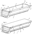
- the container 1 in FIG. 1 has an upper loading opening 3, which in FIG. 1 is exposed and coverable by means of a tarpaulin cover, as shown in FIG. 2 is shown.
- the tarpaulin covering device has a tarpaulin 5 of substantially rectangular blank in adaptation to the upper loading opening 3 to be covered.
- the tarpaulin 5 is wound substantially completely onto a winding core 7 of the tarpaulin covering device and is located at the upper end of a first side 9 of the container 1.
- the winding core 7 with the tarpaulin 5 wound thereon is supported on supporting elements 11 and thus secured to the container 1 ,
- the tarpaulin 5 is fixed on the one hand on top of the first side 9 of the container - and on the other hand on the winding core 7.
- the tarpaulin fixing to the winding core 7 is carried out so that the winding core winds the tarpaulin during its rotation without significant slippage.
- a crank 13 is provided, which is releasably attachable to the axially front end of the winding core and in the attached state rotationally fixed to the winding core. 7 connected is.
- the crank 13 is in FIG. 9 shown isolated.
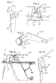
- FIG. 4 shows the cocking hook portion 17 at the front and upper container edge of the second container side 15 with the tarpaulin 5 removed therefrom.
- the winding core 7 was rotated to unwind the tarpaulin 5 by means of the crank 13 in a clockwise direction (seen from the front side 19 of the container 1) until it is in the in FIG. 4 position shown on the second container side 15 has come hanging, while the tarpaulin 5 has been unwound from a winding loop of the winding core 7.
- the hub according to the situation according to FIG. 4 further rotated in a clockwise direction by means of the crank 13, he winds the tarpaulin 5 again a little way and thereby passes up under the tensioning hook portion 17 and comes with this hooking into contact. Further rotation of the winding core 7 in the clockwise direction then causes the tarpaulin 5 is tensioned (see.
- a ratchet mechanism is effective, having a sprocket portion 21 on the circumference of the wound on the winding core 7 coaxially seated or alseuticden section 23 of the crank 13 as a winding core side engaging element and a plate 25 with a hole cutout 27 as a container-side engaging element.
- the plate 25 is secured by springs 28 to the fitting 29, which also the Clamping hook portion 17 and is bolted to the container.
- the plate 25 is movably mounted between a winding core-locking position and a winding core release position on the fitting 29 and resiliently biased to the winding core-locking position.
- the sprocket portion 21 of the locking device can engage with at least one tooth in the hole cutout 27 of the plate 25 when the winding core is hooked to the clamping hook portion 17 and the plate 25 is in its winding core-locking position.
- the teeth 31 of the sprocket portion 21 are shaped so that they rotate in accordance with their rotation of the winding core in accordance with FIG. 5 leading sides 33 are convex rounded, so that they can displace the plate 25 in each case from the winding core-locking position during rotation in a clockwise direction and it does not come to a locking of the locking device.
- the tarpaulin 5 can be stretched so comfortably.
- the lock between the sprocket portion 21 and the plate 25 is to be solved by the plate 25 from its winding core locking position according to FIG. 6 is moved to the winding core release position, in which the lower edge 37 of the hole cutout 27 of the plate 25 is removed from the sprocket portion 21.
- a handle 39 serves for manual movement of the plate 25 in the winding core release position.
- the winding core can then against the Clockwise (relative to FIG. 5 ) are rotated to wind the tarpaulin and the first container side in the open position according to FIG. 2 to get.
- the ratchet mechanism of resiliently displaceable plate 25 with hole recess 27 and sprocket portion 21 on the winding core 7 and the crank 13 is very simple and works very reliable and is also very easy to use to tension the tarpaulin or again from its closed position to solve.
- FIG. 10 shows a sectional view at the rear upper end of the second container side. It can be seen that the winding core 7 is extended at the rear end and that on the extended end of an elastic rope 40 is wound when the tarpaulin 5 is unwound from the winding core 7.
- the elastic cable 40 is fixed on the one hand in the vicinity of the second container side 15 to the container 1 and on the other hand attached to the axial projection of the winding core 7. If the tarpaulin 5 from the in FIG. 10 shown closed position rolled back onto the winding core, it comes to unroll the elastic line 40 of the axial supernatant of the winding core, wherein the elastic line 40 lays over a rod-shaped deflector 41 and is tensioned until finally the in FIG. 1 recognizable state is reached.
- the elastic line 40 and the deflection element 41 are components of a winding auxiliary device.
- the deflecting element 41 is according to FIG. 10 and FIG. 11 Component of a fitting 43, which also has a clamping hook portion 17.
- the fittings 29, 30 and 43 are components of the modular system of the tarpaulin tensioning device.
Landscapes
- Engineering & Computer Science (AREA)
- Mechanical Engineering (AREA)
- Details Of Rigid Or Semi-Rigid Containers (AREA)
- Storing, Repeated Paying-Out, And Re-Storing Of Elongated Articles (AREA)
Priority Applications (1)
| Application Number | Priority Date | Filing Date | Title |
|---|---|---|---|
| PL15189973T PL3012138T3 (pl) | 2014-10-21 | 2015-10-15 | Urządzenie do zakładania plandeki oraz wyposażony w nie kontener z górnym otworem załadunkowym |
Applications Claiming Priority (1)
| Application Number | Priority Date | Filing Date | Title |
|---|---|---|---|
| DE102014221384.3A DE102014221384A1 (de) | 2014-10-21 | 2014-10-21 | Planenabdeckvorrichtung sowie ein damit ausgestatteter Behälter mit einer oberen Beladeöffnung |
Publications (3)
| Publication Number | Publication Date |
|---|---|
| EP3012138A2 EP3012138A2 (de) | 2016-04-27 |
| EP3012138A3 EP3012138A3 (de) | 2016-05-18 |
| EP3012138B1 true EP3012138B1 (de) | 2019-12-11 |
Family
ID=54329449
Family Applications (1)
| Application Number | Title | Priority Date | Filing Date |
|---|---|---|---|
| EP15189973.9A Active EP3012138B1 (de) | 2014-10-21 | 2015-10-15 | Planenabdeckvorrichtung sowie ein damit ausgestatteter behälter mit einer oberen beladeöffnung |
Country Status (3)
| Country | Link |
|---|---|
| EP (1) | EP3012138B1 (pl) |
| DE (1) | DE102014221384A1 (pl) |
| PL (1) | PL3012138T3 (pl) |
Families Citing this family (1)
| Publication number | Priority date | Publication date | Assignee | Title |
|---|---|---|---|---|
| EP3892483B1 (de) | 2020-04-08 | 2022-08-24 | Schmitz Cargobull AG | Ladegutbehälter und fahrzeug |
Family Cites Families (7)
| Publication number | Priority date | Publication date | Assignee | Title |
|---|---|---|---|---|
| US31746A (en) | 1861-03-19 | Machine for splitting leather | ||
| USRE31746E (en) * | 1980-04-18 | 1984-11-27 | Wahpeton Canvas Company, Inc. | Roll-up tarp for trailers |
| US4505512A (en) * | 1982-12-06 | 1985-03-19 | Schmeichel Steven C | Roll-up tarp apparatus |
| US5380058A (en) * | 1993-04-08 | 1995-01-10 | Archer Daniels Midland Company | Hold cover for a vehicle especially one for transporting particulate matter |
| US6135534A (en) * | 1997-03-31 | 2000-10-24 | Schmeichel; Charles Milton | Truck box tarpaulin hold down |
| US6805395B2 (en) * | 2001-06-12 | 2004-10-19 | Royer Real | Tarpaulin rod securing device |
| US6478361B1 (en) * | 2001-10-22 | 2002-11-12 | Ronald L. Wood | Tarpaulin tightening device |
-
2014
- 2014-10-21 DE DE102014221384.3A patent/DE102014221384A1/de not_active Ceased
-
2015
- 2015-10-15 PL PL15189973T patent/PL3012138T3/pl unknown
- 2015-10-15 EP EP15189973.9A patent/EP3012138B1/de active Active
Non-Patent Citations (1)
| Title |
|---|
| None * |
Also Published As
| Publication number | Publication date |
|---|---|
| DE102014221384A1 (de) | 2016-05-04 |
| PL3012138T3 (pl) | 2020-06-29 |
| EP3012138A2 (de) | 2016-04-27 |
| EP3012138A3 (de) | 2016-05-18 |
Similar Documents
| Publication | Publication Date | Title |
|---|---|---|
| WO2002000467A1 (de) | Spannratsche mit gurtmagazin und gurtmagazin | |
| EP2786940A1 (de) | Beladestation für Transporttaschen zum hängenden Transport von Waren | |
| DE2716337A1 (de) | Befestigungsvorrichtung fuer container an einer wand | |
| EP1675749B1 (de) | Bandspanner und zugehörige spannbacken | |
| CH701261B1 (de) | Spanngurt. | |
| EP3012138B1 (de) | Planenabdeckvorrichtung sowie ein damit ausgestatteter behälter mit einer oberen beladeöffnung | |
| AT523897A1 (de) | Transportbehälter mit einer Verschlussanordnung | |
| DE4415042C1 (de) | Gurt-/Planspanner insbesondere für mit Spanngurten versehene Seitenplanen an Lkw-Aufbauten | |
| DE102008015632A1 (de) | Spanngurtratsche mit einer Gurtaufnahme | |
| AT500944B1 (de) | Vorrichtung zum spannen von seitenplanen eines fahrzeugaufbaus | |
| DE102007008916B4 (de) | Aufnahmevorrichtung für Paletten und Nutzfahrzeug mit einer derartigen Vorrichtung | |
| DE102007037439A1 (de) | Halter | |
| DE202016002322U1 (de) | Kurbel, Wickelmechanismus mit einer solchen Kurbel und Behälter mit einer Planenabdeckvorrichtung, die einen solchen Wickelmechanismus mit Kurbel umfasst | |
| DE2151817A1 (de) | Klinkenspanngeraet,insbesondere zum Spannen von Gewebe-,Papierbahnen usw. | |
| DE102004036773B4 (de) | Vorrichtung zur Befestigung von Lademodulen in einem Laderaum | |
| DE202009005903U1 (de) | Gurtspannvorrichtung | |
| DE102010024957A1 (de) | Ladungssicherungssystem für einen Kraftfahrzeugtransportraum | |
| AT520547B1 (de) | Abdeckung für Hochbeete | |
| EP1099585A2 (de) | Vorrichtung zur Abdeckung eines Behälters durch eine Abdeckplane | |
| EP3372067A1 (de) | Siloabdecksystem und silo | |
| DE102015113403B4 (de) | Ladungssicherungsgurtsystem und Spanngurt sowie Spanngurtgehäuse hierfür | |
| DE3811901A1 (de) | Rolladen | |
| DE102023132144A1 (de) | Heckklappe mit einer Verstaueinrichtung für ein Ladungssicherungsnetz | |
| DE102017117986B4 (de) | Transportvorrichtung zur Sicherung von Transportgut auf Fahrzeugen | |
| DE2408161B2 (de) | Handbetätigte Winde für aufrollbare Elemente |
Legal Events
| Date | Code | Title | Description |
|---|---|---|---|
| PUAL | Search report despatched |
Free format text: ORIGINAL CODE: 0009013 |
|
| PUAI | Public reference made under article 153(3) epc to a published international application that has entered the european phase |
Free format text: ORIGINAL CODE: 0009012 |
|
| AK | Designated contracting states |
Kind code of ref document: A2 Designated state(s): AL AT BE BG CH CY CZ DE DK EE ES FI FR GB GR HR HU IE IS IT LI LT LU LV MC MK MT NL NO PL PT RO RS SE SI SK SM TR |
|
| AX | Request for extension of the european patent |
Extension state: BA ME |
|
| AK | Designated contracting states |
Kind code of ref document: A3 Designated state(s): AL AT BE BG CH CY CZ DE DK EE ES FI FR GB GR HR HU IE IS IT LI LT LU LV MC MK MT NL NO PL PT RO RS SE SI SK SM TR |
|
| AX | Request for extension of the european patent |
Extension state: BA ME |
|
| RIC1 | Information provided on ipc code assigned before grant |
Ipc: B60J 7/08 20060101AFI20160408BHEP |
|
| 17P | Request for examination filed |
Effective date: 20160725 |
|
| RBV | Designated contracting states (corrected) |
Designated state(s): AL AT BE BG CH CY CZ DE DK EE ES FI FR GB GR HR HU IE IS IT LI LT LU LV MC MK MT NL NO PL PT RO RS SE SI SK SM TR |
|
| STAA | Information on the status of an ep patent application or granted ep patent |
Free format text: STATUS: EXAMINATION IS IN PROGRESS |
|
| 17Q | First examination report despatched |
Effective date: 20180913 |
|
| GRAP | Despatch of communication of intention to grant a patent |
Free format text: ORIGINAL CODE: EPIDOSNIGR1 |
|
| STAA | Information on the status of an ep patent application or granted ep patent |
Free format text: STATUS: GRANT OF PATENT IS INTENDED |
|
| INTG | Intention to grant announced |
Effective date: 20190628 |
|
| GRAS | Grant fee paid |
Free format text: ORIGINAL CODE: EPIDOSNIGR3 |
|
| GRAA | (expected) grant |
Free format text: ORIGINAL CODE: 0009210 |
|
| STAA | Information on the status of an ep patent application or granted ep patent |
Free format text: STATUS: THE PATENT HAS BEEN GRANTED |
|
| AK | Designated contracting states |
Kind code of ref document: B1 Designated state(s): AL AT BE BG CH CY CZ DE DK EE ES FI FR GB GR HR HU IE IS IT LI LT LU LV MC MK MT NL NO PL PT RO RS SE SI SK SM TR |
|
| REG | Reference to a national code |
Ref country code: GB Ref legal event code: FG4D Free format text: NOT ENGLISH |
|
| REG | Reference to a national code |
Ref country code: CH Ref legal event code: EP |
|
| REG | Reference to a national code |
Ref country code: AT Ref legal event code: REF Ref document number: 1211836 Country of ref document: AT Kind code of ref document: T Effective date: 20191215 |
|
| REG | Reference to a national code |
Ref country code: DE Ref legal event code: R096 Ref document number: 502015011187 Country of ref document: DE |
|
| REG | Reference to a national code |
Ref country code: IE Ref legal event code: FG4D Free format text: LANGUAGE OF EP DOCUMENT: GERMAN |
|
| REG | Reference to a national code |
Ref country code: NL Ref legal event code: MP Effective date: 20191211 |
|
| REG | Reference to a national code |
Ref country code: LT Ref legal event code: MG4D |
|
| PG25 | Lapsed in a contracting state [announced via postgrant information from national office to epo] |
Ref country code: SE Free format text: LAPSE BECAUSE OF FAILURE TO SUBMIT A TRANSLATION OF THE DESCRIPTION OR TO PAY THE FEE WITHIN THE PRESCRIBED TIME-LIMIT Effective date: 20191211 Ref country code: LV Free format text: LAPSE BECAUSE OF FAILURE TO SUBMIT A TRANSLATION OF THE DESCRIPTION OR TO PAY THE FEE WITHIN THE PRESCRIBED TIME-LIMIT Effective date: 20191211 Ref country code: LT Free format text: LAPSE BECAUSE OF FAILURE TO SUBMIT A TRANSLATION OF THE DESCRIPTION OR TO PAY THE FEE WITHIN THE PRESCRIBED TIME-LIMIT Effective date: 20191211 Ref country code: GR Free format text: LAPSE BECAUSE OF FAILURE TO SUBMIT A TRANSLATION OF THE DESCRIPTION OR TO PAY THE FEE WITHIN THE PRESCRIBED TIME-LIMIT Effective date: 20200312 Ref country code: NO Free format text: LAPSE BECAUSE OF FAILURE TO SUBMIT A TRANSLATION OF THE DESCRIPTION OR TO PAY THE FEE WITHIN THE PRESCRIBED TIME-LIMIT Effective date: 20200311 Ref country code: BG Free format text: LAPSE BECAUSE OF FAILURE TO SUBMIT A TRANSLATION OF THE DESCRIPTION OR TO PAY THE FEE WITHIN THE PRESCRIBED TIME-LIMIT Effective date: 20200311 Ref country code: FI Free format text: LAPSE BECAUSE OF FAILURE TO SUBMIT A TRANSLATION OF THE DESCRIPTION OR TO PAY THE FEE WITHIN THE PRESCRIBED TIME-LIMIT Effective date: 20191211 |
|
| PG25 | Lapsed in a contracting state [announced via postgrant information from national office to epo] |
Ref country code: HR Free format text: LAPSE BECAUSE OF FAILURE TO SUBMIT A TRANSLATION OF THE DESCRIPTION OR TO PAY THE FEE WITHIN THE PRESCRIBED TIME-LIMIT Effective date: 20191211 Ref country code: RS Free format text: LAPSE BECAUSE OF FAILURE TO SUBMIT A TRANSLATION OF THE DESCRIPTION OR TO PAY THE FEE WITHIN THE PRESCRIBED TIME-LIMIT Effective date: 20191211 |
|
| PG25 | Lapsed in a contracting state [announced via postgrant information from national office to epo] |
Ref country code: AL Free format text: LAPSE BECAUSE OF FAILURE TO SUBMIT A TRANSLATION OF THE DESCRIPTION OR TO PAY THE FEE WITHIN THE PRESCRIBED TIME-LIMIT Effective date: 20191211 |
|
| PG25 | Lapsed in a contracting state [announced via postgrant information from national office to epo] |
Ref country code: CZ Free format text: LAPSE BECAUSE OF FAILURE TO SUBMIT A TRANSLATION OF THE DESCRIPTION OR TO PAY THE FEE WITHIN THE PRESCRIBED TIME-LIMIT Effective date: 20191211 Ref country code: RO Free format text: LAPSE BECAUSE OF FAILURE TO SUBMIT A TRANSLATION OF THE DESCRIPTION OR TO PAY THE FEE WITHIN THE PRESCRIBED TIME-LIMIT Effective date: 20191211 Ref country code: PT Free format text: LAPSE BECAUSE OF FAILURE TO SUBMIT A TRANSLATION OF THE DESCRIPTION OR TO PAY THE FEE WITHIN THE PRESCRIBED TIME-LIMIT Effective date: 20200506 Ref country code: NL Free format text: LAPSE BECAUSE OF FAILURE TO SUBMIT A TRANSLATION OF THE DESCRIPTION OR TO PAY THE FEE WITHIN THE PRESCRIBED TIME-LIMIT Effective date: 20191211 Ref country code: ES Free format text: LAPSE BECAUSE OF FAILURE TO SUBMIT A TRANSLATION OF THE DESCRIPTION OR TO PAY THE FEE WITHIN THE PRESCRIBED TIME-LIMIT Effective date: 20191211 Ref country code: EE Free format text: LAPSE BECAUSE OF FAILURE TO SUBMIT A TRANSLATION OF THE DESCRIPTION OR TO PAY THE FEE WITHIN THE PRESCRIBED TIME-LIMIT Effective date: 20191211 |
|
| PG25 | Lapsed in a contracting state [announced via postgrant information from national office to epo] |
Ref country code: IS Free format text: LAPSE BECAUSE OF FAILURE TO SUBMIT A TRANSLATION OF THE DESCRIPTION OR TO PAY THE FEE WITHIN THE PRESCRIBED TIME-LIMIT Effective date: 20200411 Ref country code: SK Free format text: LAPSE BECAUSE OF FAILURE TO SUBMIT A TRANSLATION OF THE DESCRIPTION OR TO PAY THE FEE WITHIN THE PRESCRIBED TIME-LIMIT Effective date: 20191211 Ref country code: SM Free format text: LAPSE BECAUSE OF FAILURE TO SUBMIT A TRANSLATION OF THE DESCRIPTION OR TO PAY THE FEE WITHIN THE PRESCRIBED TIME-LIMIT Effective date: 20191211 |
|
| REG | Reference to a national code |
Ref country code: DE Ref legal event code: R097 Ref document number: 502015011187 Country of ref document: DE |
|
| PLBE | No opposition filed within time limit |
Free format text: ORIGINAL CODE: 0009261 |
|
| STAA | Information on the status of an ep patent application or granted ep patent |
Free format text: STATUS: NO OPPOSITION FILED WITHIN TIME LIMIT |
|
| PG25 | Lapsed in a contracting state [announced via postgrant information from national office to epo] |
Ref country code: DK Free format text: LAPSE BECAUSE OF FAILURE TO SUBMIT A TRANSLATION OF THE DESCRIPTION OR TO PAY THE FEE WITHIN THE PRESCRIBED TIME-LIMIT Effective date: 20191211 |
|
| 26N | No opposition filed |
Effective date: 20200914 |
|
| PG25 | Lapsed in a contracting state [announced via postgrant information from national office to epo] |
Ref country code: SI Free format text: LAPSE BECAUSE OF FAILURE TO SUBMIT A TRANSLATION OF THE DESCRIPTION OR TO PAY THE FEE WITHIN THE PRESCRIBED TIME-LIMIT Effective date: 20191211 |
|
| REG | Reference to a national code |
Ref country code: CH Ref legal event code: PL |
|
| GBPC | Gb: european patent ceased through non-payment of renewal fee |
Effective date: 20201015 |
|
| PG25 | Lapsed in a contracting state [announced via postgrant information from national office to epo] |
Ref country code: LU Free format text: LAPSE BECAUSE OF NON-PAYMENT OF DUE FEES Effective date: 20201015 Ref country code: MC Free format text: LAPSE BECAUSE OF FAILURE TO SUBMIT A TRANSLATION OF THE DESCRIPTION OR TO PAY THE FEE WITHIN THE PRESCRIBED TIME-LIMIT Effective date: 20191211 |
|
| REG | Reference to a national code |
Ref country code: BE Ref legal event code: MM Effective date: 20201031 |
|
| PG25 | Lapsed in a contracting state [announced via postgrant information from national office to epo] |
Ref country code: BE Free format text: LAPSE BECAUSE OF NON-PAYMENT OF DUE FEES Effective date: 20201031 Ref country code: CH Free format text: LAPSE BECAUSE OF NON-PAYMENT OF DUE FEES Effective date: 20201031 Ref country code: LI Free format text: LAPSE BECAUSE OF NON-PAYMENT OF DUE FEES Effective date: 20201031 Ref country code: GB Free format text: LAPSE BECAUSE OF NON-PAYMENT OF DUE FEES Effective date: 20201015 |
|
| PG25 | Lapsed in a contracting state [announced via postgrant information from national office to epo] |
Ref country code: IE Free format text: LAPSE BECAUSE OF NON-PAYMENT OF DUE FEES Effective date: 20201015 |
|
| PG25 | Lapsed in a contracting state [announced via postgrant information from national office to epo] |
Ref country code: TR Free format text: LAPSE BECAUSE OF FAILURE TO SUBMIT A TRANSLATION OF THE DESCRIPTION OR TO PAY THE FEE WITHIN THE PRESCRIBED TIME-LIMIT Effective date: 20191211 Ref country code: MT Free format text: LAPSE BECAUSE OF FAILURE TO SUBMIT A TRANSLATION OF THE DESCRIPTION OR TO PAY THE FEE WITHIN THE PRESCRIBED TIME-LIMIT Effective date: 20191211 Ref country code: CY Free format text: LAPSE BECAUSE OF FAILURE TO SUBMIT A TRANSLATION OF THE DESCRIPTION OR TO PAY THE FEE WITHIN THE PRESCRIBED TIME-LIMIT Effective date: 20191211 |
|
| PG25 | Lapsed in a contracting state [announced via postgrant information from national office to epo] |
Ref country code: MK Free format text: LAPSE BECAUSE OF FAILURE TO SUBMIT A TRANSLATION OF THE DESCRIPTION OR TO PAY THE FEE WITHIN THE PRESCRIBED TIME-LIMIT Effective date: 20191211 |
|
| PGFP | Annual fee paid to national office [announced via postgrant information from national office to epo] |
Ref country code: DE Payment date: 20250929 Year of fee payment: 11 |
|
| PGFP | Annual fee paid to national office [announced via postgrant information from national office to epo] |
Ref country code: AT Payment date: 20251022 Year of fee payment: 11 |
|
| PGFP | Annual fee paid to national office [announced via postgrant information from national office to epo] |
Ref country code: IT Payment date: 20251024 Year of fee payment: 11 |
|
| PGFP | Annual fee paid to national office [announced via postgrant information from national office to epo] |
Ref country code: FR Payment date: 20251030 Year of fee payment: 11 |
|
| PGFP | Annual fee paid to national office [announced via postgrant information from national office to epo] |
Ref country code: PL Payment date: 20251006 Year of fee payment: 11 |