EP3010645B1 - Dispositif pour transporter de la poudre de revetement - Google Patents
Dispositif pour transporter de la poudre de revetement Download PDFInfo
- Publication number
- EP3010645B1 EP3010645B1 EP14726961.7A EP14726961A EP3010645B1 EP 3010645 B1 EP3010645 B1 EP 3010645B1 EP 14726961 A EP14726961 A EP 14726961A EP 3010645 B1 EP3010645 B1 EP 3010645B1
- Authority
- EP
- European Patent Office
- Prior art keywords
- powder
- valve
- operating mode
- pressure
- conveying
- Prior art date
- Legal status (The legal status is an assumption and is not a legal conclusion. Google has not performed a legal analysis and makes no representation as to the accuracy of the status listed.)
- Active
Links
Images


Classifications
-
- B—PERFORMING OPERATIONS; TRANSPORTING
- B65—CONVEYING; PACKING; STORING; HANDLING THIN OR FILAMENTARY MATERIAL
- B65G—TRANSPORT OR STORAGE DEVICES, e.g. CONVEYORS FOR LOADING OR TIPPING, SHOP CONVEYOR SYSTEMS OR PNEUMATIC TUBE CONVEYORS
- B65G53/00—Conveying materials in bulk through troughs, pipes or tubes by floating the materials or by flow of gas, liquid or foam
- B65G53/34—Details
- B65G53/66—Use of indicator or control devices, e.g. for controlling gas pressure, for controlling proportions of material and gas, for indicating or preventing jamming of material
-
- B—PERFORMING OPERATIONS; TRANSPORTING
- B05—SPRAYING OR ATOMISING IN GENERAL; APPLYING FLUENT MATERIALS TO SURFACES, IN GENERAL
- B05B—SPRAYING APPARATUS; ATOMISING APPARATUS; NOZZLES
- B05B7/00—Spraying apparatus for discharge of liquids or other fluent materials from two or more sources, e.g. of liquid and air, of powder and gas
- B05B7/14—Spraying apparatus for discharge of liquids or other fluent materials from two or more sources, e.g. of liquid and air, of powder and gas designed for spraying particulate materials
- B05B7/1404—Arrangements for supplying particulate material
- B05B7/1459—Arrangements for supplying particulate material comprising a chamber, inlet and outlet valves upstream and downstream the chamber and means for alternately sucking particulate material into and removing particulate material from the chamber through the valves
-
- B—PERFORMING OPERATIONS; TRANSPORTING
- B65—CONVEYING; PACKING; STORING; HANDLING THIN OR FILAMENTARY MATERIAL
- B65G—TRANSPORT OR STORAGE DEVICES, e.g. CONVEYORS FOR LOADING OR TIPPING, SHOP CONVEYOR SYSTEMS OR PNEUMATIC TUBE CONVEYORS
- B65G53/00—Conveying materials in bulk through troughs, pipes or tubes by floating the materials or by flow of gas, liquid or foam
- B65G53/04—Conveying materials in bulk pneumatically through pipes or tubes; Air slides
- B65G53/06—Gas pressure systems operating without fluidisation of the materials
- B65G53/10—Gas pressure systems operating without fluidisation of the materials with pneumatic injection of the materials by the propelling gas
- B65G53/14—Gas pressure systems operating without fluidisation of the materials with pneumatic injection of the materials by the propelling gas the gas flow inducing feed of the materials by suction effect
-
- B—PERFORMING OPERATIONS; TRANSPORTING
- B65—CONVEYING; PACKING; STORING; HANDLING THIN OR FILAMENTARY MATERIAL
- B65G—TRANSPORT OR STORAGE DEVICES, e.g. CONVEYORS FOR LOADING OR TIPPING, SHOP CONVEYOR SYSTEMS OR PNEUMATIC TUBE CONVEYORS
- B65G53/00—Conveying materials in bulk through troughs, pipes or tubes by floating the materials or by flow of gas, liquid or foam
- B65G53/04—Conveying materials in bulk pneumatically through pipes or tubes; Air slides
- B65G53/28—Systems utilising a combination of gas pressure and suction
-
- F—MECHANICAL ENGINEERING; LIGHTING; HEATING; WEAPONS; BLASTING
- F16—ENGINEERING ELEMENTS AND UNITS; GENERAL MEASURES FOR PRODUCING AND MAINTAINING EFFECTIVE FUNCTIONING OF MACHINES OR INSTALLATIONS; THERMAL INSULATION IN GENERAL
- F16K—VALVES; TAPS; COCKS; ACTUATING-FLOATS; DEVICES FOR VENTING OR AERATING
- F16K7/00—Diaphragm valves or cut-off apparatus, e.g. with a member deformed, but not moved bodily, to close the passage ; Pinch valves
- F16K7/02—Diaphragm valves or cut-off apparatus, e.g. with a member deformed, but not moved bodily, to close the passage ; Pinch valves with tubular diaphragm
- F16K7/04—Diaphragm valves or cut-off apparatus, e.g. with a member deformed, but not moved bodily, to close the passage ; Pinch valves with tubular diaphragm constrictable by external radial force
- F16K7/07—Diaphragm valves or cut-off apparatus, e.g. with a member deformed, but not moved bodily, to close the passage ; Pinch valves with tubular diaphragm constrictable by external radial force by means of fluid pressure
-
- G—PHYSICS
- G05—CONTROLLING; REGULATING
- G05D—SYSTEMS FOR CONTROLLING OR REGULATING NON-ELECTRIC VARIABLES
- G05D7/00—Control of flow
- G05D7/01—Control of flow without auxiliary power
- G05D7/0106—Control of flow without auxiliary power the sensing element being a flexible member, e.g. bellows, diaphragm, capsule
- G05D7/012—Control of flow without auxiliary power the sensing element being a flexible member, e.g. bellows, diaphragm, capsule the sensing element being deformable and acting as a valve
Definitions
- the present invention relates to a powder conveying device, in particular for coating powder, wherein the powder conveying device comprises a powder sealant pump and a control device for selectively operating the powder sealant pump in a powder feed operating mode or a rinse operating mode.
- the powder conveying device according to the invention is particularly suitable for conveying coating powder from a first powder reservoir to a second powder reservoir located downstream of the powder conveying device or a powder spray coating gun or powder coating device arranged downstream of the powder conveying device or the like device for spraying coating powder.
- the invention further relates to a method for conveying coating powder from a first powder reservoir to a second powder reservoir arranged downstream of a first powder reservoir or to a powder spray coating gun arranged downstream of the first powder reservoir or to the same device for spraying coating powder.
- Powder conveying devices of the type mentioned are known in principle from the prior art.
- German patent application no. 10 2013 205 895.0 a powder delivery device with a dense phase powder pump (dense phase powder pump), said powder seal pump is controlled by means of a control device such that in a powder conveying operating mode of the powder sealant pump coating powder is conveyed from a first powder reservoir to a second powder reservoir arranged downstream of the first powder reservoir or to a downstream powder spray coating gun.
- the document relates EP 1 551 558 A1 a powder sealant pump having a first powder feed chamber and a second powder feed chamber arranged parallel to the first powder feed chamber.
- the two powder feed chambers of the powder seal current pump known from this prior art are limited both on the intake side and on the delivery side in each case by a mechanically actuated pinch valve arrangement.
- the powder seal pump of the powder feeder may be selectively operated in a powder feed mode of operation or in a purge mode of operation.
- the powder sealant pump conveys powdery material, particularly coating powder, from a first powder reservoir to a second powder reservoir located downstream of the powder conveying device or a powder spray coating gun or powder coating spraying device downstream of the powder conveying device.
- the powder seal pump and the powder lines connected to the powder seal pump are flushed with purge gas, in particular compressed air, and thus cleaned.
- the object of the present invention is, in particular, to develop a powder conveying device of the type mentioned at the outset such that a more efficient operation of the powder conveying device in the powder conveying operating mode and the rinsing operating mode is possible.
- the pressure value of the selected to close the powder inlet and / or powder outlet valve actuating pressure is lower than the pressure value of the corresponding actuating pressure in the purge operating mode of the powder seal, wherein the pressure level with a pressure sensor the actuating air is detected.
- control device is designed to automatically and more preferably selectively, depending on the operating mode of the powder sealant pump, the pressure value of a compressed gas to be introduced into the delivery chamber and / or the amount of compressed gas to be introduced into the delivery chamber per unit time set automatically.
- transport compressed gas in particular transport compressed air
- this transport compressed gas is at a first pressure level.
- purge compressed gas in particular purge compressed air
- purge compressed gas can then be introduced into the delivery chamber, for which purpose a higher (second) pressure level than the first pressure level is selected.
- the cleaning efficiency is optimized.
- the pressure value of the selected for closing the powder inlet valve and / or powder outlet valve actuating pressure is set in dependence on the respective operating mode of the powder seal pump or in dependence on a pressure prevailing in the delivery chamber, it is ensured that even then the closed powder inlet valve or the closed Powder outlet valve can pass no flushing gas when a correspondingly higher pressure is selected for the flushing gas.
- the control device is designed as a function of a quantity of transport compressed gas fed per unit time in the powder conveying operating mode and / or in a quantity delivered per unit time in the powder feed operating mode by the powder sealant pump to coating powder, the pressure value of the selected for closing the powder inlet valve and / or powder outlet valve actuating pressure preferably automatically and more preferably optionally automatically.
- the operating pressure of the pinch valves can thus be adjusted depending on the output of the powder seal pump.
- the powder sealant pump can be easily used for special powder types where powder blocking easily occurs.
- powder feed operation mode means an operation mode of the powder seal pump in which a powder portion is alternately sucked into the feed chamber of the powder seal pump through the opened powder inlet valve while the powder discharge valve is closed and through the opened powder discharge valve which is previously in the Delivery chamber sucked powder portion is discharged by introducing transport compressed gas into the delivery chamber, while the powder inlet valve is closed.
- scavenging operating mode is to be understood in particular as an operating mode in which the powder inlet valve and / or the powder outlet valve is opened while scavenging compressed gas is introduced into the conveying chamber simultaneously or with a time delay.
- control device has a pressure control which is designed to set a pressure value of a transport compressed gas to be introduced into the delivery chamber during the powder delivery operating mode.
- the latter has at least one throttle device in order to be able to locally adjust a flow cross-section of a compressed gas line which is fluidically connected or connectable to the delivery chamber of the powder sealant pump.
- the throttle device has at least one throttle valve, in particular in the form of a control valve, which is designed to set a pressure value of the transport compressed gas to be introduced into the feed chamber during the powder feed operating mode and / or to set one per unit time during the powder feed Operating mode in the delivery chamber to be introduced amount of transport compressed gas.
- the at least one throttle valve is preferably also configured to deliver a pressure value of the purge compressed gas to be introduced into the delivery chamber during the purge mode of operation and / or an amount of purge compressed gas to be introduced into the delivery chamber during the purge operating mode adjust.
- the throttle valve has a stationary valve member, in particular in the form of a valve seat, and a relatively movable and thus adjustable valve member for varying the opening width of a throttle channel of the at least one throttle valve, wherein the geometric shape of adjustable valve part is selected so that the throttle valve has a flow characteristic with at least two substantially linear regions.
- the at least two substantially linear regions of the flow characteristic have predetermined, different gradients.
- control device is designed to control the throttle valve in the powder feed operating mode such that the compressed gas flow through the throttle valve is in a first substantially linear region of the flow characteristic, and to control the throttle valve in the purge operating mode in that the compressed gas flow through the throttle valve is in a second substantially linear region of the flow characteristic.
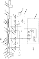
- the powder conveying device 100 is used in particular for conveying coating powder from a first powder reservoir 101 to a powder spray coating gun 102 arranged downstream of the powder conveying device 100.
- a powder spray coating gun 102 instead of the powder spray coating gun 102, another device for spraying coating powder onto an object to be coated or else a second powder reservoir can also be used Use come.
- the powder conveying device 100 has at least one (in the drawing Fig. 1 exactly one) powder sealant pump 1.
- the powder inlet 2 of the powder sealant flow pump 1 is connected or connectable to the first powder reservoir 101 by means of a powder line 103, in particular by means of an intake pipe or the like.
- a powder outlet 3 is provided, which is connected or connectable by means of a powder line 104, in particular with the aid of a powder hose, to a coating powder inlet 105 of the powder spray coating gun 102.
- both the powder inlet 2 and the powder outlet 3 of the powder sealant pump 1 are each designed as hose connection pieces to which the corresponding powder line 103 or 104 can be attached and fixed with a hose clamp.
- the powder inlet 2 and the powder outlet 3 of the powder seal current pump 1 come into question.
- the at the in Fig. 1 Among other things, it is characterized in that it is designed as a single-chamber Pulverdichtstromstrompumpe, wherein for conveying coating powder from the first powder reservoir 101 to the powder spray coating gun 102 and to another device for Spray coating of objects or to a further powder reservoir only a single powder feed chamber 4 is provided.
- the invention is not limited to powder feeders using a single chamber powder seal pump. Rather, the invention also includes such powder conveying devices in which multi-chamber powder seal pumps are used.
- the powder sealant pump 1 which in the in Fig. 1 Here, however, is formed as a single-chamber powder seal pump, wherein for conveying powder coating from the first powder reservoir 1 to the powder spray coating gun 102 or to another means for spray coating of objects or to another powder reservoir only one only powder conveying chamber 4 is provided.
- This powder conveying chamber 4 has at a first end region a powder inlet 5 which points in the direction of the powder inlet 2 of the powder sealant flow pump 1. Furthermore, the powder conveying chamber 4 has a powder outlet 6 pointing in the direction of the powder outlet 3 of the powder seal pump.
- a powder inlet valve 7 is disposed immediately adjacent the powder inlet 5 of the powder delivery chamber 4, in such a way that this powder inlet valve 7 lies between the powder inlet 5 of the powder delivery chamber 4 and the powder inlet 2 of the powder sealant pump 1.
- a powder outlet valve 8 is arranged immediately adjacent to the powder outlet 6 of the powder conveying chamber 4.
- the powder outlet valve 8 is not disposed directly between the powder outlet 6 of the powder conveying chamber 4 and the powder outlet 3 of the powder sealing current pump 1 at the powder outlet portion of the powder sealing current pump 1 , Rather, it is advantageous in these embodiments if an additional compressed air inlet device 9 is arranged between the powder outlet valve 8 and the powder outlet 3 of the powder seal current pump 1. As will be described in more detail below, this additional compressed air inlet device 9 is used for supplying additional transport compressed air as needed into the powder path between the powder outlet valve 8 and the powder outlet 3 of the powder sealant pump 1.
- auxiliary compressed air inlet device 9 between the powder outlet valve 8 and the powder outlet 3 of the one-chamber powder seal current pump 1.
- the effects achievable with the additional compressed air inlet device 9, which are described in more detail below, can also be realized if an additional compressed air inlet device 9 is arranged behind the powder outlet 3 of the powder seal current pump 1.
- the powder inlet 2 of the powder sealant pump 1, the powder inlet valve 7, the powder inlet 5 of the powder delivery chamber 4, the powder delivery chamber 4, the powder outlet 6 of the powder chamber 4, the additional compressed air inlet device 9 and the powder outlet 3 of the powder seal flow pump 1 lie along a common longitudinal axis , In other words, the powder inlet 2 of the powder sealant flow pump 1 is provided at the opposite end of the powder outlet 3 of the powder sealant flow pump 1.
- the invention is not limited to powder feeders employing powder seal pumps whose powder inlet 2 and powder outlet 3 are disposed at opposite end portions. Rather, the invention is also suitable for powder seal pumps whose powder inlet and powder outlet are provided at one and the same end portion of the powder seal current pump.
- the powder feed chamber 4 is formed between its powder inlet 5 and its powder outlet 6 through the cylindrical wall of a tubular filter 10.
- This tube-like filter 10 is permeable to air, but not to coating powder and may for example consist of sintered material.
- the filter 10 designed as a filter tube is surrounded by an intermediate chamber 11 which is bounded on its outer side by a housing of the powder feed chamber 4.
- an air exchange opening 13 which is fluidly connected to a control valve V1 (here: solenoid valve).
- V1 solenoid valve
- the powder feed chamber 4 is alternately supplied with transport compressed air from a compressed air supply line 50 or acted upon by vacuum or vacuum of a vacuum source.
- the vacuum source to an injector 55 which injector compressed air from a compressed air supply line 51 and a compressed air source 58, for example via a pressure regulator 53 and another control valve V2 (here: solenoid valve), is supplied.
- the compressed air source 58 is implemented as an inlet pressure regulator that regulates an input pressure applied to a supply port (not shown) to an internal constant supply pressure of 6 to 8 bar.
- the compressed air source 58 it is advantageous if this is a device with which a pre-defined or fixable constant supply pressure is provided.
- the powder outlet valve 8 arranged at the powder outlet 6 of the powder conveying chamber 4 is closed, and the powder inlet valve 7 arranged between the powder inlet 2 of the powder sealing current pump 1 and the powder inlet 5 of the powder conveying chamber 4 is opened.
- the powder feed chamber 4 is fluidly connected to the vacuum source via the control valve V1 and the associated air exchange opening 13, so that a negative pressure is applied in the powder feed chamber 4 and coating powder from the first powder reservoir 101 can be sucked.
- the powder inlet valve 7 is closed and the powder inlet valve 8 is opened, while the control valve V1 fluidly connects the air exchange opening 13 with the compressed air supply line 50, so that the coating powder portion previously sucked into the powder feed chamber during the suction phase is discharged through the open powder discharge valve by means of the conveying compressed air supplied through the air exchange port 13.
- the compressed air supply line 50 via a pressure control 91 with the compressed air supply source 58 is fluidly connected.
- pump cycle is understood to mean a cycle consisting of a suction phase and an ejection phase.
- the valves (powder inlet valve 7, powder outlet valve 8) arranged on the input and output sides of the powder conveying chamber 4 are each designed as a pinch valve.
- Pullhavlass- and Pulverauslassventile 7, 8 each one flexible, elastic hose, which serves as a valve channel.
- the flexible, elastic hose can be crimped together to close the corresponding valve (powder inlet valve 7, powder outlet valve 8) by means of actuating compressed air in a pressure chamber surrounding the flexible, elastic tube.
- an air exchange opening 16 is provided in each pressure chamber, which is connected to a corresponding control valve V3, V4 (here: solenoid valve).
- the control valves V3, V4 serve to pressurize alternately the pressure chambers of the two powder inlet or powder outlet valves 7, 8, each designed as a pinch valve, with an overpressure from a compressed air supply line 56.
- the compressed air supply line 56 may be connected to a pressure accumulator 57.
- this pressure accumulator 57 in turn is connected via the pressure control 91 with the compressed air source 58.
- the compressed air supply line 56 is connected directly to the compressed air source 58 (ie without the interposition of the pressure accumulator 57).
- the flexible, elastic hose of the powder inlet valve 7 or powder outlet valve 8 designed as a pinch valve preferably has such an elasticity or internal stress that it automatically stretches again after the pressure of the actuating compressed air in the pressure chamber has disappeared, thereby opening the corresponding valve channel.
- a negative pressure is applied via the corresponding air exchange openings 16 in the pressure chambers.
- powder feed device 100 downstream of the powder outlet 3 of the single-chamber Pulverdichtstrompumpe 1 is a homogeneous powder flow without disturbing pulsations
- the already mentioned additional compressed air inlet device 9 is used, which in the illustrated exemplary embodiment at the output of the powder outlet valve 8 and the powder outlet third the powder sealant pump 1 is provided to be able to feed there additional compressed air supply in the powder path, if necessary.
- the used additional compressed air inlet device 9 a filter tube 17 which has a circumference of at least 180 ° (in the illustrated embodiment, a circumference of 360 °) and at least a partial length of the corresponding powder path a channel wall inner surface at least 180 ° (at the in Fig. 1 illustrated embodiment, a channel wall inner surface to 360 °) of Pulverwegletss forms.
- the additional compressed air inlet device 9 a filter tube 17 which surrounds the corresponding powder path at least over a partial length of 360 °, so that the expelled from the powder delivery chamber 4 of the powder sealant pump 1 during a powder ejection phase powder portion by that of Filter tube 17 formed filter tube channel 18 can flow homogeneously therethrough.
- FIG. 1 schematically illustrated embodiment formed as compressed air ring chamber compressed air chamber surrounds the filter tube 17 on its outer circumference.
- the compressed air chamber formed here as compressed air ring chamber is surrounded at its radially inner periphery by the filter tube 17 and at a distance from the filter tube 17 at its radially outer periphery of a housing.
- an air exchange opening 21 is provided, via which compressed air from a compressed air line 59 via a control valve V5 (here: solenoid valve) in the compressed air chamber and from there through the filter tube 17 into the filter tube channel 18 can flow.
- V5 here: solenoid valve
- the compressed air chamber and the filter tube channel 18 formed by the filter tube 17 must be designed to be correspondingly larger in volume.
- the filter tube 17 of the additional compressed air inlet device 9 of microporous material is such that it is permeable to air, but not for coating powder.
- the filter tube 17 is preferably made of a sintered body, for example of metal or plastic, or of a metal or plastic-containing material mixture. Furthermore, it may consist of a material and / or be formed by a filter membrane.
- the axial powder distribution in the powder tube channel 18 and thus also in the powder path downstream of the powder outlet 3 of the powder seal flow pump 1 can be homogenized even with a small amount of compressed air.
- pulse actions of the powder flow in the powder path can be avoided or at least reduced.
- a homogenization of the powder density in the longitudinal direction and over the cross section of the powder path can be achieved.
- the additional compressed air of the additional compressed air inlet device 9 is pulsed at a pulse frequency which is equal to the frequency of the powder delivery chamber 4, with which the powder delivery chamber 4 delivers powder portions.
- the two valves V1 and V5 are operated in phase opposition. In this way, it is ensured that the amount of transport compressed air introduced into the powder path in the powder conveying operating mode of the powder seal current pump 1 per unit of time is constant over time. In other words, in the powder feed operating mode, the same amount of transport compressed air is always fed into the powder path at a constant powder feed rate at any time.
- the powder inlet valve 7 and the powder outlet valve 8 of powder powder flow apparatus 1 used in the powder conveying apparatus 100 according to the invention are each designed as a pinch valve, since less coating powder can be deposited in pinch valves than in other valve types, and because Powder deposits can be easily cleaned by the air flow in them.
- Pinch valves are controllable by means of compressed air or by means of negative pressure valves.
- control device 90 To control the operation of the powder seal current pump 1, the already mentioned control device 90 is used, which in Fig. 1 only schematically indicated.
- the control device 90 is designed to suitably control the individual activatable components of the powder delivery device 100, in particular the control valves V1, V2, V3, V4 and V5, and to coordinate their actuation.
- control device 90 is in particular designed to suitably control the controllable components of the powder delivery device 100 in order to operate the powder sealant flow pump optionally in a powder delivery operating mode or in a purge operating mode.
- control device is designed to preferably automatically and more preferably optionally automatically detect and adjust the pressure value of the closing of the powder inlet valve 7 and / or powder outlet 8 depending on the operating mode of the powder seal.
- the control device 90 is formed, depending on a prevailing in the delivery chamber 4 pressure, the pressure value of the selected for closing the powder inlet valve 7 and / or closing the powder outlet valve 8 actuating pressure also preferably automatically and more preferably optionally automatically.
- the pressure value of the pressure prevailing in the delivery chamber 4 is detected with the aid of a pressure sensor, the pressure value of the activation pressure selected for closing the powder inlet valve 7 and / or closing the powder outlet valve 8 being dependent on the detected pressure value is adjusted accordingly.
- the pressure value of the pressure prevailing in the delivery chamber 4 pressure is determined differently, for example by means of a provided in the compressed air line 59 pressure sensor or the like device.
- control device 90 is designed, depending on the operating mode of the powder seal current pump 1, to set the pressure value of the compressed gas to be introduced into the delivery chamber 4 and / or the amount of compressed gas to be introduced into the delivery chamber per unit time automatically and even more preferably automatically.
- FIG. 1 schematically illustrated embodiment of the powder conveying device 100 according to the invention is provided in particular that of the user of the powder conveying device 100, for example via the control device 90, first the operating mode of the powder sealant pump 1 is selected.
- the powder feed operating mode and the rinsing operating mode are available for selection.
- the individual controllable components of the powder delivery device 100 are then correspondingly activated by the control device 90.
- a powder portion from the powder reservoir 101 is sucked into the delivery chamber 4 of the powder seal current pump 1 alternately through the opened powder inlet valve 7.
- the powder outlet valve 8 is closed.
- the previously sucked into the delivery chamber 4 of the powder sealant pump 1 powder portion is discharged by introducing transport-compressed gas into the delivery chamber 4 through the open powder outlet 8.
- the powder inlet valve 7 is closed.
- the powder seal current pump 1 is operated in its scavenging operating mode, either the powder inlet valve 7 or the powder outlet valve 8 is opened, while the other of the two valves 8, 7 is closed and flushing compressed gas, in particular flushing compressed air, in at the same time or at a different time the delivery chamber 4 of the powder sealant pump 1 is introduced.
- the powder path between the powder inlet 5 and the powder inlet 7, the valve channel of the powder inlet valve 7, the powder channel between the powder inlet valve 7 and the Powder inlet 2 of the powder seal current pump 1 and a powder line 103 optionally connected to the powder inlet 2 with the rinsing compressed gas introduced into the delivery chamber flows through (flushed), as a result, the delivery chamber 4 of the powder seal current pump 1 and its suction-side area to be cleaned.
- the powder discharge valve 8 when the powder discharge valve 8 is opened and the powder inlet valve 7 is closed, in the purge operation mode of the powder seal current pump 1, in particular the powder chamber 4 of the powder seal current pump 1, the powder path between the powder outlet 6 of the powder delivery chamber 4 and the powder outlet valve 8, the valve channel of the pinch valve Pulverauslassventils 8, the powder path between the Pulverauslassventil 8 and the powder outlet 3 of the powder sealant pump 1 and optionally connected to the powder outlet 3 of the Pulverdichtstrstrompumpe 1 powder line 104 rinsed by the introduced into the delivery chamber 4 purge compressed gas, so that the delivery chamber of the powder sealant pump 1 and the discharge side area to be cleaned.
- the purge mode of operation is most efficient in terms of cleaning efficiency when compressed air at a relatively high pressure level (eg, up to 6 bar) is used as purge compressed gas.
- a relatively high pressure level eg, up to 6 bar
- the pressure value of the operating pressure selected for closing the powder inlet valve 7 and / or powder outlet valve 8 in the purge operation mode of the powder seal current pump 1 is higher than the pressure value of the actuation pressure of the powder inlet and outlet valves 7, 8 in the powder feed operation mode of the powder seal current pump 1.
- the already mentioned pressure regulation or pressure control 91 is provided in the powder conveying device 100 according to the invention, which has a control valve V7, in particular solenoid valve, said control valve V7 is connected between the compressed air source 58 and the pressure accumulator 57 in terms of flow. Furthermore, the pressure control 91 has a pressure sensor, with which the pressure level of the intermediately stored in the pressure accumulator 57 operating pressure air for the pinch valves 7, 8 is detected preferably continuously or at predetermined times and / or events. In the powder conveying operating mode of the powder seal current pump 1, the pressure value of the actuating compressed air cached in the pressure accumulator 57 is set via the valve V7 such that it is at a first pressure level of, for example, up to 3 bar. This actuation pressure is sufficient to be able to seal the powder inlet valve 7 designed as a pinch valve or the powder outlet valve 8 designed as a pinch valve in a powder-feed operating mode in a gastight manner.
- the pressure level of the actuating compressed air cached in the pressure accumulator 57 must be increased accordingly, since - as already stated - the powder inlet valve 7 or the powder outlet valve 8 must be gas-tight against higher pressures in the purge operating mode of the powder seal current pump 1. Therefore, in the purge operating mode via the valve V7, the pressure accumulator 57 is fluidly connected to the compressed air source 58 until it is detected via the pressure sensor S1, that the pressure value of the cached in the accumulator 57 operating pressure air for the pinch valves 7, 8 on a corresponding higher (second) pressure level, which is for example in a range between 2 to 6 bar.
- the powder inlet and powder outlet valves 7, 8 designed in each case as pinch valves act directly, ie without the interposition of the pressure accumulator 57, via the valve V7 can be connected to the compressed air source 58.
- the valve V7 would have to take over the pressure regulation together with the pressure sensor S1. This can be realized, for example, in that the valve V7 is designed as a pressure regulating valve.
- the control device 90 adjusts not only the pressure value of the actuating compressed air for the pinch valve 7, 8 as a function of the operating mode of the powder seal 1, but also the pressure value of the to be introduced into the delivery chamber 4 of the powder sealant pump 1 compressed gas (either transport-compressed gas or Transport compressed air or flushing compressed gas or flushing compressed air).
- control device 90 for this purpose, for example, a pressure control 91 associated pressure regulation for the introduced into the delivery chamber 4 of the powder seal pump 1 compressed gas.
- This pressure regulation is at the in Fig. 1 schematically illustrated embodiment of the powder conveying device 100 according to the invention realized in that the air exchange opening 13 which is provided in the housing 12 of the powder delivery chamber 4, via the compressed air line 50 and serving as a throttle device throttle valve V8 and a solenoid valve V9 with the compressed air source 58 is fluidly connected or connectable ,
- the operating pressure of, for example, 6 bar provided by the compressed air source 58 is reduced to the pressure level required in the corresponding operating mode of the powder seal current pump 1 by means of the throttle valve V8 ,
- the pressure control 91 designed to adjust the pressure value of the introduced into the delivery chamber 4 transport pressure gas in the powder feed operating mode of the powder pressure pump 1 so that it is up to 5 bar, and / or in powder feed operating mode of the powder sealant pump 1 per Time unit of the delivery chamber 4 to be supplied amount of transport compressed gas to a value of 0.2 to 4.0 m 3 / h, and / or adjust the pressure value of the introduced into the delivery chamber 4 purge compressed gas in the purge operating mode of the powder seal 1 in that it lies in a range between 4 to 10 bar, and / or in the rinsing operating mode of the powder seal current pump 1, the quantity of rinsing compressed gas to be supplied per unit time of the delivery chamber 4 to one Value from 5.0 to 25 m 3 / h.
- This pressure regulation is at the in Fig. 1 illustrated embodiment of the invention with the aid of the throttling valve designed as a throttle valve V8, whose structure will be discussed later, causes.
- the pressure control 91 is designed to set the pressure value of the applied to the powder inlet valve 7 and / or powder outlet 8 operating pressure in a range of up to 3 bar in the powder feed operating mode, and in the purge operating mode, the pressure value of the powder inlet to the 7 and / or Pulverauslassventil 8 to be applied actuating pressure in a range of up to 5 bar. This is effected in particular by means of the valve V7.
- a first bypass compressed air line is provided, which on the one hand (via the compressed air line 54) connected to the compressed air supply or compressed air source 58 and on the other hand via a further valve V6 (here: solenoid valve) with the air exchange opening 13 of the powder seal is connectable.
- This bypass compressed air line is used in the Fig.
- the air exchange opening 13 of the powder sealant pump 1 is directly connected in flow mode to the compressed air source 58 in the purge operating mode of the powder sealant pump 1 in order to introduce the compressed air provided by the compressed air source 58 directly into the delivery chamber 4 of the powder sealant pump 1.
- a second bypass compressed air line 60 is provided which is connected on the one hand to the compressed air supply or compressed air source 58 and on the other hand via a further valve V10 (here: solenoid valve) with the air exchange opening 21 of the additional compressed air inlet device 9 is connectable.
- V10 solenoid valve
- These Bypass compressed air line 60 is used in the in Fig. 2
- the air exchange port 21 of the auxiliary compressed air inlet device 9 is directly fluidly connected to the compressed air source 58 to directly introduce the compressed air provided by the compressed air source 58 into the auxiliary compressed air inlet device 9.
- the throttle valve V8 is used in the inventive solution as a throttle device of the pressure control 91.
- This throttle valve V8 is preferably designed to localize a flow cross-section of the compressed gas line 50 fluidly connected or connectable with the delivery chamber 4 of the powder sealant pump 1 locally, in order in this way the per unit time of the delivery chamber 4 supplied amount of compressed gas and / or the pressure value of the to vary the air exchange opening 13 to be applied actuating pressure or adapt to the respective operating mode of the powder sealant pump 1.
- the throttle valve V8 is designed in the form of a control valve, wherein the throttle valve V8 for adjusting the pressure value of the introduced during the powder feed operating mode in the feed chamber 4 transport compressed gas and / or Setting a per unit time to be initiated during the powder feed operating mode in the delivery chamber 4 amount of transport compressed gas is used. It is advantageous if the at least one throttle valve V8 is also designed to set the pressure value of the purge compressed gas to be introduced into the delivery chamber 4 during the purge operating mode and / or to adjust one per unit time during the purge operation mode into the delivery chamber 4 to be introduced amount of flushing gas.
- the throttle valve V8 a stationary valve, in particular valve seat, and a relatively movable and thereby adjustable valve member, in particular valve needle, for changing the opening width of a throttle channel of the throttle valve V8, wherein the geometric Form of the adjustable valve member (valve needle) is selected so that the throttle valve V8 has a flow characteristic with at least two substantially linear regions. These at least substantially linear regions of the flow characteristic have different slopes.
- Fig. 3 See, where an exemplary embodiment of a valve needle head 70 of a valve member is shown, which is adjustable relative to a valve seat of the throttle valve V8 (not shown), thereby adjusting the opening width of a throttle channel formed in the valve seat. It is essential that the in Fig. 2 exemplified valve needle head 70 is geometrically designed so that a flow characteristic with two substantially linear regions can be realized, these two linear regions have different slopes.
- FIG. 4 shows an exemplary flow characteristic of a throttle valve V8, in which a valve pin head 70 as shown in FIG Fig. 2 is used.
- FIG. 4 shown flow characteristic curve is clearly visible that it has two substantially linear regions A1, A2, wherein these two substantially linear regions A1, A2 have significantly different slopes.
- the control device 90 is preferably designed to control the throttle valve V8 in the powder feed operating mode of the powder seal current pump 1 such that the pressure gas flow through the throttle valve V8 is in the first substantially linear region A1 of the flow characteristic, the throttle valve V8 is controlled by the control device 90 in the purge operating mode of the powder seal current pump 1 such that the pressure gas flow through the throttle valve V8 is in the second substantially linear region A2 of the flow characteristic.
- the throttle valve V8 is controlled by the control device 90 in the purge operating mode of the powder seal current pump 1 such that the pressure gas flow through the throttle valve V8 is in the second substantially linear region A2 of the flow characteristic.
- the throttle valve V8 is controllable via an actuatable by the control device 90 actuator, in particular electric actuator, to adjust the flow of compressed gas through the throttle valve V8 by moving the movable valve member (valve needle head 70) relative to the fixed valve member (valve seat).
- the control device 90 actuator in particular electric actuator
- the throttle device of the pressure control 91 has no throttle valve V8 of the embodiment described above, but an adjustable throttle which is controlled via the control device 90 such that it can be converted into at least two predetermined or definable positions, wherein each predetermined or determinable position of the throttle valve corresponds to a passable through the throttle device, defined flow rate of compressed gas.
Landscapes
- Engineering & Computer Science (AREA)
- Mechanical Engineering (AREA)
- Physics & Mathematics (AREA)
- General Engineering & Computer Science (AREA)
- General Physics & Mathematics (AREA)
- Automation & Control Theory (AREA)
- Fluid Mechanics (AREA)
- Air Transport Of Granular Materials (AREA)
- Application Of Or Painting With Fluid Materials (AREA)
- Coating Apparatus (AREA)
- Nozzles (AREA)
- Filling Or Emptying Of Bunkers, Hoppers, And Tanks (AREA)
Claims (15)
- Procédé pour faire fonctionner une pompe à poudre en phase dense (1) au choix dans un mode de fonctionnement de convoyage de poudre ou dans un mode de fonctionnement de rinçage, la pompe à poudre en phase dense (1) comprenant au moins une chambre de convoyage (4) pourvue d'une vanne d'entrée de poudre (7) et d'une vanne de sortie de poudre (8), et
la vanne d'entrée de poudre (7) et la vanne de sortie de poudre (8) sont réalisées chacune sous la forme d'une vanne à écrasement à actionnement pneumatique qui est refermable lorsqu'une pression d'actionnement est appliquée,
dans lequel
il est prévu une régulation de pression (91) pourvue d'une vanne de commande (V7) et d'un capteur de pression (S1),
la vanne d'entrée de poudre (7) et/ou la vanne de sortie de poudre (8) est/sont susceptible(s) d'être reliée(s) en termes d'écoulement à une source d'air comprimé (59),
le capteur de pression (S1) détecte le niveau de pression de l'air d'actionnement pour la vanne d'entrée de poudre (7) et/ou la vanne de sortie de poudre,
dans le mode de fonctionnement de convoyage de poudre de la pompe à poudre en phase dense (1), la valeur de la pression de l'air d'actionnement est ainsi réglée par la vanne de commande (V7) à un premier niveau de pression qui suffit pour pouvoir fermer de façon étanche aux gaz, en mode de fonctionnement de convoyage de poudre, la vanne d'entrée de poudre (7) réalisée sous forme de vanne à écrasement ou la vanne de sortie de poudre (8) réalisée sous forme de vanne à écrasement, et
dans le mode de fonctionnement de rinçage de la pompe à poudre en phase dense (1), la valeur de la pression de l'air d'actionnement est ainsi réglée par la vanne de commande (V7) à un second niveau de pression qui suffit pour pouvoir fermer de façon étanche aux gaz, en mode de fonctionnement de rinçage, la vanne d'entrée de poudre (7) réalisée sous forme de vanne à écrasement ou la vanne de sortie de poudre (8) réalisée sous forme de vanne à écrasement, le second niveau de pression étant supérieur au premier niveau de pression, et
la valeur de la pression d'actionnement choisie pour fermer la vanne d'entrée de poudre (7) et/ou la vanne de sortie de poudre (8) est réglée- en fonction du mode de fonctionnement respectif de la pompe à poudre en phase dense (1) ;- en fonction d'une pression régnant dans la chambre de convoyage (4) ;- en fonction d'une quantité de gaz comprimé de transport amenée par unité de temps à la chambre de convoyage (4), en mode de fonctionnement de convoyage de poudre ;
et/ou- en fonction d'une quantité de poudre de revêtement convoyée par unité de temps par la pompe à poudre en phase dense (1), en mode de fonctionnement de convoyage de poudre. - Procédé selon la revendication 1,
dans lequel
la valeur de la pression d'un gaz comprimé à injecter dans la chambre de convoyage (4) et/ou la quantité d'un gaz comprimé à injectée par unité de temps dans la chambre de convoyage (4) est/sont réglée(s) en fonction du mode de fonctionnement de la pompe à poudre en phase dense (1). - Procédé selon la revendication 1 ou 2,
dans lequel
en mode de fonctionnement de convoyage de poudre, une portion de poudre est aspirée en alternance dans la chambre de convoyage (4) à travers la vanne d'entrée de poudre (7) ouverte, alors que la vanne de sortie de poudre (8) est fermée, et la portion de poudre aspirée auparavant dans la chambre de convoyage (4) est distribuée à travers la vanne de sortie de poudre (8) ouverte par injection de gaz comprimé de transport dans la chambre de convoyage (4), alors que la vanne d'entrée de poudre (7) est fermée. - Procédé selon l'une des revendications 1 à 3,
dans lequel
en mode de fonctionnement de rinçage, soit la vanne d'entrée de poudre (7) soit la vanne de sortie de poudre (8) est ouverte, alors que l'autre des deux vannes est fermée, et simultanément ou de façon retardée dans le temps, du gaz comprimé de rinçage est injecté dans la chambre de convoyage (4). - Procédé selon l'une des revendications 1 à 4,
dans lequel
la vanne d'entrée de poudre (7) et la vanne de sortie de poudre (8) sont réalisées chacune sous forme de vanne à écrasement de type dans lequel un tuyau flexible sépare un canal de vanne sur le côté intérieur du tuyau vis-à-vis d'une chambre de compression associée à la vanne à écrasement du côté extérieur du tuyau, le tuyau pouvant être écrasé par la pression d'actionnement du gaz comprimé d'actionnement injecté dans la chambre de compression, moyennant quoi le canal de vanne est refermable. - Procédé selon l'une des revendications 1 à 5,
dans lequel
le cycle de fonctionnement suivant a) à d) est répété pendant le mode de fonctionnement de convoyage de poudre :a) générer une dépression dans la chambre de convoyage (4) pour aspirer une portion de poudre dans la chambre de convoyage (4) à travers la vanne d'entrée de poudre (7) ouverte, alors que la vanne de sortie de poudre (8) est fermée ;b) refermer la vanne d'entrée de poudre (7) et ouvrir la vanne de sortie de poudre (8) ;c) injecter du gaz comprimé de transport dans la chambre de convoyage (4) pour distribuer la portion de poudre aspirée dans l'étape a) hors de la chambre de convoyage (4) à travers la vanne de sortie de poudre (8) ouverte, alors que la vanne d'entrée de poudre (7) est fermée ; etd) refermer la vanne de sortie de poudre (8) et ouvrir la vanne d'entrée de poudre (7). - Procédé selon la revendication 6,
dans lequel
la valeur de la pression d'actionnement choisie pour fermer la vanne d'entrée de poudre (7) et/ou la vanne de sortie de poudre (8) est réglée en fonction de la quantité de gaz comprimé de transport injectée par unité de temps dans la chambre de convoyage (4) dans l'étape de procédé c). - Procédé selon l'une des revendications 1 à 7,
dans lequel
le cycle de fonctionnement suivant i) et ii) est mis en oeuvre pendant le mode de fonctionnement de rinçage :i) refermer la vanne de sortie de poudre (8) et ouvrir la vanne d'entrée de poudre (7) ; etii) injecter du gaz comprimé de rinçage dans la chambre de convoyage (4) en vue de rincer la chambre de convoyage (4) et de rincer le côté aspiration de la pompe à poudre en phase dense (1) ;et le cycle de fonctionnement suivant iii) et iv) est mis en oeuvre pendant le mode de fonctionnement de rinçage :iii) refermer la vanne d'entrée de poudre (7) et ouvrir la vanne de sortie de poudre (8) ; etiv) injecter du gaz comprimé de rinçage dans la chambre de convoyage (4) en vue de rincer la chambre de convoyage (4) et de rincer le côté distribution de poudre de la pompe à poudre en phase dense (1) ;et le cycle de fonctionnement i) et ii) et le cycle de fonctionnement iii) et iv) sont mis en oeuvre de préférence de façon décalée dans le temps. - Procédé selon l'une des revendications 1 à 8,
dans lequel
le procédé comprend en outre les étapes suivantes :- régler une valeur de pression d'un gaz comprimé de transport à injecter dans la chambre de convoyage (4) pendant le mode de fonctionnement de convoyage de poudre ; et/ou- régler une quantité de gaz comprimé de transport à amener par unité de temps à la chambre de convoyage (4) pendant le mode de fonctionnement de convoyage de poudre ; et/ou- régler la valeur de pression d'un gaz comprimé de rinçage à injecter dans la chambre de convoyage (4) pendant le mode de fonctionnement de rinçage ; et/ou- régler une quantité de gaz comprimé de rinçage à amener par unité de temps à la chambre de convoyage (4) pendant le mode de fonctionnement de rinçage ; et/ou- régler la valeur de la pression d'actionnement à appliquer à la vanne d'entrée de poudre (7) et/ou à la vanne de sortie de poudre (8) pendant le mode de fonctionnement de convoyage de poudre ; et/ou- régler la valeur de la pression d'actionnement à appliquer à la vanne d'entrée de poudre (7) et/ou à la vanne de sortie de poudre (8) pendant le mode de fonctionnement de rinçage. - Procédé selon la revendication 9,
dans lequel
en mode de fonctionnement de convoyage de poudre, la valeur de pression du gaz comprimé de transport à injecter dans la chambre de convoyage (4) est réglée de manière à se situer dans une plage de 5 bar au maximum ;
et/ou
en mode de fonctionnement de convoyage de poudre, la quantité de gaz comprimé de transport à amener par unité de temps à la chambre de convoyage (4) est réglée à une valeur de 0,2 à 4,0 m3/h ; et/ou en mode de fonctionnement de rinçage, la valeur de pression du gaz comprimé de rinçage à injecter dans la chambre de convoyage (4) est réglée de manière à se situer dans une plage entre 4 et 10 bar ; et/ou en mode de fonctionnement de rinçage, la quantité de gaz comprimé de rinçage à amener par unité de temps à la chambre de convoyage (4) est réglée à une valeur de 5,0 à 25,0 m3/h ; et/ou
en mode de fonctionnement de convoyage de poudre, la valeur de la pression d'actionnement à appliquer à la vanne d'entrée de poudre (7) et/ou à la vanne de sortie de poudre (8) est réglée à 3 bar au maximum ;
et/ou
en mode de fonctionnement de rinçage, la valeur de la pression d'actionnement à appliquer à la vanne d'entrée de poudre (7) et/ou à la vanne de sortie de poudre (8) est réglée à 5 bar au maximum, en particulier à une plage de 2 à 5 bar ; et/ou
pour la régulation de la pression, une section transversale d'écoulement d'une conduite à gaz comprimé reliée ou susceptible d'être reliée en termes d'écoulement à la chambre de convoyage (4) est réglée localement. - Dispositif de convoyage de poudre (100), en particulier pour de la poudre de revêtement, le dispositif de convoyage de poudre (100) comprenant ce qui suit :- une pompe à poudre en phase dense (1) qui comprend au moins une chambre de convoyage (4) pourvue d'une vanne d'entrée de poudre (7) et d'une vanne de sortie de poudre (8) ; et- un moyen de commande (90) pour faire fonctionner la pompe à poudre en phase dense (1) au choix dans un mode de fonctionnement de convoyage de poudre ou dans un mode de fonctionnement de rinçage par un procédé selon l'une des revendications 1 à 10,dans lequel
la vanne d'entrée de poudre (7) et la vanne de sortie de poudre (8) sont réalisées chacune sous la forme d'une vanne à écrasement à actionnement pneumatique qui est refermable lorsqu'une pression d'actionnement est appliquée,
il est prévu une régulation de pression (91) pourvue d'une vanne de commande (V7) et d'un capteur de pression (S1),
la vanne d'entrée de poudre (7) et/ou la vanne de sortie de poudre (8) est/sont susceptible(s) d'être reliée(s) en termes d'écoulement à une source d'air comprimé (58),
le capteur de pression (S1) détecte le niveau de pression de l'air d'actionnement pour la vanne d'entrée de poudre (7) et/ou la vanne de sortie de poudre,
dans le mode de fonctionnement de convoyage de poudre de la pompe à poudre en phase dense (1), la valeur de la pression de l'air d'actionnement est ainsi réglée par la vanne de commande (V7) à un premier niveau de pression qui suffit pour pouvoir fermer de façon étanche aux gaz, en mode de fonctionnement de convoyage de poudre, la vanne d'entrée de poudre (7) réalisée sous forme de vanne à écrasement ou la vanne de sortie de poudre (8) réalisée sous forme de vanne à écrasement, et
dans le mode de fonctionnement de rinçage de la pompe à poudre en phase dense (1), la valeur de la pression de l'air d'actionnement est ainsi réglée par la vanne de commande (V7) à un second niveau de pression qui suffit pour pouvoir fermer de façon étanche aux gaz, en mode de fonctionnement de rinçage, la vanne d'entrée de poudre (7) réalisée sous forme de vanne à écrasement ou la vanne de sortie de poudre (8) réalisée sous forme de vanne à écrasement, le second niveau de pression étant supérieur au premier niveau de pression. - Dispositif de convoyage de poudre (100) selon la revendication 11,
dans lequel
le dispositif de convoyage de poudre (100) comprend en outre une régulation de pression (91) pourvue d'au moins un moyen d'étranglement pour régler localement une section transversale d'écoulement d'une conduite à gaz comprimé reliée ou susceptible d'être reliée en termes d'écoulement à la chambre de convoyage (4). - Dispositif de convoyage de poudre (100) selon la revendication 12,
dans lequel
le moyen d'étranglement comprend au moins une vanne d'étranglement (V8), en particulier sous la forme d'une vanne de régulation, qui est réalisée pour régler une valeur de pression du gaz comprimé de transport à injecter dans la chambre de convoyage (4) pendant le mode de fonctionnement de convoyage de poudre et/ou pour régler une quantité de gaz comprimé de transport à injecter par unité de temps pendant le mode de fonctionnement de convoyage de poudre. - Dispositif de convoyage de poudre (100) selon la revendication 13,
dans lequel
la vanne d'étranglement (V8) est une partie de vanne stationnaire, en particulier sous la forme d'un siège de vanne, et comprend une partie de vanne (70) mobile par rapport à celui-ci et donc réglable et destinée à modifier la largeur d'ouverture d'un canal d'étranglement de ladite au moins une vanne d'étranglement (V8), la forme géométrique de la partie de vanne réglable (70) étant choisie de telle sorte que la vanne d'étranglement (V8) présente une courbe caractéristique d'écoulement ayant au moins deux zones sensiblement linéaires (A1, A2), lesdites au moins deux zones sensiblement linéaires (A1, A2) de la courbe caractéristique d'écoulement présentant des pentes différentes fixées préalablement ; et/ou
en outre un entraînement de réglage, en particulier un entraînement de réglage électrique, pilotable par le moyen de commande (90), est associé à ladite au moins une vanne d'étranglement (V8) pour régler le débit de gaz comprimé à travers la vanne d'étranglement (V8) par un déplacement de la partie de vanne mobile (70) par rapport à la partie de vanne stationnaire. - Dispositif de convoyage de poudre (100) selon l'une des revendications 12 à 14,
dans lequel
le moyen d'étranglement comprend un clapet d'étranglement réglable qui est pilotable par le mode de commande (90) de manière à pour être transféré dans au moins deux positions fixées ou susceptibles d'être fixées préalablement, chaque position fixée ou susceptible d'être fixée préalablement du clapet d'étranglement correspondant à un débit de gaz comprimé défini pouvant passer à travers le moyen d'étranglement.
Applications Claiming Priority (2)
| Application Number | Priority Date | Filing Date | Title |
|---|---|---|---|
| DE102013211550.4A DE102013211550A1 (de) | 2013-06-19 | 2013-06-19 | Pulverfördervorrichtung insbesondere für Beschichtungspulver |
| PCT/EP2014/060854 WO2014202342A1 (fr) | 2013-06-19 | 2014-05-26 | Dispositif de refoulement de poudre, en particulier pour poudre de revêtement |
Publications (2)
| Publication Number | Publication Date |
|---|---|
| EP3010645A1 EP3010645A1 (fr) | 2016-04-27 |
| EP3010645B1 true EP3010645B1 (fr) | 2019-08-07 |
Family
ID=50841781
Family Applications (1)
| Application Number | Title | Priority Date | Filing Date |
|---|---|---|---|
| EP14726961.7A Active EP3010645B1 (fr) | 2013-06-19 | 2014-05-26 | Dispositif pour transporter de la poudre de revetement |
Country Status (7)
| Country | Link |
|---|---|
| US (1) | US9834391B2 (fr) |
| EP (1) | EP3010645B1 (fr) |
| CN (1) | CN105324180B (fr) |
| BR (1) | BR112015030998B1 (fr) |
| DE (1) | DE102013211550A1 (fr) |
| TW (1) | TW201509541A (fr) |
| WO (1) | WO2014202342A1 (fr) |
Families Citing this family (14)
| Publication number | Priority date | Publication date | Assignee | Title |
|---|---|---|---|---|
| DE102015108492A1 (de) | 2015-05-29 | 2016-12-01 | Gema Switzerland Gmbh | Verfahren zum Betreiben einer Pulverdichtstrompumpe sowie Pulverdichtstrompumpe |
| PL3238832T3 (pl) * | 2016-04-29 | 2021-01-25 | Wagner International Ag | Urządzenie transportujące proszek do transportowania proszku powlekającego do aplikatora proszku, instalacja do powlekania proszkowego i sposób obsługi urządzenia transportującego proszek |
| EP3281729B1 (fr) | 2016-08-12 | 2019-03-13 | SLM Solutions Group AG | Appareil de fusion de lit de poudre et procédé de distribution de poudre pour fournir une poudre de matière première a un dispositif d'application de poudre d'un appareil de fusion de lit de poudre |
| DE102017216370A1 (de) * | 2017-09-15 | 2019-03-21 | Robert Bosch Gmbh | Vorrichtung Ausbringen eines Spritzmittels |
| US10233952B1 (en) * | 2017-09-18 | 2019-03-19 | Ion Marta | Method of profiling openings of elements of mechanical system for generating optimal pressure waves in elastic fluids |
| DE102019101930A1 (de) * | 2018-12-27 | 2020-07-02 | Gema Switzerland Gmbh | Pulverabgabevorrichtung mit einer Pulverdünnstrompumpe |
| PL3685924T3 (pl) * | 2019-01-25 | 2022-04-19 | Wagner International Ag | Urządzenie przenoszące proszek do proszku powlekającego i instalacja do powlekania proszkowego z urządzeniem przenoszącym proszek |
| EP3712419A1 (fr) * | 2019-03-19 | 2020-09-23 | Mann + Hummel Gmbh | Dispositif à vannes multiples et agencement de vannes |
| CN110124917A (zh) * | 2019-06-25 | 2019-08-16 | 成都欧喷数控设备有限公司 | 一种回收油料通道可互换机构 |
| DE102021117798A1 (de) * | 2021-07-09 | 2023-01-12 | Gema Switzerland Gmbh | Pulverförderkammer für eine pulverdichtstrompumpe sowie pulverdichtstrompumpe mit einer pulverförderkammer |
| DE102021117799A1 (de) * | 2021-07-09 | 2023-01-12 | Gema Switzerland Gmbh | Pulverdichtstrompumpe zum fördern von pulverigen materialien |
| DE102021117797A1 (de) * | 2021-07-09 | 2023-01-12 | Gema Switzerland Gmbh | Pulverdichtstrompumpe mit quetschventil sowie quetschventil |
| EP4141390B1 (fr) | 2021-08-31 | 2024-03-20 | Wagner International AG | Dispositif de mesure permettant de mesurer un débit massique de poudre de revêtement pouvant être généré à l'aide du gaz comprimé dans une conduite de poudre et dispositif de transport pour le poudre de revêtement |
| IT202200008237A1 (it) * | 2022-04-27 | 2023-10-27 | Irene Faccio | Pompa per erogare polvere. |
Family Cites Families (44)
| Publication number | Priority date | Publication date | Assignee | Title |
|---|---|---|---|---|
| US2946488A (en) * | 1957-12-26 | 1960-07-26 | August L Kraft | Metering and dispensing systems |
| US3260285A (en) * | 1963-08-05 | 1966-07-12 | Clarence W Vogt | Apparatus and method for filling containers for pulverulent material |
| CH533537A (de) * | 1970-12-21 | 1973-02-15 | Gericke & Co | Vorrichtung zum Abfüllen eines Behältnisses mit verdichtetem, pulvrigem Gut |
| US3649081A (en) * | 1971-01-22 | 1972-03-14 | Ibm | Fluid vibration transport system |
| CA949539A (en) * | 1972-08-02 | 1974-06-18 | Ian F. Norton | Flush valve |
| US3932065A (en) * | 1973-07-26 | 1976-01-13 | Coulter Electronics, Inc. | Pneumatically controlled liquid transfer system |
| US4125125A (en) * | 1976-05-03 | 1978-11-14 | Levi I. Ezekoye | Pinch valve construction |
| DE2849295C2 (de) * | 1978-11-14 | 1985-04-04 | Ransburg-Gema AG, St.Gallen | Sprühbeschichtungsvorrichtung zum Beschichten von Gegenständen |
| US4303222A (en) * | 1980-02-06 | 1981-12-01 | Red Valve Company, Inc. | Pinch valve |
| US4521165A (en) * | 1984-08-31 | 1985-06-04 | Semi-Bulk Systems, Inc. | Apparatus for pumping fluent solid material |
| US4893966A (en) * | 1987-07-07 | 1990-01-16 | Franz Roehl | Lock apparatus for introducing dry granular materials into a pneumatic conveying conduit and spray gun for such materials |
| DE20321762U1 (de) * | 1988-05-11 | 2009-08-27 | H. Börger & Co. GmbH | Vorrichtung zum Fördern von pulverförmigem Material |
| US5336051A (en) * | 1989-09-22 | 1994-08-09 | Yehuda Tamari | Inline non-invasive pressure monitoring system for pumps |
| EP0653366B1 (fr) * | 1993-11-15 | 1998-04-01 | ZEPPELIN SCHÜTTGUTTECHNIK GmbH | Procédé et dispositif pour nettoyer des tuyauteries de transport par soufflage |
| FR2771721B1 (fr) * | 1997-12-02 | 2000-02-18 | Lucien Vidal | Dispositif pour transporter pneumatiquement un materiau tel que du beton |
| SE9800033L (sv) * | 1998-01-09 | 1999-05-31 | Paer Wellmar | Förfarande och anläggning för pneumatisk transport av fasta partiklar |
| DE19838276A1 (de) * | 1998-08-22 | 2000-02-24 | Itw Gema Ag | Pulver-Sprühbeschichtungsvorrichtung |
| DE19959473A1 (de) * | 1999-12-10 | 2001-06-13 | Frederic Dietrich | Vorrichtung und Verfahren zum pneumatischen Fördern pulverförmiger Stoffe sowie Verwendung der Vorrichtung |
| JP2002096930A (ja) * | 2000-09-20 | 2002-04-02 | Nippon Parkerizing Co Ltd | 粉体定量供給装置 |
| US6953315B2 (en) * | 2003-01-16 | 2005-10-11 | North Carolina State University | Apparatus and method for controlling flow of process materials |
| ITMI20031419A1 (it) * | 2003-07-11 | 2005-01-12 | Studio A Z Di Giancarlo Simontacchi | Dispositivo per il trasporto di polveri attraverso tubazioni |
| DE10353968A1 (de) * | 2003-11-19 | 2005-07-07 | Itw Gema Ag | Beschichtungspulver-Fördervorrichtung und -Förderverfahren |
| DE102004007967A1 (de) * | 2004-02-18 | 2005-09-08 | Dürr Systems GmbH | Pulverförderpumpe und zugehöriges Betriebsverfahren |
| DE102004008495A1 (de) * | 2004-02-20 | 2005-09-08 | Dürr Systems GmbH | Pulverförderpumpe |
| US7241080B2 (en) * | 2004-03-22 | 2007-07-10 | Durr Industries, Inc. | Pump for transferring particulate material |
| DE102004052949A1 (de) * | 2004-10-29 | 2006-05-04 | Nordson Corp., Westlake | Verfahren und Vorrichtung zur Überwachung von Strömungsverhältnissen in einem Leitungsstrang |
| DE102005003620A1 (de) * | 2005-01-26 | 2006-08-03 | Lanxess Deutschland Gmbh | Verfahren und Vorrichtung zur pneumatischen Förderung von schwerfließendem Schüttgut |
| DE102005006522B3 (de) * | 2005-02-11 | 2006-08-03 | J. Wagner Ag | Vorrichtung zum Fördern von Beschichtungspulver und Verfahren zum Fördern von Pulver mit der Fördervorrichtung |
| US7530768B2 (en) * | 2005-02-17 | 2009-05-12 | Durr Systems, Inc. | Powder conveying pump |
| US20060185671A1 (en) * | 2005-02-17 | 2006-08-24 | Durr Systems, Inc. | Powder conveying pump |
| US7731456B2 (en) * | 2005-10-07 | 2010-06-08 | Nordson Corporation | Dense phase pump with open loop control |
| US7971991B2 (en) * | 2006-05-26 | 2011-07-05 | Z Corporation | Apparatus and methods for handling materials in a 3-D printer |
| DE102007005312A1 (de) * | 2007-02-02 | 2008-08-07 | Itw Gema Ag | Pulverrückgewinnungsvorrichtung für eine Pulversprühbeschichtungsanlage |
| DE102007005309A1 (de) * | 2007-02-02 | 2008-08-07 | Itw Gema Ag | Pulversprühbeschichtungsanlage und Pulversprühbeschichtungsverfahren |
| DE102007005313A1 (de) * | 2007-02-02 | 2008-08-07 | Itw Gema Ag | Beschichtungspulver-Fördervorrichtung |
| JP2009028709A (ja) * | 2007-06-29 | 2009-02-12 | Brother Ind Ltd | エアロゾル生成装置およびエアロゾル生成方法 |
| DE102007045330A1 (de) * | 2007-09-22 | 2009-04-02 | Itw Gema Gmbh | Beschichtungspulver-Förderverfahren, Beschichtungspulver-Fördervorrichtung und elektrostatische Pulversprühbeschichtungsvorrichtung |
| DE102007046738A1 (de) * | 2007-09-28 | 2009-04-02 | Itw Gema Gmbh | Pulversprühbeschichtungsverfahren und -vorrichtung |
| DE102007046806A1 (de) * | 2007-09-29 | 2009-04-02 | Itw Gema Gmbh | Pulversprühbeschichtungsvorrichtung und Pulverfördervorrichtung hierfür |
| DE102007048520A1 (de) * | 2007-10-10 | 2009-04-16 | Itw Gema Gmbh | Sprühbeschichtungspulver-Fördervorrichtung und Pulversprühbeschichtungsvorrichtung |
| DE102007049219A1 (de) * | 2007-10-13 | 2009-04-16 | Itw Gema Gmbh | Pulverfördervorrichtung für Pulversprühbeschichtungsvorrichtungen |
| DE102007049169A1 (de) * | 2007-10-13 | 2009-04-16 | Itw Gema Gmbh | Pulversprühbeschichtungs-Steuergerät und seine Kombination mit einer Pulverfördervorrichtung oder mit einer Pulversprühbeschichtungsvorrichtung |
| US9085065B2 (en) * | 2013-02-28 | 2015-07-21 | Comco Inc. | Particulate media conveying systems and apparatuses |
| DE102013205895A1 (de) | 2013-04-03 | 2014-10-09 | Gema Switzerland Gmbh | Pulverdichtstrompumpe zum Fördern von Beschichtungspulver sowie entsprechendes Verfahren |
-
2013
- 2013-06-19 DE DE102013211550.4A patent/DE102013211550A1/de not_active Ceased
-
2014
- 2014-05-26 US US14/899,102 patent/US9834391B2/en active Active
- 2014-05-26 WO PCT/EP2014/060854 patent/WO2014202342A1/fr active Application Filing
- 2014-05-26 EP EP14726961.7A patent/EP3010645B1/fr active Active
- 2014-05-26 BR BR112015030998-4A patent/BR112015030998B1/pt active IP Right Grant
- 2014-05-26 CN CN201480035188.1A patent/CN105324180B/zh active Active
- 2014-06-13 TW TW103120532A patent/TW201509541A/zh unknown
Non-Patent Citations (1)
| Title |
|---|
| None * |
Also Published As
| Publication number | Publication date |
|---|---|
| EP3010645A1 (fr) | 2016-04-27 |
| BR112015030998B1 (pt) | 2021-01-19 |
| CN105324180B (zh) | 2019-05-10 |
| WO2014202342A1 (fr) | 2014-12-24 |
| US20160368717A1 (en) | 2016-12-22 |
| CN105324180A (zh) | 2016-02-10 |
| DE102013211550A1 (de) | 2014-12-24 |
| TW201509541A (zh) | 2015-03-16 |
| US9834391B2 (en) | 2017-12-05 |
Similar Documents
| Publication | Publication Date | Title |
|---|---|---|
| EP3010645B1 (fr) | Dispositif pour transporter de la poudre de revetement | |
| EP2981365B1 (fr) | Pompe de transport de poudre en phase dense et procede de fonctionnement correspondant | |
| EP2279796B1 (fr) | Procédé et dispositif de transport de matériaux sous forme de poudre | |
| EP1752399B1 (fr) | Dispositif et procédé pour transporter de la poudre | |
| EP3585522B1 (fr) | Pompe a poudre en phase dense | |
| EP1427536A1 (fr) | Dispositif pour transporter de la poudre et procede pour le faire fonctionner | |
| EP3177406B1 (fr) | Dispositif de distribution de poudre et installation de distribution de poudre pour revêtir des objets de poudre | |
| DE102007045330A1 (de) | Beschichtungspulver-Förderverfahren, Beschichtungspulver-Fördervorrichtung und elektrostatische Pulversprühbeschichtungsvorrichtung | |
| DE202007018809U1 (de) | Pulversprühbeschichtungsvorrichtung und Beschichtungspulver-Fördervorrichtung dafür | |
| EP1906013A2 (fr) | Pompe de dosage, dispositif de pulvérisation pour la pulvérisation de moyens de pulvérisation tout comme procédé de fonctionnement d'un tel dispositif de pulvérisation | |
| DE102007049219A1 (de) | Pulverfördervorrichtung für Pulversprühbeschichtungsvorrichtungen | |
| DE102013205895A1 (de) | Pulverdichtstrompumpe zum Fördern von Beschichtungspulver sowie entsprechendes Verfahren | |
| EP3302819B1 (fr) | Procédé de fonctionnement d'une pompe à poudre en phase dense et pompe à poudre en phase dense | |
| DE102007046806A1 (de) | Pulversprühbeschichtungsvorrichtung und Pulverfördervorrichtung hierfür | |
| DE102013211536A1 (de) | Pulverfördervorrichtung insbesondere für Beschichtungspulver und Verfahren zum Betreiben einer Pulverfördervorrichtung | |
| DE102007048520A1 (de) | Sprühbeschichtungspulver-Fördervorrichtung und Pulversprühbeschichtungsvorrichtung | |
| DE2500359A1 (de) | Zerstaeuber | |
| EP1566353B1 (fr) | Pompe d'alimentation pour matière poudreuse | |
| WO2023280939A1 (fr) | Chambre de transport de poudre pour une pompe à poudre en phase dense et pompe à poudre en phase dense comprenant une chambre de transport de poudre | |
| DE10261053A1 (de) | Verfahren und Vorrichtung zum Fördern von pulverförmigem Material | |
| DE10247829A1 (de) | Verfahren und Vorrichtung zum Fördern von pulverförmigem Material | |
| DE102019101930A1 (de) | Pulverabgabevorrichtung mit einer Pulverdünnstrompumpe | |
| DE102014105044A1 (de) | System zum Fördern von Beschichtungspulver und Verfahren zum Betreiben eines solchen Systems |
Legal Events
| Date | Code | Title | Description |
|---|---|---|---|
| PUAI | Public reference made under article 153(3) epc to a published international application that has entered the european phase |
Free format text: ORIGINAL CODE: 0009012 |
|
| 17P | Request for examination filed |
Effective date: 20151119 |
|
| AK | Designated contracting states |
Kind code of ref document: A1 Designated state(s): AL AT BE BG CH CY CZ DE DK EE ES FI FR GB GR HR HU IE IS IT LI LT LU LV MC MK MT NL NO PL PT RO RS SE SI SK SM TR |
|
| AX | Request for extension of the european patent |
Extension state: BA ME |
|
| DAX | Request for extension of the european patent (deleted) | ||
| STAA | Information on the status of an ep patent application or granted ep patent |
Free format text: STATUS: EXAMINATION IS IN PROGRESS |
|
| 17Q | First examination report despatched |
Effective date: 20170214 |
|
| REG | Reference to a national code |
Ref country code: DE Ref legal event code: R079 Ref document number: 502014012371 Country of ref document: DE Free format text: PREVIOUS MAIN CLASS: B05B0007000000 Ipc: B05B0007140000 |
|
| GRAP | Despatch of communication of intention to grant a patent |
Free format text: ORIGINAL CODE: EPIDOSNIGR1 |
|
| STAA | Information on the status of an ep patent application or granted ep patent |
Free format text: STATUS: GRANT OF PATENT IS INTENDED |
|
| RIC1 | Information provided on ipc code assigned before grant |
Ipc: B05B 7/14 20060101AFI20190304BHEP |
|
| INTG | Intention to grant announced |
Effective date: 20190325 |
|
| GRAS | Grant fee paid |
Free format text: ORIGINAL CODE: EPIDOSNIGR3 |
|
| GRAA | (expected) grant |
Free format text: ORIGINAL CODE: 0009210 |
|
| STAA | Information on the status of an ep patent application or granted ep patent |
Free format text: STATUS: THE PATENT HAS BEEN GRANTED |
|
| AK | Designated contracting states |
Kind code of ref document: B1 Designated state(s): AL AT BE BG CH CY CZ DE DK EE ES FI FR GB GR HR HU IE IS IT LI LT LU LV MC MK MT NL NO PL PT RO RS SE SI SK SM TR |
|
| REG | Reference to a national code |
Ref country code: GB Ref legal event code: FG4D Free format text: NOT ENGLISH |
|
| REG | Reference to a national code |
Ref country code: CH Ref legal event code: EP Ref country code: AT Ref legal event code: REF Ref document number: 1163017 Country of ref document: AT Kind code of ref document: T Effective date: 20190815 |
|
| REG | Reference to a national code |
Ref country code: DE Ref legal event code: R096 Ref document number: 502014012371 Country of ref document: DE |
|
| REG | Reference to a national code |
Ref country code: IE Ref legal event code: FG4D Free format text: LANGUAGE OF EP DOCUMENT: GERMAN |
|
| REG | Reference to a national code |
Ref country code: NL Ref legal event code: MP Effective date: 20190807 |
|
| REG | Reference to a national code |
Ref country code: LT Ref legal event code: MG4D |
|
| PG25 | Lapsed in a contracting state [announced via postgrant information from national office to epo] |
Ref country code: HR Free format text: LAPSE BECAUSE OF FAILURE TO SUBMIT A TRANSLATION OF THE DESCRIPTION OR TO PAY THE FEE WITHIN THE PRESCRIBED TIME-LIMIT Effective date: 20190807 Ref country code: LT Free format text: LAPSE BECAUSE OF FAILURE TO SUBMIT A TRANSLATION OF THE DESCRIPTION OR TO PAY THE FEE WITHIN THE PRESCRIBED TIME-LIMIT Effective date: 20190807 Ref country code: NO Free format text: LAPSE BECAUSE OF FAILURE TO SUBMIT A TRANSLATION OF THE DESCRIPTION OR TO PAY THE FEE WITHIN THE PRESCRIBED TIME-LIMIT Effective date: 20191107 Ref country code: BG Free format text: LAPSE BECAUSE OF FAILURE TO SUBMIT A TRANSLATION OF THE DESCRIPTION OR TO PAY THE FEE WITHIN THE PRESCRIBED TIME-LIMIT Effective date: 20191107 Ref country code: NL Free format text: LAPSE BECAUSE OF FAILURE TO SUBMIT A TRANSLATION OF THE DESCRIPTION OR TO PAY THE FEE WITHIN THE PRESCRIBED TIME-LIMIT Effective date: 20190807 Ref country code: PT Free format text: LAPSE BECAUSE OF FAILURE TO SUBMIT A TRANSLATION OF THE DESCRIPTION OR TO PAY THE FEE WITHIN THE PRESCRIBED TIME-LIMIT Effective date: 20191209 Ref country code: FI Free format text: LAPSE BECAUSE OF FAILURE TO SUBMIT A TRANSLATION OF THE DESCRIPTION OR TO PAY THE FEE WITHIN THE PRESCRIBED TIME-LIMIT Effective date: 20190807 Ref country code: SE Free format text: LAPSE BECAUSE OF FAILURE TO SUBMIT A TRANSLATION OF THE DESCRIPTION OR TO PAY THE FEE WITHIN THE PRESCRIBED TIME-LIMIT Effective date: 20190807 |
|
| PG25 | Lapsed in a contracting state [announced via postgrant information from national office to epo] |
Ref country code: IS Free format text: LAPSE BECAUSE OF FAILURE TO SUBMIT A TRANSLATION OF THE DESCRIPTION OR TO PAY THE FEE WITHIN THE PRESCRIBED TIME-LIMIT Effective date: 20191207 Ref country code: RS Free format text: LAPSE BECAUSE OF FAILURE TO SUBMIT A TRANSLATION OF THE DESCRIPTION OR TO PAY THE FEE WITHIN THE PRESCRIBED TIME-LIMIT Effective date: 20190807 Ref country code: LV Free format text: LAPSE BECAUSE OF FAILURE TO SUBMIT A TRANSLATION OF THE DESCRIPTION OR TO PAY THE FEE WITHIN THE PRESCRIBED TIME-LIMIT Effective date: 20190807 Ref country code: GR Free format text: LAPSE BECAUSE OF FAILURE TO SUBMIT A TRANSLATION OF THE DESCRIPTION OR TO PAY THE FEE WITHIN THE PRESCRIBED TIME-LIMIT Effective date: 20191108 Ref country code: AL Free format text: LAPSE BECAUSE OF FAILURE TO SUBMIT A TRANSLATION OF THE DESCRIPTION OR TO PAY THE FEE WITHIN THE PRESCRIBED TIME-LIMIT Effective date: 20190807 Ref country code: ES Free format text: LAPSE BECAUSE OF FAILURE TO SUBMIT A TRANSLATION OF THE DESCRIPTION OR TO PAY THE FEE WITHIN THE PRESCRIBED TIME-LIMIT Effective date: 20190807 |
|
| PG25 | Lapsed in a contracting state [announced via postgrant information from national office to epo] |
Ref country code: EE Free format text: LAPSE BECAUSE OF FAILURE TO SUBMIT A TRANSLATION OF THE DESCRIPTION OR TO PAY THE FEE WITHIN THE PRESCRIBED TIME-LIMIT Effective date: 20190807 Ref country code: DK Free format text: LAPSE BECAUSE OF FAILURE TO SUBMIT A TRANSLATION OF THE DESCRIPTION OR TO PAY THE FEE WITHIN THE PRESCRIBED TIME-LIMIT Effective date: 20190807 Ref country code: RO Free format text: LAPSE BECAUSE OF FAILURE TO SUBMIT A TRANSLATION OF THE DESCRIPTION OR TO PAY THE FEE WITHIN THE PRESCRIBED TIME-LIMIT Effective date: 20190807 Ref country code: PL Free format text: LAPSE BECAUSE OF FAILURE TO SUBMIT A TRANSLATION OF THE DESCRIPTION OR TO PAY THE FEE WITHIN THE PRESCRIBED TIME-LIMIT Effective date: 20190807 |
|
| PG25 | Lapsed in a contracting state [announced via postgrant information from national office to epo] |
Ref country code: IS Free format text: LAPSE BECAUSE OF FAILURE TO SUBMIT A TRANSLATION OF THE DESCRIPTION OR TO PAY THE FEE WITHIN THE PRESCRIBED TIME-LIMIT Effective date: 20200224 Ref country code: SK Free format text: LAPSE BECAUSE OF FAILURE TO SUBMIT A TRANSLATION OF THE DESCRIPTION OR TO PAY THE FEE WITHIN THE PRESCRIBED TIME-LIMIT Effective date: 20190807 Ref country code: CZ Free format text: LAPSE BECAUSE OF FAILURE TO SUBMIT A TRANSLATION OF THE DESCRIPTION OR TO PAY THE FEE WITHIN THE PRESCRIBED TIME-LIMIT Effective date: 20190807 Ref country code: SM Free format text: LAPSE BECAUSE OF FAILURE TO SUBMIT A TRANSLATION OF THE DESCRIPTION OR TO PAY THE FEE WITHIN THE PRESCRIBED TIME-LIMIT Effective date: 20190807 |
|
| REG | Reference to a national code |
Ref country code: DE Ref legal event code: R097 Ref document number: 502014012371 Country of ref document: DE |
|
| PLBE | No opposition filed within time limit |
Free format text: ORIGINAL CODE: 0009261 |
|
| STAA | Information on the status of an ep patent application or granted ep patent |
Free format text: STATUS: NO OPPOSITION FILED WITHIN TIME LIMIT |
|
| PG2D | Information on lapse in contracting state deleted |
Ref country code: IS |
|
| 26N | No opposition filed |
Effective date: 20200603 |
|
| PG25 | Lapsed in a contracting state [announced via postgrant information from national office to epo] |
Ref country code: SI Free format text: LAPSE BECAUSE OF FAILURE TO SUBMIT A TRANSLATION OF THE DESCRIPTION OR TO PAY THE FEE WITHIN THE PRESCRIBED TIME-LIMIT Effective date: 20190807 |
|
| PG25 | Lapsed in a contracting state [announced via postgrant information from national office to epo] |
Ref country code: MC Free format text: LAPSE BECAUSE OF FAILURE TO SUBMIT A TRANSLATION OF THE DESCRIPTION OR TO PAY THE FEE WITHIN THE PRESCRIBED TIME-LIMIT Effective date: 20190807 |
|
| REG | Reference to a national code |
Ref country code: BE Ref legal event code: MM Effective date: 20200531 |
|
| PG25 | Lapsed in a contracting state [announced via postgrant information from national office to epo] |
Ref country code: LU Free format text: LAPSE BECAUSE OF NON-PAYMENT OF DUE FEES Effective date: 20200526 |
|
| PG25 | Lapsed in a contracting state [announced via postgrant information from national office to epo] |
Ref country code: IE Free format text: LAPSE BECAUSE OF NON-PAYMENT OF DUE FEES Effective date: 20200526 |
|
| PG25 | Lapsed in a contracting state [announced via postgrant information from national office to epo] |
Ref country code: BE Free format text: LAPSE BECAUSE OF NON-PAYMENT OF DUE FEES Effective date: 20200531 |
|
| REG | Reference to a national code |
Ref country code: AT Ref legal event code: MM01 Ref document number: 1163017 Country of ref document: AT Kind code of ref document: T Effective date: 20200526 |
|
| PG25 | Lapsed in a contracting state [announced via postgrant information from national office to epo] |
Ref country code: AT Free format text: LAPSE BECAUSE OF NON-PAYMENT OF DUE FEES Effective date: 20200526 |
|
| PG25 | Lapsed in a contracting state [announced via postgrant information from national office to epo] |
Ref country code: MT Free format text: LAPSE BECAUSE OF FAILURE TO SUBMIT A TRANSLATION OF THE DESCRIPTION OR TO PAY THE FEE WITHIN THE PRESCRIBED TIME-LIMIT Effective date: 20190807 Ref country code: CY Free format text: LAPSE BECAUSE OF FAILURE TO SUBMIT A TRANSLATION OF THE DESCRIPTION OR TO PAY THE FEE WITHIN THE PRESCRIBED TIME-LIMIT Effective date: 20190807 |
|
| PG25 | Lapsed in a contracting state [announced via postgrant information from national office to epo] |
Ref country code: MK Free format text: LAPSE BECAUSE OF FAILURE TO SUBMIT A TRANSLATION OF THE DESCRIPTION OR TO PAY THE FEE WITHIN THE PRESCRIBED TIME-LIMIT Effective date: 20190807 |
|
| P01 | Opt-out of the competence of the unified patent court (upc) registered |
Effective date: 20230621 |
|
| PGFP | Annual fee paid to national office [announced via postgrant information from national office to epo] |
Ref country code: IT Payment date: 20230519 Year of fee payment: 10 Ref country code: FR Payment date: 20230525 Year of fee payment: 10 Ref country code: DE Payment date: 20230530 Year of fee payment: 10 Ref country code: CH Payment date: 20230610 Year of fee payment: 10 |
|
| PGFP | Annual fee paid to national office [announced via postgrant information from national office to epo] |
Ref country code: TR Payment date: 20230510 Year of fee payment: 10 |
|
| PGFP | Annual fee paid to national office [announced via postgrant information from national office to epo] |
Ref country code: GB Payment date: 20230529 Year of fee payment: 10 |