EP3008221B1 - Magnetisches material, seine verwendung und verfahren zu dessen herstellung - Google Patents
Magnetisches material, seine verwendung und verfahren zu dessen herstellung Download PDFInfo
- Publication number
- EP3008221B1 EP3008221B1 EP14728593.6A EP14728593A EP3008221B1 EP 3008221 B1 EP3008221 B1 EP 3008221B1 EP 14728593 A EP14728593 A EP 14728593A EP 3008221 B1 EP3008221 B1 EP 3008221B1
- Authority
- EP
- European Patent Office
- Prior art keywords
- magnetic material
- magnetic
- atom
- transition metal
- content
- Prior art date
- Legal status (The legal status is an assumption and is not a legal conclusion. Google has not performed a legal analysis and makes no representation as to the accuracy of the status listed.)
- Active
Links
- 239000000696 magnetic material Substances 0.000 title claims description 81
- 238000004519 manufacturing process Methods 0.000 title description 5
- 229910052761 rare earth metal Inorganic materials 0.000 claims description 26
- 229910052723 transition metal Inorganic materials 0.000 claims description 26
- 150000003624 transition metals Chemical class 0.000 claims description 26
- 239000010936 titanium Substances 0.000 claims description 24
- 150000002910 rare earth metals Chemical class 0.000 claims description 23
- 229910052719 titanium Inorganic materials 0.000 claims description 21
- 229910017052 cobalt Inorganic materials 0.000 claims description 19
- 239000010941 cobalt Substances 0.000 claims description 19
- GUTLYIVDDKVIGB-UHFFFAOYSA-N cobalt atom Chemical compound [Co] GUTLYIVDDKVIGB-UHFFFAOYSA-N 0.000 claims description 19
- 238000000034 method Methods 0.000 claims description 14
- RTAQQCXQSZGOHL-UHFFFAOYSA-N Titanium Chemical compound [Ti] RTAQQCXQSZGOHL-UHFFFAOYSA-N 0.000 claims description 13
- 239000000203 mixture Substances 0.000 claims description 12
- 238000010438 heat treatment Methods 0.000 claims description 10
- 238000002844 melting Methods 0.000 claims description 9
- 230000008018 melting Effects 0.000 claims description 9
- 238000002156 mixing Methods 0.000 claims description 5
- -1 tetragonal RE Chemical class 0.000 claims description 4
- 238000005121 nitriding Methods 0.000 claims description 3
- 239000008240 homogeneous mixture Substances 0.000 claims 1
- XEEYBQQBJWHFJM-UHFFFAOYSA-N Iron Chemical compound [Fe] XEEYBQQBJWHFJM-UHFFFAOYSA-N 0.000 description 22
- 239000000463 material Substances 0.000 description 15
- 125000004429 atom Chemical group 0.000 description 14
- 238000011161 development Methods 0.000 description 8
- 230000018109 developmental process Effects 0.000 description 8
- 230000010287 polarization Effects 0.000 description 8
- 238000010586 diagram Methods 0.000 description 7
- XKRFYHLGVUSROY-UHFFFAOYSA-N Argon Chemical compound [Ar] XKRFYHLGVUSROY-UHFFFAOYSA-N 0.000 description 6
- 229910052742 iron Inorganic materials 0.000 description 6
- 239000002994 raw material Substances 0.000 description 6
- 239000013078 crystal Substances 0.000 description 5
- 230000005415 magnetization Effects 0.000 description 5
- 229910052684 Cerium Inorganic materials 0.000 description 4
- 230000000694 effects Effects 0.000 description 4
- 238000002149 energy-dispersive X-ray emission spectroscopy Methods 0.000 description 4
- 229910052786 argon Inorganic materials 0.000 description 3
- 230000008901 benefit Effects 0.000 description 3
- 230000015572 biosynthetic process Effects 0.000 description 3
- 238000001000 micrograph Methods 0.000 description 3
- IJGRMHOSHXDMSA-UHFFFAOYSA-N Atomic nitrogen Chemical compound N#N IJGRMHOSHXDMSA-UHFFFAOYSA-N 0.000 description 2
- 241001295925 Gegenes Species 0.000 description 2
- 229910052779 Neodymium Inorganic materials 0.000 description 2
- 238000000441 X-ray spectroscopy Methods 0.000 description 2
- GWXLDORMOJMVQZ-UHFFFAOYSA-N cerium Chemical compound [Ce] GWXLDORMOJMVQZ-UHFFFAOYSA-N 0.000 description 2
- RKTYLMNFRDHKIL-UHFFFAOYSA-N copper;5,10,15,20-tetraphenylporphyrin-22,24-diide Chemical compound [Cu+2].C1=CC(C(=C2C=CC([N-]2)=C(C=2C=CC=CC=2)C=2C=CC(N=2)=C(C=2C=CC=CC=2)C2=CC=C3[N-]2)C=2C=CC=CC=2)=NC1=C3C1=CC=CC=C1 RKTYLMNFRDHKIL-UHFFFAOYSA-N 0.000 description 2
- 239000007789 gas Substances 0.000 description 2
- 238000009434 installation Methods 0.000 description 2
- 229910052746 lanthanum Inorganic materials 0.000 description 2
- 230000001681 protective effect Effects 0.000 description 2
- 239000007858 starting material Substances 0.000 description 2
- ZOXJGFHDIHLPTG-UHFFFAOYSA-N Boron Chemical compound [B] ZOXJGFHDIHLPTG-UHFFFAOYSA-N 0.000 description 1
- OKTJSMMVPCPJKN-UHFFFAOYSA-N Carbon Chemical compound [C] OKTJSMMVPCPJKN-UHFFFAOYSA-N 0.000 description 1
- 229910052777 Praseodymium Inorganic materials 0.000 description 1
- 229910052772 Samarium Inorganic materials 0.000 description 1
- 239000000654 additive Substances 0.000 description 1
- 230000002411 adverse Effects 0.000 description 1
- 229910052796 boron Inorganic materials 0.000 description 1
- 229910052799 carbon Inorganic materials 0.000 description 1
- 238000010276 construction Methods 0.000 description 1
- 238000001816 cooling Methods 0.000 description 1
- 238000010891 electric arc Methods 0.000 description 1
- 239000001257 hydrogen Substances 0.000 description 1
- 229910052739 hydrogen Inorganic materials 0.000 description 1
- 125000004435 hydrogen atom Chemical class [H]* 0.000 description 1
- 230000007774 longterm Effects 0.000 description 1
- 229910052748 manganese Inorganic materials 0.000 description 1
- 238000002074 melt spinning Methods 0.000 description 1
- 229910052751 metal Inorganic materials 0.000 description 1
- 239000002184 metal Substances 0.000 description 1
- 150000002739 metals Chemical class 0.000 description 1
- QEFYFXOXNSNQGX-UHFFFAOYSA-N neodymium atom Chemical compound [Nd] QEFYFXOXNSNQGX-UHFFFAOYSA-N 0.000 description 1
- 229910052759 nickel Inorganic materials 0.000 description 1
- 229910052757 nitrogen Inorganic materials 0.000 description 1
- 238000000879 optical micrograph Methods 0.000 description 1
- 230000008092 positive effect Effects 0.000 description 1
- PUDIUYLPXJFUGB-UHFFFAOYSA-N praseodymium atom Chemical compound [Pr] PUDIUYLPXJFUGB-UHFFFAOYSA-N 0.000 description 1
- 238000007712 rapid solidification Methods 0.000 description 1
- KZUNJOHGWZRPMI-UHFFFAOYSA-N samarium atom Chemical compound [Sm] KZUNJOHGWZRPMI-UHFFFAOYSA-N 0.000 description 1
- 239000000126 substance Substances 0.000 description 1
- 229910000859 α-Fe Inorganic materials 0.000 description 1
Images

Classifications
-
- H—ELECTRICITY
- H01—ELECTRIC ELEMENTS
- H01F—MAGNETS; INDUCTANCES; TRANSFORMERS; SELECTION OF MATERIALS FOR THEIR MAGNETIC PROPERTIES
- H01F7/00—Magnets
- H01F7/02—Permanent magnets [PM]
- H01F7/0273—Magnetic circuits with PM for magnetic field generation
- H01F7/0278—Magnetic circuits with PM for magnetic field generation for generating uniform fields, focusing, deflecting electrically charged particles
-
- C—CHEMISTRY; METALLURGY
- C22—METALLURGY; FERROUS OR NON-FERROUS ALLOYS; TREATMENT OF ALLOYS OR NON-FERROUS METALS
- C22C—ALLOYS
- C22C1/00—Making non-ferrous alloys
- C22C1/02—Making non-ferrous alloys by melting
-
- C—CHEMISTRY; METALLURGY
- C22—METALLURGY; FERROUS OR NON-FERROUS ALLOYS; TREATMENT OF ALLOYS OR NON-FERROUS METALS
- C22C—ALLOYS
- C22C19/00—Alloys based on nickel or cobalt
- C22C19/07—Alloys based on nickel or cobalt based on cobalt
-
- C—CHEMISTRY; METALLURGY
- C22—METALLURGY; FERROUS OR NON-FERROUS ALLOYS; TREATMENT OF ALLOYS OR NON-FERROUS METALS
- C22C—ALLOYS
- C22C30/00—Alloys containing less than 50% by weight of each constituent
-
- C—CHEMISTRY; METALLURGY
- C22—METALLURGY; FERROUS OR NON-FERROUS ALLOYS; TREATMENT OF ALLOYS OR NON-FERROUS METALS
- C22C—ALLOYS
- C22C38/00—Ferrous alloys, e.g. steel alloys
- C22C38/005—Ferrous alloys, e.g. steel alloys containing rare earths, i.e. Sc, Y, Lanthanides
-
- C—CHEMISTRY; METALLURGY
- C22—METALLURGY; FERROUS OR NON-FERROUS ALLOYS; TREATMENT OF ALLOYS OR NON-FERROUS METALS
- C22C—ALLOYS
- C22C38/00—Ferrous alloys, e.g. steel alloys
- C22C38/04—Ferrous alloys, e.g. steel alloys containing manganese
-
- C—CHEMISTRY; METALLURGY
- C22—METALLURGY; FERROUS OR NON-FERROUS ALLOYS; TREATMENT OF ALLOYS OR NON-FERROUS METALS
- C22C—ALLOYS
- C22C38/00—Ferrous alloys, e.g. steel alloys
- C22C38/08—Ferrous alloys, e.g. steel alloys containing nickel
-
- C—CHEMISTRY; METALLURGY
- C22—METALLURGY; FERROUS OR NON-FERROUS ALLOYS; TREATMENT OF ALLOYS OR NON-FERROUS METALS
- C22C—ALLOYS
- C22C38/00—Ferrous alloys, e.g. steel alloys
- C22C38/10—Ferrous alloys, e.g. steel alloys containing cobalt
-
- C—CHEMISTRY; METALLURGY
- C22—METALLURGY; FERROUS OR NON-FERROUS ALLOYS; TREATMENT OF ALLOYS OR NON-FERROUS METALS
- C22C—ALLOYS
- C22C38/00—Ferrous alloys, e.g. steel alloys
- C22C38/10—Ferrous alloys, e.g. steel alloys containing cobalt
- C22C38/105—Ferrous alloys, e.g. steel alloys containing cobalt containing Co and Ni
-
- C—CHEMISTRY; METALLURGY
- C22—METALLURGY; FERROUS OR NON-FERROUS ALLOYS; TREATMENT OF ALLOYS OR NON-FERROUS METALS
- C22C—ALLOYS
- C22C38/00—Ferrous alloys, e.g. steel alloys
- C22C38/14—Ferrous alloys, e.g. steel alloys containing titanium or zirconium
-
- H—ELECTRICITY
- H01—ELECTRIC ELEMENTS
- H01F—MAGNETS; INDUCTANCES; TRANSFORMERS; SELECTION OF MATERIALS FOR THEIR MAGNETIC PROPERTIES
- H01F1/00—Magnets or magnetic bodies characterised by the magnetic materials therefor; Selection of materials for their magnetic properties
- H01F1/01—Magnets or magnetic bodies characterised by the magnetic materials therefor; Selection of materials for their magnetic properties of inorganic materials
- H01F1/03—Magnets or magnetic bodies characterised by the magnetic materials therefor; Selection of materials for their magnetic properties of inorganic materials characterised by their coercivity
- H01F1/032—Magnets or magnetic bodies characterised by the magnetic materials therefor; Selection of materials for their magnetic properties of inorganic materials characterised by their coercivity of hard-magnetic materials
- H01F1/04—Magnets or magnetic bodies characterised by the magnetic materials therefor; Selection of materials for their magnetic properties of inorganic materials characterised by their coercivity of hard-magnetic materials metals or alloys
- H01F1/047—Alloys characterised by their composition
- H01F1/053—Alloys characterised by their composition containing rare earth metals
- H01F1/0536—Alloys characterised by their composition containing rare earth metals sintered
-
- H—ELECTRICITY
- H01—ELECTRIC ELEMENTS
- H01F—MAGNETS; INDUCTANCES; TRANSFORMERS; SELECTION OF MATERIALS FOR THEIR MAGNETIC PROPERTIES
- H01F1/00—Magnets or magnetic bodies characterised by the magnetic materials therefor; Selection of materials for their magnetic properties
- H01F1/01—Magnets or magnetic bodies characterised by the magnetic materials therefor; Selection of materials for their magnetic properties of inorganic materials
- H01F1/03—Magnets or magnetic bodies characterised by the magnetic materials therefor; Selection of materials for their magnetic properties of inorganic materials characterised by their coercivity
- H01F1/032—Magnets or magnetic bodies characterised by the magnetic materials therefor; Selection of materials for their magnetic properties of inorganic materials characterised by their coercivity of hard-magnetic materials
- H01F1/04—Magnets or magnetic bodies characterised by the magnetic materials therefor; Selection of materials for their magnetic properties of inorganic materials characterised by their coercivity of hard-magnetic materials metals or alloys
- H01F1/047—Alloys characterised by their composition
- H01F1/053—Alloys characterised by their composition containing rare earth metals
- H01F1/055—Alloys characterised by their composition containing rare earth metals and magnetic transition metals, e.g. SmCo5
- H01F1/0555—Alloys characterised by their composition containing rare earth metals and magnetic transition metals, e.g. SmCo5 pressed, sintered or bonded together
-
- H—ELECTRICITY
- H01—ELECTRIC ELEMENTS
- H01F—MAGNETS; INDUCTANCES; TRANSFORMERS; SELECTION OF MATERIALS FOR THEIR MAGNETIC PROPERTIES
- H01F41/00—Apparatus or processes specially adapted for manufacturing or assembling magnets, inductances or transformers; Apparatus or processes specially adapted for manufacturing materials characterised by their magnetic properties
- H01F41/02—Apparatus or processes specially adapted for manufacturing or assembling magnets, inductances or transformers; Apparatus or processes specially adapted for manufacturing materials characterised by their magnetic properties for manufacturing cores, coils, or magnets
- H01F41/0253—Apparatus or processes specially adapted for manufacturing or assembling magnets, inductances or transformers; Apparatus or processes specially adapted for manufacturing materials characterised by their magnetic properties for manufacturing cores, coils, or magnets for manufacturing permanent magnets
- H01F41/0293—Apparatus or processes specially adapted for manufacturing or assembling magnets, inductances or transformers; Apparatus or processes specially adapted for manufacturing materials characterised by their magnetic properties for manufacturing cores, coils, or magnets for manufacturing permanent magnets diffusion of rare earth elements, e.g. Tb, Dy or Ho, into permanent magnets
-
- H—ELECTRICITY
- H01—ELECTRIC ELEMENTS
- H01F—MAGNETS; INDUCTANCES; TRANSFORMERS; SELECTION OF MATERIALS FOR THEIR MAGNETIC PROPERTIES
- H01F1/00—Magnets or magnetic bodies characterised by the magnetic materials therefor; Selection of materials for their magnetic properties
- H01F1/01—Magnets or magnetic bodies characterised by the magnetic materials therefor; Selection of materials for their magnetic properties of inorganic materials
- H01F1/03—Magnets or magnetic bodies characterised by the magnetic materials therefor; Selection of materials for their magnetic properties of inorganic materials characterised by their coercivity
- H01F1/032—Magnets or magnetic bodies characterised by the magnetic materials therefor; Selection of materials for their magnetic properties of inorganic materials characterised by their coercivity of hard-magnetic materials
- H01F1/04—Magnets or magnetic bodies characterised by the magnetic materials therefor; Selection of materials for their magnetic properties of inorganic materials characterised by their coercivity of hard-magnetic materials metals or alloys
- H01F1/047—Alloys characterised by their composition
- H01F1/053—Alloys characterised by their composition containing rare earth metals
- H01F1/055—Alloys characterised by their composition containing rare earth metals and magnetic transition metals, e.g. SmCo5
- H01F1/059—Alloys characterised by their composition containing rare earth metals and magnetic transition metals, e.g. SmCo5 and Va elements, e.g. Sm2Fe17N2
- H01F1/0593—Alloys characterised by their composition containing rare earth metals and magnetic transition metals, e.g. SmCo5 and Va elements, e.g. Sm2Fe17N2 of tetragonal ThMn12-structure
Definitions
- the present invention relates to a method for producing a magnetic material.
- Suitable magnetic materials include those with hard magnetic phases, which are characterized by a high remanent magnetization, a large coercive field and a large energy product. Due to the high power density of these magnetic materials, they are particularly well suited for use in devices with reduced installation space. High-performance, permanently stable and, at the same time, cost-intensive magnetic materials are key components of electromobility.
- Magnetic materials that have at least one rare earth metal such as neodymium (Nd), praseodymium (Pr) and samarium (Sm), and at least one transition metal such as iron (Fe) or cobalt (Co) have proven to be particularly powerful, that is to say they have a large energy product. include. Such materials are often mixed with interstitial additives such as boron (B), carbon (C), nitrogen (N) or hydrogen (H) to optimize the microstructure and thus also the intrinsic magnetic properties.
- Nd 2 Fe 14 B has proven to be a particularly powerful magnetic material. Due to its limited chemical, mechanical and thermal long-term stability, however, the conventional ferrites have not yet been completely replaced by Nd 2 Fe 14 B. Another disadvantage of Nd 2 Fe 14 B is its high raw material and manufacturing costs. In addition, the availability of rare earth metals is so highly limited, whereby the production quantities of magnets based on high rare earth magnetic materials such as Nd 2 Fe 14 B are very limited.
- a magnetic material can be found in EP 0 386 286 , It discloses that the structure of the magnetic material is a tetragonal RE (TM, Ti) 12 with a ThMn 12 structure. Furthermore, it is disclosed that the magnetic material contains at least one rare earth metal, the rare earth metal having Ce and / or La, that the magnetic material comprises cobalt as the transition metal, and that the transition metal contains Fe.
- the magnetic material produced according to the method defined in claim 1 is characterized by excellent magnetic properties, and thus a high remanent magnetization, a high coercive force, and a large energy product. Its mechanical, magnetic and thermal stability is high, which makes it ideal for use in heavily used devices, such as mobile devices such as motor vehicles and mobile electronic devices.
- transition metal TM
- rare earth metal RE
- titanium the content of transition metal being 82 to 86 atom%, the content of rare earth metal (RE) 7 to 9 atom% and the content of titanium 7 to 9 Atom%, in each case based on the total mass of the magnetic material, and wherein the transition metal comprises cobalt
- TM transition metal
- RE rare earth metal
- titanium titanium
- the content of transition metal being 82 to 86 atom%, the content of rare earth metal (RE) 7 to 9 atom% and the content of titanium 7 to 9 Atom%, in each case based on the total mass of the magnetic material, and wherein the transition metal comprises cobalt
- a highly efficient magnetic material is obtained which is distinguished by particularly good mechanical properties, and in particular by excellent magnetic characteristics.
- the specific content of titanium stabilizes the lattice structure of the magnetic material and on the other hand promotes the expression of the anisotropy. It has also been found that cobalt, in particular in the combination with titanium mentioned above, makes a significant contribution to improving the magnetic characteristics
- the anisotropy constant and saturation polarization are increased by combining a transition metal, a rare earth metal and titanium with cobalt.
- the content of rare earth metal can thereby be effectively reduced, which lowers the raw material costs of the magnetic material and ensures high availability of the raw materials. In this way, supply bottlenecks can be prevented and a limitation of the production quantities avoided.
- cobalt also increases the Curie temperature of the magnetic material significantly increased, which promotes the use of the magnetic material particularly where very high temperatures occur, such as in electric motors and generators.
- the use of the magnetic material according to the invention consequently opens up numerous possible uses, even in low-price products, without adversely affecting their qualitative properties.
- the subclaims show preferred developments of the invention.
- the transition metal comprises cobalt with a content of 8 to 20 atom%, based on the total content in atom% of transition metal. This achieves an optimal compromise between very good magnetic properties and a moderate cost structure of the magnetic material.
- the transition metal contains iron.
- Iron forms particularly stable lattice structures with rare earth metals, titanium and cobalt and increasingly contribute to the expression of the desired advantageous magnetic properties, that is to say in particular to the saturation and increase in the magnetic anisotropy of the material according to the invention.
- their availability on the market is relatively high with relatively low raw material costs, which significantly reduces the material costs of the magnetic material according to the invention.
- the preferred use of Fe among these metals is due to its health and ecological safety and, moreover, also to its raw material costs, which are once again significantly reduced compared to Ni and Mn.
- the rare earth metal is Ce and / or La.
- the listed rare earth metals La and Ce are particularly well compatible proven with the other components essential to the invention, and promote in turn the formation of permanently stable crystal lattice structures with high anisotropy, which improves the magnetic properties of the magnetic material. Due to the particularly high availability and relatively low raw material costs, the use of the elements La and Ce is intended.
- the content of transition metal is 82 to 86 atom%, the content of rare earth metal 7 to 9 atom% and the content of titanium 7 to 9 atom%, in each case based on the total mass of the magnetic material.
- This improves the power density and the mechanical properties of the magnetic material according to the invention.
- the remanent magnetization and the coercive force of the magnetic material according to the invention are thus maximized with a reduced content of rare earth metal and thus an optimized cost structure.
- the structure of the magnetic material is tetragonal RE (TM, Ti) 12 ', which has a positive effect on the formation of anisotropic phases of the magnetic material due to the advantageous electron structure and electron configuration, as well as the spin and orbital moments of the atoms.
- a permanent magnet comprising a magnetic material as described above is also described.
- the material is present in the permanent magnet as a hard magnetic phase.
- the permanent magnet can have further magnetic or non-magnetic phases, but can also consist only of the magnetic material.
- the permanent magnet can, for example, be plastic-bound.
- a process for producing a magnetic material is also described, the process being carried out by the steps of mixing at least one transition metal (TM), at least one rare earth metal (RE) and titanium, the content of transition metal being 82 to 86 atom%, the content of Rare earth metal is 7 to 9 atom% and the content of titanium is 7 to 9 atom%, in each case based on the total mass of the magnetic material, and wherein the transition metal comprises cobalt and the melting of the mixture obtained is characterized.
- the transition metal also contains iron.
- the method according to the invention provides a magnetic material with a high power density, excellent remanent magnetization and coercive field strength, as well as a large energy product, which also has very good mechanical stability, in a simple and inexpensive manner.
- the mixture of the elements essential to the invention can be melted, for example, in an arc or in a vacuum furnace. This procedure ensures that all elements are completely melted without the material being oxidized, so that a homogeneous crystal structure is formed, which not only has an advantageous effect on the mechanical stability of the magnetic material which forms, but also to a considerable extent shapes the desired magnetic properties.
- a heat treatment is carried out at a temperature between 500 ° C. and 1500 ° C., preferably between 700 ° C. and 1100 ° C., for a period of 5 to 12 days.
- This heat treatment which is preferably carried out under a protective gas atmosphere, and in particular under argon, favors the complete formation of the magnetic material, according to the invention as a hard magnetic phase.
- the mixture obtained after the melting or after the heat treatment has been carried out is ground in a subsequent step and / or subjected to nitriding.
- the grinding of the mixture obtained promotes its further processability, for example into a sintered magnetic material.
- the magnetic properties of the material, and in particular its anisotropy, can be improved by nitriding.
- the mixture obtained is particularly advantageously first ground and then nitrided, since in this way a uniform nitridation down to the finest grain can be achieved, as a result of which the magnetic properties of the resulting material are particularly greatly improved.
- the present invention also produces a plastic bonded magnet containing a magnetic material as described above or a magnetic material made by the method described above.
- the magnetic material can also be produced by means of rapid solidification (meltspinning).
- a magnetic material as described above is also described, preferably in wind turbines, cars, commercial vehicles, starters, electric motors, loudspeakers and microelectromechanical systems. Due to the outstanding magnetic properties of the magnetic material, as well as its excellent stability, and thus also its advantageous usability in applications with reduced installation space and applications at high temperatures, use in the devices mentioned is of particular advantage.
- an electrical machine in particular a generator, motor vehicle, starter, electric motor, loudspeaker or microelectromechanical system, which contains the magnetic material or at least one permanent magnet or a magnetic material which was produced by the above method according to the invention.
- the electrical machine has very good magnetic properties and high thermal stability with a moderate cost structure.
- Figure 1 shows a light micrograph of a section of the magnetic material 10 in polarized light.
- the material 10 has the following composition: Fe 64 Co 2.6 Ce 8.0 Ti 8.0 and is preferably present with a predominantly tetragonal Ce (Fe / Co, Ti) 12 (ThMn 12 -) structure.
- the composition was determined using EDX (energy-dispersive X-ray spectroscopy) and the crystal structure using X-ray spectroscopy.
- the magnetic material 10 was obtained by mixing and melting the individual elements in the electric arc furnace. A hard magnetic phase was formed by heat treatment at 1050 ° C for 230 hours under argon.
- the magnetic material 10 from Figure 1 is therefore present as a hard magnetic phase, which can be recognized from the so-called Kerr pattern, that is, depending on the viewing angle, a rosette-like or streaked pattern, which indicates the presence of a strong hard magnetic phase made of Ce (Fe / Co, Ti) 12 .
- the final domains are relatively broad, which is reflected in a high anisotropy constant K1 of approximately 3.0 MJ / m 3 .
- the anisotropy constant K1 can be determined as described in the following literature: R. Bodenberger, A. Hubert, Phys. Stat. Sol. (a) 44, K7-K11 (1977).
- the magnetic material 10 is thus distinguished by a large energy product, a high Curie temperature, a high coercive field strength, high remanent magnetization, and good mechanical properties due to the homogeneous crystal structure.
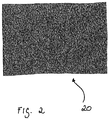
- Figure 2 shows a light micrograph of a section of a cerium, iron and titanium-containing magnetic material 20.
- the magnetic material 20 has the following composition: Fe 84.2 Ce 8.7 Ti 7.1 and is preferably with a tetragonal Ce (Fe, Ti) 12 Structure before.
- the composition was determined using EDX (energy-dispersive X-ray spectroscopy) and the crystal structure using X-ray spectroscopy.
- the magnetic material 20 was also obtained by mixing and melting the individual elements in the arc furnace. A hard magnetic phase was formed by heat treatment at 1050 ° C for 230 hours under argon. Magnetic material 20 also shows a Kerr pattern, but the termination domains are significantly narrower compared to the other magnetic material. This manifests itself in a lower anisotropy constant of approx. 2.5 MJ / m 3 and thus poorer magnetic characteristics. Due to the absence of cobalt, the thermal stability of the magnetic material 20 is also low.
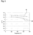
- Figure 3 is a diagram in which the saturation polarization J s of the magnetic materials from the Figures 1 and 2 are applied at different temperatures.
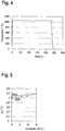
- FIG. 4 shows a diagram illustrating a first example of a heat treatment according to an advantageous embodiment of the invention.
- a complete treatment of a hard magnetic phase is ensured by a heat treatment, for example following the melting of the elements essential to the invention into a magnetic material, advantageously under protective gas.
- the melted material is cooled to 1050 ° C. in about 5 hours after cooling, held at about 1050 ° C.
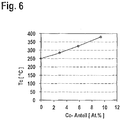
- Figures 5 and 6 show diagrams in which, on the one hand, the saturation polarization Js in Tesla of the magnetic material is plotted against the cobalt fraction in atomic percent (at.%) and, on the other hand, the Curie temperature Tc in ° C. is plotted against the cobalt fraction in atomic percent.
- the magnetic material had the following composition: 8 atom% of Ti, 8 atom% of Ce, Fe and Co, Fe serving as a balance and the amount of Co being varied.
- the magnetic material was made by mixing the respective elements and melting them in an arc.
- Figure 5 two curves can be seen, which were recorded at different temperatures (300 K and 400 K). Both curves show that the saturation polarization Js increases with increasing cobalt content. It can also be seen that the saturation polarization no longer drops as much at the higher temperature (400 K).
- the curve in Figure 6 shows that the Curie temperature Tc increases with increasing cobalt content. As a result, the magnetic material can be used particularly well in high-temperature applications.
Landscapes
- Chemical & Material Sciences (AREA)
- Engineering & Computer Science (AREA)
- Materials Engineering (AREA)
- Mechanical Engineering (AREA)
- Metallurgy (AREA)
- Organic Chemistry (AREA)
- Power Engineering (AREA)
- Crystallography & Structural Chemistry (AREA)
- Inorganic Chemistry (AREA)
- Manufacturing & Machinery (AREA)
- Physics & Mathematics (AREA)
- Electromagnetism (AREA)
- Hard Magnetic Materials (AREA)
- Powder Metallurgy (AREA)
- Manufacturing Cores, Coils, And Magnets (AREA)
Description
- Die vorliegende Erfindung betrifft ein Verfahren zur Herstellung eines magnetischen Materials.
- Durch den in jüngster Zeit vermehrten Einsatz von Elektromotoren, nicht zuletzt im Kraftfahrzeugbau, ist der Bedarf an hoch leistungsfähigen magnetischen Materialien, und insbesondere an Dauermagneten, in den letzten Jahren stark gestiegen. Geeignete magnetische Materialien umfassen hierbei solche mit hartmagnetischen Phasen, die sich durch eine hohe remanente Magnetisierung, ein großes Koerzitivfeld und ein großes Energieprodukt auszeichnen. Durch die hohe Leistungsdichte dieser magnetischen Materialien sind sie besonders gut für den Einsatz in bauraumreduzierten Vorrichtungen geeignet. Hochleistungsfähige, dauerhaft stabile und dabei kostenextensive magnetische Materialien sind damit Schlüsselkomponenten der Elektromobilität. Als besonders leistungsfähig, also ein großes Energieprodukt aufweisend, haben sich magnetische Materialien erwiesen, die mindestens ein Seltenerdmetall wie Neodym (Nd), Praseodym (Pr) und Samarium (Sm), sowie mindestens ein Übergangsmetall wie Eisen (Fe) oder Kobalt (Co) umfassen. Oftmals werden solche Materialien zur Optimierung der Gefügestruktur und damit auch der intrinsischen Magneteigenschaften mit interstitiellen Additiven, wie beispielsweise Bor (B), Kohlenstoff (C), Stickstoff (N) oder Wasserstoff (H), versetzt. Als besonders leistungsstarkes magnetisches Material hat sich Nd2Fe14B herausgestellt. Aufgrund seiner begrenzten chemischen, mechanischen und thermischen Langzeitstabilität, ist jedoch ein vollständiger Ersatz der herkömmlichen Ferrite durch Nd2Fe14B noch nicht erfolgt. Weiter nachteilig an Nd2Fe14B sind seine hohen Rohstoff- und Herstellkosten. Darüber hinaus ist die Verfügbarkeit von Seltenerdmetallen in so hohem Maße stark begrenzt, wodurch die Herstellmengen von Magneten auf Basis von hoch Seltenerdmetallhaltigen magnetischen Materialien, wie eben Nd2Fe14B, stark limitiert sind.
- Ein Beispiel eines magnetischen Materials findet sich in
EP 0 386 286 . Es offenbart, dass die Struktur des magnetischen Materials ein tetragonales RE(TM,Ti)12 mit einer ThMn12-Struktur ist. Weiterhin wird offenbart, dass das magnetische Material zumindest ein Seltenerdmetall enthält, wobei das Seltenerdmetall Ce und/oder La aufweist, dass das magnetischen Material als Übergangsmetall Kobalt umfasst, und dass das Übergangsmetall Fe enthält. - Das magnetische Material hergestellt gemäß dem Verfahren definiert im Anspruch 1 zeichnet sich durch ausgezeichnete magnetische Eigenschaften, und damit eine hohe remanente Magnetisierung, eine hohe Koerzitivfeldstärke, sowie ein großes Energieprodukt aus. Seine mechanische, magnetische, sowie thermische Stabilität ist hoch, was es für den Einsatz in stark beanspruchten, also beispielsweise beweglichen Vorrichtungen, wie Kraftfahrzeugen und mobilen elektronischen Geräten, prädestiniert. Durch die Verwendung mindestens eines Übergangsmetalls (TM), mindestens eines Seltenerdmetalls (RE) und Titan, wobei der Gehalt an Übergangsmetall 82 bis 86 Atom%, der Gehalt an Seltenerdmetall (RE) 7 bis 9 Atom% und der Gehalt an Titan 7 bis 9 Atom%, jeweils bezogen auf die Gesamtmasse des magnetischen Materials, beträgt, und wobei das Übergangsmetall Kobalt umfasst, wird ein hoch effizientes magnetisches Material erhalten, das sich durch besonders gute mechanische Eigenschaften, und insbesondere durch hervorragende magnetische Kennwerte, auszeichnet. Durch den spezifischen Gehalt an Titan wird zum einen das Gittergefüge des magnetischen Materials stabilisiert und zum anderen die Ausprägung der Anisotropie gefördert. Ferner wurde gefunden, dass Kobalt, gerade in der o.g. Kombination mit Titan einen wesentlichen Beitrag zur Verbesserung der magnetischen Kennwerte des magnetischen Materials beiträgt. Durch Kombination eines Übergangsmetalls, eines Seltenerdmetalls und Titan mit Kobalt wird die Anisotropiekonstante und Sättigungspolarisation erhöht. Dies bedeutet, dass durch die Elementkombination sowohl die Stärke des magnetischen Materials als auch dessen Entmagnetisierfestigkeit, also seine Koerzitivfeldstärke, und damit die Leistungsdichte des magnetischen Materials verbessert werden. Ferner kann hierdurch der Gehalt an Seltenerdmetall effektiv reduziert werden, was die Rohstoffkosten des magnetischen Materials senkt und eine hohe Verfügbarkeit der Rohstoffe sichert. So kann Versorgungsengpässe vorgebeugt und eine Limitierung der Herstellmengen umgangen werden. Zudem wird durch den Zusatz von Kobalt die Curie-Temperatur des magnetischen Materials deutlich angehoben, was die Anwendung des magnetischen Materials besonders dort fördert, wo sehr hohe Temperaturen auftreten, wie beispielsweise in Elektromotoren und Generatoren. Durch Verwendung des erfindungsgemäßen magnetischen Materials eröffnen sich folglich vielfache Anwendungsmöglichkeiten auch in Niedrigpreisprodukten, ohne deren qualitative Eigenschaften nachteilig zu beeinflussen. Die Unteransprüche zeigen bevorzugte Weiterbildungen der Erfindung.
- Gemäß der Erfindung umfasst das Übergangsmetall Kobalt mit einem Gehalt von 8 bis 20 Atom%, bezogen auf den Gesamtgehalt in Atom% an Übergangsmetall. Hierdurch wird ein optimaler Kompromiss zwischen sehr guten magnetischen Eigenschaften und moderater Kostenstruktur des magnetischen Materials erzielt.
- Das Übergangsmetall enthält Eisen. Eisen bildet mit Seltenerdmetallen, Titan und Kobalt besonders stabile Gitterstrukturen und tragen verstärkt zur Ausprägung der gewünschten vorteilhaften magnetischen Eigenschaften, also insbesondere zur Sättigung und Erhöhung der magnetischen Anisotropie des erfindungsgemäßen Materials, bei. Ferner ist ihre Verfügbarkeit am Markt bei relativ niedrigen Rohstoffkosten hoch, was die Materialkosten des erfindungsgemäßen magnetischen Materials deutlich reduziert. Die unter diesen Metallen bevorzugte Verwendung von Fe ist auf seine gesundheitliche, sowie ökologische Unbedenklichkeit und darüber hinaus auch auf seine im Vergleich zu Ni und Mn noch einmal deutlich reduzierten Rohstoffkosten zurückzuführen.
- Es ist vorgesehen, dass das Seltenerdmetall Ce und/oder La ist. Die angeführten Seltenerdmetalle La und Ce haben sich als besonders gut kompatibel mit den übrigen erfindungswesentlichen Komponenten erwiesen, und fördern ihrerseits die Bildung dauerhaft stabiler Kristallgitterstrukturen mit hoher Anisotropie, wodurch die magnetischen Eigenschaften des magnetischen Materials verbessert werden. Aufgrund der besonders hohen Verfügbarkeit und relativ niedrigen Rohstoffkosten ist die Verwendung der Elemente La und Ce vorgesehen.
- Weiter beträgt der Gehalt an Übergangsmetall 82 bis 86 Atom%, der Gehalt an Seltenerdmetall 7 bis 9 Atom% und der Gehalt an Titan 7 bis 9 Atom%, jeweils bezogen auf die Gesamtmasse des magnetischen Materials. Hierdurch werden die Leistungsdichte und die mechanischen Eigenschaften des erfindungsgemäßen magnetischen Materials verbessert. Insbesondere werden somit die remanente Magnetisierung und die Koerzitivfeldstärke des erfindungsgemäßen magnetischen Materials bei reduziertem Gehalt an Seltenerdmetall, und damit optimierter Kostenstruktur, maximiert.
- Die Struktur des magnetischen Materials ist tetragonales RE(TM,Ti)12' was sich aufgrund der vorteilhaften Elektronenstruktur und Elektronenkonfiguration, sowie der Spin- und Bahnmomente der Atome positiv auf die Ausbildung anisotroper Phasen des magnetischen Materials auswirkt.
- Weiter wird auch ein Dauermagnet beschrieben, der ein wie oben beschriebenes magnetisches Material umfasst. Das Material liegt in dem Dauermagneten als hartmagnetische Phase vor. Der Dauermagnet kann neben dem magnetischen Material weitere magnetische oder nichtmagnetische Phasen aufweisen, kann aber auch nur aus dem magnetischen Material bestehen. Der Dauermagnet kann beispielsweise kunststoffgebunden sein.
- Die für das magnetische Material beschriebenen vorteilhaften Effekte, Vorteile und Weiterbildungen finden auch Anwendung auf den Dauermagneten.
- Erfindungsgemäß wird auch ein Verfahren zum Herstellen eines magnetischen Materials beschrieben, wobei das Verfahren durch die Schritte des Mischens mindestens eines Übergangsmetalls (TM), mindestens eines Seltenerdmetalls (RE) und Titan, wobei der Gehalt an Übergangsmetall 82 bis 86 Atom%, der Gehalt an Seltenerdmetall 7 bis 9 Atom% und der Gehalt an Titan 7 bis 9 Atom%, jeweils bezogen auf die Gesamtmasse des magnetischen Materials, beträgt und wobei das Übergangsmetall Kobalt umfasst und des Schmelzens der erhaltenen Mischung, gekennzeichnet ist. Das Übergangsmetall enthält auch Eisen. Durch das erfindungsgemäße Verfahren wird auf einfache und kostengünstige Weise ein magnetisches Material mit hoher Leistungsdichte, einer ausgezeichneten remanenten Magnetisierung und Koerzitivfeldstärke, sowie großem Energieprodukt bereitgestellt, das ferner eine sehr gute mechanische Stabilität aufweist.
- Das Schmelzen der Mischung aus den erfindungswesentlichen Elementen kann beispielsweise im Lichtbogen oder im Vakuumofen erfolgen. Durch diese Verfahrensführung wird gewährleistet, dass alle Elemente vollständig aufgeschmolzen werden, ohne dass es dabei zu Oxidation des Materials kommt, so dass ein homogenes Kristallgefüge gebildet wird, was nicht nur die mechanische Stabilität des sich bildenden magnetischen Materials vorteilhaft beeinflusst, sondern in erheblichem Maße auch die gewünschten magnetischen Eigenschaften prägt.
- Die für das magnetische Material beschriebenen vorteilhaften Eigenschaften, Effekte und Weiterbildungen finden auch Anwendung auf das erfindungsgemäße Verfahren zum Herstellen eines solchen magnetischen Materials. Ferner sei ausgeführt, dass sich das oben beschriebene magnetische Material durch das erfindungsgemäße Verfahren herstellen lässt.
- Entsprechend der vorliegenden Erfindung erfolgt in einem sich an das Schmelzen anschließenden Schritt eine Wärmebehandlung bei einer Temperatur zwischen 500 °C und 1500 °C vorzugsweise zwischen 700 °C und 1100 °C, für eine Dauer von 5 bis 12 Tage. Durch diese Wärmebehandlung, die vorzugsweise unter Schutzgasatmosphäre, und insbesondere unter Argon, ausgeführt wird, wird die vollständige Ausbildung des magnetischen Materials, erfindungsgemäß als hartmagnetische Phase, begünstigt.
- Gemäß einer weiteren vorteilhaften Ausführungsform des erfindungsgemäßen Verfahrens wird die erhaltene Mischung nach dem Schmelzen oder nach erfolgter Wärmebehandlung in einem sich anschließenden Schritt gemahlen und/oder einer Nitridierung unterzogen. Das Mahlen der erhaltenen Mischung fördert seine weitere Verarbeitbarkeit, beispielsweise zu einem gesinterten magnetischen Material. Durch eine Nitridierung können die magnetischen Eigenschaften des Materials, und insbesondere seine Anisotropie, verbessert werden. Besonders vorteilhaft wird die erhaltene Mischung zunächst gemahlen und anschließend nitridiert, da auf diese Weise eine gleichmäßige Nitridierung auch bis ins feinste Korn erzielt werden kann, wodurch die magnetischen Eigenschaften des resultierenden Materials besonders stark verbessert werden.
- Die vorliegende Erfindung erzeugt auch einen kunststoffgebundenen Magnet, der ein wie vorstehend beschriebenes magnetisches Material oder ein durch das vorstehend beschriebene Verfahren hergestelltes magnetisches Material enthält. Das magnetische Material kann dabei auch mittels Rascherstarrung (meltspinning) hergestellt sein.
- Weiter wird auch die Verwendung eines wie oben ausgeführten magnetischen Materials vorzugsweise in Windkraftanlagen, PKW, NKW, Startern, Elektromotoren, Lautsprechern und mikroelektromechanischen Systemen, beschrieben. Aufgrund der herausragenden magnetischen Eigenschaften des magnetischen Materials, sowie seiner ausgezeichneten Stabilität, und damit auch seiner vorteilhaften Einsatzfähigkeit in bauraumreduzierten Anwendungen und Anwendungen unter hohen Temperaturen, ist die Verwendung in den genannten Vorrichtungen von besonderem Vorteil.
- Weiter wird eine elektrische Maschine beschrieben, insbesondere ein Generator, Kraftfahrzeug, Starter, Elektromotor, Lautsprecher oder mikroelektromechanisches System beschrieben, die das magnetische Material oder mindestens einen Dauermagnet oder ein magnetisches Material, das nach dem vorstehenden erfindungsgemäßen Verfahren hergestellt wurde, enthält. Die elektrische Maschine weist sehr gute magnetische Eigenschaften und eine hohe thermische Stabilität bei moderater Kostenstruktur auf.
- Die für das magnetische Material, sowie das erfindungsgemäße Verfahren beschriebenen Vorteile, vorteilhaften Effekte und bevorzugten Weiterbildungen finden auch Anwendung auf den kunststoffgebundenen Magnet sowie die elektrische Maschine.
- Nachfolgend werden Ausführungsbeispiele der Erfindung unter Bezugnahme auf die begleitende Zeichnung im Detail beschrieben. In der Zeichnung ist:
- Figur 1
- eine lichtmikroskopische Aufnahme eines Schliffes des magnetischen Materials gemäß einer vorteilhaften Weiterbildung im polarisierten Licht,
- Figur 2
- eine lichtmikroskopische Aufnahme eines Schliffes eines Cer-, Eisen- und Titanhaltigen magnetischen Materials im polarisierten Licht,
- Figur 3
- ein Diagramm, in dem die Sättigungspolarisation Js der magnetischen Materialien aus den
Figuren 1 und2 bei unterschiedlichen Temperaturen aufgetragen sind, - Figur 4
- ein Diagramm, das ein erstes Beispiel für eine Wärmebehandlung gemäß einer vorteilhaften Weiterbildung der Erfindung darstellt,
- Figur 5
- ein Diagramm, in dem die Sättigungspolarisation Js eines magnetischen Materials gemäß einer ersten vorteilhaften Weiterbildung der Erfindung gegen den Kobaltanteil aufgetragen ist und
- Figur 6
- ein Diagramm, in dem die Curie-Temperatur Tc eines magnetischen Materials gemäß einer ersten vorteilhaften Weiterbildung der Erfindung gegen den Kobaltanteil aufgetragen ist.
-
Figur 1 zeigt eine lichtmikroskopische Aufnahme eines Schliffes des magnetischen Materials 10 im polarisierten Licht. Das Material 10 hat folgende Zusammensetzung: Fe64Co2,6Ce8,0Ti8,0 und liegt vorzugsweise mit einer überwiegend tetragonalen Ce(Fe/Co,Ti)12 (ThMn12-) Struktur vor. Die Zusammensetzung wurde mittels EDX (Energiedispersiver Röntgenspektroskopie) und die Kristallstruktur mittels Röntgenspektroskopie bestimmt. - Das magnetische Material 10 wurde durch Mischen und Schmelzen der einzelnen Elemente im Lichtbogenofen erhalten. Durch Temperaturbehandlung bei 1050 °C für 230 Stunden unter Argon, bildete sich eine hartmagnetische Phase aus.
- Das magnetische Material 10 aus
Figur 1 liegt somit als hartmagnetische Phase vor, was an dem so genannten Kerr-Muster, also einem - je nach Betrachtungswinkel rosettenartigen oder streifigen Muster, zu erkennen ist, das das Vorhandensein einer starken hartmagnetischen Phase aus Ce(Fe/Co,Ti)12 anzeigt. Die Abschlussdomänen sind relativ breit, was sich in einer hohen Anisotropiekonstante K1 von ca. 3,0 MJ/m3 widerspiegelt. Die Anisotropiekonstante K1 kann wie in folgender Literatur beschrieben, ermittelt werden: R. Bodenberger, A. Hubert, Phys. Stat. Sol. (a) 44, K7-K11 (1977). Das magnetische Material 10 zeichnet sich somit durch ein großes Energieprodukt, eine hohe Curie-Temperatur, eine hohe Koerzitivfeldstärke, hohe remanente Magnetisierung, sowie gute, durch die homogene Kristallstruktur bedingte, mechanische Eigenschaften aus.
Figur 2 zeigt eine lichtmikroskopische Aufnahme eines Schliffes eines Cer, Eisen und Titan haltigen magnetischen Materials 20. Das magnetische Material 20 hat folgende Zusammensetzung: Fe84,2Ce8,7Ti7,1 und liegt vorzugsweise mit einer tetragonalen Ce(Fe,Ti)12 Struktur vor. Die Zusammensetzung wurde mittels EDX (Energiedispersiver Röntgenspektroskopie) und die Kristallstruktur mittels Röntgenspektroskopie bestimmt. - Das magnetische Material 20 wurde ebenfalls durch Mischen und Schmelzen der einzelnen Elemente im Lichtbogenofen erhalten. Durch Temperaturbehandlung bei 1050 °C für 230 Stunden unter Argon, bildete sich eine hartmagnetische Phase aus.
Das magnetische Material 20 zeigt ebenfalls ein Kerr-Muster, jedoch sind die Abschlussdomänen im Vergleich zu dem anderen magnetischen Material deutlich schmaler. Dies äußert sich in einer niedrigeren Anisotropiekonstante von ca. 2.5 MJ/m3 und damit schlechteren magnetischen Kennwerten. Durch die Abwesenheit von Kobalt ist zudem die thermische Stabilität des magnetischen Materials 20 gering.
Figur 3 ist ein Diagramm, in dem die Sättigungspolarisation Js der magnetischen Materialien aus denFiguren 1 und2 bei unterschiedlichen Temperaturen aufgetragen sind. Deutlich erkennbar ist, dass die Sättigungspolarisation des magnetischen Materials 10 gegenüber dem Material 20 durch die Zugabe von Kobalt ansteigt, wodurch auch die Temperaturstabilität verbessert wird. Entsprechend nimmt auch die Curie-Temperatur durch die Zugabe von Kobalt zu, was vor allen Dingen für Anwendungen, in denen hohe Temperaturen vorherrschen, wie z.B. in einem Elektromotor, wichtig ist.
Figur 4 zeigt ein Diagramm, das ein erstes Beispiel für eine Wärmebehandlung gemäß einer vorteilhaften Ausführungsform der Erfindung darstellt. Wie bereits ausgeführt, wird durch eine sich beispielsweise an das Schmelzen der erfindungswesentlichen Elemente zu einem magnetischen Material anschließende Wärmebehandlung, vorteilhafterweise unter Schutzgas, die vollständige Ausprägung einer hartmagnetischen Phase sichergestellt. In einem ersten Schritt wird hierzu das aufgeschmolzene Material nach Abkühlung innerhalb von etwa 5 Stunden im Vakuumofen auf 1050 °C erhitzt, für etwa 235 Stunde auf etwa 1050 °C gehalten, dann innerhalb von etwa 5 Stunden auf Raumtemperatur (etwa 20 °C) abgekühlt. Hierdurch wird ein magnetisches Material mit exzellenten magnetischen Eigenschaften, also ein magnetisches Material mit einer vollständig ausgeprägten hartmagnetischen Phase, das insbesondere aus Hartmagnetkörnern besteht, gebildet, das sich ferner durch hervorragende mechanische und thermische Stabilität auszeichnet. -
Figuren 5 und6 zeigen Diagramme, in denen zum einen die Sättigungspolarisation Js in Tesla des magnetischen Materials gegen den Kobaltanteil in Atomprozent (At.%) und zum anderen die Curie-Temperatur Tc in °C gegen den Kobaltanteil in Atomprozent aufgetragen ist. Das magnetische Material hatte folgende Zusammensetzung: 8 Atom-% Ti, 8 Atom-% Ce, Fe und Co, wobei Fe als Ausgleich diente und die Menge an Co variiert wurde. Das magnetische Material wurde durch Mischen der jeweiligen Elemente und Schmelzen derselben im Lichtbogen hergestellt.
Im Detail sindFigur 5 zwei Kurven zu entnehmen, die bei unterschiedlichen Temperaturen (300 K und 400 K) aufgenommen wurden. Beide Kurven zeigen, dass die Sättigungspolarisation Js mit steigendem Kobaltanteil zunimmt. Ferner ist zu erkennen, dass die Sättigungspolarisation bei der höheren Temperatur (400 K) nicht mehr so stark abfällt. - Die Kurve in
Figur 6 zeigt, dass mit zunehmendem Kobaltanteil die Curie-Temperatur Tc ansteigt. Dadurch kann das magnetische Material besonderes gut in Hochtemperaturanwendungen verwendet werden.
Claims (3)
- Verfahren zum Herstellen eines magnetischen Materials, wobei eine Struktur des magnetischen Materials tetragonales RE(TM,Ti)12 mit einer ThMn12-Struktur ist, durch- Mischen mindestens eines Übergangsmetalls (TM), mindestens eines Seltenerdmetalls (RE) und Titan, wobei der Gehalt an Übergangsmetall 82 bis 86 Atom%, der Gehalt an Seltenerdmetall 7 bis 9 Atom% und der Gehalt an Titan 7 bis 9 Atom%, jeweils bezogen auf die Gesamtmasse des magnetischen Materials, beträgt und wobei das Übergangsmetall Kobalt mit einem Gehalt von 8 bis 20 Atom%, bezogen auf den Gesamtgehalt in Atom% an Übergangsmetall, umfasst, wobei das Übergangsmetall Fe enthält, und das Seltenerdmetall Ce und/oder La ist, und das magnetische Material eine starke hartmagnetisch Phase aus Ce(Fe/Co, Ti)12 und/oder La(Fe/Co, Ti)12 aufweist. und- Schmelzen der erhaltenen Mischung bis ein homogenes Gemisch entsteht, und, dass in einem sich an das Schmelzen anschließenden Schritt eine Wärmebehandlung bei einer Temperatur zwischen 500 °C und 1500 °C, für eine Dauer von 5 bis 12 Tage, erfolgt.
- Verfahren nach Anspruch 1, dadurch gekennzeichnet, dass die Wärmebehandlung bei einer Temperatur zwischen 700 °C und 1100 °C erfolgt.
- Verfahren nach einem der Ansprüche 1 oder 2, dadurch gekennzeichnet, dass die erhaltene Mischung in einem weiteren Schritt gemahlen und/oder einer Nitridierung unterzogen wird.
Applications Claiming Priority (2)
| Application Number | Priority Date | Filing Date | Title |
|---|---|---|---|
| DE102013009940.4A DE102013009940A1 (de) | 2013-06-13 | 2013-06-13 | Magnetisches Material, seine Verwendung und Verfahren zu dessen Herstellung |
| PCT/EP2014/062001 WO2014198708A1 (de) | 2013-06-13 | 2014-06-10 | Magnetisches material, seine verwendung und verfahren zu dessen herstellung |
Publications (2)
| Publication Number | Publication Date |
|---|---|
| EP3008221A1 EP3008221A1 (de) | 2016-04-20 |
| EP3008221B1 true EP3008221B1 (de) | 2020-03-04 |
Family
ID=50896318
Family Applications (1)
| Application Number | Title | Priority Date | Filing Date |
|---|---|---|---|
| EP14728593.6A Active EP3008221B1 (de) | 2013-06-13 | 2014-06-10 | Magnetisches material, seine verwendung und verfahren zu dessen herstellung |
Country Status (6)
| Country | Link |
|---|---|
| US (1) | US20160148734A1 (de) |
| EP (1) | EP3008221B1 (de) |
| JP (1) | JP2016528717A (de) |
| CN (1) | CN105555980A (de) |
| DE (1) | DE102013009940A1 (de) |
| WO (1) | WO2014198708A1 (de) |
Families Citing this family (9)
| Publication number | Priority date | Publication date | Assignee | Title |
|---|---|---|---|---|
| US10062482B2 (en) * | 2015-08-25 | 2018-08-28 | GM Global Technology Operations LLC | Rapid consolidation method for preparing bulk metastable iron-rich materials |
| EP3291250B1 (de) | 2016-08-24 | 2021-05-26 | Kabushiki Kaisha Toshiba | Magnetmaterial, dauermagnet, elektrische rotationsmaschine und fahrzeug |
| CN107785139A (zh) | 2016-08-24 | 2018-03-09 | 株式会社东芝 | 磁铁材料、永久磁铁、旋转电机及车辆 |
| US10490325B2 (en) | 2016-08-24 | 2019-11-26 | Kabushiki Kaisha Toshiba | Magnetic material, permanent magnet, rotary electrical machine, and vehicle |
| CN109952621B (zh) * | 2016-12-26 | 2021-01-26 | 日立金属株式会社 | 稀土-过渡金属系强磁性合金 |
| CN107385343B (zh) * | 2017-07-21 | 2020-02-28 | 张栗珲 | 一种量子水处理器及用于水处理的功能材料 |
| JP6733871B2 (ja) * | 2017-08-22 | 2020-08-05 | トヨタ自動車株式会社 | 磁性化合物及びその製造方法 |
| JP6995542B2 (ja) * | 2017-09-19 | 2022-02-04 | 株式会社東芝 | 磁石材料、永久磁石、回転電機、及び車両 |
| CN111655891B (zh) * | 2018-01-30 | 2022-04-05 | Tdk株式会社 | 永久磁铁 |
Family Cites Families (14)
| Publication number | Priority date | Publication date | Assignee | Title |
|---|---|---|---|---|
| US500A (en) * | 1837-12-01 | Improved excavating-machine | ||
| EP0242283B1 (de) * | 1986-04-12 | 1990-11-07 | Shin-Etsu Chemical Co., Ltd. | Legierung auf Basis seltener Erden für Permanentmagnet |
| EP0386286B1 (de) * | 1987-09-17 | 1995-10-18 | Shin-Etsu Chemical Co., Ltd. | Auf Seltenerdeisen basierender Dauermagnet |
| JP3057448B2 (ja) * | 1988-05-26 | 2000-06-26 | 信越化学工業株式会社 | 希土類永久磁石 |
| DE4133214C2 (de) * | 1990-10-05 | 1996-11-07 | Hitachi Metals Ltd | Aus Eisen-Seltenerdmetall-Legierung bestehendes Dauermagnetmaterial |
| JPH05230502A (ja) * | 1992-02-21 | 1993-09-07 | Minebea Co Ltd | 希土類ボンド磁石の製造方法 |
| JPH06192795A (ja) * | 1992-12-25 | 1994-07-12 | Hitachi Metals Ltd | 永久磁石合金 |
| US5456769A (en) * | 1993-03-10 | 1995-10-10 | Kabushiki Kaisha Toshiba | Magnetic material |
| JPH07126816A (ja) * | 1993-11-02 | 1995-05-16 | Tokin Corp | 希土類永久磁石材料 |
| JPH07161515A (ja) * | 1993-12-06 | 1995-06-23 | Tokin Corp | 希土類永久磁石材料 |
| JPH116038A (ja) * | 1997-06-16 | 1999-01-12 | Tokin Corp | 希土類永久磁石材料 |
| US7186303B2 (en) * | 2002-08-21 | 2007-03-06 | Neomax Co., Ltd. | Magnetic alloy material and method of making the magnetic alloy material |
| DE102005001198A1 (de) * | 2005-01-10 | 2006-07-20 | H.C. Starck Gmbh | Metallische Pulvermischungen |
| US9548150B2 (en) * | 2013-03-06 | 2017-01-17 | GM Global Technology Operations LLC | Cerium-iron-based magnetic compounds |
-
2013
- 2013-06-13 DE DE102013009940.4A patent/DE102013009940A1/de not_active Withdrawn
-
2014
- 2014-06-10 US US14/898,478 patent/US20160148734A1/en not_active Abandoned
- 2014-06-10 WO PCT/EP2014/062001 patent/WO2014198708A1/de not_active Ceased
- 2014-06-10 JP JP2016518971A patent/JP2016528717A/ja active Pending
- 2014-06-10 EP EP14728593.6A patent/EP3008221B1/de active Active
- 2014-06-10 CN CN201480033127.1A patent/CN105555980A/zh active Pending
Non-Patent Citations (1)
| Title |
|---|
| None * |
Also Published As
| Publication number | Publication date |
|---|---|
| US20160148734A1 (en) | 2016-05-26 |
| EP3008221A1 (de) | 2016-04-20 |
| DE102013009940A1 (de) | 2014-12-18 |
| JP2016528717A (ja) | 2016-09-15 |
| WO2014198708A1 (de) | 2014-12-18 |
| CN105555980A (zh) | 2016-05-04 |
Similar Documents
| Publication | Publication Date | Title |
|---|---|---|
| DE102013009940A1 (de) | Magnetisches Material, seine Verwendung und Verfahren zu dessen Herstellung | |
| DE60036586T2 (de) | Hartmagnetisches interstitielles Material mit mehreren Elementen und Herstellungsverfahren eines magnetischen Pulvers und Magnet daraus | |
| DE112013007128B4 (de) | Herstellungsverfahren für ein Seltenerd-Permanentmagnetpulver | |
| DE3789951T2 (de) | Anisotropes Magnetpulver, Magnet daraus und Herstellungsverfahren. | |
| DE102016122327A1 (de) | Seltenerdmagnet | |
| DE102011052611A1 (de) | Arbeitskomponente für einen magnetischen Wärmeaustausch und Verfahren zur Erzeugung einer Arbeitskomponente für eine magnetische Kühlung | |
| DE102013200651A1 (de) | Permanentmagnet und Motor und Stromerzeuger unter dessen Verwendung | |
| DE102015115217A1 (de) | Hochtemperatur-Hybridpermanentmagnet | |
| DE102013201492A1 (de) | Permanentmagnet und Motor und Generator, die diesen verwenden | |
| DE69212569T2 (de) | Verfahren zur Herstellung von Legierungspulvern des SE-Fe/Co-B-M-Typs und gebundene Magnete mit diesem Legierungspulver | |
| DE4408114B4 (de) | Magnetisches Material | |
| EP2422347B1 (de) | Magnetisches legierungsmaterial und verfahren zu seiner herstellung | |
| DE102014223991A1 (de) | Magnetisches Material, Verfahren zu dessen Herstellung und elektrische Maschine mit einem magnetischen Material | |
| WO2013164202A1 (de) | Magnetisches material, seine verwendung und verfahren zu dessen herstellung | |
| DE102013201370A1 (de) | Permanentmagnet und Motor und Stromgenerator, der diesen verwendet | |
| DE4133214C2 (de) | Aus Eisen-Seltenerdmetall-Legierung bestehendes Dauermagnetmaterial | |
| WO2014079822A2 (de) | Magnetisches material und verfahren zu dessen herstellung | |
| DE102020128947A1 (de) | Verfahren zur herstellung eines anisotropen magnetpulvers aus seltenerdelement | |
| DE69118577T2 (de) | Seltenerd-basierte magnetische Materialien, Herstellungsverfahren und Anwendung | |
| WO2014009057A1 (de) | Magnetisches material, seine verwendung und verfahren zu dessen herstellung | |
| DE102018114722A1 (de) | Herstellung eines mnbi ltp-magneten durch direktsintern | |
| DE2507105C2 (de) | Verfahren zur Herstellung von permanentmagnetischem Material, enthaltend Samarium, Kobalt, Kupfer und gegebenenfalls Eisen | |
| DE102020113223A1 (de) | Gesinterter r2m17-magnet und verfahren zur herstellung eines r2m17-magneten | |
| DE102006032520B4 (de) | Verfahren zur Herstellung von Magnetkernen, Magnetkern und induktives Bauelement mit einem Magnetkern | |
| DE102015218560A1 (de) | Hartmagnetphase, Verfahren zu ihrer Herstellung und magnetisches Material |
Legal Events
| Date | Code | Title | Description |
|---|---|---|---|
| PUAI | Public reference made under article 153(3) epc to a published international application that has entered the european phase |
Free format text: ORIGINAL CODE: 0009012 |
|
| 17P | Request for examination filed |
Effective date: 20160113 |
|
| AK | Designated contracting states |
Kind code of ref document: A1 Designated state(s): AL AT BE BG CH CY CZ DE DK EE ES FI FR GB GR HR HU IE IS IT LI LT LU LV MC MK MT NL NO PL PT RO RS SE SI SK SM TR |
|
| AX | Request for extension of the european patent |
Extension state: BA ME |
|
| DAX | Request for extension of the european patent (deleted) | ||
| STAA | Information on the status of an ep patent application or granted ep patent |
Free format text: STATUS: EXAMINATION IS IN PROGRESS |
|
| 17Q | First examination report despatched |
Effective date: 20171222 |
|
| GRAP | Despatch of communication of intention to grant a patent |
Free format text: ORIGINAL CODE: EPIDOSNIGR1 |
|
| STAA | Information on the status of an ep patent application or granted ep patent |
Free format text: STATUS: GRANT OF PATENT IS INTENDED |
|
| INTG | Intention to grant announced |
Effective date: 20191204 |
|
| GRAS | Grant fee paid |
Free format text: ORIGINAL CODE: EPIDOSNIGR3 |
|
| GRAA | (expected) grant |
Free format text: ORIGINAL CODE: 0009210 |
|
| STAA | Information on the status of an ep patent application or granted ep patent |
Free format text: STATUS: THE PATENT HAS BEEN GRANTED |
|
| AK | Designated contracting states |
Kind code of ref document: B1 Designated state(s): AL AT BE BG CH CY CZ DE DK EE ES FI FR GB GR HR HU IE IS IT LI LT LU LV MC MK MT NL NO PL PT RO RS SE SI SK SM TR |
|
| REG | Reference to a national code |
Ref country code: GB Ref legal event code: FG4D Free format text: NOT ENGLISH |
|
| REG | Reference to a national code |
Ref country code: CH Ref legal event code: EP |
|
| REG | Reference to a national code |
Ref country code: AT Ref legal event code: REF Ref document number: 1240429 Country of ref document: AT Kind code of ref document: T Effective date: 20200315 |
|
| REG | Reference to a national code |
Ref country code: DE Ref legal event code: R096 Ref document number: 502014013749 Country of ref document: DE |
|
| REG | Reference to a national code |
Ref country code: IE Ref legal event code: FG4D Free format text: LANGUAGE OF EP DOCUMENT: GERMAN |
|
| RAP2 | Party data changed (patent owner data changed or rights of a patent transferred) |
Owner name: ROBERT BOSCH GMBH |
|
| PG25 | Lapsed in a contracting state [announced via postgrant information from national office to epo] |
Ref country code: FI Free format text: LAPSE BECAUSE OF FAILURE TO SUBMIT A TRANSLATION OF THE DESCRIPTION OR TO PAY THE FEE WITHIN THE PRESCRIBED TIME-LIMIT Effective date: 20200304 Ref country code: NO Free format text: LAPSE BECAUSE OF FAILURE TO SUBMIT A TRANSLATION OF THE DESCRIPTION OR TO PAY THE FEE WITHIN THE PRESCRIBED TIME-LIMIT Effective date: 20200604 Ref country code: RS Free format text: LAPSE BECAUSE OF FAILURE TO SUBMIT A TRANSLATION OF THE DESCRIPTION OR TO PAY THE FEE WITHIN THE PRESCRIBED TIME-LIMIT Effective date: 20200304 |
|
| REG | Reference to a national code |
Ref country code: NL Ref legal event code: MP Effective date: 20200304 |
|
| PG25 | Lapsed in a contracting state [announced via postgrant information from national office to epo] |
Ref country code: SE Free format text: LAPSE BECAUSE OF FAILURE TO SUBMIT A TRANSLATION OF THE DESCRIPTION OR TO PAY THE FEE WITHIN THE PRESCRIBED TIME-LIMIT Effective date: 20200304 Ref country code: LV Free format text: LAPSE BECAUSE OF FAILURE TO SUBMIT A TRANSLATION OF THE DESCRIPTION OR TO PAY THE FEE WITHIN THE PRESCRIBED TIME-LIMIT Effective date: 20200304 Ref country code: HR Free format text: LAPSE BECAUSE OF FAILURE TO SUBMIT A TRANSLATION OF THE DESCRIPTION OR TO PAY THE FEE WITHIN THE PRESCRIBED TIME-LIMIT Effective date: 20200304 Ref country code: GR Free format text: LAPSE BECAUSE OF FAILURE TO SUBMIT A TRANSLATION OF THE DESCRIPTION OR TO PAY THE FEE WITHIN THE PRESCRIBED TIME-LIMIT Effective date: 20200605 Ref country code: BG Free format text: LAPSE BECAUSE OF FAILURE TO SUBMIT A TRANSLATION OF THE DESCRIPTION OR TO PAY THE FEE WITHIN THE PRESCRIBED TIME-LIMIT Effective date: 20200604 |
|
| REG | Reference to a national code |
Ref country code: LT Ref legal event code: MG4D |
|
| PG25 | Lapsed in a contracting state [announced via postgrant information from national office to epo] |
Ref country code: NL Free format text: LAPSE BECAUSE OF FAILURE TO SUBMIT A TRANSLATION OF THE DESCRIPTION OR TO PAY THE FEE WITHIN THE PRESCRIBED TIME-LIMIT Effective date: 20200304 |
|
| PG25 | Lapsed in a contracting state [announced via postgrant information from national office to epo] |
Ref country code: SM Free format text: LAPSE BECAUSE OF FAILURE TO SUBMIT A TRANSLATION OF THE DESCRIPTION OR TO PAY THE FEE WITHIN THE PRESCRIBED TIME-LIMIT Effective date: 20200304 Ref country code: LT Free format text: LAPSE BECAUSE OF FAILURE TO SUBMIT A TRANSLATION OF THE DESCRIPTION OR TO PAY THE FEE WITHIN THE PRESCRIBED TIME-LIMIT Effective date: 20200304 Ref country code: EE Free format text: LAPSE BECAUSE OF FAILURE TO SUBMIT A TRANSLATION OF THE DESCRIPTION OR TO PAY THE FEE WITHIN THE PRESCRIBED TIME-LIMIT Effective date: 20200304 Ref country code: RO Free format text: LAPSE BECAUSE OF FAILURE TO SUBMIT A TRANSLATION OF THE DESCRIPTION OR TO PAY THE FEE WITHIN THE PRESCRIBED TIME-LIMIT Effective date: 20200304 Ref country code: CZ Free format text: LAPSE BECAUSE OF FAILURE TO SUBMIT A TRANSLATION OF THE DESCRIPTION OR TO PAY THE FEE WITHIN THE PRESCRIBED TIME-LIMIT Effective date: 20200304 Ref country code: ES Free format text: LAPSE BECAUSE OF FAILURE TO SUBMIT A TRANSLATION OF THE DESCRIPTION OR TO PAY THE FEE WITHIN THE PRESCRIBED TIME-LIMIT Effective date: 20200304 Ref country code: PT Free format text: LAPSE BECAUSE OF FAILURE TO SUBMIT A TRANSLATION OF THE DESCRIPTION OR TO PAY THE FEE WITHIN THE PRESCRIBED TIME-LIMIT Effective date: 20200729 Ref country code: IS Free format text: LAPSE BECAUSE OF FAILURE TO SUBMIT A TRANSLATION OF THE DESCRIPTION OR TO PAY THE FEE WITHIN THE PRESCRIBED TIME-LIMIT Effective date: 20200704 Ref country code: SK Free format text: LAPSE BECAUSE OF FAILURE TO SUBMIT A TRANSLATION OF THE DESCRIPTION OR TO PAY THE FEE WITHIN THE PRESCRIBED TIME-LIMIT Effective date: 20200304 |
|
| REG | Reference to a national code |
Ref country code: DE Ref legal event code: R097 Ref document number: 502014013749 Country of ref document: DE |
|
| PLBE | No opposition filed within time limit |
Free format text: ORIGINAL CODE: 0009261 |
|
| STAA | Information on the status of an ep patent application or granted ep patent |
Free format text: STATUS: NO OPPOSITION FILED WITHIN TIME LIMIT |
|
| PG25 | Lapsed in a contracting state [announced via postgrant information from national office to epo] |
Ref country code: MC Free format text: LAPSE BECAUSE OF FAILURE TO SUBMIT A TRANSLATION OF THE DESCRIPTION OR TO PAY THE FEE WITHIN THE PRESCRIBED TIME-LIMIT Effective date: 20200304 Ref country code: IT Free format text: LAPSE BECAUSE OF FAILURE TO SUBMIT A TRANSLATION OF THE DESCRIPTION OR TO PAY THE FEE WITHIN THE PRESCRIBED TIME-LIMIT Effective date: 20200304 Ref country code: DK Free format text: LAPSE BECAUSE OF FAILURE TO SUBMIT A TRANSLATION OF THE DESCRIPTION OR TO PAY THE FEE WITHIN THE PRESCRIBED TIME-LIMIT Effective date: 20200304 |
|
| REG | Reference to a national code |
Ref country code: CH Ref legal event code: PL |
|
| 26N | No opposition filed |
Effective date: 20201207 |
|
| PG25 | Lapsed in a contracting state [announced via postgrant information from national office to epo] |
Ref country code: SI Free format text: LAPSE BECAUSE OF FAILURE TO SUBMIT A TRANSLATION OF THE DESCRIPTION OR TO PAY THE FEE WITHIN THE PRESCRIBED TIME-LIMIT Effective date: 20200304 Ref country code: PL Free format text: LAPSE BECAUSE OF FAILURE TO SUBMIT A TRANSLATION OF THE DESCRIPTION OR TO PAY THE FEE WITHIN THE PRESCRIBED TIME-LIMIT Effective date: 20200304 |
|
| GBPC | Gb: european patent ceased through non-payment of renewal fee |
Effective date: 20200610 |
|
| PG25 | Lapsed in a contracting state [announced via postgrant information from national office to epo] |
Ref country code: LU Free format text: LAPSE BECAUSE OF NON-PAYMENT OF DUE FEES Effective date: 20200610 |
|
| REG | Reference to a national code |
Ref country code: BE Ref legal event code: MM Effective date: 20200630 |
|
| PG25 | Lapsed in a contracting state [announced via postgrant information from national office to epo] |
Ref country code: GB Free format text: LAPSE BECAUSE OF NON-PAYMENT OF DUE FEES Effective date: 20200610 Ref country code: IE Free format text: LAPSE BECAUSE OF NON-PAYMENT OF DUE FEES Effective date: 20200610 Ref country code: LI Free format text: LAPSE BECAUSE OF NON-PAYMENT OF DUE FEES Effective date: 20200630 Ref country code: CH Free format text: LAPSE BECAUSE OF NON-PAYMENT OF DUE FEES Effective date: 20200630 |
|
| PG25 | Lapsed in a contracting state [announced via postgrant information from national office to epo] |
Ref country code: BE Free format text: LAPSE BECAUSE OF NON-PAYMENT OF DUE FEES Effective date: 20200630 |
|
| PGFP | Annual fee paid to national office [announced via postgrant information from national office to epo] |
Ref country code: FR Payment date: 20210621 Year of fee payment: 8 |
|
| REG | Reference to a national code |
Ref country code: AT Ref legal event code: MM01 Ref document number: 1240429 Country of ref document: AT Kind code of ref document: T Effective date: 20200610 |
|
| PG25 | Lapsed in a contracting state [announced via postgrant information from national office to epo] |
Ref country code: AT Free format text: LAPSE BECAUSE OF NON-PAYMENT OF DUE FEES Effective date: 20200610 |
|
| PGFP | Annual fee paid to national office [announced via postgrant information from national office to epo] |
Ref country code: DE Payment date: 20210823 Year of fee payment: 8 |
|
| PG25 | Lapsed in a contracting state [announced via postgrant information from national office to epo] |
Ref country code: TR Free format text: LAPSE BECAUSE OF FAILURE TO SUBMIT A TRANSLATION OF THE DESCRIPTION OR TO PAY THE FEE WITHIN THE PRESCRIBED TIME-LIMIT Effective date: 20200304 Ref country code: MT Free format text: LAPSE BECAUSE OF FAILURE TO SUBMIT A TRANSLATION OF THE DESCRIPTION OR TO PAY THE FEE WITHIN THE PRESCRIBED TIME-LIMIT Effective date: 20200304 Ref country code: CY Free format text: LAPSE BECAUSE OF FAILURE TO SUBMIT A TRANSLATION OF THE DESCRIPTION OR TO PAY THE FEE WITHIN THE PRESCRIBED TIME-LIMIT Effective date: 20200304 |
|
| PG25 | Lapsed in a contracting state [announced via postgrant information from national office to epo] |
Ref country code: MK Free format text: LAPSE BECAUSE OF FAILURE TO SUBMIT A TRANSLATION OF THE DESCRIPTION OR TO PAY THE FEE WITHIN THE PRESCRIBED TIME-LIMIT Effective date: 20200304 Ref country code: AL Free format text: LAPSE BECAUSE OF FAILURE TO SUBMIT A TRANSLATION OF THE DESCRIPTION OR TO PAY THE FEE WITHIN THE PRESCRIBED TIME-LIMIT Effective date: 20200304 |
|
| REG | Reference to a national code |
Ref country code: DE Ref legal event code: R119 Ref document number: 502014013749 Country of ref document: DE |
|
| PG25 | Lapsed in a contracting state [announced via postgrant information from national office to epo] |
Ref country code: FR Free format text: LAPSE BECAUSE OF NON-PAYMENT OF DUE FEES Effective date: 20220630 |
|
| PG25 | Lapsed in a contracting state [announced via postgrant information from national office to epo] |
Ref country code: DE Free format text: LAPSE BECAUSE OF NON-PAYMENT OF DUE FEES Effective date: 20230103 |