EP2999573B1 - Roboter - Google Patents
Roboter Download PDFInfo
- Publication number
- EP2999573B1 EP2999573B1 EP14866813.0A EP14866813A EP2999573B1 EP 2999573 B1 EP2999573 B1 EP 2999573B1 EP 14866813 A EP14866813 A EP 14866813A EP 2999573 B1 EP2999573 B1 EP 2999573B1
- Authority
- EP
- European Patent Office
- Prior art keywords
- link member
- link
- robot
- disposed
- members
- Prior art date
- Legal status (The legal status is an assumption and is not a legal conclusion. Google has not performed a legal analysis and makes no representation as to the accuracy of the status listed.)
- Active
Links
Images



Classifications
-
- A—HUMAN NECESSITIES
- A61—MEDICAL OR VETERINARY SCIENCE; HYGIENE
- A61N—ELECTROTHERAPY; MAGNETOTHERAPY; RADIATION THERAPY; ULTRASOUND THERAPY
- A61N5/00—Radiation therapy
- A61N5/10—X-ray therapy; Gamma-ray therapy; Particle-irradiation therapy
- A61N5/1077—Beam delivery systems
- A61N5/1083—Robot arm beam systems
-
- A—HUMAN NECESSITIES
- A61—MEDICAL OR VETERINARY SCIENCE; HYGIENE
- A61B—DIAGNOSIS; SURGERY; IDENTIFICATION
- A61B6/00—Apparatus or devices for radiation diagnosis; Apparatus or devices for radiation diagnosis combined with radiation therapy equipment
- A61B6/40—Arrangements for generating radiation specially adapted for radiation diagnosis
- A61B6/4007—Arrangements for generating radiation specially adapted for radiation diagnosis characterised by using a plurality of source units
-
- A—HUMAN NECESSITIES
- A61—MEDICAL OR VETERINARY SCIENCE; HYGIENE
- A61B—DIAGNOSIS; SURGERY; IDENTIFICATION
- A61B6/00—Apparatus or devices for radiation diagnosis; Apparatus or devices for radiation diagnosis combined with radiation therapy equipment
- A61B6/44—Constructional features of apparatus for radiation diagnosis
-
- A—HUMAN NECESSITIES
- A61—MEDICAL OR VETERINARY SCIENCE; HYGIENE
- A61B—DIAGNOSIS; SURGERY; IDENTIFICATION
- A61B6/00—Apparatus or devices for radiation diagnosis; Apparatus or devices for radiation diagnosis combined with radiation therapy equipment
- A61B6/44—Constructional features of apparatus for radiation diagnosis
- A61B6/4429—Constructional features of apparatus for radiation diagnosis related to the mounting of source units and detector units
- A61B6/4458—Constructional features of apparatus for radiation diagnosis related to the mounting of source units and detector units the source unit or the detector unit being attached to robotic arms
-
- A—HUMAN NECESSITIES
- A61—MEDICAL OR VETERINARY SCIENCE; HYGIENE
- A61N—ELECTROTHERAPY; MAGNETOTHERAPY; RADIATION THERAPY; ULTRASOUND THERAPY
- A61N5/00—Radiation therapy
- A61N5/10—X-ray therapy; Gamma-ray therapy; Particle-irradiation therapy
-
- A—HUMAN NECESSITIES
- A61—MEDICAL OR VETERINARY SCIENCE; HYGIENE
- A61N—ELECTROTHERAPY; MAGNETOTHERAPY; RADIATION THERAPY; ULTRASOUND THERAPY
- A61N5/00—Radiation therapy
- A61N5/10—X-ray therapy; Gamma-ray therapy; Particle-irradiation therapy
- A61N5/1077—Beam delivery systems
- A61N5/1084—Beam delivery systems for delivering multiple intersecting beams at the same time, e.g. gamma knives
-
- B—PERFORMING OPERATIONS; TRANSPORTING
- B25—HAND TOOLS; PORTABLE POWER-DRIVEN TOOLS; MANIPULATORS
- B25J—MANIPULATORS; CHAMBERS PROVIDED WITH MANIPULATION DEVICES
- B25J18/00—Arms
- B25J18/007—Arms the end effector rotating around a fixed point
-
- B—PERFORMING OPERATIONS; TRANSPORTING
- B25—HAND TOOLS; PORTABLE POWER-DRIVEN TOOLS; MANIPULATORS
- B25J—MANIPULATORS; CHAMBERS PROVIDED WITH MANIPULATION DEVICES
- B25J9/00—Program-controlled manipulators
- B25J9/0084—Program-controlled manipulators comprising a plurality of manipulators
-
- B—PERFORMING OPERATIONS; TRANSPORTING
- B25—HAND TOOLS; PORTABLE POWER-DRIVEN TOOLS; MANIPULATORS
- B25J—MANIPULATORS; CHAMBERS PROVIDED WITH MANIPULATION DEVICES
- B25J9/00—Program-controlled manipulators
- B25J9/0084—Program-controlled manipulators comprising a plurality of manipulators
- B25J9/0087—Dual arms
-
- A—HUMAN NECESSITIES
- A61—MEDICAL OR VETERINARY SCIENCE; HYGIENE
- A61N—ELECTROTHERAPY; MAGNETOTHERAPY; RADIATION THERAPY; ULTRASOUND THERAPY
- A61N5/00—Radiation therapy
- A61N5/01—Devices for producing movement of radiation source during therapy
-
- Y—GENERAL TAGGING OF NEW TECHNOLOGICAL DEVELOPMENTS; GENERAL TAGGING OF CROSS-SECTIONAL TECHNOLOGIES SPANNING OVER SEVERAL SECTIONS OF THE IPC; TECHNICAL SUBJECTS COVERED BY FORMER USPC CROSS-REFERENCE ART COLLECTIONS [XRACs] AND DIGESTS
- Y10—TECHNICAL SUBJECTS COVERED BY FORMER USPC
- Y10T—TECHNICAL SUBJECTS COVERED BY FORMER US CLASSIFICATION
- Y10T74/00—Machine element or mechanism
- Y10T74/20—Control lever and linkage systems
- Y10T74/20207—Multiple controlling elements for single controlled element
- Y10T74/20305—Robotic arm
Definitions
- Embodiments of the present invention relate to a robot, and more particularly, to a robot that may aim at a target accurately and rapidly.
- Radiation therapy is a form of treatment to kill cancer cells using high-energy radiation.
- Radiation refers to a material mediating propagation or a phenomenon of energy propagating through a space, and an X-ray is a typical example of the radiation.
- Radiation therapy is one of the three most prevalent cancer treatments, in company with surgery and chemotherapy. In general, radiation therapy may not require hospitalization, take a few to about 30 minutes per day, and be painless during treatment.
- X-Knife Radionics, U.S.A.
- Novalis Tx BrainLAB, Germany
- Peacok NOMOS Corp., U.S.A.
- Trilogy Variarian Medical System, U.S.A.
- CyberKnife Accelery Inc., U.S.A.
- Many of the radiation therapy apparatuses are evolving to reduce an error occurring during treatment and increase an accuracy based on technology of Image Guided Radiotherapy (IGRT) and a linear accelerator.
- IGRT Image Guided Radiotherapy
- CyberKnife is a high-precision stereotactic radiation therapy exclusive apparatus that may intensively irradiate a tumor portion in various directions by providing a small linear accelerator to a robot arm freely moving with six joints.
- CyberKnife may provide a precise treatment by tracking coordinates of a gold marker inserted into a body and a skeleton image using real-time image guided technology, without an invasive fixing device.
- CyberKnife may be used to treat cancer throughout a human body.
- CyberKnite may be used for fractionated radiation therapy administered a few times, rather than once.
- An aspect of the present invention provides a robot including a plurality of robot arms that may aim at a target more accurately and rapidly, thereby reducing a treatment or surgery time.
- Another aspect of the present invention also provides a robot that may increase a directivity with respect to a target through easy control.
- Still another aspect of the present invention also provides a robot that may be provided in a compact design to reduce an overall weight.
- Yet another aspect of the present invention also provides a robot that may prevent a mutual collision between link members by rotating a plurality of link members independently and incoherently.
- a robot including a central member, and a plurality of robot arms, each having one end connected to the central member to rotate on a longitudinal axis of the central member.
- the robot arms are connected to different portions of the central member to rotate independently with respect to each other.
- Each robot arm comprises a plurality of link members; and a plurality of drive members to rotate the plurality of link members.
- Each link member is provided in a form of arc and placed on a respective concentric sphere having an identical central point, each link member is disposed to be spaced from each other radially from the identical central point.
- the plurality of link members is disposed in such a way that the link members are radially spaced from each other to incoherently rotate with respect to each other.
- Extension lines of Axes of the plurality of drive members may be positioned at an identical point.
- the plurality of drive members may be disposed at end portions of the plurality of link members.
- the axes of the drive members may be formed to be perpendicular to tangential directions of the end portions of the link members.
- Lengths of the link members may be determined based on angles between axes of the drive members.
- Emitting members may be provided at other ends of the robot arms to be moved spherically along trajectories of rotation of the robot arms, respectively.
- the emitting members may be disposed to be perpendicular to tangential directions of end portions of the robot arms, respectively.
- Angle adjustment elements may be disposed at end portions of the robot arms or the emitting members to adjust angles at which the emitting members face a target, respectively.
- One robot arm may further comprise a first link member to rotate on a longitudinal axis of the central member, a first drive member disposed at one end of the first link member to transmit a torque to the first link member, a second link member connected to another end of the first link member to rotate on a first axis, and a second drive member disposed between the first link member and the second link member to transmit a torque to the second link.
- Another robot arm may further comprise a third link member connected to a portion of the central member, the portion differing from a portion to which the first link member is connected, to rotate on the longitudinal axis of the central member, a third drive member disposed at one end of the third link member to transmit a torque to the third link member, a fourth link member connected to another end of the third link member to rotate on a second axis, and a fourth drive member disposed between the third link member and the fourth link member to transmit a torque to the fourth link member.
- the longitudinal axis of the central member, the first axis, and the second axis may be positioned at an identical location of a target.
- the robot may further include emitting members disposed at end portions of the second link member and the fourth link member to face a target.
- the first link member and the second link member may be disposed farther away from a target than the third link member and the fourth link member.
- the fourth link member may be disposed closer to the target than the third link member.
- a length of the third link member may be shorter than a length of the first link member, and the fourth link member may be disposed closer to the target than the second link member.
- the other robot arm may further comprise a fifth link member connected to a portion of the central member, the portion differing from portions to which the first link member and the third link member are connected, to rotate on the longitudinal axis of the central member, a fifth drive member disposed at one end of the fifth link member to transmit a torque to the fifth link member, a sixth link member connected to another end of the fifth link member to rotate on a third axis, a sixth drive member disposed between the fifth link member and the sixth link member to transmit a torque to the sixth link member, and an emitting member disposed at an end portion of the sixth link member to face a target.
- the longitudinal axis of the central member and the third axis may be positioned at an identical location of the target.
- FIG. 1 is a view illustrating a robot 10 according to an embodiment of the present invention.
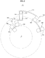
- FIG. 2 is a view illustrating a disposition of link members 210 through 240 in the robot 10.
- FIG. 3 is a view illustrating axes of drive members 250 through 280 being positioned at an identical point in the robot 10.
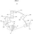
- FIG. 4 is a view illustrating a radiation range of an emitting member 300 of the robot 10.
- FIG. 5 is a view illustrating angle adjustment elements disposed in the robot 10.
- the robot 10 may include a central member 100, and a plurality of robot arms 200 connected to both ends of the central member 100.
- FIG. 1 illustrates two robot arms provided in the robot 10.
- the present invention is not limited thereto. A number of robot arms may vary.
- the plurality of robot arms 200 may be connected to different portions of the central member 100.
- the plurality of robot arms 200 may be disposed at an upper portion and a lower portion of the central member 10 to be spaced from each other.
- a length of the central member 100 may vary depending on a number of robot arms 200.
- the central member 100 may have a longitudinal axis X A .
- the plurality of robot arms 200 may rotate on the longitudinal axis X A of the central member 100.
- the plurality of robot arms 200 may be independently controlled to rotate in different directions or at different velocities.
- the plurality of robot arms 200 may rotate independently and incoherently with respect to each other. Trajectories of rotation of the plurality of robot arms 200 may be present in different areas and thus, the plurality of robot arms 200 may rotate without a mutual collision.
- one robot arm 200 may be disposed at an upper portion of the central member 100, and the other robot arm 200 may be disposed at a lower portion of the central member 100.
- the one robot arm 200 disposed at the upper portion of the central member 100 may include a first link member 210 and a second link member 220.
- the other robot arm 200 disposed at the lower portion of the central member 100 may include a third link member 230 and a fourth link member 240.
- the first link member 210, the second link member 220, the third link member 230, and the fourth link member 240 may be disposed on concentric spheres, and disposed to be spaced from each other radially from a central point O.
- the first link member 210, the second link member 220, the third link member 230, and the fourth link member 240 may be provided in a form of arcs, and have different lengths.
- first link member 210 the form of the first link member 210, the second link member 220, the third link member 230, and the fourth link member 240 is not limited thereto.
- the first link member 210, the second link member 220, the third link member 230, and the fourth link member 240 may be provided in an angular form.
- the first link member 210 and the second link member 220 may be disposed on larger concentric spheres than the third link member 230 and the fourth link member 240.
- the first link member 210 may be disposed on a larger concentric sphere than the second link member 220.
- the third link member 230 may be disposed on a larger concentric sphere than the fourth link member 240.
- first link member 210 and the second link member 220 are disposed on larger concentric spheres than the third link member 230 and located farther away from the central point O, a mutual collision may be prevented although the plurality of link members 210 through 240 simultaneously rotate.
- first link member 210 and the second link member 220 may have greater lengths than the third link member 230 and the fourth link member 240.
- the first link member 210 may have a greater length than the second link member 220.
- the third link member 230 may have a greater length than the fourth link member 240.
- the third link member 230 When the third link member 230 is disposed between the first link member 210 and the second link member 220, the third link member 230 has a shorter length than the first link member 210, and the fourth link member 240 is disposed closer to the central point O than the second link member 220, a mutual collision may be prevented although the plurality of link members 210 through 240 simultaneously rotate.
- the plurality of link members 210 through 240 may be disposed on concentric spheres to be spaced from each other and thus, rotate in different areas, thereby rotating incoherently.
- the plurality of link members 210 through 240 may rotate by means of a drive member.
- a plurality of drive members may be provided.
- the plurality of drive members may include a first drive member 250, a second drive member 260, a third drive member 270, and a fourth drive member 280.
- the first drive member 250 may disposed at one end of the first link member 210 to transmit a torque to the first link member 210.
- the first drive member 250 may be connected to be perpendicular to the one end of the first link member 210.
- the first drive member 250 may be connected to be perpendicular to a tangential direction at the one end of the first link member 210.
- the first drive member 250 may be included in the central member 100.
- the central member 100 may include a space in which the first drive member 250 is to be disposed.
- the first drive member 250 may enable the first link member 210 to rotate on the longitudinal axis X A of the central member 100.
- the first link member 210 may move along a trajectory of rotation on one of the concentric spheres by means of the first drive member 250.
- the second drive member 260 may be disposed between the first link member 210 and the second link member 220 to transmit a torque to the second link member 220.
- the second drive member 220 may rotate on a first axis X 1 extending from the central point O to the second drive member 260.
- the first axis X 1 may be formed to tilt from the longitudinal axis X A of the central member 100.
- the longitudinal axis X A of the central member 100 and the first axis X 1 may extend to be positioned at an identical point, for example, the central point O.
- the second drive member 260 may be connected to be perpendicular to one end of the second link member 220. Since the first link member 210 and the second link member 220 may be disposed on concentric spheres, the second drive member 260 may also be connected to be perpendicular to another end of the first link member 210.
- the second link member 220 may move along a trajectory of rotation on one of the concentric spheres by means of the second drive member 260.
- the trajectory of rotation of the first link member 210 may be greater than the trajectory of rotation of the second link member 220.
- the third drive member 270 may be disposed at one end of the third link member 230 to transmit a torque to the third link member 230.
- the third drive member 270 may be included in the central member 100. Although not illustrated in detail, it is obvious that the central member 100 may include a space in which the third drive member 270 is to be disposed.
- the third drive member 270 may also rotate on the longitudinal axis X A of the central member 100.
- the first drive member 250 and the third drive member 270 may be provided separately or integrally.
- first link member 210 and the third link member 230 may rotate in identical directions or at identical velocities.
- first link member 210 and the third link member 230 may rotate independently.
- the third drive member 270 may be connected to be perpendicular to an end portion of the first link member 210 and an end portion of the third link member 230.
- the third link member 230 may move along a trajectory of rotation on one of the concentric spheres by means of the third drive member 270 disposed as described above.
- the trajectory of rotation of the third link member 230 may be smaller than the trajectories of rotation of the first link member 210 and the second link member 220.
- the trajectory of rotation of the third link member 230 may be closer to the central point O than the trajectories of rotation of the first link member 210 and the second link member 220.
- the fourth drive member 280 may be disposed between the third link member 230 and the fourth link member 240 to transmit a torque to the fourth link member 240.
- the fourth link member 240 may rotate on a second axis X 2 extending from the central point O to the fourth drive member 280.
- the second axis X 2 may be formed to tilt from the longitudinal axis X A of the central member 100.
- the longitudinal axis X A of the central member 100 and the second axis X 2 may be positioned at an identical point, for example, the central point O.
- the fourth drive member 280 may be connected to be perpendicular to one end of the fourth link member 240. Since the third link member 230 and the fourth link member 240 may be disposed on concentric spheres, the fourth drive member 280 may be connected to be perpendicular to another end of the third link member 230.
- the fourth link member 240 may move along a trajectory of rotation on one of the concentric spheres by means of the fourth drive member 280.
- the trajectory of rotation of the fourth link member 240 may be smaller than the trajectory of rotation of the third link member 230.
- the robot arms 200 may further include a fifth link member, a sixth link member, a fifth drive member, and a sixth drive member.
- the fifth link member may be connected to a portion of the central member 100 to rotate on the longitudinal axis X A of the central member 100.
- the portion of the central member 100 to which the fifth link member is connected may differ from the portions to which the first link member 210 and the third link member 230 are connected.
- the fifth link member may be disposed at an upper portion or a lower portion than the first link member 210 and the third link member 230.
- the sixth link member may be disposed at another end of the fifth link member to rotate on a third axis.
- the third axis may be formed to tilt with respect to the longitudinal axis X A of the central member 100.
- the fifth drive member may be disposed at one end of the fifth link member to transmit a torque to the fifth link member.
- the fifth drive member may be included in the central member 100.
- the sixth drive member may be disposed between the fifth link member and the sixth link member to transmit a torque to the sixth link member.
- the longitudinal axis X A of the central member 100 and the third axis may be positioned at the central point O or an identical location of a target.
- a number of the drive members may be fewer than or equal to a number of the link members.
- a single drive member may be disposed at a single link member and thus, each link member may operate independently.
- a plurality of link members may be disposed at a single drive member and thus, the plurality of link members may operate simultaneously.
- the robot 10 may aim at a target or an affected area more accurately, and access to an area difficult to reach with a high degree of freedom.
- the robot 10 may save a space occupied by the link members 210 through 240 and the drive members 250 through 280, and reduce an operation time through easy control over the link members 210 through 240 and the drive members 250 through 280.
- the emitting member 300 may be disposed at another end of a robot arm 200.
- the emitting member 300 will be described based on a linear accelerator that emits radiation for radiation therapy.
- the emitting member 300 is not limited thereto.
- the emitting member 300 may emit another material including a liquid or gas.
- the emitting member 300 may include a first emitting member 310 disposed at an end portion of the second link member 220, and a second emitting member 320 disposed at an end portion of the fourth link member 240.
- the first emitting member 310 and the second emitting member 320 may be connected to be perpendicular to the end portion of the second link member 220 and the end portion of the fourth link member 240, respectively.
- the first emitting member 310 and the second emitting member 320 may be provided to face the central point O, that is, the identical point at which the first axis X 1 of the second drive member 260 and the second axis X 2 of the fourth drive member 280 are positioned.
- first axis X 1 of the second drive member 260 and the second axis X 2 of the fourth drive member 280 may be positioned at the identical point, for example, the central point O, along with the longitudinal axis X A of the central member 100.
- the longitudinal axis X A of the central member 100, the first axis X 1 , and the second axis X 2 may be positioned at the central point O, and the first emitting member 310 and the second emitting member 320 may also face the central point O.
- the radiation When radiation is emitted from the emitting member 300 for treatment or surgery on a patient, the radiation may be emitted toward the central point O.
- the first emitting member 310 and the second emitting member 320 may be continuously aimed at the central point O while the link members 210 through 240 are rotating, due to a structural disposition of the link members 210 through 240 and the drive members 250 through 280.
- Radiation may be emitted in a state in which a robot arm 200 is stationary. Thus, radiation may not be emitted while the robot arm 200 is moving to a subsequent emission point.
- a radiation area of the emitting member 300 is illustrated.
- the first emitting member 310 may emit radiation within an area A through rotation of the first link member 210 and the second link member 220.
- the second emitting member 320 may emit radiation within an area B through rotation of the third link member 230 and the fourth link member 240.
- the area A may be larger than the area B.
- the area A may represent a greater sphere than the area B.
- the first emitting member 310 and the second emitting member 320 may emit radiation toward a target T within the area A and the area B at all times.
- the link members 210 through 240 may move spherically along trajectories of rotation
- the first emitting member 310 disposed at the second link member 220 and the second emitting member 320 disposed at the fourth link member 240 may move spherically along the trajectories of rotation.
- the first emitting member 310 and the second emitting member 320 may be easily aimed at the target T.
- the angle adjustment elements may be additionally provided at end potions of the second link member 220 and the fourth link member 240 or the emitting member 300.
- the angle adjustment elements may include a first angle adjustment element 312 disposed at a point at which the first emitting member 310 and the second link member 220 meet, and a second angle adjustment element 322 disposed at a point at which the second emitting member 320 and the fourth link member 240 meet.
- the first emitting member 310 and the second emitting member 320 may oscillate while moving in directions of arrows on axes extending from the emitting member 300 toward the central point O.
- the first emitting member 310 including the first angle adjustment element 312 and the second emitting member 320 including the second angle adjustment element 322 may perform small-angle movements.
- the first angle adjustment element 312 and the second angle adjustment element 322 may be useful when a minute angle adjustment is required after the first emitting member 310 and the second emitting member 320 aims at a target by means of the drive members 250 through 280.
- a robot may reduce a treatment or surgery time by aiming at a target more rapidly and accurately using a plurality of robot arms, increase a directivity with respect to the target through easy control, and reduce an overall weight through a compact design.
- the robot may prevent a mutual collision between a plurality of link members by rotating the link members independently and incoherently, and efficiently adjust an angle at which an emitting member faces the target through an additional angle adjustment element disposed at the emitting member.
- Equation 1 ⁇ denotes a joint angle, and x denotes a location and direction of an end-effector.
- Coordinates of an emitting member may be estimated based on an angle at which link members are connected to each other.
- the kinematics of the robot may include four parameters, for example, a link length a of a line member, a link offset d, a link distortion ⁇ , and a joint angle ⁇ .
- D-H Denavit-Hartenberg
- transformation matrices may be expressed as follows.
- the above transformation matrix may represent a case in which two link members are provided.
- a point to which relocation is to be performed by a translation, an offset, a scale, or a rotation on a three-dimensional (3D) coordinate system may be estimated using the transformation matrix.
- the location of the emitting member or the end-effector may be constantly uniform.
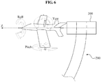
- FIG. 6 illustrates a direction of an emitting member in a robot according to an embodiment of the present invention.
- the emitting member may face a z axis, and have a roll movement of rotating on the z axis, a yaw movement of oscillating up and down based on the z axis, and a pitch movement of rotating up and down based on the z axis.
- a roll direction may be insignificant in the emitting member.
- Only a z-vector may be considered for a direction of the emitting member.
- Transformation Matrix 2 may be arranged as follows.
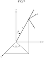
- a desired direction of the emitting member may be designated as spherical coordinates ⁇ and ⁇ of FIG. 7 .
- rotation matrices corresponding to the direction may be expressed as follows.
- R spherical x 1 y 1 z 1 x 2 y 2 z 2 x 3 y 3 z 3
- 0 x 2 [x 1 , x 2 , x 3 ] T
- 0 y 2 [y 1 , y 2 , y 3 ] T
- 0 z 2 [z 1 , z 2 , z 3] T
- Equation 2 may be an inverse function of Equation 1.
- the joints angles ⁇ 1 and ⁇ 2 may be calculated based on orthonormal vectors 0 x 2 , 0 y 2 , and 0 z 2 .
- An intuitive method of calculating such vectors may be performed using spherical coordinates.
- a rotation matrix corresponding to the direction may be expressed as follows.
- ⁇ 2 may be induced as follows.
- a function arctan2 an arctangent function including two input variables, may be used due to a stability of being close to zero input values and a characteristic of a final angle returning to an appropriate quadrant.
- ⁇ 1 may be calculated as follows.
- Equations 5 through 7 may be obtained from Transformation Matrix 4.
- Equations 7 and 8 the following may be calculated.
- a ( z 1 as ⁇ 1 + bc ⁇ 1 )
- b ( z 2 ⁇ ac ⁇ 1 + bs ⁇ 1 )
- az 1 a 2 s ⁇ 1 + abc ⁇ 1
- Equations 4 and 10 the two joint angles ⁇ 1 and ⁇ 2 may be determined.
- a Jacobian matrix will be described hereinafter.
- the Jacobian matrix may be expressed as follows.
- a relationship between a movement of a link member and a movement of an emitting member may be expressed through a Jacobian matrix.
- the movement of the emitting member may be estimated based on the movement of the link member.
- a location of the emitting member may be estimated based on a current location of a link member.
- an operation of a link member may be controlled based on a current location of the emitting member.
- the plurality of robot arms may be controlled to operate collaboratively through a Jacobian matrix.
Landscapes
- Engineering & Computer Science (AREA)
- Health & Medical Sciences (AREA)
- Life Sciences & Earth Sciences (AREA)
- Biomedical Technology (AREA)
- Medical Informatics (AREA)
- Pathology (AREA)
- Animal Behavior & Ethology (AREA)
- Veterinary Medicine (AREA)
- Public Health (AREA)
- General Health & Medical Sciences (AREA)
- Nuclear Medicine, Radiotherapy & Molecular Imaging (AREA)
- Radiology & Medical Imaging (AREA)
- Robotics (AREA)
- Physics & Mathematics (AREA)
- Optics & Photonics (AREA)
- Heart & Thoracic Surgery (AREA)
- Molecular Biology (AREA)
- Surgery (AREA)
- Mechanical Engineering (AREA)
- High Energy & Nuclear Physics (AREA)
- Biophysics (AREA)
- Automation & Control Theory (AREA)
- Manipulator (AREA)
- Radiation-Therapy Devices (AREA)
- Apparatus For Radiation Diagnosis (AREA)
Claims (16)
- Roboter (10), umfassend:ein zentrales Glied (100); undeine Vielzahl von Roboterarmen, wobei jeder Roboterarm ein Ende aufweist, das mit dem zentralen Glied (100) verbunden ist, um sich um eine Längsachse (XA) des zentralen Glieds (100) zu drehen,wobei jeder Roboterarm mit verschiedenen Abschnitten des zentralen Glieds(100) verbunden ist, um sich unabhängig voneinander zu drehen,wobei jeder Roboterarm Folgendes umfasst:eine Vielzahl von Verbindungsgliedern; undeine Vielzahl von Antriebsgliedern zum Drehen der Vielzahl von Verbindungsgliedern, dadurch gekennzeichnet, dass jedes Verbindungsglied in einer Bogenform vorgesehen ist und auf einer jeweiligen konzentrischen Kugel mit einem identischen Mittelpunkt (O) angeordnet istjedes Verbindungsgliedangeordnet ist, um von dem identischen Mittelpunkt (O) radial beabstandet zu sein, unddie Vielzahl von Verbindungsgliedern so angeordnet ist, dass die Verbindungsglieder radial voneinander beabstandet sind, um sich inkohärent in Bezug zueinander zu drehen.
- Roboter nach Anspruch 1, wobei sich die Drehachsen der Antriebsglieder an dem identischen Mittelpunkt (O) überschneiden.
- Roboter nach Anspruch 2, wobei jedes Antriebsglied an einem Endabschnitt jedes Verbindungsgliedes angeordnet ist.
- Roboter nach Anspruch 3, wobei die Achsen der Antriebsglieder so ausgebildet sind, dass sie senkrecht zu der tangentialen Richtung der Endabschnitte der Verbindungsglieder sind.
- Roboter nach Anspruch 4, wobei die Längen der Verbindungsglieder basierend auf Winkeln zwischen den Drehachsen der Antriebsglieder bestimmt werden.
- Roboter nach Anspruch 1, wobei am anderen Ende jedes Roboterarms emittierende Glieder (310, 320) vorgesehen sind, die entlang einer Rotationsbahn jedes Roboterarms sphärisch bewegt werden.
- Roboter nach Anspruch 6, wobei die emittierenden Glieder senkrecht zu tangentialen Richtungen des Endabschnitts jedes Roboterarms angeordnet sind.
- Roboter nach Anspruch 6, wobei Winkeleinstellglieder (312, 322) am Endabschnitt jedes Roboterarms oder an jedem emittierenden Glied (310, 320) angeordnet sind, um Winkel einzustellen, unter dem jedes emittierende Glied einem Punkt gegenüberliegt, der zu einem Ziel (T) gehört.
- Roboter nach Anspruch 1, wobei ein Roboterarm Folgendes umfasst:ein erstes Verbindungsglied (210), das sich um eine Längsachse (XA) des zentralen Glieds dreht;ein erstes Antriebsglied (250), das an einem Ende des ersten Verbindungsglieds (210) angeordnet ist, um ein Drehmoment auf das erste Verbindungsglied (210) zu übertragen;ein zweites Verbindungsglied (220), das mit einem anderen Ende des ersten Verbindungsgliedes (210) verbunden ist, um sich um eine erste Achse (X1) zu drehen; undein zweites Antriebsglied (260), das zwischen dem ersten Verbindungsglied (210) und dem zweiten Verbindungsglied (220) angeordnet ist, um ein Drehmoment auf das zweite Verbindungsglied (220) zu übertragen.
- Roboter nach Anspruch 9, wobei ein anderer Roboterarm Folgendes umfasst:ein drittes Verbindungsglied (230), das mit einem Abschnitt des zentralen Glieds (100) verbunden ist, wobei sich der Abschnitt von einem Abschnitt unterscheidet, mit dem das erste Verbindungsglied (210) verbunden ist, um sich auf der Längsachse (XA) des Zentralgliedes (100) drehen;ein drittes Antriebsglied (270), das an einem Ende des dritten Verbindungsglieds (230) angeordnet ist, um ein Drehmoment auf das dritte Verbindungsglied (230) zu übertragen;ein viertes Verbindungsglied (240), das mit einem anderen Ende des dritten Verbindungsglieds (230) verbunden ist, um sich auf einer zweiten Achse (X2) zu drehen; undein viertes Antriebsglied (280), das zwischen dem dritten Verbindungsglied (230) und dem vierten Verbindungsglied (240) angeordnet ist, um ein Drehmoment auf das vierte Verbindungsglied (240) zu übertragen.
- Roboter nach Anspruch 10, wobei die Längsachse (XA) des zentralen Glieds (100), die erste Achse (X1) und die zweite Achse (X2) sich an einem Punkt überschneiden, der zu einem Ziel (T) gehört.
- Roboter nach Anspruch 11, weiter Folgendes umfassend:
emittierende Glieder (310, 320), die an Endabschnitten des zweiten Verbindungsgliedes (220) und des vierten Verbindungsgliedes (240) so angeordnet sind, dass sie dem Punkt gegenüberliegen, der zu dem Ziel (T) gehört. - Roboter nach Anspruch 11
wobei das erste Verbindungsglied (210) und das zweite Verbindungsglied (220) weiter von dem Punkt entfernt sind, der zu dem Ziel (T) gehört, als das dritte Verbindungsglied (230) und das vierte Verbindungsglied (240). - Roboter nach Anspruch 13, wobei das vierte Verbindungsglied (240) näher an dem zu dem Ziel (T) gehörenden Punkt angeordnet ist als das dritte Verbindungsglied (230).
- Roboter nach Anspruch 11
wobei eine Länge des dritten Verbindungsgliedes (230) kürzer als eine Länge des ersten Verbindungsgliedes (210) ist und das vierte Verbindungsglied (240) näher zu dem Punkt ist, der zu dem Ziel (T) gehört, als das zweite Verbindungsglied (220). - Roboter nach Anspruch 14, der andere Roboterarm umfasst:ein fünftes Verbindungsglied, das mit einem Abschnitt des zentralen Glieds (100) verbunden ist, wobei sich der Abschnitt von Abschnitten unterscheidet, mit denen das erste Verbindungsglied (210) und das dritte Verbindungsglied (230) verbunden sind, um sich auf der Längsachse (XA) des Zentralgliedes (100) zu drehen;ein fünftes Antriebsglied, das an einem Ende des fünften Verbindungsgliedes angeordnet ist, um ein Drehmoment auf das fünfte Verbindungsglied zu übertragen;ein sechstes Verbindungsglied, das mit einem anderen Ende des fünften Verbindungsglieder verbunden ist, um sich um eine dritte Achse zu drehen;ein sechstes Antriebsglied, das zwischen dem fünften Verbindungsglied und dem sechsten Verbindungsglied angeordnet ist, um ein Drehmoment auf das sechste Verbindungsglied zu übertragen; undein emittierenden Glied, das an einem Endabschnitt des sechsten Verbindungsgliedes so angeordnet ist, dass es dem Punkt zugewandt ist, der zu dem Ziel (T) gehört,wobei die Längsachse (XA) des zentralen Glieds (100) und die dritte Achse sich an einem Punkt überschneiden, der zu dem Ziel (T) gehört.
Applications Claiming Priority (2)
| Application Number | Priority Date | Filing Date | Title |
|---|---|---|---|
| KR1020140041388A KR101485292B1 (ko) | 2014-04-07 | 2014-04-07 | 로봇 |
| PCT/KR2014/010946 WO2015156471A1 (en) | 2014-04-07 | 2014-11-14 | Robot |
Publications (3)
| Publication Number | Publication Date |
|---|---|
| EP2999573A1 EP2999573A1 (de) | 2016-03-30 |
| EP2999573A4 EP2999573A4 (de) | 2018-04-11 |
| EP2999573B1 true EP2999573B1 (de) | 2019-06-12 |
Family
ID=52592294
Family Applications (1)
| Application Number | Title | Priority Date | Filing Date |
|---|---|---|---|
| EP14866813.0A Active EP2999573B1 (de) | 2014-04-07 | 2014-11-14 | Roboter |
Country Status (6)
| Country | Link |
|---|---|
| US (1) | US9855446B2 (de) |
| EP (1) | EP2999573B1 (de) |
| JP (1) | JP6059401B2 (de) |
| KR (1) | KR101485292B1 (de) |
| CN (1) | CN105324220B (de) |
| WO (1) | WO2015156471A1 (de) |
Families Citing this family (7)
| Publication number | Priority date | Publication date | Assignee | Title |
|---|---|---|---|---|
| KR101403787B1 (ko) * | 2014-04-07 | 2014-06-03 | 재단법인대구경북과학기술원 | 의료용 로봇 |
| US10151710B2 (en) * | 2014-07-18 | 2018-12-11 | Peltec Services, Inc. | Portable industrial radiography apparatus |
| CN206228357U (zh) * | 2016-06-03 | 2017-06-09 | 北京东软医疗设备有限公司 | 一种悬吊机架 |
| GB2552019B (en) | 2016-07-08 | 2020-01-08 | Rolls Royce Plc | Methods and apparatus for controlling at least one of a first robot and a second robot to collaborate within a system |
| EP3534795B1 (de) * | 2016-11-04 | 2021-01-13 | Hologic, Inc. | Medizinische bildgebungsvorrichtung |
| GB2575635A (en) * | 2018-07-16 | 2020-01-22 | Vaakalintu Oy | Unpredictably responsive training device |
| WO2022240894A1 (en) * | 2021-05-11 | 2022-11-17 | Celestial Oncology Inc. | Coupled robotic radiation therapy system |
Family Cites Families (81)
| Publication number | Priority date | Publication date | Assignee | Title |
|---|---|---|---|---|
| EP0220501B1 (de) * | 1985-10-09 | 1989-05-31 | Siemens Aktiengesellschaft | Röntgendiagnostikanlage mit durch eine Steuervorrichtung verstellbaren Anlagenkomponenten |
| US5078140A (en) * | 1986-05-08 | 1992-01-07 | Kwoh Yik S | Imaging device - aided robotic stereotaxis system |
| NL9200286A (nl) * | 1992-02-17 | 1993-09-16 | Sven Ploem | Botsvrij besturingssysteem voor een meerassig bestuurbare manipulator. |
| IT1281184B1 (it) * | 1994-09-19 | 1998-02-17 | Giorgio Trozzi Amministratore | Apparecchiatura per la radioterapia intraoperatoria mediante acceleratori lineari utilizzabili direttamente in sala operatoria |
| JPH1110564A (ja) * | 1997-06-23 | 1999-01-19 | Olympus Optical Co Ltd | 微細組立て装置 |
| FI103761B1 (fi) * | 1997-12-12 | 1999-09-30 | Planmeca Oy | Lääketieteellinen kuvantamislaite |
| DE19827022C2 (de) * | 1998-06-17 | 2002-01-03 | Siemens Ag | Medizinisches Gerät |
| US6200024B1 (en) * | 1998-11-27 | 2001-03-13 | Picker International, Inc. | Virtual C-arm robotic positioning system for use in radiographic imaging equipment |
| DE19855213C2 (de) * | 1998-11-30 | 2001-03-15 | Siemens Ag | Röntgenaufnahmeeinrichtung |
| DE19917089C1 (de) * | 1999-04-15 | 2000-08-24 | Siemens Ag | Medizinisches Behandlungs- und Versorgungszentrum |
| DE19958864A1 (de) * | 1999-12-07 | 2001-06-13 | Philips Corp Intellectual Pty | Röntgeneinrichtung |
| JP2002253687A (ja) | 2001-03-02 | 2002-09-10 | Mitsubishi Heavy Ind Ltd | 放射線医療装置 |
| EP2145650A1 (de) * | 2001-08-24 | 2010-01-20 | Mitsubishi Heavy Industries, Ltd. | Strahlenbehandlungsvorrichtung |
| WO2003018133A1 (en) * | 2001-08-24 | 2003-03-06 | Mitsubishi Heavy Industries, Ltd. | Radiotherapy device |
| US6590958B2 (en) * | 2001-11-15 | 2003-07-08 | Ge Medical Systems Global Technology | X-ray positioner having integrated display |
| US6644852B2 (en) * | 2001-11-15 | 2003-11-11 | Ge Medical Systems Global Technology | Automatically reconfigurable x-ray positioner |
| US6592259B2 (en) * | 2001-11-15 | 2003-07-15 | Ge Medical Systems Global Technology | Scaleable x-ray positioner |
| US6582121B2 (en) * | 2001-11-15 | 2003-06-24 | Ge Medical Systems Global Technology | X-ray positioner with side-mounted, independently articulated arms |
| US6637936B2 (en) * | 2001-11-15 | 2003-10-28 | Ge Medical Systems Global Technology | Bolus tracking x-ray positioner |
| US7891935B2 (en) * | 2002-05-09 | 2011-02-22 | Brooks Automation, Inc. | Dual arm robot |
| KR100467327B1 (ko) | 2002-12-11 | 2005-01-24 | 한국전자통신연구원 | 경로 설정 메시지를 이용한 네트워크 경로 정보 전달 방법 |
| US7945021B2 (en) * | 2002-12-18 | 2011-05-17 | Varian Medical Systems, Inc. | Multi-mode cone beam CT radiotherapy simulator and treatment machine with a flat panel imager |
| JP4086690B2 (ja) * | 2003-03-19 | 2008-05-14 | キヤノン株式会社 | マニピュレータ |
| WO2006042211A2 (en) * | 2004-10-07 | 2006-04-20 | University Of Florida Research Foundation, Inc. | Radiographic medical imaging system using robot mounted source and sensor for dynamic image capture and tomography |
| JP4974118B2 (ja) | 2005-02-12 | 2012-07-11 | アプライド マテリアルズ インコーポレイテッド | 多軸真空モータアセンブリ |
| US7239684B2 (en) * | 2005-02-28 | 2007-07-03 | Mitsubishi Heavy Industries, Ltd. | Radiotherapy apparatus monitoring therapeutic field in real-time during treatment |
| DE102005012700B4 (de) * | 2005-03-18 | 2012-08-23 | Siemens Ag | Röntgenvorrichtung |
| DE102005030609A1 (de) * | 2005-06-30 | 2007-01-04 | Siemens Ag | Verfahren bzw. Röntgeneinrichtung zum Erstellen einer Serienaufnahme von medizinischen Röntgenbildern eines sich während der Serienaufnahme ggf. bewegenden Patienten |
| DE102005032288B4 (de) * | 2005-07-11 | 2008-10-16 | Siemens Ag | Röntgenaufnahmeeinrichtung |
| US7266176B2 (en) * | 2005-09-28 | 2007-09-04 | Accuray Incorporated | Workspace optimization for radiation treatment delivery system |
| GB0521281D0 (en) * | 2005-10-19 | 2005-11-30 | Acrobat Company The Ltd | hybrid constrant mechanism |
| US8469945B2 (en) * | 2006-01-25 | 2013-06-25 | Intuitive Surgical Operations, Inc. | Center robotic arm with five-bar spherical linkage for endoscopic camera |
| US20070189455A1 (en) * | 2006-02-14 | 2007-08-16 | Accuray Incorporated | Adaptive x-ray control |
| US7590219B2 (en) * | 2006-04-07 | 2009-09-15 | Accuray Incorporated | Automatically determining a beam parameter for radiation treatment planning |
| DE102006028327B3 (de) * | 2006-06-20 | 2008-01-31 | Siemens Ag | Robotergesteuerte Aufzeichnungsvorrichtung, insbesondere für die Aufzeichnung von Röntgenbilddaten, sowie zugehöriges Verfahren |
| US7620144B2 (en) * | 2006-06-28 | 2009-11-17 | Accuray Incorporated | Parallel stereovision geometry in image-guided radiosurgery |
| US7693257B2 (en) * | 2006-06-29 | 2010-04-06 | Accuray Incorporated | Treatment delivery optimization |
| US7505559B2 (en) * | 2006-08-25 | 2009-03-17 | Accuray Incorporated | Determining a target-to-surface distance and using it for real time absorbed dose calculation and compensation |
| US7894649B2 (en) * | 2006-11-02 | 2011-02-22 | Accuray Incorporated | Target tracking using direct target registration |
| US8262554B2 (en) * | 2007-03-30 | 2012-09-11 | Accuray Incorporated | Apparatus and method for determining an optimized path traversal for radiation treatment delivery system |
| DE102007023847B4 (de) * | 2007-05-23 | 2011-12-08 | Siemens Ag | Schultergelenk |
| DE102007023848B4 (de) * | 2007-05-23 | 2012-08-02 | Siemens Ag | Schultergelenk |
| US7623623B2 (en) * | 2007-06-29 | 2009-11-24 | Accuray Incorporated | Non-collocated imaging and treatment in image-guided radiation treatment systems |
| DE102007033716B4 (de) * | 2007-07-19 | 2012-03-01 | Siemens Ag | Röntgenbiplananlage |
| US8606348B2 (en) * | 2007-07-20 | 2013-12-10 | Siemens Aktiengesellschaft | System and method for performing at least one of a vertebroplasty procedure, a kyphoplasty procedure, an electroencephalography (EEG) procedure and intraoperative electromyography (EMG) procedure using a robot-controlled imaging system |
| KR100945536B1 (ko) | 2007-10-15 | 2010-03-09 | 지씨티 세미컨덕터 인코포레이티드 | 무선 통신 기술들의 공존을 지원하는 방법 |
| DE102007058990B4 (de) * | 2007-12-07 | 2012-05-24 | Siemens Ag | Medizinische Untersuchungseinrichtung, insbesondere Röntgeneinrichtung |
| DE102008003088B4 (de) * | 2008-01-03 | 2013-05-16 | Siemens Aktiengesellschaft | Röntgeneinrichtung umfassend einen C-Bogen, an dem eine Strahlungsquelle nebst Wärmepumpe angeordnet ist |
| US7720196B2 (en) * | 2008-01-07 | 2010-05-18 | Accuray Incorporated | Target tracking using surface scanner and four-dimensional diagnostic imaging data |
| DE102008003815B4 (de) * | 2008-01-10 | 2014-07-31 | Siemens Aktiengesellschaft | Röntgeneinrichtung umfassend einen vorzugsweise an einem Roboterarm um eine Drehachse drehbar gelagerten C-Bogen |
| DE102008003816B4 (de) * | 2008-01-10 | 2013-08-01 | Siemens Aktiengesellschaft | Röntgeneinrichtung umfassend einen vorzugsweise an einem Roboterarm drehgelagerten C-Bogen |
| US8295435B2 (en) * | 2008-01-16 | 2012-10-23 | Accuray Incorporated | Cardiac target tracking |
| DE102008016414B4 (de) * | 2008-03-31 | 2018-01-04 | Kuka Roboter Gmbh | Röntgenvorrichtung und medizinischer Arbeitsplatz |
| DE102008019128A1 (de) * | 2008-04-16 | 2009-10-29 | Siemens Aktiengesellschaft | Vorrichtung zur Durchführung einer Bestrahlung und Verfahren zur Überwachung einer solchen |
| US7724870B2 (en) * | 2008-05-30 | 2010-05-25 | Siemens Medical Solutions Usa, Inc. | Digital tomosynthesis in robotic stereotactic radiosurgery |
| DE102008032294A1 (de) * | 2008-07-09 | 2010-01-14 | Siemens Aktiengesellschaft | Röntgeneinrichtung |
| EP2334233A4 (de) * | 2008-09-12 | 2013-02-27 | Accuray Inc | Steuerung einer röntgenbildgebung auf basis von zielbewegungen |
| US8126114B2 (en) * | 2008-09-12 | 2012-02-28 | Accuray Incorporated | Seven or more degrees of freedom robotic manipulator having at least one redundant joint |
| US8180020B2 (en) * | 2008-10-23 | 2012-05-15 | Accuray Incorporated | Sequential optimizations for treatment planning |
| KR20100119106A (ko) | 2009-04-30 | 2010-11-09 | 주식회사 서울씨앤제이 | 방사선 치료계획정보 통합조회시스템 |
| US7934869B2 (en) * | 2009-06-30 | 2011-05-03 | Mitsubishi Electric Research Labs, Inc. | Positioning an object based on aligned images of the object |
| DE102009049075B4 (de) * | 2009-10-12 | 2021-09-30 | Siemens Healthcare Gmbh | Röntgensystem, Verfahren und digital lesbares Medium zum Generieren einer Abtastbahn |
| DE102010008240B4 (de) * | 2010-02-17 | 2015-10-15 | Siemens Aktiengesellschaft | Verfahren zum Betrieb eines mehrachsigen, vorzugsweise sechsachsigen, Roboters |
| KR200451737Y1 (ko) * | 2010-04-13 | 2011-01-10 | (주)미래컴퍼니 | 수술용 로봇 암의 링크구조 |
| DE102010019990B4 (de) * | 2010-05-10 | 2016-04-07 | Siemens Aktiengesellschaft | Biplan-Röntgenaufnahmesystem |
| DE102010020603A1 (de) * | 2010-05-14 | 2011-11-17 | Siemens Aktiengesellschaft | Bildaufnahmevorrichtung, umfassend eine ringförmige Gantry |
| US8559596B2 (en) * | 2010-06-08 | 2013-10-15 | Accuray Incorporated | Target Tracking for image-guided radiation treatment |
| DE102010038800B4 (de) * | 2010-08-02 | 2024-03-07 | Kuka Deutschland Gmbh | Medizinischer Arbeitsplatz |
| WO2012019162A1 (en) * | 2010-08-06 | 2012-02-09 | Accuray, Inc. | Systems and methods for real-time tumor tracking during radiation treatment using ultrasound imaging |
| US8989846B2 (en) * | 2010-08-08 | 2015-03-24 | Accuray Incorporated | Radiation treatment delivery system with outwardly movable radiation treatment head extending from ring gantry |
| US8315356B2 (en) * | 2010-09-17 | 2012-11-20 | Accuray Incorporated | Image alignment |
| US8824630B2 (en) * | 2010-10-29 | 2014-09-02 | Accuray Incorporated | Method and apparatus for treating a target's partial motion range |
| US8849633B2 (en) * | 2010-10-29 | 2014-09-30 | Accuray Incorporated | Method and apparatus for selecting a tracking method to use in image guided treatment |
| CN102743186B (zh) * | 2011-04-20 | 2014-04-09 | 上海西门子医疗器械有限公司 | 一种可折叠式压迫器及x光机 |
| JP5834473B2 (ja) * | 2011-04-28 | 2015-12-24 | セイコーエプソン株式会社 | ロボット |
| DE102011082075B4 (de) * | 2011-09-02 | 2014-06-26 | Siemens Aktiengesellschaft | Röntgeneinrichtung mit an Tragearmen gehalterter Aufnahmeanordnung |
| US9202733B2 (en) * | 2011-11-07 | 2015-12-01 | Persimmon Technologies Corporation | Robot system with independent arms |
| JP5338000B1 (ja) * | 2012-06-15 | 2013-11-06 | 株式会社アキュセラ | リアルタイム3次元放射線治療装置 |
| WO2014144090A2 (en) * | 2013-03-15 | 2014-09-18 | Leek Paul H | Optionally transportable machine for use in intraoperative electron radiation therapy |
| CN103143124B (zh) * | 2013-04-06 | 2016-05-11 | 吴大可 | 机器人无创放射治疗系统 |
| KR101526115B1 (ko) * | 2014-04-07 | 2015-06-04 | 재단법인대구경북과학기술원 | 3차원 조사 장치 |
-
2014
- 2014-04-07 KR KR1020140041388A patent/KR101485292B1/ko not_active Expired - Fee Related
- 2014-11-13 US US14/541,077 patent/US9855446B2/en active Active
- 2014-11-14 WO PCT/KR2014/010946 patent/WO2015156471A1/en not_active Ceased
- 2014-11-14 EP EP14866813.0A patent/EP2999573B1/de active Active
- 2014-11-14 JP JP2016512861A patent/JP6059401B2/ja active Active
- 2014-11-14 CN CN201480024010.7A patent/CN105324220B/zh active Active
Non-Patent Citations (1)
| Title |
|---|
| None * |
Also Published As
| Publication number | Publication date |
|---|---|
| US9855446B2 (en) | 2018-01-02 |
| JP6059401B2 (ja) | 2017-01-11 |
| US20150283697A1 (en) | 2015-10-08 |
| EP2999573A4 (de) | 2018-04-11 |
| CN105324220B (zh) | 2017-09-12 |
| JP2016519000A (ja) | 2016-06-30 |
| EP2999573A1 (de) | 2016-03-30 |
| KR101485292B1 (ko) | 2015-01-28 |
| WO2015156471A1 (en) | 2015-10-15 |
| CN105324220A (zh) | 2016-02-10 |
Similar Documents
| Publication | Publication Date | Title |
|---|---|---|
| EP3007770B1 (de) | Medizinischer roboter | |
| US9895559B2 (en) | Robot | |
| US9855446B2 (en) | Robot | |
| Kurup | CyberKnife: A new paradigm in radiotherapy | |
| EP2951525B1 (de) | Dreidimensionale 3d-emittierende vorrichtung | |
| Fallahi et al. | Sliding-based switching control for image-guided needle steering in soft tissue | |
| Bernardes et al. | 3D robust online motion planning for steerable needles in dynamic workspaces using duty-cycled rotation | |
| JP6058377B2 (ja) | 粒子線治療装置 | |
| EP3509698B1 (de) | Strahlentherapiesystem zur verhinderung der bestrahlung von gesundem gewebe | |
| US8488741B2 (en) | Adequate clearance for gantry trajectory | |
| US10632326B2 (en) | System and method for radiation treatment optimized for non-coplanar delivery | |
| Gherman et al. | Kinematic analysis of two innovative medical instruments for the robotic assisted treatment of non-resectable liver tumors | |
| US11058895B2 (en) | Collimator and medical robot including the same | |
| Chung et al. | Feasibility study of robotics-based patient immobilization device for real-time motion compensation | |
| Bodduluri et al. | X‐ray guided robotic radiosurgery for solid tumors | |
| Sadeghian et al. | Robotic needle positioning based on ct-scan images: Constrained admittance realization | |
| ZarroukT et al. | Vision-based magnetic platform for actuator positioning and wireless control of microrobots | |
| Buzurovic et al. | Robotic systems for radiation therapy | |
| Abbes et al. | Robotic Manipulator for Positioning a Magnetic Actuator Dedicated to Drug Delivery in the Cochlea |
Legal Events
| Date | Code | Title | Description |
|---|---|---|---|
| PUAI | Public reference made under article 153(3) epc to a published international application that has entered the european phase |
Free format text: ORIGINAL CODE: 0009012 |
|
| 17P | Request for examination filed |
Effective date: 20150611 |
|
| AK | Designated contracting states |
Kind code of ref document: A1 Designated state(s): AL AT BE BG CH CY CZ DE DK EE ES FI FR GB GR HR HU IE IS IT LI LT LU LV MC MK MT NL NO PL PT RO RS SE SI SK SM TR |
|
| AX | Request for extension of the european patent |
Extension state: BA ME |
|
| DAX | Request for extension of the european patent (deleted) | ||
| A4 | Supplementary search report drawn up and despatched |
Effective date: 20180308 |
|
| RIC1 | Information provided on ipc code assigned before grant |
Ipc: B25J 9/00 20060101ALI20180303BHEP Ipc: B25J 9/02 20060101AFI20180303BHEP Ipc: B25J 18/00 20060101ALI20180303BHEP Ipc: B25J 9/06 20060101ALI20180303BHEP Ipc: A61N 5/01 20060101ALI20180303BHEP Ipc: A61N 5/10 20060101ALI20180303BHEP |
|
| RIC1 | Information provided on ipc code assigned before grant |
Ipc: B25J 9/02 20060101AFI20181126BHEP Ipc: B25J 9/06 20060101ALI20181126BHEP Ipc: A61N 5/10 20060101ALI20181126BHEP Ipc: A61N 5/01 20060101ALI20181126BHEP Ipc: A61B 6/00 20060101ALI20181126BHEP Ipc: B25J 9/00 20060101ALI20181126BHEP Ipc: B25J 18/00 20060101ALI20181126BHEP |
|
| GRAP | Despatch of communication of intention to grant a patent |
Free format text: ORIGINAL CODE: EPIDOSNIGR1 |
|
| STAA | Information on the status of an ep patent application or granted ep patent |
Free format text: STATUS: GRANT OF PATENT IS INTENDED |
|
| INTG | Intention to grant announced |
Effective date: 20190108 |
|
| RAP1 | Party data changed (applicant data changed or rights of an application transferred) |
Owner name: DAEGU GYEONGBUK INSTITUTE OF SCIENCE AND TECHNOLOG |
|
| GRAS | Grant fee paid |
Free format text: ORIGINAL CODE: EPIDOSNIGR3 |
|
| GRAA | (expected) grant |
Free format text: ORIGINAL CODE: 0009210 |
|
| STAA | Information on the status of an ep patent application or granted ep patent |
Free format text: STATUS: THE PATENT HAS BEEN GRANTED |
|
| AK | Designated contracting states |
Kind code of ref document: B1 Designated state(s): AL AT BE BG CH CY CZ DE DK EE ES FI FR GB GR HR HU IE IS IT LI LT LU LV MC MK MT NL NO PL PT RO RS SE SI SK SM TR |
|
| REG | Reference to a national code |
Ref country code: GB Ref legal event code: FG4D |
|
| REG | Reference to a national code |
Ref country code: CH Ref legal event code: EP |
|
| REG | Reference to a national code |
Ref country code: AT Ref legal event code: REF Ref document number: 1141985 Country of ref document: AT Kind code of ref document: T Effective date: 20190615 |
|
| REG | Reference to a national code |
Ref country code: DE Ref legal event code: R096 Ref document number: 602014048402 Country of ref document: DE |
|
| REG | Reference to a national code |
Ref country code: IE Ref legal event code: FG4D |
|
| REG | Reference to a national code |
Ref country code: NL Ref legal event code: FP |
|
| REG | Reference to a national code |
Ref country code: LT Ref legal event code: MG4D |
|
| PG25 | Lapsed in a contracting state [announced via postgrant information from national office to epo] |
Ref country code: FI Free format text: LAPSE BECAUSE OF FAILURE TO SUBMIT A TRANSLATION OF THE DESCRIPTION OR TO PAY THE FEE WITHIN THE PRESCRIBED TIME-LIMIT Effective date: 20190612 Ref country code: SE Free format text: LAPSE BECAUSE OF FAILURE TO SUBMIT A TRANSLATION OF THE DESCRIPTION OR TO PAY THE FEE WITHIN THE PRESCRIBED TIME-LIMIT Effective date: 20190612 Ref country code: LT Free format text: LAPSE BECAUSE OF FAILURE TO SUBMIT A TRANSLATION OF THE DESCRIPTION OR TO PAY THE FEE WITHIN THE PRESCRIBED TIME-LIMIT Effective date: 20190612 Ref country code: AL Free format text: LAPSE BECAUSE OF FAILURE TO SUBMIT A TRANSLATION OF THE DESCRIPTION OR TO PAY THE FEE WITHIN THE PRESCRIBED TIME-LIMIT Effective date: 20190612 Ref country code: HR Free format text: LAPSE BECAUSE OF FAILURE TO SUBMIT A TRANSLATION OF THE DESCRIPTION OR TO PAY THE FEE WITHIN THE PRESCRIBED TIME-LIMIT Effective date: 20190612 Ref country code: NO Free format text: LAPSE BECAUSE OF FAILURE TO SUBMIT A TRANSLATION OF THE DESCRIPTION OR TO PAY THE FEE WITHIN THE PRESCRIBED TIME-LIMIT Effective date: 20190912 |
|
| PG25 | Lapsed in a contracting state [announced via postgrant information from national office to epo] |
Ref country code: LV Free format text: LAPSE BECAUSE OF FAILURE TO SUBMIT A TRANSLATION OF THE DESCRIPTION OR TO PAY THE FEE WITHIN THE PRESCRIBED TIME-LIMIT Effective date: 20190612 Ref country code: GR Free format text: LAPSE BECAUSE OF FAILURE TO SUBMIT A TRANSLATION OF THE DESCRIPTION OR TO PAY THE FEE WITHIN THE PRESCRIBED TIME-LIMIT Effective date: 20190913 Ref country code: BG Free format text: LAPSE BECAUSE OF FAILURE TO SUBMIT A TRANSLATION OF THE DESCRIPTION OR TO PAY THE FEE WITHIN THE PRESCRIBED TIME-LIMIT Effective date: 20190912 Ref country code: RS Free format text: LAPSE BECAUSE OF FAILURE TO SUBMIT A TRANSLATION OF THE DESCRIPTION OR TO PAY THE FEE WITHIN THE PRESCRIBED TIME-LIMIT Effective date: 20190612 |
|
| REG | Reference to a national code |
Ref country code: AT Ref legal event code: MK05 Ref document number: 1141985 Country of ref document: AT Kind code of ref document: T Effective date: 20190612 |
|
| PG25 | Lapsed in a contracting state [announced via postgrant information from national office to epo] |
Ref country code: PT Free format text: LAPSE BECAUSE OF FAILURE TO SUBMIT A TRANSLATION OF THE DESCRIPTION OR TO PAY THE FEE WITHIN THE PRESCRIBED TIME-LIMIT Effective date: 20191014 Ref country code: RO Free format text: LAPSE BECAUSE OF FAILURE TO SUBMIT A TRANSLATION OF THE DESCRIPTION OR TO PAY THE FEE WITHIN THE PRESCRIBED TIME-LIMIT Effective date: 20190612 Ref country code: CZ Free format text: LAPSE BECAUSE OF FAILURE TO SUBMIT A TRANSLATION OF THE DESCRIPTION OR TO PAY THE FEE WITHIN THE PRESCRIBED TIME-LIMIT Effective date: 20190612 Ref country code: AT Free format text: LAPSE BECAUSE OF FAILURE TO SUBMIT A TRANSLATION OF THE DESCRIPTION OR TO PAY THE FEE WITHIN THE PRESCRIBED TIME-LIMIT Effective date: 20190612 Ref country code: EE Free format text: LAPSE BECAUSE OF FAILURE TO SUBMIT A TRANSLATION OF THE DESCRIPTION OR TO PAY THE FEE WITHIN THE PRESCRIBED TIME-LIMIT Effective date: 20190612 Ref country code: SK Free format text: LAPSE BECAUSE OF FAILURE TO SUBMIT A TRANSLATION OF THE DESCRIPTION OR TO PAY THE FEE WITHIN THE PRESCRIBED TIME-LIMIT Effective date: 20190612 |
|
| PG25 | Lapsed in a contracting state [announced via postgrant information from national office to epo] |
Ref country code: IT Free format text: LAPSE BECAUSE OF FAILURE TO SUBMIT A TRANSLATION OF THE DESCRIPTION OR TO PAY THE FEE WITHIN THE PRESCRIBED TIME-LIMIT Effective date: 20190612 Ref country code: SM Free format text: LAPSE BECAUSE OF FAILURE TO SUBMIT A TRANSLATION OF THE DESCRIPTION OR TO PAY THE FEE WITHIN THE PRESCRIBED TIME-LIMIT Effective date: 20190612 Ref country code: IS Free format text: LAPSE BECAUSE OF FAILURE TO SUBMIT A TRANSLATION OF THE DESCRIPTION OR TO PAY THE FEE WITHIN THE PRESCRIBED TIME-LIMIT Effective date: 20191012 Ref country code: ES Free format text: LAPSE BECAUSE OF FAILURE TO SUBMIT A TRANSLATION OF THE DESCRIPTION OR TO PAY THE FEE WITHIN THE PRESCRIBED TIME-LIMIT Effective date: 20190612 |
|
| REG | Reference to a national code |
Ref country code: DE Ref legal event code: R097 Ref document number: 602014048402 Country of ref document: DE |
|
| PG25 | Lapsed in a contracting state [announced via postgrant information from national office to epo] |
Ref country code: TR Free format text: LAPSE BECAUSE OF FAILURE TO SUBMIT A TRANSLATION OF THE DESCRIPTION OR TO PAY THE FEE WITHIN THE PRESCRIBED TIME-LIMIT Effective date: 20190612 |
|
| PLBE | No opposition filed within time limit |
Free format text: ORIGINAL CODE: 0009261 |
|
| STAA | Information on the status of an ep patent application or granted ep patent |
Free format text: STATUS: NO OPPOSITION FILED WITHIN TIME LIMIT |
|
| PG25 | Lapsed in a contracting state [announced via postgrant information from national office to epo] |
Ref country code: DK Free format text: LAPSE BECAUSE OF FAILURE TO SUBMIT A TRANSLATION OF THE DESCRIPTION OR TO PAY THE FEE WITHIN THE PRESCRIBED TIME-LIMIT Effective date: 20190612 Ref country code: PL Free format text: LAPSE BECAUSE OF FAILURE TO SUBMIT A TRANSLATION OF THE DESCRIPTION OR TO PAY THE FEE WITHIN THE PRESCRIBED TIME-LIMIT Effective date: 20190612 |
|
| 26N | No opposition filed |
Effective date: 20200313 |
|
| PG25 | Lapsed in a contracting state [announced via postgrant information from national office to epo] |
Ref country code: SI Free format text: LAPSE BECAUSE OF FAILURE TO SUBMIT A TRANSLATION OF THE DESCRIPTION OR TO PAY THE FEE WITHIN THE PRESCRIBED TIME-LIMIT Effective date: 20190612 Ref country code: IS Free format text: LAPSE BECAUSE OF FAILURE TO SUBMIT A TRANSLATION OF THE DESCRIPTION OR TO PAY THE FEE WITHIN THE PRESCRIBED TIME-LIMIT Effective date: 20200224 |
|
| REG | Reference to a national code |
Ref country code: CH Ref legal event code: PL |
|
| PG2D | Information on lapse in contracting state deleted |
Ref country code: IS |
|
| PG25 | Lapsed in a contracting state [announced via postgrant information from national office to epo] |
Ref country code: MC Free format text: LAPSE BECAUSE OF FAILURE TO SUBMIT A TRANSLATION OF THE DESCRIPTION OR TO PAY THE FEE WITHIN THE PRESCRIBED TIME-LIMIT Effective date: 20190612 Ref country code: CH Free format text: LAPSE BECAUSE OF NON-PAYMENT OF DUE FEES Effective date: 20191130 Ref country code: LI Free format text: LAPSE BECAUSE OF NON-PAYMENT OF DUE FEES Effective date: 20191130 Ref country code: LU Free format text: LAPSE BECAUSE OF NON-PAYMENT OF DUE FEES Effective date: 20191114 |
|
| REG | Reference to a national code |
Ref country code: BE Ref legal event code: MM Effective date: 20191130 |
|
| GBPC | Gb: european patent ceased through non-payment of renewal fee |
Effective date: 20191114 |
|
| PG25 | Lapsed in a contracting state [announced via postgrant information from national office to epo] |
Ref country code: IE Free format text: LAPSE BECAUSE OF NON-PAYMENT OF DUE FEES Effective date: 20191114 Ref country code: FR Free format text: LAPSE BECAUSE OF NON-PAYMENT OF DUE FEES Effective date: 20191130 Ref country code: GB Free format text: LAPSE BECAUSE OF NON-PAYMENT OF DUE FEES Effective date: 20191114 |
|
| PG25 | Lapsed in a contracting state [announced via postgrant information from national office to epo] |
Ref country code: BE Free format text: LAPSE BECAUSE OF NON-PAYMENT OF DUE FEES Effective date: 20191130 |
|
| PG25 | Lapsed in a contracting state [announced via postgrant information from national office to epo] |
Ref country code: CY Free format text: LAPSE BECAUSE OF FAILURE TO SUBMIT A TRANSLATION OF THE DESCRIPTION OR TO PAY THE FEE WITHIN THE PRESCRIBED TIME-LIMIT Effective date: 20190612 |
|
| PG25 | Lapsed in a contracting state [announced via postgrant information from national office to epo] |
Ref country code: MT Free format text: LAPSE BECAUSE OF FAILURE TO SUBMIT A TRANSLATION OF THE DESCRIPTION OR TO PAY THE FEE WITHIN THE PRESCRIBED TIME-LIMIT Effective date: 20190612 Ref country code: HU Free format text: LAPSE BECAUSE OF FAILURE TO SUBMIT A TRANSLATION OF THE DESCRIPTION OR TO PAY THE FEE WITHIN THE PRESCRIBED TIME-LIMIT; INVALID AB INITIO Effective date: 20141114 |
|
| PG25 | Lapsed in a contracting state [announced via postgrant information from national office to epo] |
Ref country code: MK Free format text: LAPSE BECAUSE OF FAILURE TO SUBMIT A TRANSLATION OF THE DESCRIPTION OR TO PAY THE FEE WITHIN THE PRESCRIBED TIME-LIMIT Effective date: 20190612 |
|
| P01 | Opt-out of the competence of the unified patent court (upc) registered |
Effective date: 20230504 |
|
| PGFP | Annual fee paid to national office [announced via postgrant information from national office to epo] |
Ref country code: NL Payment date: 20250922 Year of fee payment: 12 |
|
| PGFP | Annual fee paid to national office [announced via postgrant information from national office to epo] |
Ref country code: DE Payment date: 20250922 Year of fee payment: 12 |