EP2998634A1 - Dispositif de raccord de tuyau - Google Patents
Dispositif de raccord de tuyau Download PDFInfo
- Publication number
- EP2998634A1 EP2998634A1 EP15182361.4A EP15182361A EP2998634A1 EP 2998634 A1 EP2998634 A1 EP 2998634A1 EP 15182361 A EP15182361 A EP 15182361A EP 2998634 A1 EP2998634 A1 EP 2998634A1
- Authority
- EP
- European Patent Office
- Prior art keywords
- hose
- connection device
- sealing elements
- connection
- hose connection
- Prior art date
- Legal status (The legal status is an assumption and is not a legal conclusion. Google has not performed a legal analysis and makes no representation as to the accuracy of the status listed.)
- Withdrawn
Links
Images
Classifications
-
- F—MECHANICAL ENGINEERING; LIGHTING; HEATING; WEAPONS; BLASTING
- F16—ENGINEERING ELEMENTS AND UNITS; GENERAL MEASURES FOR PRODUCING AND MAINTAINING EFFECTIVE FUNCTIONING OF MACHINES OR INSTALLATIONS; THERMAL INSULATION IN GENERAL
- F16L—PIPES; JOINTS OR FITTINGS FOR PIPES; SUPPORTS FOR PIPES, CABLES OR PROTECTIVE TUBING; MEANS FOR THERMAL INSULATION IN GENERAL
- F16L25/00—Constructive types of pipe joints not provided for in groups F16L13/00 - F16L23/00 ; Details of pipe joints not otherwise provided for, e.g. electrically conducting or insulating means
- F16L25/0018—Abutment joints
-
- F—MECHANICAL ENGINEERING; LIGHTING; HEATING; WEAPONS; BLASTING
- F16—ENGINEERING ELEMENTS AND UNITS; GENERAL MEASURES FOR PRODUCING AND MAINTAINING EFFECTIVE FUNCTIONING OF MACHINES OR INSTALLATIONS; THERMAL INSULATION IN GENERAL
- F16L—PIPES; JOINTS OR FITTINGS FOR PIPES; SUPPORTS FOR PIPES, CABLES OR PROTECTIVE TUBING; MEANS FOR THERMAL INSULATION IN GENERAL
- F16L33/00—Arrangements for connecting hoses to rigid members; Rigid hose connectors, i.e. single members engaging both hoses
- F16L33/22—Arrangements for connecting hoses to rigid members; Rigid hose connectors, i.e. single members engaging both hoses with means not mentioned in the preceding groups for gripping the hose between inner and outer parts
- F16L33/227—Arrangements for connecting hoses to rigid members; Rigid hose connectors, i.e. single members engaging both hoses with means not mentioned in the preceding groups for gripping the hose between inner and outer parts the hose being introduced into or onto the connecting member and automatically locked
-
- F—MECHANICAL ENGINEERING; LIGHTING; HEATING; WEAPONS; BLASTING
- F16—ENGINEERING ELEMENTS AND UNITS; GENERAL MEASURES FOR PRODUCING AND MAINTAINING EFFECTIVE FUNCTIONING OF MACHINES OR INSTALLATIONS; THERMAL INSULATION IN GENERAL
- F16L—PIPES; JOINTS OR FITTINGS FOR PIPES; SUPPORTS FOR PIPES, CABLES OR PROTECTIVE TUBING; MEANS FOR THERMAL INSULATION IN GENERAL
- F16L29/00—Joints with fluid cut-off means
- F16L29/007—Joints with cut-off devices controlled separately
-
- F—MECHANICAL ENGINEERING; LIGHTING; HEATING; WEAPONS; BLASTING
- F16—ENGINEERING ELEMENTS AND UNITS; GENERAL MEASURES FOR PRODUCING AND MAINTAINING EFFECTIVE FUNCTIONING OF MACHINES OR INSTALLATIONS; THERMAL INSULATION IN GENERAL
- F16L—PIPES; JOINTS OR FITTINGS FOR PIPES; SUPPORTS FOR PIPES, CABLES OR PROTECTIVE TUBING; MEANS FOR THERMAL INSULATION IN GENERAL
- F16L31/00—Arrangements for connecting hoses to one another or to flexible sleeves
-
- F—MECHANICAL ENGINEERING; LIGHTING; HEATING; WEAPONS; BLASTING
- F16—ENGINEERING ELEMENTS AND UNITS; GENERAL MEASURES FOR PRODUCING AND MAINTAINING EFFECTIVE FUNCTIONING OF MACHINES OR INSTALLATIONS; THERMAL INSULATION IN GENERAL
- F16L—PIPES; JOINTS OR FITTINGS FOR PIPES; SUPPORTS FOR PIPES, CABLES OR PROTECTIVE TUBING; MEANS FOR THERMAL INSULATION IN GENERAL
- F16L33/00—Arrangements for connecting hoses to rigid members; Rigid hose connectors, i.e. single members engaging both hoses
- F16L33/18—Arrangements for connecting hoses to rigid members; Rigid hose connectors, i.e. single members engaging both hoses characterised by the use of additional sealing means
-
- F—MECHANICAL ENGINEERING; LIGHTING; HEATING; WEAPONS; BLASTING
- F16—ENGINEERING ELEMENTS AND UNITS; GENERAL MEASURES FOR PRODUCING AND MAINTAINING EFFECTIVE FUNCTIONING OF MACHINES OR INSTALLATIONS; THERMAL INSULATION IN GENERAL
- F16L—PIPES; JOINTS OR FITTINGS FOR PIPES; SUPPORTS FOR PIPES, CABLES OR PROTECTIVE TUBING; MEANS FOR THERMAL INSULATION IN GENERAL
- F16L33/00—Arrangements for connecting hoses to rigid members; Rigid hose connectors, i.e. single members engaging both hoses
- F16L33/30—Arrangements for connecting hoses to rigid members; Rigid hose connectors, i.e. single members engaging both hoses comprising parts inside the hoses only
-
- F—MECHANICAL ENGINEERING; LIGHTING; HEATING; WEAPONS; BLASTING
- F16—ENGINEERING ELEMENTS AND UNITS; GENERAL MEASURES FOR PRODUCING AND MAINTAINING EFFECTIVE FUNCTIONING OF MACHINES OR INSTALLATIONS; THERMAL INSULATION IN GENERAL
- F16L—PIPES; JOINTS OR FITTINGS FOR PIPES; SUPPORTS FOR PIPES, CABLES OR PROTECTIVE TUBING; MEANS FOR THERMAL INSULATION IN GENERAL
- F16L37/00—Couplings of the quick-acting type
- F16L37/02—Couplings of the quick-acting type in which the connection is maintained only by friction of the parts being joined
-
- F—MECHANICAL ENGINEERING; LIGHTING; HEATING; WEAPONS; BLASTING
- F16—ENGINEERING ELEMENTS AND UNITS; GENERAL MEASURES FOR PRODUCING AND MAINTAINING EFFECTIVE FUNCTIONING OF MACHINES OR INSTALLATIONS; THERMAL INSULATION IN GENERAL
- F16L—PIPES; JOINTS OR FITTINGS FOR PIPES; SUPPORTS FOR PIPES, CABLES OR PROTECTIVE TUBING; MEANS FOR THERMAL INSULATION IN GENERAL
- F16L37/00—Couplings of the quick-acting type
- F16L37/28—Couplings of the quick-acting type with fluid cut-off means
Definitions
- the present invention relates to a hose connection device for connecting at least one hose, comprising at least one hollow connection section, which has a fluid flow opening in its interior and is dimensioned and shaped such that a hose can be directly plugged onto the latter from the outside.
- Hose connection devices of the type mentioned are already known from the prior art in different embodiments.
- a hose without connection adapter or the like is attached directly to the connection section from the outside.
- the connecting portion may have on its outer side a rib structure.
- the hose is additionally secured from the outside by means of a clamping device on the connection section.
- a disadvantage of the known from the prior art hose connection devices is that in these unwanted fluid leakage can not always be reliably prevented. Furthermore, the buildup of a vacuum can not always be guaranteed. Thus, in use, under certain circumstances, the clamping device that secures the hose to the connection section, a little loose, so that the clamping force is reduced. As a result, although the hose is still held at the terminal portion, at least a small amount of the fluid may flow between an inner wall of the hose and an outer wall of the terminal portion.
- the present invention therefore has for its object to provide a hose connection device with an improved seal.
- a hose connection device is characterized in that at least one sealing element is attached to the connection section.
- at least one sealing element By providing at least one sealing element, an improved seal is provided.
- the at least one sealing member may further enhance vacuum build-up, compensate for manufacturing tolerances and inaccuracies of both the port portion and the hose, and prevent contamination of the fluid passing therethrough (for example, adhesive that could be used for sealing).
- a plurality of longitudinally spaced apart sealing elements are attached to the connecting portion.
- connection section comprises a number of annular, circumferentially extending receiving grooves corresponding to the number of sealing elements, one of the sealing elements being arranged in each of the receiving grooves.
- the arrangement of the sealing elements in these associated grooves can advantageously a Slippage of the sealing elements during insertion or removal of the hose can be prevented.
- connection portion viewed in the longitudinal direction may comprise a number of circumferentially extending, substantially truncated cone shaped outer wall portions, wherein preferably in each of these outer wall portions at least one of the receiving grooves is formed.
- a return from a larger outer diameter is formed toward a smaller outer diameter between adjacent frustoconical outer wall portions.
- the attachment of the hose can be simplified.
- the outer wall sections thus have a rib-like structuring.
- a frictional pre-fixing of the hose is effected at the connection portion.
- the at least one connection section it is also possible for the at least one connection section to have no rib-like structuring on its outer side and thus to be smooth.
- At least one sealing element can also be attached to the connection section formed in this way.
- the hose connection device has a first connection section which is dimensioned and shaped such that a first hose can be directly plugged onto it from outside, and at least one second connection section which is dimensioned and shaped such that on this from the outside, a second hose is directly plugged, has, wherein at each of the connecting portions at least one sealing element is attached.
- a first connection section which is dimensioned and shaped such that a first hose can be directly plugged onto it from outside
- at least one second connection section which is dimensioned and shaped such that on this from the outside, a second hose is directly plugged
- a plurality of longitudinally spaced apart sealing elements are attached to the connecting portions.
- each connection section comprises a number of sealing elements corresponding number of annular, circumferentially extending receiving grooves, wherein in each of the receiving grooves in each case one of the sealing elements is arranged.
- At least one of the terminal portions viewed in the longitudinal direction may comprise a number of circumferentially extending, substantially truncated cone shaped outer wall portions, wherein preferably in each of these outer wall portions at least one of the receiving grooves is formed.
- all connection sections of the hose connection device can be designed in this way. Between adjacent frusto-conically shaped outer wall sections, a recess is formed from a larger outer diameter to a smaller outer diameter, so that the attachment of the hose or the hoses is simplified and in the areas with a larger outer diameter, in which the connecting portions are formed like a rib, a frictional pre-fixing is possible.
- the connection sections it is also possible for the connection sections to have no rib-like structuring on their outer sides and thus to be smooth.
- At least one sealing element can also be attached to the connecting sections formed in this way.
- the sealing elements may advantageously be formed as sealing rings, which are preferably made of a rubber-elastic material.
- the sealing rings can also be made of a material which has no rubber-elastic properties (for example PTFE).
- connection sections can be advantageously connected by sealed screw with the obturator.
- the obturator may be a ball valve. This is characterized in particular by a robust mechanical structure. It also has a low flow resistance and can be opened and closed quickly.
- the hose connection device is formed integrally with a valve, in particular an outlet valve or a shut-off valve, or at least comprises a connecting means, by means of which it can be connected to a valve, in particular an outlet valve.
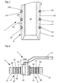
- Fig. 1 comprises a hose connection device 1, which is designed to connect at least one hose, at least one hollow connection section 2, which has in its interior a fluid flow opening 20 through which a fluid, in particular water, can flow.
- This connection section 2 is dimensioned and shaped so that a hose without connection adapter or the like can be plugged directly onto it from the outside.
- the connection section 2 has three circumferentially extending and substantially truncated cone-shaped outer wall sections 21, 22, 23 in a manner known per se in the longitudinal direction. At a longitudinally viewed rear end of each outer wall portion 21, 22, 23 is formed in each case a recess 210, 220, 230 from a larger outer diameter to a smaller outer diameter.
- the outer wall sections 21, 22, 23 face with others So words on a rib-like structuring.
- the frusto-conical shape of the outer wall sections 21, 22, 23 facilitates, in particular, the attachment of a hose onto the connection section 2.
- the recesses 210, 220, 230 cause the hose plugged onto the connection section 2 into adjacent regions of the outer wall sections 21, 22, 23 held with a larger outer diameter by frictional engagement and thus can be prefixed.
- the hose is additionally secured from the outside by means of a clamping device.
- the clamping device may be, for example, a hose clamp or clamping shells or the like clamping means.
- the connecting portion 2 has three longitudinally spaced apart, annular sealing elements 30, 31, 32, which are preferably made of a rubber-elastic material.
- the sealing elements 30, 31, 32 may alternatively be made of a material which has no rubber-elastic properties (for example PTFE).
- the connection section 2 also has three annular, circumferentially extending receiving grooves 24, 25, 26, which can be produced, for example, by cutting material removal, in particular by screwing into the outer wall sections 21, 22, 23. In each of the receiving grooves 24, 25, 26 each one of the sealing elements 30, 31, 32 is arranged.
- sealing elements 30, 31, 32 By providing the sealing elements 30, 31, 32, an additional way of sealing the arrangement is advantageously provided after the insertion of the hose, so that an improved protection against leaks is provided.
- the arrangement of Sealing elements 30, 31, 32 in the receiving grooves 24, 25, 26 can advantageously prevent slippage of the sealing elements 30, 31, 32 when attaching the hose to the connecting section 2.
- the hose connection device 1 may, for example, be formed integrally with a valve, not explicitly shown here, in particular an outlet valve. There is also the possibility that the hose connection device 1 comprises at least one connecting means, which is designed so that the hose connection device 1 can be detachably connected to such a valve.
- the connection means may be, for example, a screw connection means.
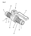
- a hose connection device 1 which is designed according to a second embodiment of the present invention.
- This hose connection device 1 is designed so that in each case a hose can be connected at opposite ends.
- this hose connection device 1 in other words, at least two hoses can be connected to one another.
- the hose connection device 1 has a first connection section 2 and a second connection section 2 ', both of which in turn are hollow and each have a fluid flow opening in their interior, through which a fluid can flow.
- the two connection sections 2, 2 ' are formed so that directly from each outside a hose without additional connection adapter or the like can be plugged.
- Each of the two connecting sections 2, 2 'in this exemplary embodiment has three outer wall sections 21, 22, 23, 21', 22 ', 23' which extend in the circumferential direction and have a substantially frusto-conical shape.
- each outer wall portion 21, 22, 23, 21 ', 22', 23 ' is - analogous to the hose connection device 1 according to the first embodiment - each formed a recess from a larger outer diameter to a smaller outer diameter.
- the truncated cone-like configuration of the outer wall sections 21, 22, 23, 21 ', 22', 23 ' makes it easier to attach the tubes to the connecting sections 2, 2'.
- the recesses result in a rib-like structuring of the connecting sections 2, 2, which causes the hoses, which are plugged onto the respective connecting sections 2, 2 ', to be adjacent to these regions of the outer wall sections 21, 22, 23, 21', 22 ', 23'.
- the clamping devices may be, for example, hose clamps or clamping shells or the like clamping means.
- each of the two connecting portions 2, 2 ' has three longitudinally spaced apart annularly formed sealing elements 30, 31, 32, 30', 31 ', 32' which are made in particular of a rubber-elastic material.
- the sealing elements 30, 31, 32, 30 ', 31', 32 ' may alternatively be made of a material which has no rubber-elastic properties (for example PTFE).
- Each of the two connecting sections 2, 2 ' has, seen in the longitudinal direction, three annular grooves extending in the circumferential direction, which are produced, for example, by cutting material removal, in particular by screwing into the outer wall sections 21, 22, 23, 21', 22 ', 23' can be.
- each of the receiving grooves in each case one of the sealing elements 30, 31, 32, 30 ', 31', 32 'is arranged.
- an additional sealing of the arrangement is advantageously created after the insertion of the tubes, so that an improved protection against leaks can be achieved.
- a shut-off device 4 is provided in this exemplary embodiment, which is designed such that a flow connection between the two connection sections 2, 2' can be selectively opened or closed by a user.
- the two connection sections 2, 2 ' are each connected by a sealed screw connection to a base body 40 of the obturator 4.
- the obturator 4, which in the present case is designed as a so-called ball valve, has a rotatable handling handle 41, by the actuation of which the flow connection between the two connection sections 2, 2 'can be selectively opened or closed.
- the hose connection device 1 according to Fig. 2 and 3 be formed without the obturator 4.
- the hose connection device 1 is then functionally a pure Hose connection device without the ability to interrupt the flow connection between the connected hoses by means of the obturator 4 can.
- the hose connection device 1 can also be designed, with or without a shut-off device 4, such that it has more than two connection sections 2, 2 'of the type explained above, to each of which a hose can be fastened.
- connection sections 2, 2 ' have no rib-like structuring on their outer sides and are thus made smooth.
- At least one sealing element 30, 31, 32, 30 ', 31', 32 ' is attached to the connecting sections 2, 2' formed in this way.
- the sealing elements 30, 31, 32, 30 ', 31', 32 'attached to the connection sections 2, 2' can not only improve the sealing in all the embodiments explained here, but also improve the build-up of a vacuum, manufacturing tolerances and inaccuracies both the terminal portions 2, 2 'and the hoses attached thereto and impurities of the fluid passing through (for example, by adhesive that could be used for sealing) prevent.
Applications Claiming Priority (1)
| Application Number | Priority Date | Filing Date | Title |
|---|---|---|---|
| DE102014112906.7A DE102014112906A1 (de) | 2014-09-08 | 2014-09-08 | Schlauchanschlussvorrichtung |
Publications (1)
| Publication Number | Publication Date |
|---|---|
| EP2998634A1 true EP2998634A1 (fr) | 2016-03-23 |
Family
ID=54007599
Family Applications (1)
| Application Number | Title | Priority Date | Filing Date |
|---|---|---|---|
| EP15182361.4A Withdrawn EP2998634A1 (fr) | 2014-09-08 | 2015-08-25 | Dispositif de raccord de tuyau |
Country Status (5)
| Country | Link |
|---|---|
| US (1) | US20160069489A1 (fr) |
| EP (1) | EP2998634A1 (fr) |
| CN (1) | CN105402526A (fr) |
| BR (1) | BR102015021557A2 (fr) |
| DE (1) | DE102014112906A1 (fr) |
Families Citing this family (3)
| Publication number | Priority date | Publication date | Assignee | Title |
|---|---|---|---|---|
| US10760716B1 (en) * | 2015-03-17 | 2020-09-01 | Mercury Plastics Llc | Leak-proof connection fitting |
| CN107448713A (zh) * | 2017-08-24 | 2017-12-08 | 海盐双赢管件制造有限公司 | 一种卡套式密封软管接头 |
| CN109798360A (zh) * | 2019-01-08 | 2019-05-24 | 苏州中宝复合材料股份有限公司 | 一种大型低温密封件及其制造方法 |
Citations (4)
| Publication number | Priority date | Publication date | Assignee | Title |
|---|---|---|---|---|
| FR2675880A1 (fr) * | 1991-04-26 | 1992-10-30 | Anoflex Flexibles | Embout a sertir pour tuyau flexible haute pression. |
| US5558375A (en) * | 1995-07-10 | 1996-09-24 | Deere & Company | Quick attach, reusable hose fittings |
| WO2006103432A1 (fr) * | 2005-03-29 | 2006-10-05 | Yorkshire Fittings Limited | Dispositif d’accouplement a un tube |
| US7628380B1 (en) * | 2005-10-11 | 2009-12-08 | Pureflex, Inc. | Self-compensating packing gland |
Family Cites Families (9)
| Publication number | Priority date | Publication date | Assignee | Title |
|---|---|---|---|---|
| WO1994019641A1 (fr) * | 1993-02-25 | 1994-09-01 | Abb District Heating Technology A/S | Tuyauterie calorifugee, methode de pose des tuyaux et moyens pour leur jonction |
| JP4178463B2 (ja) * | 2003-08-04 | 2008-11-12 | 豊田合成株式会社 | 樹脂製コネクタ |
| DE102005038476B4 (de) * | 2005-08-13 | 2020-05-28 | Eaton Fluid Power Gmbh | Vorrichtung und Verfahren zum Anschluss eines Hydraulikschlauchs an einen Anschlussnippel |
| US7806139B2 (en) * | 2006-01-20 | 2010-10-05 | Value Plastics, Inc. | Fluid conduit coupling assembly having male and female couplers with integral valves |
| US20080277002A1 (en) * | 2007-05-08 | 2008-11-13 | Paul Hendrixson | Coupler |
| CN201462052U (zh) * | 2009-04-27 | 2010-05-12 | 宁波华平金属制品有限公司 | 带有可更换接头的多功能球阀 |
| US20140326346A1 (en) * | 2011-12-07 | 2014-11-06 | Parker-Hannifin Corporation | Coupling |
| CN202708173U (zh) * | 2012-08-04 | 2013-01-30 | 洪宝玉 | 一种活接燃气阀 |
| US9212754B2 (en) * | 2013-03-12 | 2015-12-15 | A. Raymond Et Cie | Shape memory alloy valve |
-
2014
- 2014-09-08 DE DE102014112906.7A patent/DE102014112906A1/de active Pending
-
2015
- 2015-08-25 EP EP15182361.4A patent/EP2998634A1/fr not_active Withdrawn
- 2015-09-03 BR BR102015021557A patent/BR102015021557A2/pt not_active Application Discontinuation
- 2015-09-07 US US14/846,936 patent/US20160069489A1/en not_active Abandoned
- 2015-09-08 CN CN201510869166.1A patent/CN105402526A/zh active Pending
Patent Citations (4)
| Publication number | Priority date | Publication date | Assignee | Title |
|---|---|---|---|---|
| FR2675880A1 (fr) * | 1991-04-26 | 1992-10-30 | Anoflex Flexibles | Embout a sertir pour tuyau flexible haute pression. |
| US5558375A (en) * | 1995-07-10 | 1996-09-24 | Deere & Company | Quick attach, reusable hose fittings |
| WO2006103432A1 (fr) * | 2005-03-29 | 2006-10-05 | Yorkshire Fittings Limited | Dispositif d’accouplement a un tube |
| US7628380B1 (en) * | 2005-10-11 | 2009-12-08 | Pureflex, Inc. | Self-compensating packing gland |
Also Published As
| Publication number | Publication date |
|---|---|
| BR102015021557A2 (pt) | 2016-04-05 |
| US20160069489A1 (en) | 2016-03-10 |
| CN105402526A (zh) | 2016-03-16 |
| DE102014112906A1 (de) | 2016-03-10 |
Similar Documents
| Publication | Publication Date | Title |
|---|---|---|
| DE2358325C2 (de) | Vorrichtung für Rohrverbindungen | |
| DE2426234C2 (de) | Verbindungsstück aus Kunststoff oder Metall zum lösbaren Anschluß von Rohren mit unterschiedlichen Durchmessern | |
| DE2413748A1 (de) | Anschluss fuer druckmittelleitungen | |
| DE202004012714U1 (de) | Luer-Lock-Verbinder für medizinische Geräte | |
| DE2011409B2 (de) | Ventilschnellkupplung für zwei gas- oder flüssigkeitsführende Leitungen | |
| DE2404555A1 (de) | Schnellkupplung fuer schlaeuche und starre rohre | |
| DE7811524U1 (de) | Anordnung zur drehbaren verbindung eines saugschlauches mit einem kupplungsstueck bei einem staubsauger | |
| DE1600470A1 (de) | Austauschbares und umwandelbares Mehrzweckverbindungssystem fuer Rohrleitungen | |
| EP2998634A1 (fr) | Dispositif de raccord de tuyau | |
| DE1475706A1 (de) | Rohrfoermiges Verbindungsaggregat | |
| EP3322923A1 (fr) | Raccord de conduite sanitaire | |
| DE102013210922B4 (de) | Verbindungselement und Verbindungsanordnung | |
| DE3620869C2 (fr) | ||
| DE102010054978B4 (de) | Befestigungsanordnung zum Befestigen eines Steueraufsatzes an einem Gehäuse eines Wärmetauscherventils | |
| DE2930833A1 (de) | Klemmuffe | |
| EP2639487B1 (fr) | Raccord pour tubes avec bouchon | |
| DE2634721A1 (de) | Hydraulisches dreiwegeventil, insbesondere wasseranschluss fuer mund- und/ oder hautmassage- bzw. hautreinigungsduschen | |
| DE102011121089A1 (de) | Vorrichtung zum Halten und Abdichten eines Rohres | |
| DE4241817C2 (de) | Anschlußvorrichtung für Rohr- und/oder Schlauchleitungen | |
| DE10058967A1 (de) | Anschlussvorrichtung für Fluidleitungen | |
| DE1298797B (de) | Absperrventil | |
| DE202008010700U1 (de) | Verbindungs- und/oder Anschlusskörpervorrichtung zum Anbringen an einem Anschlussteil eines Arbeitskanals eines Endoskops | |
| DE3910644A1 (de) | Vorrichtung zum verbinden zweier teleskopartig zueinander angeordneter teile | |
| DE3818529C2 (fr) | ||
| CH682944A5 (de) | Rohr zum zugfesten Verbinden mit weiteren Rohren. |
Legal Events
| Date | Code | Title | Description |
|---|---|---|---|
| PUAI | Public reference made under article 153(3) epc to a published international application that has entered the european phase |
Free format text: ORIGINAL CODE: 0009012 |
|
| AK | Designated contracting states |
Kind code of ref document: A1 Designated state(s): AL AT BE BG CH CY CZ DE DK EE ES FI FR GB GR HR HU IE IS IT LI LT LU LV MC MK MT NL NO PL PT RO RS SE SI SK SM TR |
|
| AX | Request for extension of the european patent |
Extension state: BA ME |
|
| 17P | Request for examination filed |
Effective date: 20160923 |
|
| RBV | Designated contracting states (corrected) |
Designated state(s): AL AT BE BG CH CY CZ DE DK EE ES FI FR GB GR HR HU IE IS IT LI LT LU LV MC MK MT NL NO PL PT RO RS SE SI SK SM TR |
|
| STAA | Information on the status of an ep patent application or granted ep patent |
Free format text: STATUS: EXAMINATION IS IN PROGRESS |
|
| 17Q | First examination report despatched |
Effective date: 20181018 |
|
| STAA | Information on the status of an ep patent application or granted ep patent |
Free format text: STATUS: EXAMINATION IS IN PROGRESS |
|
| STAA | Information on the status of an ep patent application or granted ep patent |
Free format text: STATUS: THE APPLICATION IS DEEMED TO BE WITHDRAWN |
|
| 18D | Application deemed to be withdrawn |
Effective date: 20220301 |