EP2998634A1 - Hose connecting device - Google Patents
Hose connecting device Download PDFInfo
- Publication number
- EP2998634A1 EP2998634A1 EP15182361.4A EP15182361A EP2998634A1 EP 2998634 A1 EP2998634 A1 EP 2998634A1 EP 15182361 A EP15182361 A EP 15182361A EP 2998634 A1 EP2998634 A1 EP 2998634A1
- Authority
- EP
- European Patent Office
- Prior art keywords
- hose
- connection device
- sealing elements
- connection
- hose connection
- Prior art date
- Legal status (The legal status is an assumption and is not a legal conclusion. Google has not performed a legal analysis and makes no representation as to the accuracy of the status listed.)
- Withdrawn
Links
Images
Classifications
-
- F—MECHANICAL ENGINEERING; LIGHTING; HEATING; WEAPONS; BLASTING
- F16—ENGINEERING ELEMENTS AND UNITS; GENERAL MEASURES FOR PRODUCING AND MAINTAINING EFFECTIVE FUNCTIONING OF MACHINES OR INSTALLATIONS; THERMAL INSULATION IN GENERAL
- F16L—PIPES; JOINTS OR FITTINGS FOR PIPES; SUPPORTS FOR PIPES, CABLES OR PROTECTIVE TUBING; MEANS FOR THERMAL INSULATION IN GENERAL
- F16L25/00—Constructive types of pipe joints not provided for in groups F16L13/00 - F16L23/00 ; Details of pipe joints not otherwise provided for, e.g. electrically conducting or insulating means
- F16L25/0018—Abutment joints
-
- F—MECHANICAL ENGINEERING; LIGHTING; HEATING; WEAPONS; BLASTING
- F16—ENGINEERING ELEMENTS AND UNITS; GENERAL MEASURES FOR PRODUCING AND MAINTAINING EFFECTIVE FUNCTIONING OF MACHINES OR INSTALLATIONS; THERMAL INSULATION IN GENERAL
- F16L—PIPES; JOINTS OR FITTINGS FOR PIPES; SUPPORTS FOR PIPES, CABLES OR PROTECTIVE TUBING; MEANS FOR THERMAL INSULATION IN GENERAL
- F16L33/00—Arrangements for connecting hoses to rigid members; Rigid hose connectors, i.e. single members engaging both hoses
- F16L33/22—Arrangements for connecting hoses to rigid members; Rigid hose connectors, i.e. single members engaging both hoses with means not mentioned in the preceding groups for gripping the hose between inner and outer parts
- F16L33/227—Arrangements for connecting hoses to rigid members; Rigid hose connectors, i.e. single members engaging both hoses with means not mentioned in the preceding groups for gripping the hose between inner and outer parts the hose being introduced into or onto the connecting member and automatically locked
-
- F—MECHANICAL ENGINEERING; LIGHTING; HEATING; WEAPONS; BLASTING
- F16—ENGINEERING ELEMENTS AND UNITS; GENERAL MEASURES FOR PRODUCING AND MAINTAINING EFFECTIVE FUNCTIONING OF MACHINES OR INSTALLATIONS; THERMAL INSULATION IN GENERAL
- F16L—PIPES; JOINTS OR FITTINGS FOR PIPES; SUPPORTS FOR PIPES, CABLES OR PROTECTIVE TUBING; MEANS FOR THERMAL INSULATION IN GENERAL
- F16L29/00—Joints with fluid cut-off means
- F16L29/007—Joints with cut-off devices controlled separately
-
- F—MECHANICAL ENGINEERING; LIGHTING; HEATING; WEAPONS; BLASTING
- F16—ENGINEERING ELEMENTS AND UNITS; GENERAL MEASURES FOR PRODUCING AND MAINTAINING EFFECTIVE FUNCTIONING OF MACHINES OR INSTALLATIONS; THERMAL INSULATION IN GENERAL
- F16L—PIPES; JOINTS OR FITTINGS FOR PIPES; SUPPORTS FOR PIPES, CABLES OR PROTECTIVE TUBING; MEANS FOR THERMAL INSULATION IN GENERAL
- F16L31/00—Arrangements for connecting hoses to one another or to flexible sleeves
-
- F—MECHANICAL ENGINEERING; LIGHTING; HEATING; WEAPONS; BLASTING
- F16—ENGINEERING ELEMENTS AND UNITS; GENERAL MEASURES FOR PRODUCING AND MAINTAINING EFFECTIVE FUNCTIONING OF MACHINES OR INSTALLATIONS; THERMAL INSULATION IN GENERAL
- F16L—PIPES; JOINTS OR FITTINGS FOR PIPES; SUPPORTS FOR PIPES, CABLES OR PROTECTIVE TUBING; MEANS FOR THERMAL INSULATION IN GENERAL
- F16L33/00—Arrangements for connecting hoses to rigid members; Rigid hose connectors, i.e. single members engaging both hoses
- F16L33/18—Arrangements for connecting hoses to rigid members; Rigid hose connectors, i.e. single members engaging both hoses characterised by the use of additional sealing means
-
- F—MECHANICAL ENGINEERING; LIGHTING; HEATING; WEAPONS; BLASTING
- F16—ENGINEERING ELEMENTS AND UNITS; GENERAL MEASURES FOR PRODUCING AND MAINTAINING EFFECTIVE FUNCTIONING OF MACHINES OR INSTALLATIONS; THERMAL INSULATION IN GENERAL
- F16L—PIPES; JOINTS OR FITTINGS FOR PIPES; SUPPORTS FOR PIPES, CABLES OR PROTECTIVE TUBING; MEANS FOR THERMAL INSULATION IN GENERAL
- F16L33/00—Arrangements for connecting hoses to rigid members; Rigid hose connectors, i.e. single members engaging both hoses
- F16L33/30—Arrangements for connecting hoses to rigid members; Rigid hose connectors, i.e. single members engaging both hoses comprising parts inside the hoses only
-
- F—MECHANICAL ENGINEERING; LIGHTING; HEATING; WEAPONS; BLASTING
- F16—ENGINEERING ELEMENTS AND UNITS; GENERAL MEASURES FOR PRODUCING AND MAINTAINING EFFECTIVE FUNCTIONING OF MACHINES OR INSTALLATIONS; THERMAL INSULATION IN GENERAL
- F16L—PIPES; JOINTS OR FITTINGS FOR PIPES; SUPPORTS FOR PIPES, CABLES OR PROTECTIVE TUBING; MEANS FOR THERMAL INSULATION IN GENERAL
- F16L37/00—Couplings of the quick-acting type
- F16L37/02—Couplings of the quick-acting type in which the connection is maintained only by friction of the parts being joined
-
- F—MECHANICAL ENGINEERING; LIGHTING; HEATING; WEAPONS; BLASTING
- F16—ENGINEERING ELEMENTS AND UNITS; GENERAL MEASURES FOR PRODUCING AND MAINTAINING EFFECTIVE FUNCTIONING OF MACHINES OR INSTALLATIONS; THERMAL INSULATION IN GENERAL
- F16L—PIPES; JOINTS OR FITTINGS FOR PIPES; SUPPORTS FOR PIPES, CABLES OR PROTECTIVE TUBING; MEANS FOR THERMAL INSULATION IN GENERAL
- F16L37/00—Couplings of the quick-acting type
- F16L37/28—Couplings of the quick-acting type with fluid cut-off means
Definitions
- the present invention relates to a hose connection device for connecting at least one hose, comprising at least one hollow connection section, which has a fluid flow opening in its interior and is dimensioned and shaped such that a hose can be directly plugged onto the latter from the outside.
- Hose connection devices of the type mentioned are already known from the prior art in different embodiments.
- a hose without connection adapter or the like is attached directly to the connection section from the outside.
- the connecting portion may have on its outer side a rib structure.
- the hose is additionally secured from the outside by means of a clamping device on the connection section.
- a disadvantage of the known from the prior art hose connection devices is that in these unwanted fluid leakage can not always be reliably prevented. Furthermore, the buildup of a vacuum can not always be guaranteed. Thus, in use, under certain circumstances, the clamping device that secures the hose to the connection section, a little loose, so that the clamping force is reduced. As a result, although the hose is still held at the terminal portion, at least a small amount of the fluid may flow between an inner wall of the hose and an outer wall of the terminal portion.
- the present invention therefore has for its object to provide a hose connection device with an improved seal.
- a hose connection device is characterized in that at least one sealing element is attached to the connection section.
- at least one sealing element By providing at least one sealing element, an improved seal is provided.
- the at least one sealing member may further enhance vacuum build-up, compensate for manufacturing tolerances and inaccuracies of both the port portion and the hose, and prevent contamination of the fluid passing therethrough (for example, adhesive that could be used for sealing).
- a plurality of longitudinally spaced apart sealing elements are attached to the connecting portion.
- connection section comprises a number of annular, circumferentially extending receiving grooves corresponding to the number of sealing elements, one of the sealing elements being arranged in each of the receiving grooves.
- the arrangement of the sealing elements in these associated grooves can advantageously a Slippage of the sealing elements during insertion or removal of the hose can be prevented.
- connection portion viewed in the longitudinal direction may comprise a number of circumferentially extending, substantially truncated cone shaped outer wall portions, wherein preferably in each of these outer wall portions at least one of the receiving grooves is formed.
- a return from a larger outer diameter is formed toward a smaller outer diameter between adjacent frustoconical outer wall portions.
- the attachment of the hose can be simplified.
- the outer wall sections thus have a rib-like structuring.
- a frictional pre-fixing of the hose is effected at the connection portion.
- the at least one connection section it is also possible for the at least one connection section to have no rib-like structuring on its outer side and thus to be smooth.
- At least one sealing element can also be attached to the connection section formed in this way.
- the hose connection device has a first connection section which is dimensioned and shaped such that a first hose can be directly plugged onto it from outside, and at least one second connection section which is dimensioned and shaped such that on this from the outside, a second hose is directly plugged, has, wherein at each of the connecting portions at least one sealing element is attached.
- a first connection section which is dimensioned and shaped such that a first hose can be directly plugged onto it from outside
- at least one second connection section which is dimensioned and shaped such that on this from the outside, a second hose is directly plugged
- a plurality of longitudinally spaced apart sealing elements are attached to the connecting portions.
- each connection section comprises a number of sealing elements corresponding number of annular, circumferentially extending receiving grooves, wherein in each of the receiving grooves in each case one of the sealing elements is arranged.
- At least one of the terminal portions viewed in the longitudinal direction may comprise a number of circumferentially extending, substantially truncated cone shaped outer wall portions, wherein preferably in each of these outer wall portions at least one of the receiving grooves is formed.
- all connection sections of the hose connection device can be designed in this way. Between adjacent frusto-conically shaped outer wall sections, a recess is formed from a larger outer diameter to a smaller outer diameter, so that the attachment of the hose or the hoses is simplified and in the areas with a larger outer diameter, in which the connecting portions are formed like a rib, a frictional pre-fixing is possible.
- the connection sections it is also possible for the connection sections to have no rib-like structuring on their outer sides and thus to be smooth.
- At least one sealing element can also be attached to the connecting sections formed in this way.
- the sealing elements may advantageously be formed as sealing rings, which are preferably made of a rubber-elastic material.
- the sealing rings can also be made of a material which has no rubber-elastic properties (for example PTFE).
- connection sections can be advantageously connected by sealed screw with the obturator.
- the obturator may be a ball valve. This is characterized in particular by a robust mechanical structure. It also has a low flow resistance and can be opened and closed quickly.
- the hose connection device is formed integrally with a valve, in particular an outlet valve or a shut-off valve, or at least comprises a connecting means, by means of which it can be connected to a valve, in particular an outlet valve.
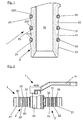
- Fig. 1 comprises a hose connection device 1, which is designed to connect at least one hose, at least one hollow connection section 2, which has in its interior a fluid flow opening 20 through which a fluid, in particular water, can flow.
- This connection section 2 is dimensioned and shaped so that a hose without connection adapter or the like can be plugged directly onto it from the outside.
- the connection section 2 has three circumferentially extending and substantially truncated cone-shaped outer wall sections 21, 22, 23 in a manner known per se in the longitudinal direction. At a longitudinally viewed rear end of each outer wall portion 21, 22, 23 is formed in each case a recess 210, 220, 230 from a larger outer diameter to a smaller outer diameter.
- the outer wall sections 21, 22, 23 face with others So words on a rib-like structuring.
- the frusto-conical shape of the outer wall sections 21, 22, 23 facilitates, in particular, the attachment of a hose onto the connection section 2.
- the recesses 210, 220, 230 cause the hose plugged onto the connection section 2 into adjacent regions of the outer wall sections 21, 22, 23 held with a larger outer diameter by frictional engagement and thus can be prefixed.
- the hose is additionally secured from the outside by means of a clamping device.
- the clamping device may be, for example, a hose clamp or clamping shells or the like clamping means.
- the connecting portion 2 has three longitudinally spaced apart, annular sealing elements 30, 31, 32, which are preferably made of a rubber-elastic material.
- the sealing elements 30, 31, 32 may alternatively be made of a material which has no rubber-elastic properties (for example PTFE).
- the connection section 2 also has three annular, circumferentially extending receiving grooves 24, 25, 26, which can be produced, for example, by cutting material removal, in particular by screwing into the outer wall sections 21, 22, 23. In each of the receiving grooves 24, 25, 26 each one of the sealing elements 30, 31, 32 is arranged.
- sealing elements 30, 31, 32 By providing the sealing elements 30, 31, 32, an additional way of sealing the arrangement is advantageously provided after the insertion of the hose, so that an improved protection against leaks is provided.
- the arrangement of Sealing elements 30, 31, 32 in the receiving grooves 24, 25, 26 can advantageously prevent slippage of the sealing elements 30, 31, 32 when attaching the hose to the connecting section 2.
- the hose connection device 1 may, for example, be formed integrally with a valve, not explicitly shown here, in particular an outlet valve. There is also the possibility that the hose connection device 1 comprises at least one connecting means, which is designed so that the hose connection device 1 can be detachably connected to such a valve.
- the connection means may be, for example, a screw connection means.
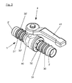
- a hose connection device 1 which is designed according to a second embodiment of the present invention.
- This hose connection device 1 is designed so that in each case a hose can be connected at opposite ends.
- this hose connection device 1 in other words, at least two hoses can be connected to one another.
- the hose connection device 1 has a first connection section 2 and a second connection section 2 ', both of which in turn are hollow and each have a fluid flow opening in their interior, through which a fluid can flow.
- the two connection sections 2, 2 ' are formed so that directly from each outside a hose without additional connection adapter or the like can be plugged.
- Each of the two connecting sections 2, 2 'in this exemplary embodiment has three outer wall sections 21, 22, 23, 21', 22 ', 23' which extend in the circumferential direction and have a substantially frusto-conical shape.
- each outer wall portion 21, 22, 23, 21 ', 22', 23 ' is - analogous to the hose connection device 1 according to the first embodiment - each formed a recess from a larger outer diameter to a smaller outer diameter.
- the truncated cone-like configuration of the outer wall sections 21, 22, 23, 21 ', 22', 23 ' makes it easier to attach the tubes to the connecting sections 2, 2'.
- the recesses result in a rib-like structuring of the connecting sections 2, 2, which causes the hoses, which are plugged onto the respective connecting sections 2, 2 ', to be adjacent to these regions of the outer wall sections 21, 22, 23, 21', 22 ', 23'.
- the clamping devices may be, for example, hose clamps or clamping shells or the like clamping means.
- each of the two connecting portions 2, 2 ' has three longitudinally spaced apart annularly formed sealing elements 30, 31, 32, 30', 31 ', 32' which are made in particular of a rubber-elastic material.
- the sealing elements 30, 31, 32, 30 ', 31', 32 ' may alternatively be made of a material which has no rubber-elastic properties (for example PTFE).
- Each of the two connecting sections 2, 2 ' has, seen in the longitudinal direction, three annular grooves extending in the circumferential direction, which are produced, for example, by cutting material removal, in particular by screwing into the outer wall sections 21, 22, 23, 21', 22 ', 23' can be.
- each of the receiving grooves in each case one of the sealing elements 30, 31, 32, 30 ', 31', 32 'is arranged.
- an additional sealing of the arrangement is advantageously created after the insertion of the tubes, so that an improved protection against leaks can be achieved.
- a shut-off device 4 is provided in this exemplary embodiment, which is designed such that a flow connection between the two connection sections 2, 2' can be selectively opened or closed by a user.
- the two connection sections 2, 2 ' are each connected by a sealed screw connection to a base body 40 of the obturator 4.
- the obturator 4, which in the present case is designed as a so-called ball valve, has a rotatable handling handle 41, by the actuation of which the flow connection between the two connection sections 2, 2 'can be selectively opened or closed.
- the hose connection device 1 according to Fig. 2 and 3 be formed without the obturator 4.
- the hose connection device 1 is then functionally a pure Hose connection device without the ability to interrupt the flow connection between the connected hoses by means of the obturator 4 can.
- the hose connection device 1 can also be designed, with or without a shut-off device 4, such that it has more than two connection sections 2, 2 'of the type explained above, to each of which a hose can be fastened.
- connection sections 2, 2 ' have no rib-like structuring on their outer sides and are thus made smooth.
- At least one sealing element 30, 31, 32, 30 ', 31', 32 ' is attached to the connecting sections 2, 2' formed in this way.
- the sealing elements 30, 31, 32, 30 ', 31', 32 'attached to the connection sections 2, 2' can not only improve the sealing in all the embodiments explained here, but also improve the build-up of a vacuum, manufacturing tolerances and inaccuracies both the terminal portions 2, 2 'and the hoses attached thereto and impurities of the fluid passing through (for example, by adhesive that could be used for sealing) prevent.
Abstract
Die Erfindung betrifft eine Schlauchanschlussvorrichtung (1) zum Anschluss mindestens eines Schlauchs, umfassend zumindest einen hohlen Anschlussabschnitt (2, 2'), der in seinem Inneren eine Fluidströmungsöffnung (20) aufweist und so dimensioniert und geformt ist, dass auf diesen von außen ein Schlauch unmittelbar aufsteckbar ist, wobei an dem Anschlussabschnitt (2) zumindest ein Dichtungselement (30, 31 , 32, 30', 31', 32') angebracht ist.The invention relates to a hose connection device (1) for connecting at least one hose, comprising at least one hollow connection section (2, 2 '), which has a fluid flow opening (20) in its interior and is dimensioned and shaped in such a way that from outside a hose is directly plugged, wherein at the connection portion (2) at least one sealing element (30, 31, 32, 30 ', 31', 32 ') is mounted.
Description
Die vorliegende Erfindung betrifft eine Schlauchanschlussvorrichtung zum Anschluss mindestens eines Schlauchs, umfassend zumindest einen hohlen Anschlussabschnitt, der in seinem Inneren eine Fluidströmungsöffnung aufweist und so dimensioniert und geformt ist, dass auf diesen von außen ein Schlauch unmittelbar aufsteckbar ist.The present invention relates to a hose connection device for connecting at least one hose, comprising at least one hollow connection section, which has a fluid flow opening in its interior and is dimensioned and shaped such that a hose can be directly plugged onto the latter from the outside.
Schlauchanschlussvorrichtungen der eingangs genannten Art sind aus dem Stand der Technik in unterschiedlichen Ausführungsformen bereits bekannt. Bei diesen Schlauchanschlussvorrichtungen wird auf den Anschlussabschnitt von außen ein Schlauch ohne Anschlussadapter oder dergleichen unmittelbar aufgesteckt. Um den Schlauch an dem Anschlussabschnitt gegen ein unerwünschtes Lösen zu sichern und einen Fluidaustritt aus dieser Anordnung zu verhindern, kann der Anschlussabschnitt an seiner Außenseite eine Rippenstruktur aufweisen. Der Schlauch wird zusätzlich von außen mittels einer Klemmvorrichtung an dem Anschlussabschnitt gesichert.Hose connection devices of the type mentioned are already known from the prior art in different embodiments. In these hose connection devices, a hose without connection adapter or the like is attached directly to the connection section from the outside. In order to secure the hose at the connecting portion against undesired loosening and prevent fluid leakage from this arrangement, the connecting portion may have on its outer side a rib structure. The hose is additionally secured from the outside by means of a clamping device on the connection section.
Ein Nachteil der aus dem Stand der Technik bekannten Schlauchanschlussvorrichtungen besteht darin, dass bei diesen ein unerwünschter Fluidaustritt nicht immer zuverlässig verhindert werden kann. Weiterhin kann der Aufbau eines Vakuums nicht immer gewährleistet werden. So kann sich im Gebrauch unter Umständen die Klemmvorrichtung, die den Schlauch an dem Anschlussabschnitt sichert, ein wenig lösen, so dass die Klemmkraft verringert wird. Dieses hat zur Folge, dass der Schlauch zwar immer noch an dem Anschlussabschnitt gehalten wird, aber zumindest eine geringe Menge des Fluids zwischen einer Innenwand des Schlauchs und einer Außenwand des Anschlussabschnitts fließen kann.A disadvantage of the known from the prior art hose connection devices is that in these unwanted fluid leakage can not always be reliably prevented. Furthermore, the buildup of a vacuum can not always be guaranteed. Thus, in use, under certain circumstances, the clamping device that secures the hose to the connection section, a little loose, so that the clamping force is reduced. As a result, although the hose is still held at the terminal portion, at least a small amount of the fluid may flow between an inner wall of the hose and an outer wall of the terminal portion.
Die vorliegende Erfindung macht es sich daher zur Aufgabe, eine Schlauchanschlussvorrichtung mit einer verbesserten Abdichtung zur Verfügung zu stellen.The present invention therefore has for its object to provide a hose connection device with an improved seal.
Die Lösung dieser Aufgabe liefert eine Schlauchanschlussvorrichtung der eingangs genannten Art mit den Merkmalen des kennzeichnenden Teils des Anspruchs 1. Die Unteransprüche betreffen vorteilhafte Weiterbildungen der Erfindung.The solution to this problem provides a hose connection device of the type mentioned above with the features of the characterizing part of claim 1. The dependent claims relate to advantageous developments of the invention.
Eine erfindungsgemäße Schlauchanschlussvorrichtung zeichnet sich dadurch aus, dass an dem Anschlussabschnitt zumindest ein Dichtungselement angebracht ist. Durch das Vorsehen zumindest eines Dichtungselements wird eine verbesserte Abdichtung geschaffen. Das mindestens eine Dichtungselement kann ferner den Aufbau eines Vakuums verbessern, Fertigungstoleranzen und -ungenauigkeiten sowohl des Anschlussabschnitts als auch des Schlauchs ausgleichen sowie Verunreinigungen des hindurchströmenden Fluids (zum Beispiel durch Klebstoff, der zur Abdichtung verwendet werden könnte) verhindern.A hose connection device according to the invention is characterized in that at least one sealing element is attached to the connection section. By providing at least one sealing element, an improved seal is provided. The at least one sealing member may further enhance vacuum build-up, compensate for manufacturing tolerances and inaccuracies of both the port portion and the hose, and prevent contamination of the fluid passing therethrough (for example, adhesive that could be used for sealing).
Um die Abdichtungswirkung weiter zu erhöhen, wird in einer bevorzugten Ausführungsform vorgeschlagen, dass an dem Anschlussabschnitt mehrere in Längsrichtung voneinander beabstandete Dichtungselemente angebracht sind.In order to further increase the sealing effect, it is proposed in a preferred embodiment that a plurality of longitudinally spaced apart sealing elements are attached to the connecting portion.
Um die Dichtungselemente sicher an dem Anschlussabschnitt zu halten, kann in einer besonders bevorzugten Ausführungsform vorgesehen sein, dass der Anschlussabschnitt eine der Anzahl der Dichtungselemente entsprechende Anzahl ringförmiger, sich in Umfangsrichtung erstreckender Aufnahmenuten umfasst, wobei in jeder der Aufnahmenuten jeweils eines der Dichtungselemente angeordnet ist. Durch die Anordnung der Dichtungselemente in diesen zugeordneten Aufnahmenuten kann in vorteilhafter Weise ein Verrutschen der Dichtungselemente beim Aufstecken oder Entfernen des Schlauchs verhindert werden. Grundsätzlich besteht auch die Möglichkeit, dass in den Aufnahmenuten jeweils mehrere Dichtungselemente angeordnet sind.In order to securely hold the sealing elements to the connection section, it may be provided in a particularly preferred embodiment that the connection section comprises a number of annular, circumferentially extending receiving grooves corresponding to the number of sealing elements, one of the sealing elements being arranged in each of the receiving grooves. The arrangement of the sealing elements in these associated grooves can advantageously a Slippage of the sealing elements during insertion or removal of the hose can be prevented. In principle, there is also the possibility that in each case a plurality of sealing elements are arranged in the receiving grooves.
Vorzugsweise kann der Anschlussabschnitt in Längsrichtung betrachtet eine Anzahl sich in Umfangsrichtung erstreckender, im Wesentlichen kegelstumpfartig geformter Außenwandabschnitte aufweisen, wobei vorzugsweise in jedem dieser Außenwandabschnitte mindestens eine der Aufnahmenuten ausgebildet ist. Dabei wird zwischen benachbarten kegelstumpfartig geformten Außenwandabschnitten ein Rücksprung von einem größeren Außendurchmesser hin zu einem geringeren Außendurchmesser gebildet. Dadurch kann das Aufstecken des Schlauches vereinfacht werden. Die Außenwandabschnitte weisen mit anderen Worten also eine rippenartige Strukturierung auf. Auf diese Weise wird eine reibschlüssige Vorfixierung des Schlauches an dem Anschlussabschnitt bewirkt. Grundsätzlich ist es auch möglich, dass der mindestens eine Anschlussabschnitt an seiner Außenseite keine rippenartige Strukturierung aufweist und somit glatt ausgebildet ist. An dem in dieser Weise ausgebildeten Anschlussabschnitt kann ebenfalls zumindest ein Dichtungselement angebracht werden.Preferably, the connection portion viewed in the longitudinal direction may comprise a number of circumferentially extending, substantially truncated cone shaped outer wall portions, wherein preferably in each of these outer wall portions at least one of the receiving grooves is formed. In this case, a return from a larger outer diameter is formed toward a smaller outer diameter between adjacent frustoconical outer wall portions. As a result, the attachment of the hose can be simplified. In other words, the outer wall sections thus have a rib-like structuring. In this way, a frictional pre-fixing of the hose is effected at the connection portion. In principle, it is also possible for the at least one connection section to have no rib-like structuring on its outer side and thus to be smooth. At least one sealing element can also be attached to the connection section formed in this way.
In einer bevorzugten Weiterbildung der Erfindung besteht die Möglichkeit, dass die Schlauchanschlussvorrichtung einen ersten Anschlussabschnitt, der so dimensioniert und geformt ist, dass auf diesen von außen ein erster Schlauch unmittelbar aufsteckbar ist, und zumindest einen zweiten Anschlussabschnitt, der so dimensioniert und geformt ist, dass auf diesen von außen ein zweiter Schlauch unmittelbar aufsteckbar ist, aufweist, wobei an jedem der Anschlussabschnitte zumindest ein Dichtungselement angebracht ist. Dadurch wird die Möglichkeit geschaffen, mindestens zwei Schläuche miteinander zu verbinden. Auf jeden der beiden Anschlussabschnitte wird bei der Montage jeweils ein Schlauch aufgesteckt und mit Hilfe mindestens einer Klemmvorrichtung gesichert. Dadurch, dass an jedem der Anschlussabschnitte zumindest ein Dichtungselement angebracht ist, wird die Anordnung in diesem Bereich zusätzlich abgedichtet.In a preferred embodiment of the invention, there is the possibility that the hose connection device has a first connection section which is dimensioned and shaped such that a first hose can be directly plugged onto it from outside, and at least one second connection section which is dimensioned and shaped such that on this from the outside, a second hose is directly plugged, has, wherein at each of the connecting portions at least one sealing element is attached. This creates the opportunity to connect at least two tubes together. On each of the two connection sections During assembly, a hose is attached in each case and secured by means of at least one clamping device. The fact that at least one sealing element is attached to each of the connecting portions, the assembly is additionally sealed in this area.
Um die Abdichtung der Anordnung nach der Anbringung der Schläuche weiter zu verbessern, wird in einer bevorzugten Ausführungsform vorgeschlagen, dass an den Anschlussabschnitten mehrere, in Längsrichtung voneinander beabstandete Dichtungselemente angebracht sind.In order to further improve the sealing of the assembly after the attachment of the hoses, it is proposed in a preferred embodiment that a plurality of longitudinally spaced apart sealing elements are attached to the connecting portions.
Für einen sicheren Halt der Dichtungselemente hat es sich als zweckmäßig erwiesen, dass jeder Anschlussabschnitt eine der Anzahl der Dichtungselemente entsprechende Anzahl ringförmiger, sich in Umfangsrichtung erstreckender Aufnahmenuten umfasst, wobei in jeder der Aufnahmenuten jeweils eines der Dichtungselemente angeordnet ist. Dadurch wird erreicht, dass ein unerwünschtes Verrutschen der Dichtungselemente beim Aufstecken oder Entfernen der Schläuche verhindert werden kann. Prinzipiell besteht auch die Möglichkeit, dass in den Aufnahmenuten jeweils mehrere Dichtungselemente angeordnet sind.For a secure hold of the sealing elements, it has proved to be expedient that each connection section comprises a number of sealing elements corresponding number of annular, circumferentially extending receiving grooves, wherein in each of the receiving grooves in each case one of the sealing elements is arranged. This ensures that undesired slippage of the sealing elements during insertion or removal of the tubes can be prevented. In principle, there is also the possibility that in each case a plurality of sealing elements are arranged in the receiving grooves.
Vorzugsweise kann zumindest einer der Anschlussabschnitte in Längsrichtung betrachtet eine Anzahl sich in Umfangsrichtung erstreckender, im Wesentlichen kegelstumpfartig geformter Außenwandabschnitte aufweisen, wobei vorzugsweise in jedem dieser Außenwandabschnitte mindestens eine der Aufnahmenuten ausgebildet ist. Vorteilhaft können alle Anschlussabschnitte der Schlauchanschlussvorrichtung in dieser Weise ausgebildet sein. Zwischen benachbarten kegelstumpfartig geformten Außenwandabschnitten wird ein Rücksprung von einem größeren Außendurchmesser zu einem geringeren Außendurchmesser gebildet, so dass das Aufstecken des Schlauches beziehungsweise der Schläuche vereinfacht wird und in den Bereichen mit größerem Außendurchmesser, in denen die Anschlussabschnitte rippenartig ausgebildet sind, eine reibschlüssige Vorfixierung ermöglicht wird. Grundsätzlich ist es auch möglich, dass die Anschlussabschnitte an ihren Außenseiten keine rippenartige Strukturierung aufweisen und somit glatt ausgebildet sind. An den in dieser Weise ausgebildeten Anschlussabschnitten kann ebenfalls zumindest ein Dichtungselement angebracht werden.Preferably, at least one of the terminal portions viewed in the longitudinal direction may comprise a number of circumferentially extending, substantially truncated cone shaped outer wall portions, wherein preferably in each of these outer wall portions at least one of the receiving grooves is formed. Advantageously, all connection sections of the hose connection device can be designed in this way. Between adjacent frusto-conically shaped outer wall sections, a recess is formed from a larger outer diameter to a smaller outer diameter, so that the attachment of the hose or the hoses is simplified and in the areas with a larger outer diameter, in which the connecting portions are formed like a rib, a frictional pre-fixing is possible. In principle, it is also possible for the connection sections to have no rib-like structuring on their outer sides and thus to be smooth. At least one sealing element can also be attached to the connecting sections formed in this way.
Die Dichtungselemente können vorteilhaft als Dichtungsringe ausgebildet sein, die vorzugsweise aus einem gummielastischen Werkstoff hergestellt sind. Die Dichtungsringe können auch aus einem Werkstoff hergestellt sein, der keine gummielastischen Eigenschaften aufweist (zum Beispiel PTFE).The sealing elements may advantageously be formed as sealing rings, which are preferably made of a rubber-elastic material. The sealing rings can also be made of a material which has no rubber-elastic properties (for example PTFE).
Um die Strömungsverbindung zwischen den Anschlussabschnitten selektiv öffnen und verschließen zu können, wird in einer bevorzugten Ausführungsform vorgeschlagen, dass zwischen den Anschlussabschnitten ein Absperrorgan angeordnet ist. Die Anschlussabschnitte können vorteilhaft durch abgedichtete Schraubverbindungen mit dem Absperrorgan verbunden sein. Vorzugsweise kann das Absperrorgan ein Kugelhahn sein. Dieser zeichnet sich insbesondere durch einen robusten mechanischen Aufbau aus. Er hat weiterhin einen geringen Strömungswiderstand und lässt sich schnell öffnen und schließen.In order to be able to selectively open and close the flow connection between the connection sections, it is proposed in a preferred embodiment that a shut-off element is arranged between the connection sections. The connection sections can be advantageously connected by sealed screw with the obturator. Preferably, the obturator may be a ball valve. This is characterized in particular by a robust mechanical structure. It also has a low flow resistance and can be opened and closed quickly.
In einer weiteren vorteilhaften Ausführungsform besteht die Möglichkeit, dass die Schlauchanschlussvorrichtung integral mit einem Ventil, insbesondere einem Auslaufventil oder einem Absperrventil, ausgebildet ist oder zumindest ein Verbindungsmittel umfasst, mittels dessen sie mit einem Ventil, insbesondere einem Auslaufventil, verbindbar ist.In a further advantageous embodiment, there is the possibility that the hose connection device is formed integrally with a valve, in particular an outlet valve or a shut-off valve, or at least comprises a connecting means, by means of which it can be connected to a valve, in particular an outlet valve.
Weitere Merkmale und Vorteile der vorliegenden Erfindung werden deutlich anhand der nachfolgenden Beschreibung bevorzugter Ausführungsbeispiele unter Bezugnahme auf die beiliegenden Abbildungen. Darin zeigen:
- Fig. 1
- einen Längsschnitt durch einen Teil einer Schlauchanschlussvorrichtung, die gemäß einem ersten Ausführungsbeispiel der vorliegenden Erfindung ausgeführt ist,
- Fig. 2
- eine Seitenansicht einer Schlauchanschlussvorrichtung, die gemäß einem zweiten Ausführungsbeispiel der vorliegenden Erfindung ausgeführt ist,
- Fig. 3
- eine perspektivische Ansicht der Schlauchanschlussvorrichtung gemäß
Fig. 2 .
- Fig. 1
- a longitudinal section through part of a hose connecting device, which is carried out according to a first embodiment of the present invention,
- Fig. 2
- a side view of a hose connecting device, which is designed according to a second embodiment of the present invention,
- Fig. 3
- a perspective view of the hose connecting device according to
Fig. 2 ,
Unter Bezugnahme auf
Um die Abdichtung der Anordnung nach dem Aufstecken und Befestigen des Schlauchs mittels der Klemmvorrichtung zu verbessern, weist der Anschlussabschnitt 2 drei in Längsrichtung voneinander beabstandete, ringförmig ausgebildete Dichtungselemente 30, 31, 32 auf, die vorzugsweise aus einem gummielastischen Werkstoff hergestellt sind. Die Dichtungselemente 30, 31, 32 können alternativ auch aus einem Werkstoff hergestellt sein, der keine gummielastischen Eigenschaften aufweist (zum Beispiel PTFE). Der Anschlussabschnitt 2 weist ferner drei ringförmige, sich in Umfangsrichtung erstreckende Aufnahmenuten 24, 25, 26 auf, die zum Beispiel durch spanenden Materialabtrag, insbesondere durch Eindrehen in die Außenwandabschnitte 21, 22, 23, hergestellt werden können. In jeder der Aufnahmenuten 24, 25, 26 ist jeweils eines der Dichtungselemente 30, 31, 32 angeordnet. Durch das Vorsehen der Dichtungselemente 30, 31, 32 wird in vorteilhafter Weise nach dem Aufstecken des Schlauchs eine zusätzliche Art der Abdichtung der Anordnung geschaffen, so dass ein verbesserter Schutz gegen Undichtigkeiten gegeben ist. Die Anordnung der Dichtungselemente 30, 31, 32 in den Aufnahmenuten 24, 25, 26 kann in vorteilhafter Weise ein Verrutschen der Dichtungselemente 30, 31, 32 beim Aufstecken des Schlauchs auf den Anschlussabschnitt 2 verhindern. Grundsätzlich besteht auch die Möglichkeit, dass in den Aufnahmenuten 24, 25, 26 jeweils mehrere Dichtungselemente 30, 31, 32 angeordnet sind.In order to improve the sealing of the assembly after attaching and securing the hose by means of the clamping device, the connecting
Die Schlauchanschlussvorrichtung 1 kann zum Beispiel integral mit einem hier nicht explizit dargestellten Ventil, insbesondere einem Auslaufventil, ausgebildet sein. Es besteht auch die Möglichkeit, dass die Schlauchanschlussvorrichtung 1 mindestens ein Verbindungsmittel umfasst, das so ausgebildet ist, dass die Schlauchanschlussvorrichtung 1 mit einem derartigen Ventil lösbar verbunden werden kann. Das Verbindungsmittel kann zum Beispiel ein Schraubverbindungsmittel sein.The hose connection device 1 may, for example, be formed integrally with a valve, not explicitly shown here, in particular an outlet valve. There is also the possibility that the hose connection device 1 comprises at least one connecting means, which is designed so that the hose connection device 1 can be detachably connected to such a valve. The connection means may be, for example, a screw connection means.
Unter Bezugnahme auf
Die Schlauchanschlussvorrichtung 1 weist einen ersten Anschlussabschnitt 2 und einen zweiten Anschlussabschnitt 2' auf, die beide wiederum hohl ausgebildet sind und in ihrem Inneren jeweils eine Fluidströmungsöffnung aufweisen, durch die ein Fluid hindurchströmen kann. Die beiden Anschlussabschnitte 2, 2' sind so ausgebildet, dass auf diese von außen jeweils ein Schlauch ohne zusätzlichen Anschlussadapter oder dergleichen unmittelbar aufgesteckt werden kann. Jeder der beiden Anschlussabschnitte 2, 2' weist in diesem Ausführungsbeispiel drei sich in Umfangsrichtung erstreckende, im Wesentlichen kegelstumpfartig geformte Außenwandabschnitte 21, 22, 23, 21', 22', 23' auf. An einem in Längsrichtung betrachtet hinteren Ende eines jeden Außenwandabschnitts 21, 22, 23, 21', 22', 23' ist - analog zu der Schlauchanschlussvorrichtung 1 gemäß dem ersten Ausführungsbeispiel - jeweils ein Rücksprung von einem größeren Außendurchmesser zu einem kleineren Außendurchmesser ausgebildet. Wie oben bereits erläutert, wird durch die kegelstumpfartige Ausgestaltung der Außenwandabschnitte 21, 22, 23, 21', 22', 23' das Aufstecken der Schläuche auf die Anschlussabschnitte 2, 2' vereinfacht. Durch die Rücksprünge wird eine rippenartige Strukturierung der Anschlussabschnitte 2, 2 erhalten, die bewirkt, dass die auf die jeweiligen Anschlussabschnitte 2, 2' aufgesteckten Schläuche in an diese angrenzenden Bereichen der Außenwandabschnitte 21, 22, 23, 21', 22', 23' mit größerem Außendurchmesser durch eine reibschlüssige Verbindung gehalten und dadurch vorfixiert werden können. Um die Schläuche an dem jeweiligen Anschlussabschnitt 2, 2' zu sichern und abzudichten, werden sie wiederum zusätzlich von außen mit Hilfe jeweils einer Klemmvorrichtung gesichert. Die Klemmvorrichtungen können zum Beispiel Schlauchschellen sein oder Klemmschalen oder dergleichen Klemmmittel aufweisen.The hose connection device 1 has a
Um die Abdichtung der Anordnung nach dem Aufstecken und Befestigen der Schläuche zu verbessern, weist jeder der beiden Anschlussabschnitte 2, 2' drei in Längsrichtung voneinander beabstandete, ringförmig ausgebildete Dichtungselemente 30, 31, 32, 30', 31', 32' auf, die insbesondere aus einem gummielastischen Werkstoff hergestellt sind. Die Dichtungselemente 30, 31, 32, 30', 31', 32' können alternativ auch aus einem Werkstoff hergestellt sein, der keine gummielastischen Eigenschaften aufweist (zum Beispiel PTFE). Jeder der beiden Anschlussabschnitte 2, 2' weist in Längsrichtung gesehen drei ringförmige, sich in Umfangsrichtung erstreckende Aufnahmenuten auf, die zum Beispiel durch spanenden Materialabtrag, insbesondere durch Eindrehen in die Außenwandabschnitte 21, 22, 23, 21', 22', 23' hergestellt werden können. In jeder der Aufnahmenuten ist jeweils eines der Dichtungselemente 30, 31, 32, 30', 31', 32' angeordnet. Durch das Vorsehen der Dichtungselemente 30, 31, 32, 30', 31', 32' wird nach dem Aufstecken der Schläuche in vorteilhafter Weise eine zusätzliche Abdichtung der Anordnung geschaffen, so dass ein verbesserter Schutz gegen Undichtigkeiten erreicht werden kann. Prinzipiell besteht auch die Möglichkeit, dass in den Aufnahmenuten jeweils mehrere Dichtungselemente 30, 31, 32, 30', 31', 32' angeordnet sind.In order to improve the sealing of the assembly after attaching and securing the hoses, each of the two connecting
Zwischen den beiden Anschlussabschnitten 2, 2' ist in diesem Ausführungsbeispiel ein Absperrorgan 4 vorgesehen, das so ausgebildet ist, dass eine Strömungsverbindung zwischen den beiden Anschlussabschnitten 2, 2' von einem Benutzer selektiv geöffnet beziehungsweise geschlossen werden kann. Die beiden Anschlussabschnitte 2, 2' sind jeweils durch eine abgedichtete Schraubverbindung mit einem Grundkörper 40 des Absperrorgans 4 verbunden. Das Absperrorgan 4, das vorliegend als so genannter Kugelhahn ausgebildet ist, weist einen drehbeweglichen Handhabungsgriff 41 auf, durch dessen Betätigung die Strömungsverbindung zwischen den beiden Anschlussabschnitten 2, 2' wahlweise geöffnet beziehungsweise geschlossen werden kann.Between the two
Gemäß einem weiteren, hier nicht explizit dargestellten Ausführungsbeispiel kann die Schlauchanschlussvorrichtung 1 gemäß
Die Schlauchanschlussvorrichtung 1 kann - mit oder ohne Absperrorgan 4 - auch so ausgebildet sein, dass sie mehr als zwei Anschlussabschnitte 2, 2' der oben erläuterten Art aufweist, an denen jeweils ein Schlauch befestigt werden kann.The hose connection device 1 can also be designed, with or without a shut-off
In alternativen Varianten der hier erläuterten Ausführungsbeispiele besteht auch die Möglichkeit, dass die Anschlussabschnitten 2, 2' an ihren Außenseiten keine rippenartigen Strukturierungen aufweisen und somit glatt ausgeführt sind. An den in dieser Weise ausgebildeten Anschlussabschnitten 2, 2' ist jeweils mindestens ein Dichtungselement 30, 31, 32, 30', 31', 32' angebracht.In alternative variants of the exemplary embodiments explained here, there is also the possibility that the
Die an den Anschlussabschnitten 2, 2' angebrachten Dichtungselemente 30, 31, 32, 30', 31', 32' können bei sämtlichen hier erläuterten Ausführungsbeispielen nicht nur die Abdichtung verbessern, sondern darüber hinaus auch den Aufbau eines Vakuums verbessern, Fertigungstoleranzen und -ungenauigkeiten sowohl der Anschlussabschnitte 2, 2' als auch der daran angebrachten Schläuche ausgleichen sowie Verunreinigungen des hindurchströmenden Fluids (zum Beispiel durch Klebstoff, der zur Abdichtung verwendet werden könnte) verhindern.The sealing
Claims (11)
Applications Claiming Priority (1)
| Application Number | Priority Date | Filing Date | Title |
|---|---|---|---|
| DE102014112906.7A DE102014112906A1 (en) | 2014-09-08 | 2014-09-08 | Hose connection device |
Publications (1)
| Publication Number | Publication Date |
|---|---|
| EP2998634A1 true EP2998634A1 (en) | 2016-03-23 |
Family
ID=54007599
Family Applications (1)
| Application Number | Title | Priority Date | Filing Date |
|---|---|---|---|
| EP15182361.4A Withdrawn EP2998634A1 (en) | 2014-09-08 | 2015-08-25 | Hose connecting device |
Country Status (5)
| Country | Link |
|---|---|
| US (1) | US20160069489A1 (en) |
| EP (1) | EP2998634A1 (en) |
| CN (1) | CN105402526A (en) |
| BR (1) | BR102015021557A2 (en) |
| DE (1) | DE102014112906A1 (en) |
Families Citing this family (3)
| Publication number | Priority date | Publication date | Assignee | Title |
|---|---|---|---|---|
| US10760716B1 (en) * | 2015-03-17 | 2020-09-01 | Mercury Plastics Llc | Leak-proof connection fitting |
| CN107448713A (en) * | 2017-08-24 | 2017-12-08 | 海盐双赢管件制造有限公司 | A kind of bite type seal tube joint |
| CN109798360A (en) * | 2019-01-08 | 2019-05-24 | 苏州中宝复合材料股份有限公司 | A kind of large-scale low-temperature sealing element and its manufacturing method |
Citations (4)
| Publication number | Priority date | Publication date | Assignee | Title |
|---|---|---|---|---|
| FR2675880A1 (en) * | 1991-04-26 | 1992-10-30 | Anoflex Flexibles | Crimped end fitting for high pressure hose |
| US5558375A (en) * | 1995-07-10 | 1996-09-24 | Deere & Company | Quick attach, reusable hose fittings |
| WO2006103432A1 (en) * | 2005-03-29 | 2006-10-05 | Yorkshire Fittings Limited | Tube coupling device |
| US7628380B1 (en) * | 2005-10-11 | 2009-12-08 | Pureflex, Inc. | Self-compensating packing gland |
Family Cites Families (9)
| Publication number | Priority date | Publication date | Assignee | Title |
|---|---|---|---|---|
| AU6139194A (en) * | 1993-02-25 | 1994-09-14 | Abb District Heating Technology A/S | Heat insulated pipe system, method of laying the pipes, and means for joining the pipes |
| JP4178463B2 (en) * | 2003-08-04 | 2008-11-12 | 豊田合成株式会社 | Resin connector |
| DE102005038476B4 (en) * | 2005-08-13 | 2020-05-28 | Eaton Fluid Power Gmbh | Device and method for connecting a hydraulic hose to a connection nipple |
| US7806139B2 (en) * | 2006-01-20 | 2010-10-05 | Value Plastics, Inc. | Fluid conduit coupling assembly having male and female couplers with integral valves |
| US20080277002A1 (en) * | 2007-05-08 | 2008-11-13 | Paul Hendrixson | Coupler |
| CN201462052U (en) * | 2009-04-27 | 2010-05-12 | 宁波华平金属制品有限公司 | Multifunctional ball valve with replaceable joint |
| US20140326346A1 (en) * | 2011-12-07 | 2014-11-06 | Parker-Hannifin Corporation | Coupling |
| CN202708173U (en) * | 2012-08-04 | 2013-01-30 | 洪宝玉 | Movably connected gas valve |
| US9212754B2 (en) * | 2013-03-12 | 2015-12-15 | A. Raymond Et Cie | Shape memory alloy valve |
-
2014
- 2014-09-08 DE DE102014112906.7A patent/DE102014112906A1/en active Pending
-
2015
- 2015-08-25 EP EP15182361.4A patent/EP2998634A1/en not_active Withdrawn
- 2015-09-03 BR BR102015021557A patent/BR102015021557A2/en not_active Application Discontinuation
- 2015-09-07 US US14/846,936 patent/US20160069489A1/en not_active Abandoned
- 2015-09-08 CN CN201510869166.1A patent/CN105402526A/en active Pending
Patent Citations (4)
| Publication number | Priority date | Publication date | Assignee | Title |
|---|---|---|---|---|
| FR2675880A1 (en) * | 1991-04-26 | 1992-10-30 | Anoflex Flexibles | Crimped end fitting for high pressure hose |
| US5558375A (en) * | 1995-07-10 | 1996-09-24 | Deere & Company | Quick attach, reusable hose fittings |
| WO2006103432A1 (en) * | 2005-03-29 | 2006-10-05 | Yorkshire Fittings Limited | Tube coupling device |
| US7628380B1 (en) * | 2005-10-11 | 2009-12-08 | Pureflex, Inc. | Self-compensating packing gland |
Also Published As
| Publication number | Publication date |
|---|---|
| DE102014112906A1 (en) | 2016-03-10 |
| US20160069489A1 (en) | 2016-03-10 |
| CN105402526A (en) | 2016-03-16 |
| BR102015021557A2 (en) | 2016-04-05 |
Similar Documents
| Publication | Publication Date | Title |
|---|---|---|
| DE2358325C2 (en) | Device for pipe connections | |
| DE2426234C2 (en) | Connector made of plastic or metal for the detachable connection of pipes with different diameters | |
| DE2413748A1 (en) | CONNECTION FOR PRESSURE MEDIUM PIPES | |
| DE202004012714U1 (en) | Luer lock connector for medical devices | |
| DE2431516B2 (en) | Device for dispensing fluids | |
| DE2011409B2 (en) | Quick-release valve coupling for two gas or liquid lines | |
| DE2404555A1 (en) | QUICK COUPLING FOR HOSES AND RIGID PIPES | |
| DE7811524U1 (en) | ARRANGEMENT FOR THE ROTATABLE CONNECTION OF A SUCTION HOSE WITH A COUPLING PIECE ON A VACUUM CLEANER | |
| DE1600470A1 (en) | Interchangeable and convertible multipurpose connection system for pipelines | |
| EP2998634A1 (en) | Hose connecting device | |
| DE1475706A1 (en) | Tubular connection unit | |
| EP3322923B1 (en) | Sanitary line attachment | |
| DE3620869C2 (en) | ||
| DE102010054978B4 (en) | Fastening arrangement for attaching a control attachment to a housing of a heat exchanger valve | |
| DE2930833A1 (en) | CLAMP SLEEVE | |
| EP2639487B1 (en) | Pipe coupling with end cap | |
| DE102011121089A1 (en) | Device for supporting and sealing pipe in pipe outlet or fitting, has mounting sleeve which overlaps and corresponds to nut in screwing or positive-locking direction and enables freewheel in opposite direction | |
| DE4241817C2 (en) | Connection device for pipe and / or hose lines | |
| DE10058967A1 (en) | Pipe connector comprises sleeve made up of two rings with inwardly-facing teeth, clamping arms separated by longitudinal slits being attached to each ring and arms on one ring fitting between arms on other | |
| DE1298797B (en) | Shut-off valve | |
| DE202008010700U1 (en) | Connecting and / or connecting body device for attachment to a connection part of a working channel of an endoscope | |
| DE3910644A1 (en) | Device for connecting two parts which are arranged telescopically with respect to one another | |
| DE3818529C2 (en) | ||
| CH682944A5 (en) | Tube for tight connection with other pipes. | |
| DE102018128721A1 (en) | Fluid channel separating device and valve assembly with fluid channel separating device |
Legal Events
| Date | Code | Title | Description |
|---|---|---|---|
| PUAI | Public reference made under article 153(3) epc to a published international application that has entered the european phase |
Free format text: ORIGINAL CODE: 0009012 |
|
| AK | Designated contracting states |
Kind code of ref document: A1 Designated state(s): AL AT BE BG CH CY CZ DE DK EE ES FI FR GB GR HR HU IE IS IT LI LT LU LV MC MK MT NL NO PL PT RO RS SE SI SK SM TR |
|
| AX | Request for extension of the european patent |
Extension state: BA ME |
|
| 17P | Request for examination filed |
Effective date: 20160923 |
|
| RBV | Designated contracting states (corrected) |
Designated state(s): AL AT BE BG CH CY CZ DE DK EE ES FI FR GB GR HR HU IE IS IT LI LT LU LV MC MK MT NL NO PL PT RO RS SE SI SK SM TR |
|
| STAA | Information on the status of an ep patent application or granted ep patent |
Free format text: STATUS: EXAMINATION IS IN PROGRESS |
|
| 17Q | First examination report despatched |
Effective date: 20181018 |
|
| STAA | Information on the status of an ep patent application or granted ep patent |
Free format text: STATUS: EXAMINATION IS IN PROGRESS |
|
| STAA | Information on the status of an ep patent application or granted ep patent |
Free format text: STATUS: THE APPLICATION IS DEEMED TO BE WITHDRAWN |
|
| 18D | Application deemed to be withdrawn |
Effective date: 20220301 |