EP2995489B1 - Transmission unit, power transmission system and vehicle comprising the same - Google Patents
Transmission unit, power transmission system and vehicle comprising the same Download PDFInfo
- Publication number
- EP2995489B1 EP2995489B1 EP15158701.1A EP15158701A EP2995489B1 EP 2995489 B1 EP2995489 B1 EP 2995489B1 EP 15158701 A EP15158701 A EP 15158701A EP 2995489 B1 EP2995489 B1 EP 2995489B1
- Authority
- EP
- European Patent Office
- Prior art keywords
- gear
- power
- motor
- shaft
- synchronizer
- Prior art date
- Legal status (The legal status is an assumption and is not a legal conclusion. Google has not performed a legal analysis and makes no representation as to the accuracy of the status listed.)
- Active
Links
Images


Classifications
-
- F—MECHANICAL ENGINEERING; LIGHTING; HEATING; WEAPONS; BLASTING
- F16—ENGINEERING ELEMENTS AND UNITS; GENERAL MEASURES FOR PRODUCING AND MAINTAINING EFFECTIVE FUNCTIONING OF MACHINES OR INSTALLATIONS; THERMAL INSULATION IN GENERAL
- F16H—GEARING
- F16H3/00—Toothed gearings for conveying rotary motion with variable gear ratio or for reversing rotary motion
- F16H3/006—Toothed gearings for conveying rotary motion with variable gear ratio or for reversing rotary motion power being selectively transmitted by either one of the parallel flow paths
-
- B—PERFORMING OPERATIONS; TRANSPORTING
- B60—VEHICLES IN GENERAL
- B60K—ARRANGEMENT OR MOUNTING OF PROPULSION UNITS OR OF TRANSMISSIONS IN VEHICLES; ARRANGEMENT OR MOUNTING OF PLURAL DIVERSE PRIME-MOVERS IN VEHICLES; AUXILIARY DRIVES FOR VEHICLES; INSTRUMENTATION OR DASHBOARDS FOR VEHICLES; ARRANGEMENTS IN CONNECTION WITH COOLING, AIR INTAKE, GAS EXHAUST OR FUEL SUPPLY OF PROPULSION UNITS IN VEHICLES
- B60K17/00—Arrangement or mounting of transmissions in vehicles
- B60K17/04—Arrangement or mounting of transmissions in vehicles characterised by arrangement, location, or kind of gearing
- B60K17/16—Arrangement or mounting of transmissions in vehicles characterised by arrangement, location, or kind of gearing of differential gearing
- B60K17/165—Arrangement or mounting of transmissions in vehicles characterised by arrangement, location, or kind of gearing of differential gearing provided between independent half axles
-
- B—PERFORMING OPERATIONS; TRANSPORTING
- B60—VEHICLES IN GENERAL
- B60K—ARRANGEMENT OR MOUNTING OF PROPULSION UNITS OR OF TRANSMISSIONS IN VEHICLES; ARRANGEMENT OR MOUNTING OF PLURAL DIVERSE PRIME-MOVERS IN VEHICLES; AUXILIARY DRIVES FOR VEHICLES; INSTRUMENTATION OR DASHBOARDS FOR VEHICLES; ARRANGEMENTS IN CONNECTION WITH COOLING, AIR INTAKE, GAS EXHAUST OR FUEL SUPPLY OF PROPULSION UNITS IN VEHICLES
- B60K17/00—Arrangement or mounting of transmissions in vehicles
- B60K17/34—Arrangement or mounting of transmissions in vehicles for driving both front and rear wheels, e.g. four wheel drive vehicles
- B60K17/356—Arrangement or mounting of transmissions in vehicles for driving both front and rear wheels, e.g. four wheel drive vehicles having fluid or electric motor, for driving one or more wheels
-
- B—PERFORMING OPERATIONS; TRANSPORTING
- B60—VEHICLES IN GENERAL
- B60K—ARRANGEMENT OR MOUNTING OF PROPULSION UNITS OR OF TRANSMISSIONS IN VEHICLES; ARRANGEMENT OR MOUNTING OF PLURAL DIVERSE PRIME-MOVERS IN VEHICLES; AUXILIARY DRIVES FOR VEHICLES; INSTRUMENTATION OR DASHBOARDS FOR VEHICLES; ARRANGEMENTS IN CONNECTION WITH COOLING, AIR INTAKE, GAS EXHAUST OR FUEL SUPPLY OF PROPULSION UNITS IN VEHICLES
- B60K6/00—Arrangement or mounting of plural diverse prime-movers for mutual or common propulsion, e.g. hybrid propulsion systems comprising electric motors and internal combustion engines ; Control systems therefor, i.e. systems controlling two or more prime movers, or controlling one of these prime movers and any of the transmission, drive or drive units Informative references: mechanical gearings with secondary electric drive F16H3/72; arrangements for handling mechanical energy structurally associated with the dynamo-electric machine H02K7/00; machines comprising structurally interrelated motor and generator parts H02K51/00; dynamo-electric machines not otherwise provided for in H02K see H02K99/00
- B60K6/20—Arrangement or mounting of plural diverse prime-movers for mutual or common propulsion, e.g. hybrid propulsion systems comprising electric motors and internal combustion engines ; Control systems therefor, i.e. systems controlling two or more prime movers, or controlling one of these prime movers and any of the transmission, drive or drive units Informative references: mechanical gearings with secondary electric drive F16H3/72; arrangements for handling mechanical energy structurally associated with the dynamo-electric machine H02K7/00; machines comprising structurally interrelated motor and generator parts H02K51/00; dynamo-electric machines not otherwise provided for in H02K see H02K99/00 the prime-movers consisting of electric motors and internal combustion engines, e.g. HEVs
- B60K6/42—Arrangement or mounting of plural diverse prime-movers for mutual or common propulsion, e.g. hybrid propulsion systems comprising electric motors and internal combustion engines ; Control systems therefor, i.e. systems controlling two or more prime movers, or controlling one of these prime movers and any of the transmission, drive or drive units Informative references: mechanical gearings with secondary electric drive F16H3/72; arrangements for handling mechanical energy structurally associated with the dynamo-electric machine H02K7/00; machines comprising structurally interrelated motor and generator parts H02K51/00; dynamo-electric machines not otherwise provided for in H02K see H02K99/00 the prime-movers consisting of electric motors and internal combustion engines, e.g. HEVs characterised by the architecture of the hybrid electric vehicle
- B60K6/44—Series-parallel type
- B60K6/442—Series-parallel switching type
-
- B—PERFORMING OPERATIONS; TRANSPORTING
- B60—VEHICLES IN GENERAL
- B60K—ARRANGEMENT OR MOUNTING OF PROPULSION UNITS OR OF TRANSMISSIONS IN VEHICLES; ARRANGEMENT OR MOUNTING OF PLURAL DIVERSE PRIME-MOVERS IN VEHICLES; AUXILIARY DRIVES FOR VEHICLES; INSTRUMENTATION OR DASHBOARDS FOR VEHICLES; ARRANGEMENTS IN CONNECTION WITH COOLING, AIR INTAKE, GAS EXHAUST OR FUEL SUPPLY OF PROPULSION UNITS IN VEHICLES
- B60K6/00—Arrangement or mounting of plural diverse prime-movers for mutual or common propulsion, e.g. hybrid propulsion systems comprising electric motors and internal combustion engines ; Control systems therefor, i.e. systems controlling two or more prime movers, or controlling one of these prime movers and any of the transmission, drive or drive units Informative references: mechanical gearings with secondary electric drive F16H3/72; arrangements for handling mechanical energy structurally associated with the dynamo-electric machine H02K7/00; machines comprising structurally interrelated motor and generator parts H02K51/00; dynamo-electric machines not otherwise provided for in H02K see H02K99/00
- B60K6/20—Arrangement or mounting of plural diverse prime-movers for mutual or common propulsion, e.g. hybrid propulsion systems comprising electric motors and internal combustion engines ; Control systems therefor, i.e. systems controlling two or more prime movers, or controlling one of these prime movers and any of the transmission, drive or drive units Informative references: mechanical gearings with secondary electric drive F16H3/72; arrangements for handling mechanical energy structurally associated with the dynamo-electric machine H02K7/00; machines comprising structurally interrelated motor and generator parts H02K51/00; dynamo-electric machines not otherwise provided for in H02K see H02K99/00 the prime-movers consisting of electric motors and internal combustion engines, e.g. HEVs
- B60K6/50—Architecture of the driveline characterised by arrangement or kind of transmission units
- B60K6/52—Driving a plurality of drive axles, e.g. four-wheel drive
-
- B—PERFORMING OPERATIONS; TRANSPORTING
- B60—VEHICLES IN GENERAL
- B60K—ARRANGEMENT OR MOUNTING OF PROPULSION UNITS OR OF TRANSMISSIONS IN VEHICLES; ARRANGEMENT OR MOUNTING OF PLURAL DIVERSE PRIME-MOVERS IN VEHICLES; AUXILIARY DRIVES FOR VEHICLES; INSTRUMENTATION OR DASHBOARDS FOR VEHICLES; ARRANGEMENTS IN CONNECTION WITH COOLING, AIR INTAKE, GAS EXHAUST OR FUEL SUPPLY OF PROPULSION UNITS IN VEHICLES
- B60K6/00—Arrangement or mounting of plural diverse prime-movers for mutual or common propulsion, e.g. hybrid propulsion systems comprising electric motors and internal combustion engines ; Control systems therefor, i.e. systems controlling two or more prime movers, or controlling one of these prime movers and any of the transmission, drive or drive units Informative references: mechanical gearings with secondary electric drive F16H3/72; arrangements for handling mechanical energy structurally associated with the dynamo-electric machine H02K7/00; machines comprising structurally interrelated motor and generator parts H02K51/00; dynamo-electric machines not otherwise provided for in H02K see H02K99/00
- B60K6/20—Arrangement or mounting of plural diverse prime-movers for mutual or common propulsion, e.g. hybrid propulsion systems comprising electric motors and internal combustion engines ; Control systems therefor, i.e. systems controlling two or more prime movers, or controlling one of these prime movers and any of the transmission, drive or drive units Informative references: mechanical gearings with secondary electric drive F16H3/72; arrangements for handling mechanical energy structurally associated with the dynamo-electric machine H02K7/00; machines comprising structurally interrelated motor and generator parts H02K51/00; dynamo-electric machines not otherwise provided for in H02K see H02K99/00 the prime-movers consisting of electric motors and internal combustion engines, e.g. HEVs
- B60K6/50—Architecture of the driveline characterised by arrangement or kind of transmission units
- B60K6/54—Transmission for changing ratio
- B60K6/547—Transmission for changing ratio the transmission being a stepped gearing
-
- B—PERFORMING OPERATIONS; TRANSPORTING
- B60—VEHICLES IN GENERAL
- B60K—ARRANGEMENT OR MOUNTING OF PROPULSION UNITS OR OF TRANSMISSIONS IN VEHICLES; ARRANGEMENT OR MOUNTING OF PLURAL DIVERSE PRIME-MOVERS IN VEHICLES; AUXILIARY DRIVES FOR VEHICLES; INSTRUMENTATION OR DASHBOARDS FOR VEHICLES; ARRANGEMENTS IN CONNECTION WITH COOLING, AIR INTAKE, GAS EXHAUST OR FUEL SUPPLY OF PROPULSION UNITS IN VEHICLES
- B60K7/00—Disposition of motor in, or adjacent to, traction wheel
- B60K7/0007—Disposition of motor in, or adjacent to, traction wheel the motor being electric
-
- F—MECHANICAL ENGINEERING; LIGHTING; HEATING; WEAPONS; BLASTING
- F16—ENGINEERING ELEMENTS AND UNITS; GENERAL MEASURES FOR PRODUCING AND MAINTAINING EFFECTIVE FUNCTIONING OF MACHINES OR INSTALLATIONS; THERMAL INSULATION IN GENERAL
- F16H—GEARING
- F16H3/00—Toothed gearings for conveying rotary motion with variable gear ratio or for reversing rotary motion
- F16H3/02—Toothed gearings for conveying rotary motion with variable gear ratio or for reversing rotary motion without gears having orbital motion
- F16H3/08—Toothed gearings for conveying rotary motion with variable gear ratio or for reversing rotary motion without gears having orbital motion exclusively or essentially with continuously meshing gears, that can be disengaged from their shafts
- F16H3/087—Toothed gearings for conveying rotary motion with variable gear ratio or for reversing rotary motion without gears having orbital motion exclusively or essentially with continuously meshing gears, that can be disengaged from their shafts characterised by the disposition of the gears
- F16H3/093—Toothed gearings for conveying rotary motion with variable gear ratio or for reversing rotary motion without gears having orbital motion exclusively or essentially with continuously meshing gears, that can be disengaged from their shafts characterised by the disposition of the gears with two or more countershafts
-
- B—PERFORMING OPERATIONS; TRANSPORTING
- B60—VEHICLES IN GENERAL
- B60K—ARRANGEMENT OR MOUNTING OF PROPULSION UNITS OR OF TRANSMISSIONS IN VEHICLES; ARRANGEMENT OR MOUNTING OF PLURAL DIVERSE PRIME-MOVERS IN VEHICLES; AUXILIARY DRIVES FOR VEHICLES; INSTRUMENTATION OR DASHBOARDS FOR VEHICLES; ARRANGEMENTS IN CONNECTION WITH COOLING, AIR INTAKE, GAS EXHAUST OR FUEL SUPPLY OF PROPULSION UNITS IN VEHICLES
- B60K7/00—Disposition of motor in, or adjacent to, traction wheel
- B60K2007/0046—Disposition of motor in, or adjacent to, traction wheel the motor moving together with the vehicle body, i.e. moving independently from the wheel axle
-
- B—PERFORMING OPERATIONS; TRANSPORTING
- B60—VEHICLES IN GENERAL
- B60K—ARRANGEMENT OR MOUNTING OF PROPULSION UNITS OR OF TRANSMISSIONS IN VEHICLES; ARRANGEMENT OR MOUNTING OF PLURAL DIVERSE PRIME-MOVERS IN VEHICLES; AUXILIARY DRIVES FOR VEHICLES; INSTRUMENTATION OR DASHBOARDS FOR VEHICLES; ARRANGEMENTS IN CONNECTION WITH COOLING, AIR INTAKE, GAS EXHAUST OR FUEL SUPPLY OF PROPULSION UNITS IN VEHICLES
- B60K7/00—Disposition of motor in, or adjacent to, traction wheel
- B60K2007/0061—Disposition of motor in, or adjacent to, traction wheel the motor axle being parallel to the wheel axle
-
- F—MECHANICAL ENGINEERING; LIGHTING; HEATING; WEAPONS; BLASTING
- F16—ENGINEERING ELEMENTS AND UNITS; GENERAL MEASURES FOR PRODUCING AND MAINTAINING EFFECTIVE FUNCTIONING OF MACHINES OR INSTALLATIONS; THERMAL INSULATION IN GENERAL
- F16H—GEARING
- F16H3/00—Toothed gearings for conveying rotary motion with variable gear ratio or for reversing rotary motion
- F16H3/02—Toothed gearings for conveying rotary motion with variable gear ratio or for reversing rotary motion without gears having orbital motion
- F16H3/08—Toothed gearings for conveying rotary motion with variable gear ratio or for reversing rotary motion without gears having orbital motion exclusively or essentially with continuously meshing gears, that can be disengaged from their shafts
- F16H2003/0807—Toothed gearings for conveying rotary motion with variable gear ratio or for reversing rotary motion without gears having orbital motion exclusively or essentially with continuously meshing gears, that can be disengaged from their shafts with gear ratios in which the power is transferred by axially coupling idle gears
-
- F—MECHANICAL ENGINEERING; LIGHTING; HEATING; WEAPONS; BLASTING
- F16—ENGINEERING ELEMENTS AND UNITS; GENERAL MEASURES FOR PRODUCING AND MAINTAINING EFFECTIVE FUNCTIONING OF MACHINES OR INSTALLATIONS; THERMAL INSULATION IN GENERAL
- F16H—GEARING
- F16H3/00—Toothed gearings for conveying rotary motion with variable gear ratio or for reversing rotary motion
- F16H3/02—Toothed gearings for conveying rotary motion with variable gear ratio or for reversing rotary motion without gears having orbital motion
- F16H3/08—Toothed gearings for conveying rotary motion with variable gear ratio or for reversing rotary motion without gears having orbital motion exclusively or essentially with continuously meshing gears, that can be disengaged from their shafts
- F16H2003/0822—Toothed gearings for conveying rotary motion with variable gear ratio or for reversing rotary motion without gears having orbital motion exclusively or essentially with continuously meshing gears, that can be disengaged from their shafts characterised by the arrangement of at least one reverse gear
-
- F—MECHANICAL ENGINEERING; LIGHTING; HEATING; WEAPONS; BLASTING
- F16—ENGINEERING ELEMENTS AND UNITS; GENERAL MEASURES FOR PRODUCING AND MAINTAINING EFFECTIVE FUNCTIONING OF MACHINES OR INSTALLATIONS; THERMAL INSULATION IN GENERAL
- F16H—GEARING
- F16H3/00—Toothed gearings for conveying rotary motion with variable gear ratio or for reversing rotary motion
- F16H3/02—Toothed gearings for conveying rotary motion with variable gear ratio or for reversing rotary motion without gears having orbital motion
- F16H3/08—Toothed gearings for conveying rotary motion with variable gear ratio or for reversing rotary motion without gears having orbital motion exclusively or essentially with continuously meshing gears, that can be disengaged from their shafts
- F16H3/087—Toothed gearings for conveying rotary motion with variable gear ratio or for reversing rotary motion without gears having orbital motion exclusively or essentially with continuously meshing gears, that can be disengaged from their shafts characterised by the disposition of the gears
- F16H3/093—Toothed gearings for conveying rotary motion with variable gear ratio or for reversing rotary motion without gears having orbital motion exclusively or essentially with continuously meshing gears, that can be disengaged from their shafts characterised by the disposition of the gears with two or more countershafts
- F16H2003/0931—Toothed gearings for conveying rotary motion with variable gear ratio or for reversing rotary motion without gears having orbital motion exclusively or essentially with continuously meshing gears, that can be disengaged from their shafts characterised by the disposition of the gears with two or more countershafts each countershaft having an output gear meshing with a single common gear on the output shaft
-
- F—MECHANICAL ENGINEERING; LIGHTING; HEATING; WEAPONS; BLASTING
- F16—ENGINEERING ELEMENTS AND UNITS; GENERAL MEASURES FOR PRODUCING AND MAINTAINING EFFECTIVE FUNCTIONING OF MACHINES OR INSTALLATIONS; THERMAL INSULATION IN GENERAL
- F16H—GEARING
- F16H2200/00—Transmissions for multiple ratios
- F16H2200/003—Transmissions for multiple ratios characterised by the number of forward speeds
- F16H2200/0056—Transmissions for multiple ratios characterised by the number of forward speeds the gear ratios comprising seven forward speeds
-
- Y—GENERAL TAGGING OF NEW TECHNOLOGICAL DEVELOPMENTS; GENERAL TAGGING OF CROSS-SECTIONAL TECHNOLOGIES SPANNING OVER SEVERAL SECTIONS OF THE IPC; TECHNICAL SUBJECTS COVERED BY FORMER USPC CROSS-REFERENCE ART COLLECTIONS [XRACs] AND DIGESTS
- Y02—TECHNOLOGIES OR APPLICATIONS FOR MITIGATION OR ADAPTATION AGAINST CLIMATE CHANGE
- Y02T—CLIMATE CHANGE MITIGATION TECHNOLOGIES RELATED TO TRANSPORTATION
- Y02T10/00—Road transport of goods or passengers
- Y02T10/60—Other road transportation technologies with climate change mitigation effect
- Y02T10/62—Hybrid vehicles
-
- Y—GENERAL TAGGING OF NEW TECHNOLOGICAL DEVELOPMENTS; GENERAL TAGGING OF CROSS-SECTIONAL TECHNOLOGIES SPANNING OVER SEVERAL SECTIONS OF THE IPC; TECHNICAL SUBJECTS COVERED BY FORMER USPC CROSS-REFERENCE ART COLLECTIONS [XRACs] AND DIGESTS
- Y10—TECHNICAL SUBJECTS COVERED BY FORMER USPC
- Y10S—TECHNICAL SUBJECTS COVERED BY FORMER USPC CROSS-REFERENCE ART COLLECTIONS [XRACs] AND DIGESTS
- Y10S903/00—Hybrid electric vehicles, HEVS
- Y10S903/902—Prime movers comprising electrical and internal combustion motors
- Y10S903/903—Prime movers comprising electrical and internal combustion motors having energy storing means, e.g. battery, capacitor
- Y10S903/904—Component specially adapted for hev
- Y10S903/915—Specific drive or transmission adapted for hev
- Y10S903/917—Specific drive or transmission adapted for hev with transmission for changing gear ratio
Definitions
- Embodiments of the present invention relate to vehicles, and more particularly to a transmission unit, a power transmission system for a vehicle, and a vehicle including the power transmission system.
- a hybrid vehicle is driven by at least one of an international combustion engine and a motor, and has various operation modes, and consequently may operate with improved transmission efficiency and fuel efficiency.
- the power transmission system in the hybrid vehicle is generally complex in structure, provides fewer transmission modes, and is low in transmission efficiency.
- DE10239540A1 discloses a reverse gear for a transmission with input shafts having driving gears and two countershafts with driven gears.
- the first-gear countershaft has at least one direct gear inside the transmission between the input shafts.
- An extra gear wheel is fitted on the second countershaft directly next to its first gear wheel.
- Embodiments of the present invention seek to solve at least one of the problems existing in the prior art to at least some extent.
- the invention provides a transmission unit according to claim 1.
- the power transmission system for a vehicle of the present invention includes the above-identified transmission unit and a first motor generator configured to rotate together with the motor power shaft.
- a vehicle according to claim 17 is provided.
- the vehicle according to the present invention includes the above-identified power transmission system for a vehicle.
- the transmission modes are increased.
- first and second are used herein for purposes of description and are not intended to indicate or imply relative importance or significance or impliedly indicate quantity of the technical feature referred to.
- the feature defined with “first” and “second” may comprise one or more this feature.
- a plurality of' means two or more than two this features, unless specified otherwise.
- the terms “mounted,” “connected,” “coupled,” “fixed” and the like are used broadly, and may be, for example, fixed connections, detachable connections, or integral connections; may also be mechanical or electrical connections; may also be direct connections or indirect connections via intervening structures; may also be inner communications of two elements, which can be understood by those skilled in the art according to specific situations.
- a structure in which a first feature is "on" or “below” a second feature may include an embodiment in which the first feature is in direct contact with the second feature, and may also include an embodiment in which the first feature and the second feature are not in direct contact with each other, but are contacted via an additional feature formed therebetween.
- a first feature "on,” “above,” or “on top of' a second feature may include an embodiment in which the first feature is right or obliquely “on,” “above,” or “on top of' the second feature, or just means that the first feature is at a height higher than that of the second feature; while a first feature "below,” “under,” or “on bottom of' a second feature may include an embodiment in which the first feature is right or obliquely “below,” “under,” or “on bottom of' the second feature, or just means that the first feature is at a height lower than that of the second feature.
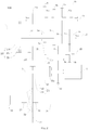
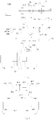
- a power transmission system according to embodiments of the present invention may be described below with reference to Figs. 1-12 .
- the power transmission system according to embodiments of the present invention may be used in vehicles such as hybrid vehicles as a power system, which may provide sufficient power and electric power for driving the vehicle.
- a power transmission system 100 may generally include a power unit and a transmission.
- the power unit may include an engine 4, a motor generator, and so on.
- the transmission unit may transmit power output from the power unit, thus driving or charging the vehicle.
- the power transmission system 100 may include at least an engine 4, a first motor generator 51, and a transmission unit.
- the transmission unit includes a plurality of input shafts (e.g. a first input shaft 11, a second input shaft 12), a plurality of output shafts (e.g. a first output shaft 21, a second output shaft 22), a motor power shaft 3, a plurality of gears provided on related shafts (such as the input shaft, the output shaft, and the motor power shaft), and a gear shift member such as a synchronizer.
- a plurality of input shafts e.g. a first input shaft 11, a second input shaft 12
- a plurality of output shafts e.g. a first output shaft 21, a second output shaft 22
- a motor power shaft 3 e.g. a plurality of gears provided on related shafts (such as the input shaft, the output shaft, and the motor power shaft)
- a gear shift member such as a synchronizer.
- the engine 4 is configured to selectively engage with at least one of the input shafts, when the engine 4 performs power transmission with the input shaft(s). For example, when the engine 4 is transmitting power to the input shaft, the engine 4 may selectively engage with one of the input shafts to transmit power. In some embodiments, the engine 4 may be selectively engage with two or more of the input shafts simultaneously to transmit power.
- the plurality of input shafts include a first input shaft 11 and a second input shaft 12.
- the engine 4 may selectively engage with one of the first and second input shafts 11, 12 to transmit power.
- the engine 4 may engage with the first and second input shafts 11, 12 simultaneously to transmit power. It should be noted that, in the present embodiment, the engine 4 may be disengaged from the first and second input shafts 11, 12 simultaneously.
- the power transmission between the input shaft(s) and the output shaft(s) is achieved by shaft gear pairs.
- each of the input shafts has a shaft driving gear provided there on
- each of the output shafts has a shaft driven gear provided thereon, so that a plurality of gear pairs with different velocity ratio are formed by meshes of corresponding shaft driving gears and shaft driven gears.
- the transmission unit may be a five-speed transmission, i.e. the transmission unit may include a first-gear gear pair, a second-gear gear pair, a third-gear gear pair, a fourth-gear gear pair and a fifth-gear gear pair.
- the transmission unit may not be limited to the five-speed transmission as disclosed in the present embodiment.
- the motor power shaft 3 is configured to rotate together with one of the input shafts, such as the second input shaft 12.
- the motor power shaft 3 rotates together with this input shaft while receiving the power.
- this input shaft rotates together with the motor power shaft 3 while receiving power.
- the input shaft(s) may rotate together with the motor power shaft 3 when the vehicle including the power transmission system 100 is operated in some specific conditions (will be discussed below with reference to detailed embodiments) in which power needs to be transmitted between the motor power shaft 3 and the input shaft(s).
- a gear rotates together with a shaft, i.e. when the gear rotates, the relative shaft rotates together; alternatively, when the shaft rotates, the relative gear rotates together.
- one shaft rotates together with the other one shaft, i.e. when the one shaft rotates, the other one shaft rotates together.
- one gear rotate together with the other one gear, i.e. when the one gear rotates, the other one gear rotates together.
- the first motor generator 51 may be configured to rotate together with the motor power shaft 3. For example, when functioning as a motor, the first motor generator 51 outputs the power to the motor power shaft 3. In some embodiments, when functioning as a generator, power form the motor power shaft 3 may be transmitted to the first motor generator 51, thereby driving the first motor generator 51 to generate electric power.
- a motor generator (such as the first motor generator 51) may be understood as an apparatus which can function as a motor and a generator, unless specified or limited otherwise.
- the motor power shaft 3 may rotate together with one of the input shafts. In some embodiments, when the motor power shaft 3 is rotating together with the one of the input shafts, the first motor generator 51 may use at least a part of power output by the engine 4 to generate electric power when the vehicle is parking or running.
- a part of power output by the engine 4 may be transmitted to the first motor generator 51 via the motor power shaft 3, such that the first motor generator 51 is driven to generate electric power, thus accomplishing a condition of charging and driving the vehicle at same time.
- a part of power output by the engine 4 may be transmitted to the first motor generator 51 via the motor power shaft 3, such that the first motor generator 51 is driven to generate electric power, thus accomplishing a condition of charging the vehicle while parking (such as charging the vehicle while the vehicle is not running).
- the motor power shaft 3 is configured to rotate together with one of the output shafts, such as the second output shaft 22.
- the motor power shaft 3 may rotate together with this output shaft to transmit power.
- the first motor generator 51 may generate power and transmit the power to the one output shaft, thereby driving the vehicle to run.
- the first motor generator 51 may output power as a motor to drive the vehicle to run.
- the motor power shaft 3 may be a motor shaft of the first motor generator 51. In some embodiments, the motor power shaft 3 may be a shaft different from the motor shaft of the first motor generator 51.
- the power transmission system 100 With the power transmission system 100 according to embodiments of the present invention, a number of charging modes of the vehicle are increased. For example, it is possible for charging the vehicle when the vehicle is running and parking. Therefore, deficiencies such like single charging mode and low charging efficiency of a conventional power transmission system may be solved at some extend, in other words, the charging modes of the vehicle are expanded.
- a motor synchronizer 33c disposed on the motor power shaft 3, a first motor gear 31 and a second motor gear 32 may be described in detail.
- the first motor gear 31 and the second motor gear 32 may both freely fitted over the motor power shaft 3.
- the motor power shaft 3 and the first motor gear 31 may rotate with different rotating speeds, and the motor power shaft 3 and the second motor gear 32 may rotate with different rotating speeds.
- the first motor gear 31 is configured to rotate together with one of the input shafts
- the second motor gear 32 is configured to rotate together with one of the output shafts.
- the first motor gear 31 is configured to rotate together with the second input shaft 12
- the second motor gear 32 is configured to rotate together with the second output shaft 22.
- the motor synchronizer 33c is disposed on the motor power shaft 3 and between the first motor gear 31 and the second motor gear 32.
- the motor synchronizer 33c includes an engaging sleeve which may move along an axial direction of the motor power shaft 3.
- the engaging sleeve of the motor synchronizer 33c may move leftward or rightward along the axial direction of the motor power shaft 3 under the drive of a shift fork mechanism of the vehicle.
- the motor synchronizer 33c is disposed between the first motor gear 31 and the second motor gear 32, thus the motor synchronizer 33c may selectively engage the motor power shaft 3 with one of the first motor gear 31 and the second motor gear 32.
- the engaging sleeve of the motor synchronizer 33c may move leftward to engage the first motor gear 31 with the motor power shaft 3, such that the motor power shaft 3 and the first motor gear 31 may rotate synchronously. In some embodiments, the engaging sleeve of the motor synchronizer 33c may move rightward to engage the second motor gear 32 with the motor power shaft 3, such that the motor power shaft 3 and the second motor gear 32 may rotate synchronously.
- the engaging sleeve of the motor synchronizer 33c may be positioned in a neutral position (such as an initial position). When the engaging sleeve of the motor synchronizer 33c is in the neutral position, the motor synchronizer 33c may be disengaged from the first motor gear 31 and be disengaged from the second motor gear 32.
- a gear ring is disposed on a side of the first motor gear 31 facing the motor synchronizer 33c, and a gear ring is disposed on a side of the second motor gear 32 facing the motor synchronizer 33c, thus facilitating the engagement between the first motor gear 31 and the motor synchronizer 33c and the engagement between the second motor gear 32 and the motor synchronizer 33c.
- the motor power shaft 3 may selectively rotate together with one of the input shafts or may selectively rotate together with one of the output shafts via synchronization of the motor synchronizer 33c, i.e., synchronizing the first motor gear 31 or the synchronizing the second motor gear 32.
- the motor synchronizer 33c may synchronize the first motor gear 31, i.e., the motor synchronizer 33c may engage the first motor gear 31 with the motor power shaft 3, and therefore the motor power shaft 3 may rotate together with one of the input shafts, such as the second input shaft 12.
- the motor synchronizer 33c may synchronize the second motor gear 32, i.e., the motor synchronizer 33c may engage the second motor gear 32 with the motor power shaft 3, and therefore the motor power shaft 3 may rotate together with one of the output shafts, such as the second output shaft 22.
- a reverse unit of the power transmission system 100 may be described below in detail.
- the first motor gear 31 may rotate together with one of the input shafts.
- the first motor gear 31 may perform a direct transmission or indirect transmission with the shift driving gear(s) disposed on the one input shaft, thus achieving the object of rotating together with the one input shaft.
- the first motor gear 31 may perform an indirect transmission with a corresponding shift driving gear (such as a second-gear driving gear 2a) via a middle idler 73.
- the middle idler 73 is configured to engage with the corresponding shift driving gear and the first motor gear 31.
- the reverse gear 71 is freely fitted over the motor power shaft 3, the reverse idler gear 72 is configured to mesh with the reverse gear 71 and configured to selectively rotate together with the middle idler 73.
- the reverse idler gear 72 is freely fitted over the second output shaft 22 and the reverse idler gear 72 and the middle idler 73 can rotate with different rotating speeds.
- the reverse idler gear 72 may engage with the middle idler 73 to rotate with the middle idler 73 synchronously when it is necessary.
- the middle idler 73 may rotate together with the reverse idler gear 72 via the synchronization of a reverse synchronizer 74c.
- the reverse synchronizer 74c is configured to synchronize the reverse idler gear 72 and the middle idler 73.
- the reverse idler gear 72 includes a gear sleeve 721.
- the gear sleeve 721 may be freely fitted over the second output shaft 22, and the middle idler 73 may be freely fitted over the gear sleeve 721.
- the reverse synchronizer 74c may be disposed on the gear sleeve 721 and configured to engage with the middle idler 73.
- the reverse idler gear 72 includes a gear sleeve 721 freely fitted over the second output shaft 22, and the middle idler 73 may be freely fitted over the gear sleeve 721.
- the reverse synchronizer 74c may be disposed on the middle idler 73 and configured to engage with the gear sleeve 721 or to engage with the reverse idler gear 72.
- both the reverse idler gear 72 and the middle idler 73 are freely fitted over one of the output shafts.
- both the reverse idler gear 72 and the middle idler 73 are freely fitted over the second output shaft 22.
- the reverse idler gear 72 may be adjacent to the middle idler 73, and the reverse synchronizer 74c may be disposed on the middle idler 73 and configured to engage with the reverse idler gear 72.
- the reverse synchronizer 74c may be disposed on the reverse idler gear 72 and configured to engage with the middle idler 73.
- the above reverse unit is applied, and therefore a mechanical reverse mode, an electric reverse mode and a hybrid (both mechanic and electric) reverse mode may be achieved.
- the reverse of the vehicle is accomplished with power from the engine 4.
- the engine 4 generates power and transmits the power to one of the input shafts, such as the second input shaft 12, to cause the input shaft to rotate together with the middle idler 73.
- the power is transmitted to the reverse gear 71 via synchronization by the reverse synchronizer 74c (synchronizing the middle idler 73 and the reverse idler gear 72), and then the reverse gear 71 transmits the power to wheels of the vehicle.
- the reverse synchronizer 74c may engage the middle idler 73 with the reverse idler gear 72.
- the reverse-driving of the vehicle may be achieved with power from the first motor generator.
- the first motor generator 51 may generate power and transmit the power to the reverse gear 71 via synchronization of the reverse synchronizer 74c (synchronizing the middle idler 73 and the reverse idler gear 72) and a synchronization of the motor synchronizer 33c (synchronizing the first motor gear 31), and then the reverse gear 71 transmits the power to the wheels of the vehicle, thus reversing the vehicle.
- the first motor generator 51 may be operated as a motor and generate power which is to be transmitted to the reverse gear 71 via the motor power shaft 3, the motor synchronizer 33c, the first motor gear 31, the middle idler 73, the reverse synchronizer 74c, and the reverse idler gear 72 sequentially.
- the middle idler 73 and the reverse idler gear 72 may be engaged via the reverse synchronizer 74c, and the motor power shaft 3 and the first motor gear 31 may be engaged via the motor synchronizer 33c.
- the reverse of the vehicle may be achieved with the engine 4 and the first motor generator 51.
- the hybrid reverse mode may be a combination of the above mechanical reverse mode and the electric reverse mode.
- the engine unit 4 may generate first power and transmit the first power to one of the input shafts, and then the first power may be transmitted to the reverse gear 71 via synchronization of the reverse synchronizer 74c.
- the first motor generator 51 may generate second power and transmit the second power the reverse gear 71 via the synchronization of the reverse synchronizer 74c and the synchronization of the motor synchronizer 33c (synchronizing the first motor gear 31).
- both the first power output by the engine 4 and the second power output by the first motor generator may be transmitted to the reverse gear 71 and output from the reverse gear 71.
- the middle idler 73 and the reverse idler gear 72 may be engaged by the reverse synchronizer 74c, and the motor power shaft 3 and the first motor gear 31 may be engaged by the motor synchronizer 33c.
- three reverse modes including the mechanical reverse mode, the electric reverse mode and the hybrid reverse mode may be achieved, thus increasing the reverse modes and facilitating a user to shift within the three reverse modes according to a practical condition, and therefore different driving requirements may be satisfied.
- the electric reverse mode When the vehicle has sufficient electric power, the electric reverse mode may be used. In the electric reverse mode, harmful exhaust gases can be minimized, and the energy consumption can be reduced. It is known to those skilled in the art that, an unskilled driver will take longer time and more maneuvers to park the vehicle at a predetermined position. Considering that the engine 4 may generate more harmful gases during a low-speed reverse process and that the engine 4 has relatively higher fuel consumption, because the engine is at an uneconomical rotating speed during the reverse process, the electric reverse mode of the present invention is highly effective in reducing fuel consumption during such a low-speed reverse process. In addition, with the generator being used as a power source, harmful exhaust gases can be minimized, and the energy consumption in a low-speed reverse process can also be decreased. Therefore, the fuel economy of the engine 4 may be enhanced.
- the mechanical reverse mode When the vehicle has insufficient or relatively less electric power, the mechanical reverse mode may be used. In a case that the vehicle needs to be reversed quickly or that the vehicle needs to be reversed with a larger power, the hybrid reverse mode may be used, thus enhancing the power of the vehicle and providing better driving experience to the user.
- the power transmission system 100 may have another electric reverse mode and another hybrid reverse mode, which will be discussed below with reference to detailed embodiments.
- the input shaft(s), the output shat(s), the shift driving gears and the shift driven gears of the power transmission system 100 will be described below with reference to embodiments shown in Figs. 1-12 .
- the plurality of input shafts include a first input shaft 11 and a second input shaft 12.
- the second input shaft 12 may be hollow and the first input shaft 11 may be solid.
- One part of the first input shaft 11 may be inserted within the hollow second input shaft 12, and the other part of the first input shaft 11 may extend out of the second input shaft 12 along an axial direction of the second input shaft 12.
- the first input shaft 11 and the second input shaft 12 may be arranged coaxially.
- the plurality of output shafts may include a first output shaft 21 and a second output shaft 22.
- the first output shaft 21 and the second output shaft 22 may be arranged coaxially with the input shafts (such as the first input shaft 11 and the second input shaft 12). Both the first output shaft 21 and the second output shaft 22 may be solid.
- the power transmission system 100 may have five gear transmission types. Specifically, odd number-gear shift driving gears may be arranged on the first input shaft 11, while even number-gear shift driving gear may be arranged on the second input shaft 12.
- the first input shaft 11 may transmit power from gear pairs of odd number-gear
- the second input shaft 12 may transmit power from gear pairs of even number-gear.
- a first-gear driving gear 1a, a third-gear driving gear 3a and a fifth-gear driving gear 5a may be arranged on the first input shaft 11, and a second-gear driving gear 2a and a fourth-gear driving gear 4a may be arranged on the second input shaft 12.
- Each of the first-gear to fifth-gear driving gears 1a, 2a, 3a, 4a, 5a may rotate synchronously with a corresponding input shaft.
- a first-gear driven gear 1b, a second-gear driven gear 2b, a third-gear driven gear 3b and a fourth-gear driven gear 4b may be disposed on the first output shaft 21, and a fifth-gear gear 5b may be disposed on the second output shaft 22.
- Each of the first-gear to fifth-gear driven gear 1b, 2b, 3b, 4b, 5b may be freely fitted over a corresponding output shaft.
- Each of the shift driven gears and the corresponding output shaft may rotate with different speeds.
- the first-gear driving gear 1a may mesh with the first-gear driven gear 1b to form one gear pair
- the second-gear driving gear 2a may mesh with the second-gear driven gear 2b to form one gear pair
- the third-gear driving gear 3a may mesh with the second-gear driven gear 3b to form one gear pair
- the fourth-gear driving gear 4a may mesh with the fourth-gear driven gear 4b to form one gear pair
- the fifth-gear driving gear 5a may mesh with the fifth-gear driven gear 5b to form one gear pair, thereby five pairs of gear pairs are formed.
- a synchronizer is provided to synchronize the shift driven gear and the corresponding output shaft, thus achieving the object of power transmission.
- the power transmission system 100 includes a first-third gear synchronizer 13c, a second-fourth gear synchronizer 24c and a fifth gear synchronizer 5c.
- the first-third gear synchronizer 13c is disposed on the first output shaft 21 and between the first-gear driven gear 1b and the third-gear driven gear 3b.
- the first-third gear synchronizer 13c may engage the first-gear driven gear 1b with the first output shaft 21 or engage the third-gear driven gear 3b with the first output shaft 21, such that the shift driven gear may rotate synchronously with the corresponding output shaft, e.g. the first-gear driven gear 1b and the first output shaft 21 may rotate synchronously, and the third-gear driven gear 3b and the first output shaft 21 may rotate synchronously.
- the first-third gear synchronizer 13c includes an engaging sleeve.
- the engaging sleeve of the first-third gear synchronizer 13c may move leftward to engage the third-gear driven gear 3b with the first output shaft 21, such that the third-gear driven gear 3b and the first output shaft 21 may rotate synchronously.
- the engaging sleeve of the first-third gear synchronizer 13c may move rightward to engage first-gear driven gear 1b with the first output shaft 21, such that the first-gear driven gear 1b and the first output shaft 21 may rotate synchronously.
- the second-fourth gear synchronizer 24c is disposed on the first output shaft 21 and between the second-gear driven gear 2b and the fourth-gear driven gear 4b.
- the second-fourth gear synchronizer 24c may engage the second-gear driven gear 2b with the first output shaft 21 or engage the fourth-gear driven gear 4b with the first output shaft 21, such that the shift driven gear may rotate synchronously with the corresponding output shaft.
- the second-gear driven gear 2b and the first output shaft 21 may rotate synchronously
- the fourth-gear driven gear 4b and the first output shaft 21 may rotate synchronously.
- the second-fourth gear synchronizer 24c includes an engaging sleeve.
- the engaging sleeve of the second-fourth gear synchronizer 24c may move leftward to engage the second-gear driven gear 2b with the first output shaft 21, such that the second-gear driven gear 2b and the first output shaft 21 may rotate synchronously.
- the engaging sleeve of the second-fourth gear synchronizer 24c may move rightward to engage fourth-gear driven gear 4b with the first output shaft 21, such that the fourth-gear driven gear 4b and the first output shaft 21 may rotate synchronously.
- the fifth gear synchronizer 5c is disposed on the second output shaft 22 and located on a side, such as left side, of the fifth-gear driven gear 5b.
- the fifth gear synchronizer 5c may engage the fifth-gear driven gear 5b with the second output shaft 22.
- the fifth gear synchronizer 5c includes an engaging sleeve, the engaging sleeve of the fifth gear synchronizer 5c may move rightward to engage the fifth-gear driven gear 5b with the second output shaft 22, such that the fifth-gear driven gear 5b and the second output shaft 22 may rotate synchronously.
- the reverse idler gear 72, the middle idler 73 are positioned on the second output shaft 22
- the fifth-gear driven gear 5b is positioned on the second output shaft 22 and configured to solely engage the fifth-gear driven gear 5b with the second output shaft 22
- the reverse synchronizer 74c is configured to merely engage the middle idler 73 and the reverse idler gear 72.
- the reverse synchronizer 74c and the fifth gear synchronizer 5c may share a shift fork mechanism. Therefore, one shift fork mechanism is sufficient for the present invention, instead of tow shift fork mechanisms, i.e. one shift fork mechanism is saved, thus the structure of the power transmission system 100 can be more compact.
- the shift fork mechanism may drive the engaging sleeve of the fifth gear synchronizer 5c and the engaging sleeve of the reverse synchronizer 74c.
- the fifth gear synchronizer 5c may engage the fifth-gear driven gear 5b with the second output shaft 22, but the reverse idler gear 72 and the middle idler 73 are not engaged by the fifth gear synchronizer 5c.
- the shift fork mechanism drives the engaging sleeve of the reverse synchronizer 74c to engage the reverse idler gear 72 with the middle idler 73
- the fifth-gear driven gear 5b and the second output shaft 22 are not engaged by the fifth gear synchronizer 5c.
- the engaging sleeve of the reverse synchronizer 74c and the engaging sleeve of the fifth gear synchronizer 5c are provided in the present embodiment for better understanding of the present invention, and therefore may not be construed as a limit to the present invention.
- the engine 4 may transmit power with the first input shaft 11 and the second input shaft 12 via a dual clutch 2d, or the engine 4 may disengage from the first input shaft 11 and the second input shaft 12 via a dual clutch 2d.
- the dual clutch 2d includes an input terminal 23d, a first output terminal 21d and a second output terminal 22d.
- the engine 4 is connected with the input terminal 23d of the dual clutch 2d.
- the engine 4 is connected with the input terminal 23d by at least one selected from a group consisting of a flywheel, a damper, a torsional disk, etc.
- the first output terminal 21d is connected with the first input shaft 11, such that the first output terminal 21d and the first input shaft 11 may rotate synchronously.
- the second output terminal 22d is connected with the second input shaft 12, such that the second output terminal 22d and the second input shaft 12 may rotate synchronously.
- the input terminal 23d may include a shell of the dual clutch 2d, and each of the first output terminal 21d and the second output terminal 22d may include one driven disk of the dual clutch 2d.
- the shell is disengaged from the driven disk, i.e. the input terminal 23d is disengaged from the first output terminal 21d and is disengaged from the second output terminal 22d.
- the shell is controlled to engage with a corresponding driven disk, thus the shell and this driven disk may rotate synchronously.
- the input terminal 23d may engage with one of the first output terminal 21d and the second output terminal 22d, thus transmitting power from the input terminal 23d to one of the first output terminal 21d and the second output terminal 22d to output the power.
- the shell may engage with two driven disks simultaneously.
- the input terminal 23d is engaged with both the first output terminal 21d and the second output terminal 22d, and thereby power from the input terminal 23d may be transmitted to the first output terminal 21d and the second output terminal 22d to be output.
- the engaging state of the dual clutch 2d may be controlled according to practical condition, and may be adjusted accordingly based on a current transmission mode.
- the input terminal 23d may be disengaged from the two output terminals, for example, the first output terminal 21d and the second output terminal 22d.
- the input terminal 23d may engage with at least one of the two output terminals, for example, the first output terminal 21d and the second output terminal 22d.
- the second motor gear 32 may rotate together with one of the output shafts.
- a transmission gear 6 is fixed on the second output shaft 22 and configured to directly mesh with the second motor gear 32.
- the power transmission system 100 may have another electric reverse mode and another hybrid reverse mode.
- the second motor gear 32 may mesh with the transmission gear 6 fixed on the second output shaft 22 to form a power transmission passage, and thereby power from the first motor generator 51 may be transmitted via this power transmission passage. In this way, another reverse mode may be achieved.
- the first motor generator 51 may output power and transmit the power to the second output shaft 22 via the synchronization of the motor synchronizer 33c (for example, synchronizing the second motor gear 32), and then the second output shaft 22 output the power to wheels of the vehicle, thus reversing the vehicle.
- the motor synchronizer 33c for example, synchronizing the second motor gear 32
- the first motor generator 51 is operated as a motor and generates power which is transmitted to the wheels of the vehicle via the motor power shaft 3, the motor synchronizer, the second motor gear 32, the transmission gear, and the second output shaft 22 sequentially.
- the motor synchronizer 33c may engage the motor power shaft 3 with the second motor gear 32, while the reverse synchronizer 74c does not engage the middle idler 73 and the reverse idler gear 72, and power for reversing the vehicle may not be output from the reverse gear 71.
- the engine 4 may generate first power and transmit the first power to one of the input shafts, and then the power is transmitted to the reverse gear 71 via synchronization of the reverse synchronizer 74c.
- the first motor generator 51 may generate second power and transmit the second power to the second output shaft 22 via synchronization of the motor synchronizer 33c (synchronizing the second motor gear 32 and the second output shaft 22), and then the second output shaft 22 may transmit the second power to the wheels to reverse the vehicle.
- the vehicle is reversed by powers from both the engine 4 and the first motor generator 51, i.e. the first power and the second power.
- the first power and the second power may be coupled before output to the wheels.
- the first power and the second power may be coupled at a shift driven gear 74 of a main reducer of the vehicle, and the coupled power may be transmitted to the wheels to reverse the vehicle.
- the reverse synchronizer 74c engages the middle idler 73 and the reverse idler gear 72
- the motor synchronizer 33c engages the motor power shaft 3 with the second motor gear 32
- a part of power for reversing the vehicle may be output from the reverse gear 71
- the other part of power for reversing the vehicle may be output from the second output shaft 22.
- power for reversing the vehicle may be from the first motor generator 51, which is similar as that in the aforementioned electric reverse mode.
- power generated by the first motor generator 51 is transmitted to the reverse gear 71 and then to wheels of the vehicle to reverse the vehicle
- power generated by the first motor generator 51 is output to the wheels via the second output shaft 22.
- power for reversing the vehicle does not pass the reverse gear 71.
- the transmission passage of power from the engine 4 and the transmission passage of power from the first motor generator 51 are combined, which is similar to that in the aforementioned hybrid reverse mode.
- the differences between the another hybrid reverse mode and the aforementioned hybrid reverse mode are similar to those between the another electric reverse mode and the aforementioned electric reverse mode described above, thus details thereof are omitted herein.
- a number of the reverse modes of the vehicle are increased, which may provide a driver more options to reverse the vehicle. In this way, the driver may be provided more driving fun and reverse of the vehicle in different road conditions may be satisfied.
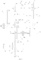
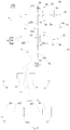
- the power transmission system 100 includes three power output shafts, i.e. a first output shaft 21, a second output shaft 22, and a motor power shaft 3. These power output shafts, a differential 75, and relationships therebetween may be described below in detail with reference to Figs. 2-12 .
- the differential 75 may be disposed between a pair of front wheels of the vehicle. In some embodiments, the differential 75 may be disposed between a pair of rear wheels of the vehicle. The differential 75 may allow the left and right driving wheels to roll with different angular speeds when the vehicle is turning or running on a rough road, , and therefore the left and right driving wheels of the vehicle may perform pure rolling motions on the ground.
- a shift driven gear 74 of a main reducer may be disposed on the differential 75, for example, the shift driven gear 74 may be disposed on a shell of the differential 75. In some embodiments, the shift driven gear 74 may be a bevel gear, without particular limits in the present invention.
- a first shift driven gear 211 is fixed on the first output shaft 21 and configured to rotate with the first output shaft 21 synchronously.
- the first shift driven gear 211 may mesh with the shift driven gear 74, thus transmitting power transmitted to the first output shaft 21 from the first output gear 211 to the shift driven gear 74 and the differential 75.
- a second shift driven gear 221 is fixed on the second output shaft 22 and configured to rotate with the second output shaft 22 synchronously.
- the second shift driven gear 221 may mesh with the shift driven gear 74, thus transmitting power transmitted to the second output shaft 22 from the second output gear 221 to the shift driven gear 74 and the differential 75.
- the reverse gear 71 is used as the power output terminal in most reverse modes and is configured to mesh with the shift driven gear 74.
- the reverse gear 71 may be a duplex gear, and therefore proper reverse speed ratio may be obtained.
- the reverse gear 71 is a duplex gear, a part of the reverse gear 71 may mesh with the reverse idler gear 72, and another part of the reverse gear 71 may mesh with the shift driven gear 74.
- the reverse gear 71 includes a first gear part 711 to mesh with the shift driven gear 74 and a second gear part 712 to mesh with the reverse idler gear 72.
- the power transmission system 100 may be used in various different conditions, such as a parking-charging condition (for example, charging the vehicle while the vehicle is parking), a running-charging condition (for example, charging the vehicle while the vehicle is running and both clutch parts of the dual clutch 2d are engaged), a speed adjusting condition.
- a parking-charging condition for example, charging the vehicle while the vehicle is parking
- a running-charging condition for example, charging the vehicle while the vehicle is running and both clutch parts of the dual clutch 2d are engaged
- a speed adjusting condition for example, a speed adjusting condition.
- the engine 4 is configured to generate power and output the power to one of the input shafts, for example, an input shaft rotating together with the first motor gear 31, such as the second input shaft 12, and the motor synchronizer 33c synchronizes the first motor gear 31 and the input shaft such as the second input shaft 12 to transmit the power to the first motor generator 51, thereby driving the first motor generator 51 to generate electric power.
- the input shafts for example, an input shaft rotating together with the first motor gear 31, such as the second input shaft 12, and the motor synchronizer 33c synchronizes the first motor gear 31 and the input shaft such as the second input shaft 12 to transmit the power to the first motor generator 51, thereby driving the first motor generator 51 to generate electric power.
- the engine 4 in the parking-charging state, the engine 4 generates power and transmits the power to the second input shaft 12 via the dual clutch 2d.
- the motor synchronizer 33c may engage the motor power shaft 3 and the first motor gear 31, and therefore the power generated by the engine 4 may be transmitted to the motor power shaft 3 via the second input shaft 12, the middle idler 73, the first motor gear 31, and the motor synchronizer 33c sequentially.
- the motor power shaft 3 may transmit the power to the first motor generator 51, and the first motor generator 51 may be driven to generate electric power as a generator.
- charging the vehicle when the vehicle is parking may be achieved, and the number of the charging modes is increased.
- the parking-charging mode the vehicle is not running, all power from the engine 4 may be used to charge the vehicle, thus providing a fast charging performance and enhancing the charging efficiency.
- the input terminal 23d is engaged with the first output terminal 21d and engaged with the second output terminal 22d simultaneously, a part of power generated by the engine 4 may be output to one of the output shafts to drive the wheels of the vehicle, and the other part of power may be transmitted to the first motor generator 51 via the motor power shaft 3, thus driving the first motor generator 51 to generate electric power.
- a part of power generated by the engine 4 may be output from the first output shaft 21 or the second output shaft 22, such as via the first-gear gear pair, the third-gear gear pair or the fifth-gear gear pair.
- the other part of power generated by the engine 4 may be transmitted to the first motor generator 51 via the first motor gear 31, the motor synchronizer 33c, the motor power shaft 3 sequentially, thus driving the first motor generator 51 to generate electric power.
- a conventional dual clutch generally have two gear parts, and only one gear part is used when the dual clutch is working.
- two gears parts of the dual clutch 2d may be both engaged (for example, the input terminal 23d is engaged with the first output terminal 21d and engaged with the second output terminal 22d simultaneously) when the dual clutch 2d is working.
- a part of power from the engine 4 may be output to wheels of the vehicle via one output shaft to drive the vehicle to run, and the other part of power from the engine 4 may be transmitted to the first motor generator 51 to drive the first motor generator 51 to generate electric power. In this way, transmission modes of the vehicle are increased, and charging the vehicle while the vehicle is running may be achieved.
- the motor synchronizer 33c is disposed between the first motor gear 31 and the second motor gear 32, and therefore power generated by the first motor generator 51 may be selectively output via the first motor gear 31 or the second motor gear 32.
- the vehicle switches from outputting power via the first motor gear 31 to outputting power via the second motor gear 32 by the synchronization of the motor synchronizer 33c.
- the engaging sleeve of the synchronizer can move from an engaging position at the first motor gear to an engaging position at the second motor gear.
- a speed ratio of a transmission passage from the first motor gear 31 to the shift driven gear 74 can be different from that of a transmission passage from the second motor gear 32 to the shift driven gear 74, the second motor gear 32 and the motor power shaft 3 may rotate at different rotating speeds during the switching process. In this way, the synchronization time and wear of the synchronizer may be increased, and therefore the transmission efficiency may be reduced. Further, an unsmooth traveling of the vehicle caused by power interruption or power stop may occur because the synchronization cannot be completed during a long term.
- the first motor generator 51 is controlled to adjust the rotating speed of the motor power shaft 3 based on the rotating speed of the second motor gear 32.
- the rotating speed of the motor power shaft 3 may be increased or decreased with the rotating speed of the second motor gear 32 as a target speed, and therefore the rotating speed of the motor power shaft 3 may be matched with the rotating speed of the second motor gear 32 during a shorter time, for example, the rotating speed of the motor power shaft 3 is equal to or substantially equal to the rotating speed of the second motor gear 32.
- the motor synchronizer 33c may engage the second motor gear 32 with the motor power shaft 3 rapidly, and therefore the synchronization time of the motor synchronizer 33c may be reduced and the transmission efficiency, the synchronization controllability and the synchronization real-time capability may be improved. In addition, the life of the motor synchronizer 33c may be prolonged and the maintenance cost of the vehicle may be reduced.
- the first motor generator 51 may adjust the rotating speed of the motor power shaft 3 based on the rotating speed of the first motor gear 31.
- the first motor generator 51 may increase or decrease the rotating speed of the motor power shaft 3 with the rotating speed of the first motor gear 31 as a target speed, such that the rotating speed of the motor power shaft 3 may be matched with the rotating speed of the first motor gear 31 in a shortest time, thus enhancing the engaging efficiency of the motor synchronizer 33c.
- the first motor generator 51 may adjust the rotating speed of the motor power shaft 3 with the rotating speed of the other one of the first motor gear 31 and the second motor gear 32 as a target speed.
- the vehicle may run in an electric mode, i.e. the vehicle is driven by the first motor generator 51.
- the present invention is not limited to this embodiment.
- the motor synchronizer 33c may be switched from engaging with one of the first motor gear 31 and the second motor gear 32 to engaging with the other one of the first motor gear 31 and the second motor gear 32, the rotating speed of the motor power shaft 3 may be adjusted by the first motor generator 51.
- the first motor generator 51 may adjust the rotating speed of the motor power shaft 3, such that the rotating speed of the motor power shaft 3 may be matched with the rotating speed of the gear to be engaged, for example, the first motor gear 31 or the second motor gear 32.
- the first motor generator 51 may adjust the rotating speed of the motor power shaft 3 with the rotating speed of the gear to be engaged as a target speed, such that the rotating speed of the motor power shaft 3 may be matched with the rotating speed of the gear to be engaged in a shortest time, thus facilitating the engagement of the motor synchronizer 33c, significantly improving the transmission efficiency and reducing the transmission loss.
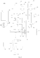
- the power transmission system 100 further includes a second motor generator 52. With the second motor generator 52, the power of the power transmission system 100 may be improved and transmission modes may be increased.
- the second motor generator 52 may perform power transmission with the shift driven gear 74 of the main reducer.
- a gear may be disposed on a motor shaft of the second motor generator 52, and the gear is configured to directly mesh with the shift driven gear 74 to perform power transmission.
- the second motor generator 52 is configured to connect with the first input shaft 11 or the first output shaft 21.
- the second motor generator 52 may be integral with the differential 75.
- the engine 4 and the first motor generator 51 are configured to drive front wheels of the vehicle, and the second motor generator 52 may be a wheel-side motor and configured to drive rear wheels.
- the second motor generator 52 may drive the pair of rear wheels via a reducing mechanism.
- two second motor generators 52 are provided, and each second motor generator 52 is configured to driven one rear wheel via a reducing mechanism.
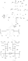
- the power transmission system 100 may include an electric differential lock unit.
- the electric differential lock unit may lock a pair of driving wheels when the vehicle is skidding, thus enhancing the antiskid performance and the trafficability performance of the vehicle.
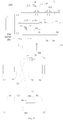
- the electric differential lock unit may include a third motor generator 201, a fourth motor generator 301 and an antiskid synchronizer 503.
- the engine 4 and/or the first motor generator 51 is configured to drive a first pair of wheels 76
- the third motor generator 201 and the fourth motor generator 301 are configured to driven a second pair of wheels 77
- the first pair of wheels 76 are one pair of the pair of front wheels and the pair of the rear wheels
- the second pair of wheels 77 are the other one pair of the pair of front wheels and the pair of the rear wheels.
- the engine and the first motor generator 51 may drive the pair of front wheels
- the third motor generator 201 and the fourth motor generator 301 may drive the pair of rear wheels.
- the third motor generator 201 is configured to rotate together with one of the second pair of wheels 77.
- the third motor generator 201 may output power to this one wheel to drive this one wheel to rotate.
- power from this one wheel may be transmitted to the third motor generator 201, thus driving the third motor generator 201 to generate electric power.
- the fourth motor generator 301 is configured to rotate together with the other one of the second pair of wheels 77.
- the fourth motor generator 301 may output power to the other one wheel to drive the other wheel to rotate.
- power form the other wheel may be transmitted to the fourth motor generator 301, thus driving the fourth motor generator 301 to generate electric power.
- the third motor generator 201 is configured to rotate together with a left rear wheel of the vehicle
- the fourth motor generator 301 is configured to rotate together with a right rear wheel of the vehicle. This embodiment is provided for example, and the present invention should not be construed to be limited by this embodiment.
- the antiskid synchronizer 503 is configured to selectively synchronize the second pair of wheels 77, such that the second pair of wheels 77 may rotate synchronously.
- the antiskid synchronizer 503 may synchronize the second pair of wheels 77, i.e. the antiskid synchronizer 503 is in an engaged state, such that the second pair of wheels 77 may form a fixed engagement. In this way, the second pair of wheels 77 may rotate synchronously, without rotating at different rotating speeds.
- the third motor generator 201 and the fourth motor generator 301 may drive corresponding wheels respectively, such that the corresponding wheels may rotate at different rotating speeds, thus the object that different wheels rotates at different speeds may be achieved.
- the third motor generator 201 and the fourth motor generator 301 may drive the second pair of wheels 77 to rotate at a same rotating speed.
- the third motor generator 201 and the fourth motor generator 301 are provided and configured to drive the second pair of wheels 77 respectively, and therefore having the second pair of wheels 77 rotating at different rotating speeds may be achieved.
- the antiskid synchronizer 503 may synchronize the second pair of wheels 77 such that the second pair of wheels 77 rotate synchronously.
- powers output by two motors for example, the third motor generator 201 and the fourth motor generator 301) or one motor (for example, one of the third motor generator 201 and the fourth motor generator 301) may be coupled to drive the second pair of wheels 77 together, thus enhancing the antiskid capability and trafficability performance of the vehicle.
- the power transmission system 100 includes the antiskid synchronizer 503, and therefore a mechanical self-locking differential mechanism commonly used in an axle (such as a rear axle) a conventional power transmission system may be avoided.
- a mechanical self-locking differential mechanism commonly used in an axle (such as a rear axle) a conventional power transmission system may be avoided.
- the functions of a mechanical self-locking differential mechanism are performed by the antiskid synchronizer 503, and therefore the power transmission system 100 according to embodiments of the present invention may have a more compact structure and relatively lower cost.
- the third motor generator 201, the fourth motor generator 301, and transmission method thereof will be described below in detail with references to Figs. 5-12 .
- the third motor generator 201 may perform power transmission with the corresponding wheel via a gear mechanism.
- the fourth motor generator 301 may perform power transmission with the corresponding wheel via a gear mechanism.
- the gear mechanism has simple structure and is convenient for use in power transmission.
- a desired transmission ration may be obtained and the power transmission may be reliable.
- the third motor generator 201 and the fourth motor generator 301 may perform power transmission with corresponding wheel(s) via a same gear mechanism.
- the gear mechanism is common, and the power transmission system 100 may be highly symmetric, thus avoiding the center of gravity moving to one side. With one common gear mechanism, the center of gravity may be located right in the middle or substantially the middle of the two wheels, and both the stability and reliability of the power transmission system 100 may be improved.
- the gear mechanism between the third motor generator 201 and the corresponding wheel may include a first gear 401, a second gear 402, a third gear 403, and a fourth gear 404.
- the first gear 401 may be disposed on the first power output shaft 202 corresponding to the third motor generator 201, and the first gear 401 is configured to rotate synchronously with the first power output shaft 202.
- the first power output shaft 202 may output power generated by the third motor generator 201.
- the first power output shaft 202 may transmit power generated by the corresponding wheel to the third motor generator 201.
- the first power output shaft 202 and the third motor generator 201 may share a same motor shaft.
- the motor shaft of the first power output shaft 202 and the motor shaft the third motor generator 201 may be two individual parts different from each other. In the present embodiment, the motor shaft of the first power output shaft 202 and the motor shaft the third motor generator 201 may be connected to each other.
- a first drive shaft 204 is connected with a wheel corresponding to the third motor generator 201, and the second gear 402 is disposed on the first drive shaft 204 and configured to rotate synchronously with the first drive shaft 204.
- the third gear 403 and the first gear 401 are configured to mesh with each other, and the fourth gear 404 and the second gear 402 are configured to mesh with each other.
- the third gear 403 and the fourth gear 404 are coaxially arranged and may rotate synchronously.
- the gear mechanism between the fourth motor generator 301 and the corresponding wheel may include a fifth gear 405, a sixth gear 406, a seventh gear 407, and an eighth gear 408.
- the fifth gear 405 may be disposed on the second power output shaft 302 corresponding to the fourth motor generator 301, and the fifth gear 405 is configured to rotate synchronously with the second power output shaft 302.
- the second power output shaft 302 may output power generated by the fourth motor generator 301.
- the second power output shaft 302 may transmit power generated by the corresponding wheel to the fourth motor generator 301.
- the second power output shaft 302 and the fourth motor generator 301 may share a same motor shaft.
- the motor shaft of the second power output shaft 302 and the motor shaft the fourth motor generator 301 may be two individual parts different from each other.
- the motor shaft of the second power output shaft 302 and the motor shaft the fourth motor generator 301 may be connected to each other.
- a second drive shaft 304 is connected with a wheel corresponding to the fourth motor generator 301, and the sixth gear 406 is disposed on the second drive shaft 304 and configured to rotate synchronously with the second drive shaft 304.
- the seventh gear 407 and the fifth gear 405 are configured to mesh with each other, and the eighth gear 408 and the sixth gear 406 are configured to mesh with each other.
- the seventh gear 407 and the eighth gear 408 are coaxially arranged and may rotate synchronously.
- the first gear 401 and the fifth gear 405 may have a same structure, such as having a same size and a same teeth number.
- the second gear 402 and the sixth gear 406 may have the same structure, such as having a same size and a same teeth number.
- the third gear 403 and the seventh gear 407 may have the same structure, such as having a same size and a same teeth number.
- the fourth gear 404 and the eighth gear 408 may have the same structure, such as having a same size and a same teeth number. Therefore, versatility of the gear mechanism may be improved.
- the third gear 403 and the fourth gear 404 may be fixed on the first gear shaft 501, and the seventh gear 407 and the eighth gear 408 may be fixed on the second gear shaft 502.
- the third gear 403 and the fourth gear 404 may form a substantial ladder shape or a joint gear structure.
- the seventh gear 407 and the eighth gear 408 may form a substantial ladder shape or a joint gear structure.
- the antiskid synchronizer 503 may be disposed on the first drive shaft 204 and configured to selectively engage with the sixth gear 406.
- a gear ring may be provided on a side of the sixth gear 406 facing the antiskid synchronizer 503, and the antiskid synchronizer 503 may include an engaging sleeve to adapt to the gear ring. With the engagement of the antiskid synchronizer 503, the second pair of wheels 77 may rotate synchronously.
- the antiskid synchronizer 503 may be disposed on the first power output shaft 202 and configured to selectively engage with the fifth gear 405.
- a gear ring may be provided on a side of the fifth gear 405 facing the antiskid synchronizer 503, and the antiskid synchronizer 503 may include an engaging sleeve to adapt to the gear ring. With the engagement of the antiskid synchronizer 503, the second pair of wheels 77 may rotate synchronously.
- the antiskid synchronizer 503 may be disposed on the first gear shaft 501 and configured to selectively engage with the seventh gear 407.
- a gear ring may be provided on a side of the seventh gear 407 facing the antiskid synchronizer 503, and the antiskid synchronizer 503 may include an engaging sleeve to adapt to the gear ring. With the engagement of the antiskid synchronizer 503, the second pair of wheels 77 may rotate synchronously.
- the third motor generator 201 may be connected coaxially with a corresponding wheel
- the fourth motor generator 301 may be connected coaxially with a corresponding wheel.
- both the third motor generator 201 and the fourth motor generator 301 may be wheel-side motors, thus shortening the transmission passage, reducing the power transmission loss and enhancing the transmission efficiency.
- the antiskid synchronizer 503 may be disposed on the first power output shaft 202 corresponding to the third motor generator 201, and configured to selectively engage with the second power output shaft 302 corresponding to the fourth motor generator 301. With the engagement of the antiskid synchronizer 503, the second pair of wheels 77 may rotate synchronously.
- the power transmission system 100 and the conditions of the power transmission system 100 will be described below with reference to Figs. 2-12 .
- the engine 4 is connected with the input terminal 23d of the dual clutch 2d
- the first output terminal 21d of the dual clutch 2d is connected with the first input shaft 11
- the second output terminal 22d of the dual clutch 2d is connected with the second input shaft 12.
- the input terminal 23d may be disengaged from both the first output terminal 21d and the second output terminal 22d, or the input terminal 23d may engage with one of the first output terminal 21d and the second output terminal 22d, or the input terminal 23d may engage with both the first output terminal 21d and the second output terminal 22d.
- the second input shaft 12 may be a hollow shaft, and the first input shaft 11 may be a solid shaft.
- the second input shaft 12 is coaxially fitted over the first input shaft 11, and a part of the first input shaft 11 extends outside of the second input shaft 12 along an axial direction of the second input shaft 12.
- the first-gear driving gear 1a, the third-gear driving gear 3a and the fifth-gear driving gear 5a are disposed on the first input shaft 11 and configured to rotate synchronously with the first input shaft 11.
- the first-gear driving gear 1a is positioned on the right side of the fifth-gear driving gear 5a
- the third-gear driving gear 3a is positioned on the left side of the fifth-gear driving gear 5a.
- the second-gear driving gear 2a and the fourth-gear driving gear 4a are disposed on the second input shaft 12 and configured to rotate synchronously with the second input shaft 12, and the second-gear driving gear 2a is positioned on the left side and the fourth-gear driving gear 4a is positioned on the right side.
- the first output shaft 21 is arranged parallel to the two input shafts, i.e. the first and second input shafts 11, 12.
- the first-gear driven gear 1b, the second-gear driven gear 2b, the third-gear driven gear 3b and the fourth-gear driven gear 4b are freely fitted over the first output shaft 21.
- the first-gear driven gear 1b is configured to mesh directly with the first-gear driving gear 1a
- the second-gear driving gear 2a is configured to mesh directly with the second-gear driven gear 2b
- the third-gear driving gear 3a is configured to mesh directly with the third-gear driven gear 3b
- the fourth-gear driving gear 4a is configured to mesh directly with the fourth-gear driven gear 4b.
- the first-third gear synchronizer 13c, the second-fourth gear synchronizer 24c are disposed on the first output shaft 21, and the first-third gear synchronizer 13c is positioned between the first-gear driven gear 1b and the third-gear driven gear 3b and configured to selectively synchronize the first-gear driven gear 1b with the first output shaft 21 and to selectively synchronize the third-gear driven gear 3b and the first output shaft 21.
- the second-fourth gear synchronizer 24c is positioned between the second-gear driven gear 2b and the fourth-gear driven gear 4b and configured to selectively synchronize the second-gear driven gear 2b and the first output shaft 21 or to selectively synchronize the fourth-gear driven gear 4b and the first output shaft 21.
- the second output shaft 22 is arranged parallel to the two input shafts, i.e. the first and second input shafts 11, 12.
- the fifth-gear driven gear 5b is freely fitted over the second output shaft 22 and configured to directly mesh with the fifth-gear driving gear 5a.
- the fifth-gear synchronizer 5c is disposed on the second output shaft 22 and configured to synchronize the fifth-gear driven gear 5b and the second output shaft 22.
- the motor power shaft 3 is disposed coaxially with the two input shafts such as the first and second input shafts 11, 12 and the two output shafts such as the first and second output shafts 21, 22.
- the first motor gear 31 and the second motor gear 32 are freely fitted over the motor power shaft 3, and the first motor gear 31 is on the left while the second motor gear 32 is on the right.
- the motor synchronizer 33c is disposed on the motor power shaft 3 and positioned between the first motor gear 31 and the second motor gear 32.
- the motor synchronizer 33c is configured to selectively synchronize the first motor gear 31 and the motor power shaft 3 or to selectively synchronize the second motor gear 32 and the motor power shaft 3.
- the transmission gear 6 is disposed on the second output shaft 22 and configured to rotate synchronously with the second output shaft 22, and the reverse idler gear 72 is freely fitted over the second output shaft 22.
- the transmission gear 6 is configured to directly mesh with the second output shaft 22.
- the reverse idler gear 72 includes a gear sleeve 721 at one side thereof, and the gear sleeve 721 is freely fitted over the second output shaft 22.
- the middle idler 73 is freely fitted over the gear sleeve 721 and configured to mesh with the second-gear driving gear 2a and the first motor gear 31 respectively.
- the reverse synchronizer 74c is arranged on the gear sleeve 721 and configured to engage with the middle idler 73.
- the reverse gear 71 is configured as a duplex gear and includes a first gear part 712 configured to mesh with the reverse idler gear 72 and a second gear part 713 configured to directly mesh with the shift driven gear 74.
- the first output gear 211 is fixed on the first output shaft 21 and configured to mesh with the shift driven gear 74.
- the second output gear 221 is fixed on the second output shaft 22 and configured to mesh with the shift driven gear 74.
- the first motor generator 51 and the motor power shaft 3 are coaxially connected.
- the input terminal 23d of the dual clutch 2d is engaged with the second output terminal 22d while disengaged from the first output terminal 21d.
- the motor synchronizer 33c engages the first motor gear 31, such that power output by the engine 4 may be transmitted to the first motor generator 51 via the input terminal 23d, the second output terminal 22d, the second input shaft 12, the second-gear driving gear 2a, the middle idler 73, the first motor gear 31, the motor synchronizer 33c and the motor power shaft 3 sequentially, thus driving the first motor generator 51 to generate electric power.
- the speed ratio relates to parameters such as the rotating speed of the engine 4 in the parking state, the type of the first motor generator 51, and maximum rotating speed acceptable by the peripheral parts such as bearings, and so on.
- the speed ratio may be designed according to the above parameters and the power transmission ratio may be flexibly designed, thus making maximum use of the power from the engine 4 and achieving the object of quick charging.
- power from the engine 4 may be transmitted via a passage consisting of the second input shaft 12, the middle idler 73, the first motor gear 31 and the motor power shaft 3, and therefore the object of charging with an optimal fixed speed ratio may be achieved, and both the charging efficiency and the fuel economy of the engine are improved.
- the first motor generator 51 functions as a generator and can rotate along a predetermined rotating direction, such as the clockwise direction.
- the motor synchronizer 33c engages the first motor gear 31, and power output by the first motor generator 51 is transmitted to the second input shaft 12 via the first motor gear 31 and the middle idler 73. Then the second-fourth gear synchronizer 24c engages the second-gear driven gear 2b or the fourth-gear driven gear 4b, and therefore the power from the first motor generator 51 is output via the second-gear gear pair or the fourth-gear gear pair.
- the motor synchronizer 33c engages the second motor gear 32, and power output by the first motor generator 51 is transmitted to the second output shaft 22 via the second motor gear 32 and the transmission gear 6, and then output from the second output shaft 22.
- power from the first motor generator 51 may be transmitted to wheels of the vehicle via two power transmission passages having different speed ratios, thus driving the vehicle to run.
- different speed ratios may be selected accordingly to improve the operation efficiency of the first motor generator 51.
- the first motor generator 51 may adjust the rotating speed of the motor power shaft 3.
- the motor synchronizer 33c moves from an engaging position at the first motor gear 31 to an engaging position at the second motor gear 32.
- the first motor generator 51 may adjust the rotating speed of the motor power shaft 3 with the rotating speed of the second motor gear 32 as a target speed. In this way, the rotating speed of the motor power shaft 3 is matched with the rotating speed of the second motor gear 32, and thereby the motor synchronizer 33c may engage with the second motor gear 32 rapidly.
- the synchronization efficiency can be improved.
- the motor synchronizer 33c moves from an engaging position at the second motor gear 32 to an engaging position at the first motor gear 31.
- the first motor generator 51 may adjust the rotating speed of the motor power shaft 3 with the rotating speed of the first motor gear 31 as a target speed. In this way, the rotating speed of the motor power shaft 3 is matched with the rotating speed of the first motor gear 31, and thereby the motor synchronizer 33c may engage with the first motor gear 31 rapidly. Thus the synchronization efficiency is improved.
- the speed adjusting mode described above may be used in other conditions, such as in a hybrid condition, provided change of the engaging state of the motor synchronizer 33c is related.
- the above speed adjusting mode may be used in a condition in which the motor synchronizer 33c changes from engaging with the first motor gear 31 to engaging with the second motor gear 32.
- the above speed adjusting mode may be used in a condition in which the motor synchronizer 33c changes from engaging with the second motor gear 32 to engaging with the first motor gear 31.
- the first motor generator 51 When the power transmission system 100 is operated in the pure electric condition, the first motor generator 51 functions as a motor and can rotate along a predetermined rotating direction, such as the clockwise direction.
- the first-third gear synchronizer 13c is engaged with the first-gear driven gear 1b
- the input terminal 23d of the dual clutch 2d is engaged with the first output terminal 21d and disengaged from the second output terminal 22d
- the motor synchronizer 33c is engaged with the second motor gear 32.
- First power output by the engine 4 is transmitted to the first output shaft 21 via the first input shaft 11 and the first-gear gear pair
- second power output by the first motor generator 51 is transmitted to the second output shaft 22 via the second motor gear 32 and the transmission gear 6.
- the first power and the second power are coupled at the driven gar 74, and then distributed to wheels by the differential 75.
- the first motor generator 51 may adjust the speed, such that the shift driven gear 74 may synchronously receive the first power from the engine 4 and the second power from the first motor generator 51, thus ensuring a smooth power transmission.
- the second-fourth gear synchronizer 24c is engaged with the second-gear driven gear 2b
- the input terminal 23d of the dual clutch 2d is engaged with the second output terminal 22d and disengaged from the first output terminal 21d
- the motor synchronizer 33c is engaged with the second motor gear 32.
- First power output by the engine 4 is transmitted to the first output shaft 21 via the second input shaft 12 and the second-gear gear pair
- second power output by the first motor generator 51 is transmitted to the second output shaft 22 via the second motor gear 32 and the transmission gear 6.
- the first power and the second power are coupled at the driven gar 74, and then distributed to wheels by the differential 75.
- the first motor generator 51 may adjust the speed, such that the shift driven gear 74 may synchronously receive the first power from the engine 4 and the second power from the first motor generator 51, thus ensuring a smooth power transmission.
- the power transmission system 100 operates substantially the same as that in the first first-gear hybrid condition, with the exception that the first-third gear synchronizer 13c is engaged with the third-gear driven gear 3b and first power output by the engine 4 is output via the third-gear gear pair.
- the power transmission system 100 operates substantially the same as that in the first second-gear hybrid condition, with the exception that the second-fourth gear synchronizer 24c is engaged with the fourth-gear driven gear 4b and first power output by the engine 4 is output via the fourth-gear gear pair.
- the fifth gear synchronizer 5c is engaged with the first-gear driven gear 1b
- the input terminal 23d of the dual clutch 2d is engaged with the first output terminal 21d and disengaged from the second output terminal 22d
- the motor synchronizer 33c is engaged with the second motor gear 32.
- First power output by the engine 4 is transmitted to the second output shaft 22 via the first input shaft 11 and the fifth-gear gear pair
- second power output by the first motor generator 51 is transmitted to the second output shaft 22 via the second motor gear 32 and the transmission gear 6.
- the first power and the second power are coupled at the driven gar 74, and then distributed to wheels by the differential 75.
- the first motor generator 51 may adjust the speed, such that the second output shaft 22 may synchronously receive the first power from the engine 4 and the second power from the first motor generator 51, thus ensuring a smooth power transmission.
- the first-third gear synchronizer 13c is engaged with the first-gear driven gear 1b
- the second-fourth gear synchronizer 24c is engaged with the second-gear driven gear 1b (power from the first motor generator 51 is output via the second-gear gear pair or via the fourth-gear gear pair).
- the input terminal 23d of the dual clutch 2d is engaged with the first output terminal 21d but disengaged from the second output terminal 22d
- the motor synchronizer 33c is engaged with the first motor gear 31.
- First power output by the engine 4 is transmitted to the first output shaft 21 via the first input shaft 11 and the first-gear gear pair, and second power output by the first motor generator 51 is transmitted to the first output shaft 21 via the first motor gear 31, the middle idler 73, the second-gear gear pair and the second-fourth gear synchronizer 24c.
- the first power and the second power are coupled at the first output shaft 21, and then distributed to wheels by the differential 75.
- the first motor generator 51 may adjust the speed, such that the first output shaft 21 may synchronously receive the first power from the engine 4 and the second power from the first motor generator 51, thus ensuring a smooth power transmission.
- the second-fourth gear synchronizer 24c is engaged with the second-gear driven gear 2b, the input terminal 23d of the dual clutch 2d is engaged with the second output terminal 22d but disengaged from the first output terminal 21d, and the motor synchronizer 33c is engaged with the first motor gear 31.
- First power output by the engine 4 is transmitted to the second-gear gear pair via the second input shaft 12, and second power output by the first motor generator 51 is transmitted to the second-gear gear pair via the first motor gear 31 and the middle idler 73.
- the first power and the second power are coupled at the second-gear gear pair, and then output by the first output shaft 21.
- the first motor generator 51 may adjust the speed, such that the second-gear gear pair may synchronously receive the first power from the engine 4 and the second power from the first motor generator 51, thus ensuring a smooth power transmission.
- the power transmission system 100 operates substantially the same as that in the second first-gear hybrid condition, with the exception that the first-third gear synchronizer 13c is engaged with the third-gear driven gear 3b and first power output by the engine 4 is output via the third-gear gear pair.
- the fifth gear synchronizer 5c is engaged with the fifth shift driven gear 5b
- the second-fourth gear synchronizer 24c is engaged with the second-gear driven gear 24b.
- the input terminal 23d of the dual clutch 2d is engaged with the first output terminal 21d but disengaged from the second output terminal 22d
- the motor synchronizer 33c is engaged with the first motor gear 31.
- First power output by the engine 4 is transmitted to the second output shaft 22 via the first input shaft 11 and the fifth-gear gear pair, and second power output by the first motor generator 51 is transmitted to the first output shaft 21 via the first motor gear 32, the middle idler 73, the second-gear gear pair and the second-fourth gear synchronizer 24c.
- the first power and the second power are coupled at the driven gar 74, and then distributed to wheels by the differential 75.
- the first motor generator 51 may adjust the speed, such that the shift driven gear 74 may synchronously receive the first power from the engine 4 and the second power from the first motor generator 51, thus ensuring a smooth power transmission.
- the above mentioned hybrid conditions are discussed by an example in which the second-fourth gear synchronizer 24c is engaged with the second-gear driven gear 2b. It should be noted that, in other hybrid conditions, the second-fourth gear synchronizer 24c may engage with the fourth-gear driven gear 4b. In these hybrid conditions, the power transmission principles are substantially the same as those described above, thus details thereof are omitted herein. Those with ordinary skill in the art may also appreciate that, in examples that the second-fourth gear synchronizer 24c is engaged with the fourth-gear driven gear 4b, an assumed second-gear hybrid condition may not be achieved, the reason of which is similar to those discussed for the assumed second fourth-gear hybrid condition.
- a person skilled in the art may flexibly select any of the above hybrid conditions and power transmission passages thereof according to practical requirements. With these hybrid conditions, more driving fun may be provided to the users.
- the vehicle may be used in different road conditions, thus enhancing both the power and the fuel economy of the vehicle.
- the first motor generator 51 functions as a generator and can rotate along a predetermined rotating direction, such as the clockwise direction.
- the first-third gear synchronizer 13c is engaged with the first-gear driven gear 1b
- the input terminal 23d of the dual clutch 2d is engaged with the first output terminal 21d but disengaged from the second output terminal 22d
- the motor synchronizer 33c is engaged with the second motor gear 32.
- Power output by the engine 4 is transmitted to the first output shaft 21 via the first input shaft 11 and the first-gear gear pair.
- Power generated by the wheels is transmitted to the first motor generator 51 via the second motor gear 32, the transmission gear 6, the second motor gear 32 and the motor power shaft 3, such that the first motor generator 51 is driven to generate electric power.
- the second-fourth gear synchronizer 24c is engaged with the second-gear driven gear 2b, the input terminal 23d of the dual clutch 2d is engaged with the second output terminal 22d but disengaged from the first output terminal 21d, and the motor synchronizer 33c is engaged with the first motor gear 31.
- a part of power output by the engine 4 is transmitted to the first output shaft 21 via the second input shaft 12 and the second-gear gear pair, the other part of power generated by the engine 4 is transmitted to the first motor generator 51 via the second input shaft 12, the middle idler 73, the first motor gear 31 and the motor power shaft 3, such that the first motor generator 51 is driven to generate electric power.
- the power transmission system 100 operates substantially the same as that in the first-gear driving-charging condition, with the exception that the first-third gear synchronizer 13c is engaged with the third-gear driven gear 3b.
- the power transmission system 100 operates substantially the same as that in the second-gear driving-charging condition, with the exception that the second-fourth gear synchronizer 24c is engaged with the fourth-gear driven gear 4b.
- the fifth gear synchronizer 5c is engaged with the fifth shift driven gear 5b
- the input terminal 23d of the dual clutch 2d is engaged with the first output terminal 21d but disengaged from the second output terminal 22d
- the motor synchronizer 33c is engaged with the second motor gear 32.
- Power output by the engine 4 is transmitted to the second output shaft 22 via the first input shaft 11 and the fifth gear pair, and a part of power from the second output shaft 22 is transmitted to the first motor generator 51 via the transmission gear 6, the second motor gear 32 and the motor power shaft 3, such that the first motor generator 51 is driven to generate electric power.
- the input terminal 23d is engaged with the first output terminal 21d or engaged with the second output terminal 22d.
- the input terminal 23d is engaged with both the first output terminal 21d and the second output terminal 22d, thus achieving a new driving-charging condition.
- the input terminal 23d of the dual clutch 2d is engaged with the first output terminal 21d and the second output terminal 22d simultaneously.
- a part of power output by the engine 4 is transmitted to the first output shaft 21 via the first input shaft 11 and the first-gear gear pair, and the other part of power output by the engine 4 is transmitted to the first motor generator 51 via the second input shaft 12, the middle idler 73, the first motor gear 31 and the motor power shaft 3, such that the first motor generator 51 is driven to generate electric power.
- the power transmission system 100 operates substantially the same as that in the second first-gear driving-charging condition, with the exception that the first-third synchronizer 13c is engaged with the third-gear driven gear 3b.
- the power transmission system 100 operates substantially the same as that in the second first-gear driving-charging condition, with the exception that the fifth synchronizer 5c is engaged with the fifth-gear driven gear 5b and power is output from the second output shaft 22.
- a person skilled in the art may flexibly select any of the above hybrid conditions and power transmission passages thereof according to practical requirements. With these hybrid conditions, more driving fun may be provided to the users.
- the vehicle may be used in different road conditions, thus enhancing both the power and the fuel economy of the vehicle.
- a part of power from the engine 4 may be transmitted via a passage consisting of the second input shaft 12, the middle idler 73, the first motor gear 31 and the motor power shaft 3, and therefore the object of charging with an optimal fixed speed ratio may be achieved, and both the charging efficiency and the fuel economy of the engine are improved.
- the first motor generator 51 functions as a generator and can rotate along a predetermined rotating direction, such as the clockwise direction.
- the reverse synchronizer 74c synchronizes reverse idler gear 72 and the middle idler 73, the input terminal 23d of the dual clutch 2d is engaged with the second output terminal 22d but disengaged from the first output terminal 21d.
- First power generated by the engine 4 may be transmitted via the first input shaft 12, the middle idler 73 and reverse idler gear 72, and then output by the reverse gear 71.
- the motor synchronizer 33c synchronizes the motor power shaft 3 and the first motor gear 31, and the reverse synchronizer 74c synchronizes reverse idler gear 72 and the middle idler 73.
- Power output by the first motor generator 51 may be transmitted via the motor power shaft 3, the first motor gear 31, the middle idler 73 and reverse idler gear 72, and then output by the reverse gear 71.
- the motor synchronizer 33c synchronizes the motor power shaft 3 and the first motor gear 31, and the reverse synchronizer 74c synchronizes reverse idler gear 72 and the middle idler 73.
- First Power output by the engine is transmitted to the middle idler 73 via the second input shaft 12, and second power output by the first motor generator 51 is transmitted to the middle idler 73 via the motor power shaft 3.
- the first power and the second power are coupled at the middle idler 73 and transmitted to the reverse idler gear 72, and then output by the reverse gear 71.
- the first motor generator 51 of the power transmission system 100 may always rotate along the original rotating direction (the predetermined rotating direction such as the clockwise direction) without changing the rotating direction of the first motor generator 51.
- the first motor generator 51 may always rotate along the predetermined rotating direction in all the above-mentioned conditions.
- the first motor generator 51 may always rotate along the predetermined rotating direction when functioning as a motor or as a generator. Even during the power transmission system 100 switching from one condition to the reverse condition, the rotating direction of the first motor generator 51 needs not to be changed. Therefore, the first motor generator 51 may always rotate along the predetermined rotating direction in all related conditions, such that problems of shock and interruption due to direction change of the motor may be avoided, and the life of the power transmission system 100 may be prolonged.
- the power transmission system 100 in the present embodiment is substantially the same as that in Embodiment 2, with the following exceptions.
- the reverse idler gear 72 is fitted over the second output shaft 22
- the middle idler 73 is fitted over the second output shaft 22 and adjacent to the reverse idler gear 72
- the reverse synchronizer 74c is disposed on the middle idler 73 and configured to engage with the reverse idler gear 72.
- the middle idler 73 is a duplex gear and includes a first gear part 731 and a second gear part 732.
- the first gear part 731 is configured to mesh with the second-gear driving gear, i.e. shift driving gear(s) on one of the input shafts.
- the second gear part 732 is configured to mesh with the first motor gear 31.
- the power transmission systems 100 in these present embodiments are substantially the same as those in Embodiment 2, with the exception that a rear-wheel driving mechanism, a third motor generator 201, a fourth motor generator 301 and an antiskid synchronizer 503 are added respectively.
- the power transmission systems 100 in these present embodiments are substantially the same as those in Embodiment 3, with the exception that a rear-wheel driving mechanism, a third motor generator 201, a fourth motor generator 301 and an antiskid synchronizer 503 are added respectively.
- Embodiments of the present invention further provide a vehicle including the above-identified power transmission system 100.
- Other configuration such as the driving system, the turning system and the braking system may be well known to those skilled in the art, thus details thereof are omitted herein.
Description
- Embodiments of the present invention relate to vehicles, and more particularly to a transmission unit, a power transmission system for a vehicle, and a vehicle including the power transmission system.
- To reduce energy consumption, the development and utilization of energy-efficient vehicles have become a trend. As an energy-efficient vehicle, a hybrid vehicle is driven by at least one of an international combustion engine and a motor, and has various operation modes, and consequently may operate with improved transmission efficiency and fuel efficiency.
- However, in the related art, the power transmission system in the hybrid vehicle is generally complex in structure, provides fewer transmission modes, and is low in transmission efficiency.
-
DE10239540A1 discloses a reverse gear for a transmission with input shafts having driving gears and two countershafts with driven gears. The first-gear countershaft has at least one direct gear inside the transmission between the input shafts. An extra gear wheel is fitted on the second countershaft directly next to its first gear wheel. - Embodiments of the present invention seek to solve at least one of the problems existing in the prior art to at least some extent.
- The invention provides a transmission unit according to claim 1.
- According to a second aspect of the present invention a power transmission system for a vehicle according to claim 5 is provided. The power transmission system for a vehicle of the present invention includes the above-identified transmission unit and a first motor generator configured to rotate together with the motor power shaft.
- According to a third aspect of the present invention a vehicle according to claim 17 is provided. The vehicle according to the present invention includes the above-identified power transmission system for a vehicle.
- With the transmission unit, the power transmission system and the vehicle according to embodiments of the present invention, the transmission modes are increased.
- Additional aspects and advantages of embodiments of present invention will be given in part in the following descriptions, become apparent in part from the following descriptions, or be learned from the practice of the embodiments of the present invention.
- These and other aspects and advantages of embodiments of the present invention will become apparent and more readily appreciated from the following descriptions made with reference to the accompanying drawings, in which:
-
Fig. 1 is a schematic view of an exemplary transmission unit of a power transmission system according to an embodiment of the present invention; -
Fig. 2 is a schematic view of an exemplary power transmission system according to an embodiment of the present invention; -
Fig. 3 is a schematic view of an exemplary power transmission system according to an embodiment of the present invention; -
Fig. 4 is a schematic view of an exemplary power transmission system according to an embodiment of the present invention; -
Fig. 5 is a schematic view of an exemplary power transmission system according to an embodiment of the present invention; -
Fig. 6 is a schematic view of an exemplary power transmission system according to an embodiment of the present invention; -
Fig. 7 is a schematic view of an exemplary power transmission system according to an embodiment of the present invention; -
Fig. 8 is a schematic view of an exemplary power transmission system according to an embodiment of the present invention; -
Fig. 9 is a schematic view of an exemplary power transmission system according to an embodiment of the present invention; -
Fig. 10 is a schematic view of an exemplary power transmission system according to an embodiment of the present invention; -
Fig. 11 is a schematic view of an exemplary power transmission system according to an embodiment of the present invention; and -
Fig. 12 is a schematic view of an exemplary power transmission system according to an embodiment of the present invention. - Reference will be made in detail to embodiments of the present invention. The embodiments described herein with reference to drawings are explanatory, illustrative, and used to generally understand the present invention. The embodiments shall not be construed to limit the present invention. The same or similar elements and the elements having same or similar functions are denoted by like reference numerals throughout the descriptions.
- In the specification, it should be understood that, the terms such as "central", "longitudinal", "lateral", "width", "thickness", "above", "below", "front", "rear", "right", "left", "vertical", "horizontal", "top", "bottom", "inner", "outer", "clockwise", "counter-clockwise" should be construed to refer to the orientation as then described or as shown in the drawings. These terms are merely for convenience and concision of description and do not alone indicate or imply that the device or element referred to must have a particular orientation. Thus, it cannot be understood to limit the present invention.
- In addition, terms such as "first" and "second" are used herein for purposes of description and are not intended to indicate or imply relative importance or significance or impliedly indicate quantity of the technical feature referred to. Thus, the feature defined with "first" and "second" may comprise one or more this feature. In the description of the present invention, "a plurality of' means two or more than two this features, unless specified otherwise.
- In the present invention, unless specified or limited otherwise, the terms "mounted," "connected," "coupled," "fixed" and the like are used broadly, and may be, for example, fixed connections, detachable connections, or integral connections; may also be mechanical or electrical connections; may also be direct connections or indirect connections via intervening structures; may also be inner communications of two elements, which can be understood by those skilled in the art according to specific situations.
- In the present invention, unless specified or limited otherwise, a structure in which a first feature is "on" or "below" a second feature may include an embodiment in which the first feature is in direct contact with the second feature, and may also include an embodiment in which the first feature and the second feature are not in direct contact with each other, but are contacted via an additional feature formed therebetween. Furthermore, a first feature "on," "above," or "on top of' a second feature may include an embodiment in which the first feature is right or obliquely "on," "above," or "on top of' the second feature, or just means that the first feature is at a height higher than that of the second feature; while a first feature "below," "under," or "on bottom of' a second feature may include an embodiment in which the first feature is right or obliquely "below," "under," or "on bottom of' the second feature, or just means that the first feature is at a height lower than that of the second feature.
- A power transmission system according to embodiments of the present invention may be described below with reference to
Figs. 1-12 . The power transmission system according to embodiments of the present invention may be used in vehicles such as hybrid vehicles as a power system, which may provide sufficient power and electric power for driving the vehicle. - In some embodiments, a
power transmission system 100 may generally include a power unit and a transmission. The power unit may include anengine 4, a motor generator, and so on. In some embodiments as shown in, for example,Fig. 1 , the transmission unit may transmit power output from the power unit, thus driving or charging the vehicle. - In some embodiments, as shown in
Figs. 2-12 , thepower transmission system 100 may include at least anengine 4, afirst motor generator 51, and a transmission unit. - In some embodiments as shown in, for example,
Fig. 1 , the transmission unit includes a plurality of input shafts (e.g. afirst input shaft 11, a second input shaft 12), a plurality of output shafts (e.g. afirst output shaft 21, a second output shaft 22), amotor power shaft 3, a plurality of gears provided on related shafts (such as the input shaft, the output shaft, and the motor power shaft), and a gear shift member such as a synchronizer. - In some embodiments, the
engine 4 is configured to selectively engage with at least one of the input shafts, when theengine 4 performs power transmission with the input shaft(s). For example, when theengine 4 is transmitting power to the input shaft, theengine 4 may selectively engage with one of the input shafts to transmit power. In some embodiments, theengine 4 may be selectively engage with two or more of the input shafts simultaneously to transmit power. - In some embodiments, as shown in
Figs. 1-12 , the plurality of input shafts include afirst input shaft 11 and asecond input shaft 12. Theengine 4 may selectively engage with one of the first andsecond input shafts engine 4 may engage with the first andsecond input shafts engine 4 may be disengaged from the first andsecond input shafts - It is known to a person skilled in the art that the engagement between the
engine 4 and the input shaft(s) is related to specific conditions of thepower transmission system 100. The engagement between theengine 4 and the input shaft(s) will be described below in detail with reference to detailed embodiments. - In some embodiments, the power transmission between the input shaft(s) and the output shaft(s) is achieved by shaft gear pairs. For example, each of the input shafts has a shaft driving gear provided there on, each of the output shafts has a shaft driven gear provided thereon, so that a plurality of gear pairs with different velocity ratio are formed by meshes of corresponding shaft driving gears and shaft driven gears.
- In some embodiments, the transmission unit may be a five-speed transmission, i.e. the transmission unit may include a first-gear gear pair, a second-gear gear pair, a third-gear gear pair, a fourth-gear gear pair and a fifth-gear gear pair. There are no particular limits in the present invention, a person skilled in the art may increase or reduce the number of gear pairs accordingly based on transmission requirements, and the transmission unit may not be limited to the five-speed transmission as disclosed in the present embodiment.
- In some embodiments, as shown in
Figs. 1-12 , themotor power shaft 3 is configured to rotate together with one of the input shafts, such as thesecond input shaft 12. In some embodiments, when power (such as power transmitted to an input shaft from the engine 4) needs to be transmitted to themotor power shaft 3, themotor power shaft 3 rotates together with this input shaft while receiving the power. In some embodiments, when power (such as power transmitted to themotor power shaft 3 from a first motor generator 51) needs to be transmitted to an input shaft, this input shaft rotates together with themotor power shaft 3 while receiving power. - According to embodiments of the present invention, the input shaft(s) may rotate together with the
motor power shaft 3 when the vehicle including thepower transmission system 100 is operated in some specific conditions (will be discussed below with reference to detailed embodiments) in which power needs to be transmitted between themotor power shaft 3 and the input shaft(s). - In some embodiments that a gear rotates together with a shaft, i.e. when the gear rotates, the relative shaft rotates together; alternatively, when the shaft rotates, the relative gear rotates together.
- In some embodiments that one shaft rotates together with the other one shaft, i.e. when the one shaft rotates, the other one shaft rotates together.
- In some embodiments that one gear rotate together with the other one gear, i.e. when the one gear rotates, the other one gear rotates together.
- In the following description, the expression "rotate together with" may be understood as described above, unless specified or limited otherwise.
- In some embodiments, the
first motor generator 51 may be configured to rotate together with themotor power shaft 3. For example, when functioning as a motor, thefirst motor generator 51 outputs the power to themotor power shaft 3. In some embodiments, when functioning as a generator, power form themotor power shaft 3 may be transmitted to thefirst motor generator 51, thereby driving thefirst motor generator 51 to generate electric power. - In the specification of the present invention, a motor generator (such as the first motor generator 51) may be understood as an apparatus which can function as a motor and a generator, unless specified or limited otherwise.
- In some embodiments, the
motor power shaft 3 may rotate together with one of the input shafts. In some embodiments, when themotor power shaft 3 is rotating together with the one of the input shafts, thefirst motor generator 51 may use at least a part of power output by theengine 4 to generate electric power when the vehicle is parking or running. - In some embodiments, when the vehicle is operated in a running state and the
motor power shaft 3 is rotating together with one of the input shafts, a part of power output by theengine 4 may be transmitted to thefirst motor generator 51 via themotor power shaft 3, such that thefirst motor generator 51 is driven to generate electric power, thus accomplishing a condition of charging and driving the vehicle at same time. In some embodiments, when the vehicle is operated in a parking state (the vehicle stops running but the engine is still working) and themotor power shaft 3 is rotating together with one of the input shafts, a part of power output by theengine 4 may be transmitted to thefirst motor generator 51 via themotor power shaft 3, such that thefirst motor generator 51 is driven to generate electric power, thus accomplishing a condition of charging the vehicle while parking (such as charging the vehicle while the vehicle is not running). - In some embodiments, the
motor power shaft 3 is configured to rotate together with one of the output shafts, such as thesecond output shaft 22. For example, when power from themotor power shaft 3 needs to be transmitted to the one output shaft, themotor power shaft 3 may rotate together with this output shaft to transmit power. In some embodiments, when themotor power shaft 3 rotates together with one of the output shafts, thefirst motor generator 51 may generate power and transmit the power to the one output shaft, thereby driving the vehicle to run. In some embodiments, when themotor power shaft 3 rotates together with one output shaft, thefirst motor generator 51 may output power as a motor to drive the vehicle to run. - In some embodiments, the
motor power shaft 3 may be a motor shaft of thefirst motor generator 51. In some embodiments, themotor power shaft 3 may be a shaft different from the motor shaft of thefirst motor generator 51. - With the
power transmission system 100 according to embodiments of the present invention, a number of charging modes of the vehicle are increased. For example, it is possible for charging the vehicle when the vehicle is running and parking. Therefore, deficiencies such like single charging mode and low charging efficiency of a conventional power transmission system may be solved at some extend, in other words, the charging modes of the vehicle are expanded. - The detailed configuration of the transmission unit may be described in detail below with reference to detailed embodiments and
Figs. 1-12 . - In the following, a
motor synchronizer 33c disposed on themotor power shaft 3, afirst motor gear 31 and asecond motor gear 32 may be described in detail. - In some embodiments, the
first motor gear 31 and thesecond motor gear 32 may both freely fitted over themotor power shaft 3. Themotor power shaft 3 and thefirst motor gear 31 may rotate with different rotating speeds, and themotor power shaft 3 and thesecond motor gear 32 may rotate with different rotating speeds. - In some embodiments, as shown in
Figs. 1-12 , thefirst motor gear 31 is configured to rotate together with one of the input shafts, and thesecond motor gear 32 is configured to rotate together with one of the output shafts. In some embodiments, as shown inFigs. 1-12 , thefirst motor gear 31 is configured to rotate together with thesecond input shaft 12, and thesecond motor gear 32 is configured to rotate together with thesecond output shaft 22. - In some embodiments, the
motor synchronizer 33c is disposed on themotor power shaft 3 and between thefirst motor gear 31 and thesecond motor gear 32. Themotor synchronizer 33c includes an engaging sleeve which may move along an axial direction of themotor power shaft 3. In some embodiments, as shown inFigs. 1-12 , the engaging sleeve of themotor synchronizer 33c may move leftward or rightward along the axial direction of themotor power shaft 3 under the drive of a shift fork mechanism of the vehicle. - In some embodiments, the
motor synchronizer 33c is disposed between thefirst motor gear 31 and thesecond motor gear 32, thus themotor synchronizer 33c may selectively engage themotor power shaft 3 with one of thefirst motor gear 31 and thesecond motor gear 32. - In some embodiments, as shown in
Figs. 1-12 , the engaging sleeve of themotor synchronizer 33c may move leftward to engage thefirst motor gear 31 with themotor power shaft 3, such that themotor power shaft 3 and thefirst motor gear 31 may rotate synchronously. In some embodiments, the engaging sleeve of themotor synchronizer 33c may move rightward to engage thesecond motor gear 32 with themotor power shaft 3, such that themotor power shaft 3 and thesecond motor gear 32 may rotate synchronously. - In some embodiments, the engaging sleeve of the
motor synchronizer 33c may be positioned in a neutral position (such as an initial position). When the engaging sleeve of themotor synchronizer 33c is in the neutral position, themotor synchronizer 33c may be disengaged from thefirst motor gear 31 and be disengaged from thesecond motor gear 32. - In some embodiments, a gear ring is disposed on a side of the
first motor gear 31 facing themotor synchronizer 33c, and a gear ring is disposed on a side of thesecond motor gear 32 facing themotor synchronizer 33c, thus facilitating the engagement between thefirst motor gear 31 and themotor synchronizer 33c and the engagement between thesecond motor gear 32 and themotor synchronizer 33c. - In some embodiments, the
motor power shaft 3 may selectively rotate together with one of the input shafts or may selectively rotate together with one of the output shafts via synchronization of themotor synchronizer 33c, i.e., synchronizing thefirst motor gear 31 or the synchronizing thesecond motor gear 32. In an embodiment, themotor synchronizer 33c may synchronize thefirst motor gear 31, i.e., themotor synchronizer 33c may engage thefirst motor gear 31 with themotor power shaft 3, and therefore themotor power shaft 3 may rotate together with one of the input shafts, such as thesecond input shaft 12. In an embodiment, themotor synchronizer 33c may synchronize thesecond motor gear 32, i.e., themotor synchronizer 33c may engage thesecond motor gear 32 with themotor power shaft 3, and therefore themotor power shaft 3 may rotate together with one of the output shafts, such as thesecond output shaft 22. - A reverse unit of the
power transmission system 100 according to embodiments of the present invention may be described below in detail. - As described in some embodiments, the
first motor gear 31 may rotate together with one of the input shafts. In some embodiments, thefirst motor gear 31 may perform a direct transmission or indirect transmission with the shift driving gear(s) disposed on the one input shaft, thus achieving the object of rotating together with the one input shaft. In some embodiments, as shown inFigs. 1-12 , thefirst motor gear 31 may perform an indirect transmission with a corresponding shift driving gear (such as a second-gear driving gear 2a) via amiddle idler 73. In the present embodiment, themiddle idler 73 is configured to engage with the corresponding shift driving gear and thefirst motor gear 31. - In some embodiments, the
reverse gear 71 is freely fitted over themotor power shaft 3, thereverse idler gear 72 is configured to mesh with thereverse gear 71 and configured to selectively rotate together with themiddle idler 73. In some embodiments, as shown inFigs. 1-12 , thereverse idler gear 72 is freely fitted over thesecond output shaft 22 and thereverse idler gear 72 and themiddle idler 73 can rotate with different rotating speeds. Thereverse idler gear 72 may engage with themiddle idler 73 to rotate with themiddle idler 73 synchronously when it is necessary. - In some embodiments, the
middle idler 73 may rotate together with thereverse idler gear 72 via the synchronization of areverse synchronizer 74c. In the present embodiment, thereverse synchronizer 74c is configured to synchronize thereverse idler gear 72 and themiddle idler 73. - In some embodiments, as shown in
Figs. 1-2 and5-8 , thereverse idler gear 72 includes agear sleeve 721. In some embodiments, thegear sleeve 721 may be freely fitted over thesecond output shaft 22, and themiddle idler 73 may be freely fitted over thegear sleeve 721. Thereverse synchronizer 74c may be disposed on thegear sleeve 721 and configured to engage with themiddle idler 73. - In some embodiments, the
reverse idler gear 72 includes agear sleeve 721 freely fitted over thesecond output shaft 22, and themiddle idler 73 may be freely fitted over thegear sleeve 721. Thereverse synchronizer 74c may be disposed on themiddle idler 73 and configured to engage with thegear sleeve 721 or to engage with thereverse idler gear 72. - In some embodiments, as shown in
Figs. 3-4 and9-12 , both thereverse idler gear 72 and themiddle idler 73 are freely fitted over one of the output shafts. For example, both thereverse idler gear 72 and themiddle idler 73 are freely fitted over thesecond output shaft 22. Thereverse idler gear 72 may be adjacent to themiddle idler 73, and thereverse synchronizer 74c may be disposed on themiddle idler 73 and configured to engage with thereverse idler gear 72. In some embodiments, thereverse synchronizer 74c may be disposed on thereverse idler gear 72 and configured to engage with themiddle idler 73. - In the
power transmission system 100 according to embodiments of the present invention, the above reverse unit is applied, and therefore a mechanical reverse mode, an electric reverse mode and a hybrid (both mechanic and electric) reverse mode may be achieved. - In the mechanical reverse mode, the reverse of the vehicle is accomplished with power from the
engine 4. Specifically, theengine 4 generates power and transmits the power to one of the input shafts, such as thesecond input shaft 12, to cause the input shaft to rotate together with themiddle idler 73. The power is transmitted to thereverse gear 71 via synchronization by thereverse synchronizer 74c (synchronizing themiddle idler 73 and the reverse idler gear 72), and then thereverse gear 71 transmits the power to wheels of the vehicle. In this way, reverse-driving of the vehicle can be implemented. In the mechanical reverse mode, thereverse synchronizer 74c may engage themiddle idler 73 with thereverse idler gear 72. - In the electric reverse mode, the reverse-driving of the vehicle may be achieved with power from the first motor generator. Specifically, the
first motor generator 51 may generate power and transmit the power to thereverse gear 71 via synchronization of thereverse synchronizer 74c (synchronizing themiddle idler 73 and the reverse idler gear 72) and a synchronization of themotor synchronizer 33c (synchronizing the first motor gear 31), and then thereverse gear 71 transmits the power to the wheels of the vehicle, thus reversing the vehicle. - In the electric reverse mode, the
first motor generator 51 may be operated as a motor and generate power which is to be transmitted to thereverse gear 71 via themotor power shaft 3, themotor synchronizer 33c, thefirst motor gear 31, themiddle idler 73, thereverse synchronizer 74c, and thereverse idler gear 72 sequentially. - In the electric reverse mode, the
middle idler 73 and thereverse idler gear 72 may be engaged via thereverse synchronizer 74c, and themotor power shaft 3 and thefirst motor gear 31 may be engaged via themotor synchronizer 33c. - In the hybrid reverse mode, the reverse of the vehicle may be achieved with the
engine 4 and thefirst motor generator 51. The hybrid reverse mode may be a combination of the above mechanical reverse mode and the electric reverse mode. - In the hybrid reverse mode, the
engine unit 4 may generate first power and transmit the first power to one of the input shafts, and then the first power may be transmitted to thereverse gear 71 via synchronization of thereverse synchronizer 74c. - In addition, the
first motor generator 51 may generate second power and transmit the second power thereverse gear 71 via the synchronization of thereverse synchronizer 74c and the synchronization of themotor synchronizer 33c (synchronizing the first motor gear 31). In the hybrid reverse mode, both the first power output by theengine 4 and the second power output by the first motor generator may be transmitted to thereverse gear 71 and output from thereverse gear 71. - In the hybrid reverse mode, the
middle idler 73 and thereverse idler gear 72 may be engaged by thereverse synchronizer 74c, and themotor power shaft 3 and thefirst motor gear 31 may be engaged by themotor synchronizer 33c. - As described, with the
power transmission system 100 according to embodiments of the present invention, three reverse modes including the mechanical reverse mode, the electric reverse mode and the hybrid reverse mode may be achieved, thus increasing the reverse modes and facilitating a user to shift within the three reverse modes according to a practical condition, and therefore different driving requirements may be satisfied. - When the vehicle has sufficient electric power, the electric reverse mode may be used. In the electric reverse mode, harmful exhaust gases can be minimized, and the energy consumption can be reduced. It is known to those skilled in the art that, an unskilled driver will take longer time and more maneuvers to park the vehicle at a predetermined position. Considering that the
engine 4 may generate more harmful gases during a low-speed reverse process and that theengine 4 has relatively higher fuel consumption, because the engine is at an uneconomical rotating speed during the reverse process, the electric reverse mode of the present invention is highly effective in reducing fuel consumption during such a low-speed reverse process. In addition, with the generator being used as a power source, harmful exhaust gases can be minimized, and the energy consumption in a low-speed reverse process can also be decreased. Therefore, the fuel economy of theengine 4 may be enhanced. - When the vehicle has insufficient or relatively less electric power, the mechanical reverse mode may be used. In a case that the vehicle needs to be reversed quickly or that the vehicle needs to be reversed with a larger power, the hybrid reverse mode may be used, thus enhancing the power of the vehicle and providing better driving experience to the user.
- It should be noted that, the above three reverse mode being applied in specific cases may be schematic examples provided for better understanding the present invention, which may not be construed that the described reverse mode should be applied when the vehicle is in the corresponding case. It is well known to those skilled in the art that, in a specific condition, a corresponding reverse mode may be selected according to specific requirements and a practical condition.
- The
power transmission system 100 according to embodiments of the present invention may have another electric reverse mode and another hybrid reverse mode, which will be discussed below with reference to detailed embodiments. - The input shaft(s), the output shat(s), the shift driving gears and the shift driven gears of the
power transmission system 100 will be described below with reference to embodiments shown inFigs. 1-12 . - In some embodiments, as shown in
Figs. 1-12 , two input shafts are provided. In the present embodiment, the plurality of input shafts include afirst input shaft 11 and asecond input shaft 12. Thesecond input shaft 12 may be hollow and thefirst input shaft 11 may be solid. One part of thefirst input shaft 11 may be inserted within the hollowsecond input shaft 12, and the other part of thefirst input shaft 11 may extend out of thesecond input shaft 12 along an axial direction of thesecond input shaft 12. Thefirst input shaft 11 and thesecond input shaft 12 may be arranged coaxially. - In some embodiments, two output shafts are provided. In the present embodiment, the plurality of output shafts may include a
first output shaft 21 and asecond output shaft 22. Thefirst output shaft 21 and thesecond output shaft 22 may be arranged coaxially with the input shafts (such as thefirst input shaft 11 and the second input shaft 12). Both thefirst output shaft 21 and thesecond output shaft 22 may be solid. - In some embodiments, the
power transmission system 100 according to embodiments of the present invention may have five gear transmission types. Specifically, odd number-gear shift driving gears may be arranged on thefirst input shaft 11, while even number-gear shift driving gear may be arranged on thesecond input shaft 12. Thefirst input shaft 11 may transmit power from gear pairs of odd number-gear, and thesecond input shaft 12 may transmit power from gear pairs of even number-gear. - In some embodiments, as shown in
Figs. 1-12 , a first-gear driving gear 1a, a third-gear driving gear 3a and a fifth-gear driving gear 5a may be arranged on thefirst input shaft 11, and a second-gear driving gear 2a and a fourth-gear driving gear 4a may be arranged on thesecond input shaft 12. Each of the first-gear to fifth-gear driving gears 1a, 2a, 3a, 4a, 5a may rotate synchronously with a corresponding input shaft. - In some embodiments, a first-gear driven
gear 1b, a second-gear drivengear 2b, a third-gear drivengear 3b and a fourth-gear drivengear 4b may be disposed on thefirst output shaft 21, and a fifth-gear gear 5b may be disposed on thesecond output shaft 22. Each of the first-gear to fifth-gear drivengear - In some embodiments, the first-
gear driving gear 1a may mesh with the first-gear drivengear 1b to form one gear pair, the second-gear driving gear 2a may mesh with the second-gear drivengear 2b to form one gear pair, the third-gear driving gear 3a may mesh with the second-gear drivengear 3b to form one gear pair, the fourth-gear driving gear 4a may mesh with the fourth-gear drivengear 4b to form one gear pair, and the fifth-gear driving gear 5a may mesh with the fifth-gear drivengear 5b to form one gear pair, thereby five pairs of gear pairs are formed. - As the shift driven gear is freely fitted over the corresponding output shaft, a synchronizer is provided to synchronize the shift driven gear and the corresponding output shaft, thus achieving the object of power transmission.
- In some embodiments, as shown in
Figs. 1-12 , thepower transmission system 100 includes a first-third gear synchronizer 13c, a second-fourth gear synchronizer 24c and afifth gear synchronizer 5c. - In some embodiments, as shown in
Figs. 1-12 , the first-third gear synchronizer 13c is disposed on thefirst output shaft 21 and between the first-gear drivengear 1b and the third-gear drivengear 3b. The first-third gear synchronizer 13c may engage the first-gear drivengear 1b with thefirst output shaft 21 or engage the third-gear drivengear 3b with thefirst output shaft 21, such that the shift driven gear may rotate synchronously with the corresponding output shaft, e.g. the first-gear drivengear 1b and thefirst output shaft 21 may rotate synchronously, and the third-gear drivengear 3b and thefirst output shaft 21 may rotate synchronously. - In some embodiments, as shown in
Figs. 1-12 , the first-third gear synchronizer 13c includes an engaging sleeve. In some embodiments, the engaging sleeve of the first-third gear synchronizer 13c may move leftward to engage the third-gear drivengear 3b with thefirst output shaft 21, such that the third-gear drivengear 3b and thefirst output shaft 21 may rotate synchronously. In some embodiments, the engaging sleeve of the first-third gear synchronizer 13c may move rightward to engage first-gear drivengear 1b with thefirst output shaft 21, such that the first-gear drivengear 1b and thefirst output shaft 21 may rotate synchronously. - In some embodiments, as shown in
Figs. 1-12 , the second-fourth gear synchronizer 24c is disposed on thefirst output shaft 21 and between the second-gear drivengear 2b and the fourth-gear drivengear 4b. The second-fourth gear synchronizer 24c may engage the second-gear drivengear 2b with thefirst output shaft 21 or engage the fourth-gear drivengear 4b with thefirst output shaft 21, such that the shift driven gear may rotate synchronously with the corresponding output shaft. For example, the second-gear drivengear 2b and thefirst output shaft 21 may rotate synchronously, and the fourth-gear drivengear 4b and thefirst output shaft 21 may rotate synchronously. - In some embodiments, as shown in
Figs. 1-12 , the second-fourth gear synchronizer 24c includes an engaging sleeve. In some embodiments, the engaging sleeve of the second-fourth gear synchronizer 24c may move leftward to engage the second-gear drivengear 2b with thefirst output shaft 21, such that the second-gear drivengear 2b and thefirst output shaft 21 may rotate synchronously. In some embodiments, the engaging sleeve of the second-fourth gear synchronizer 24c may move rightward to engage fourth-gear drivengear 4b with thefirst output shaft 21, such that the fourth-gear drivengear 4b and thefirst output shaft 21 may rotate synchronously. - In some embodiments, as shown in
Figs. 1-12 , thefifth gear synchronizer 5c is disposed on thesecond output shaft 22 and located on a side, such as left side, of the fifth-gear drivengear 5b. Thefifth gear synchronizer 5c may engage the fifth-gear drivengear 5b with thesecond output shaft 22. In some embodiments, thefifth gear synchronizer 5c includes an engaging sleeve, the engaging sleeve of thefifth gear synchronizer 5c may move rightward to engage the fifth-gear drivengear 5b with thesecond output shaft 22, such that the fifth-gear drivengear 5b and thesecond output shaft 22 may rotate synchronously. - In some embodiments, as shown in
Figs. 1-12 , thereverse idler gear 72, themiddle idler 73 are positioned on thesecond output shaft 22, the fifth-gear drivengear 5b is positioned on thesecond output shaft 22 and configured to solely engage the fifth-gear drivengear 5b with thesecond output shaft 22, and thereverse synchronizer 74c is configured to merely engage themiddle idler 73 and thereverse idler gear 72. In some embodiments, thereverse synchronizer 74c and thefifth gear synchronizer 5c may share a shift fork mechanism. Therefore, one shift fork mechanism is sufficient for the present invention, instead of tow shift fork mechanisms, i.e. one shift fork mechanism is saved, thus the structure of thepower transmission system 100 can be more compact. - In some embodiments, the shift fork mechanism may drive the engaging sleeve of the
fifth gear synchronizer 5c and the engaging sleeve of thereverse synchronizer 74c. In some embodiments, as shown inFig. 1 , when the shift fork mechanism drives the engaging sleeve of thefifth gear synchronizer 5c to move rightward, thefifth gear synchronizer 5c may engage the fifth-gear drivengear 5b with thesecond output shaft 22, but thereverse idler gear 72 and themiddle idler 73 are not engaged by thefifth gear synchronizer 5c. In some embodiments, when the shift fork mechanism drives the engaging sleeve of thereverse synchronizer 74c to engage thereverse idler gear 72 with themiddle idler 73, the fifth-gear drivengear 5b and thesecond output shaft 22 are not engaged by thefifth gear synchronizer 5c. The engaging sleeve of thereverse synchronizer 74c and the engaging sleeve of thefifth gear synchronizer 5c are provided in the present embodiment for better understanding of the present invention, and therefore may not be construed as a limit to the present invention. - In some embodiments of the present invention, the
engine 4 may transmit power with thefirst input shaft 11 and thesecond input shaft 12 via a dual clutch 2d, or theengine 4 may disengage from thefirst input shaft 11 and thesecond input shaft 12 via a dual clutch 2d. - In some embodiments of the present invention, as shown in
Figs. 2-12 , the dual clutch 2d includes aninput terminal 23d, afirst output terminal 21d and asecond output terminal 22d. Theengine 4 is connected with theinput terminal 23d of the dual clutch 2d. In some embodiments, theengine 4 is connected with theinput terminal 23d by at least one selected from a group consisting of a flywheel, a damper, a torsional disk, etc. - In some embodiments, the
first output terminal 21d is connected with thefirst input shaft 11, such that thefirst output terminal 21d and thefirst input shaft 11 may rotate synchronously. In some embodiments, thesecond output terminal 22d is connected with thesecond input shaft 12, such that thesecond output terminal 22d and thesecond input shaft 12 may rotate synchronously. - In some embodiments, the
input terminal 23d may include a shell of the dual clutch 2d, and each of thefirst output terminal 21d and thesecond output terminal 22d may include one driven disk of the dual clutch 2d. In some embodiments, the shell is disengaged from the driven disk, i.e. theinput terminal 23d is disengaged from thefirst output terminal 21d and is disengaged from thesecond output terminal 22d. When the shell is to engage with one driven disk, the shell is controlled to engage with a corresponding driven disk, thus the shell and this driven disk may rotate synchronously. In the present embodiment, theinput terminal 23d may engage with one of thefirst output terminal 21d and thesecond output terminal 22d, thus transmitting power from theinput terminal 23d to one of thefirst output terminal 21d and thesecond output terminal 22d to output the power. - In some embodiments, the shell may engage with two driven disks simultaneously. In the present embodiment, the
input terminal 23d is engaged with both thefirst output terminal 21d and thesecond output terminal 22d, and thereby power from theinput terminal 23d may be transmitted to thefirst output terminal 21d and thesecond output terminal 22d to be output. - Those with ordinary skill in the art will appreciate that, the engaging state of the dual clutch 2d may be controlled according to practical condition, and may be adjusted accordingly based on a current transmission mode. In some embodiments, the
input terminal 23d may be disengaged from the two output terminals, for example, thefirst output terminal 21d and thesecond output terminal 22d. In some embodiments, theinput terminal 23d may engage with at least one of the two output terminals, for example, thefirst output terminal 21d and thesecond output terminal 22d. - In some embodiments, the
second motor gear 32 may rotate together with one of the output shafts. In some embodiments, atransmission gear 6 is fixed on thesecond output shaft 22 and configured to directly mesh with thesecond motor gear 32. As described above, thepower transmission system 100 according to embodiments of the present invention may have another electric reverse mode and another hybrid reverse mode. In some embodiments, thesecond motor gear 32 may mesh with thetransmission gear 6 fixed on thesecond output shaft 22 to form a power transmission passage, and thereby power from thefirst motor generator 51 may be transmitted via this power transmission passage. In this way, another reverse mode may be achieved. - In the another electric reverse mode, the
first motor generator 51 may output power and transmit the power to thesecond output shaft 22 via the synchronization of themotor synchronizer 33c (for example, synchronizing the second motor gear 32), and then thesecond output shaft 22 output the power to wheels of the vehicle, thus reversing the vehicle. - In the present embodiment, the
first motor generator 51 is operated as a motor and generates power which is transmitted to the wheels of the vehicle via themotor power shaft 3, the motor synchronizer, thesecond motor gear 32, the transmission gear, and thesecond output shaft 22 sequentially. - In the another electric reverse mode, the
motor synchronizer 33c may engage themotor power shaft 3 with thesecond motor gear 32, while thereverse synchronizer 74c does not engage themiddle idler 73 and thereverse idler gear 72, and power for reversing the vehicle may not be output from thereverse gear 71. - In the another hybrid reverse mode, the
engine 4 may generate first power and transmit the first power to one of the input shafts, and then the power is transmitted to thereverse gear 71 via synchronization of thereverse synchronizer 74c. - In the another hybrid reverse mode, the
first motor generator 51 may generate second power and transmit the second power to thesecond output shaft 22 via synchronization of themotor synchronizer 33c (synchronizing thesecond motor gear 32 and the second output shaft 22), and then thesecond output shaft 22 may transmit the second power to the wheels to reverse the vehicle. - In the another hybrid reverse mode, the vehicle is reversed by powers from both the
engine 4 and thefirst motor generator 51, i.e. the first power and the second power. The first power and the second power may be coupled before output to the wheels. In some embodiments, the first power and the second power may be coupled at a shift drivengear 74 of a main reducer of the vehicle, and the coupled power may be transmitted to the wheels to reverse the vehicle. - In the another hybrid reverse mode, the
reverse synchronizer 74c engages themiddle idler 73 and thereverse idler gear 72, themotor synchronizer 33c engages themotor power shaft 3 with thesecond motor gear 32, and a part of power for reversing the vehicle may be output from thereverse gear 71, and the other part of power for reversing the vehicle may be output from thesecond output shaft 22. - In the another electric reverse mode, power for reversing the vehicle may be from the
first motor generator 51, which is similar as that in the aforementioned electric reverse mode. In comparison with the aforementioned electric reverse mode in which power generated by thefirst motor generator 51 is transmitted to thereverse gear 71 and then to wheels of the vehicle to reverse the vehicle, in the another electric reverse mode power generated by thefirst motor generator 51 is output to the wheels via thesecond output shaft 22. In the another electric reverse mode, power for reversing the vehicle does not pass thereverse gear 71. - In the another hybrid reverse mode, the transmission passage of power from the
engine 4 and the transmission passage of power from thefirst motor generator 51 are combined, which is similar to that in the aforementioned hybrid reverse mode. The differences between the another hybrid reverse mode and the aforementioned hybrid reverse mode are similar to those between the another electric reverse mode and the aforementioned electric reverse mode described above, thus details thereof are omitted herein. - With the
power transmission system 100 according to embodiments of the present invention, a number of the reverse modes of the vehicle are increased, which may provide a driver more options to reverse the vehicle. In this way, the driver may be provided more driving fun and reverse of the vehicle in different road conditions may be satisfied. - In some embodiments, the
power transmission system 100 includes three power output shafts, i.e. afirst output shaft 21, asecond output shaft 22, and amotor power shaft 3. These power output shafts, a differential 75, and relationships therebetween may be described below in detail with reference toFigs. 2-12 . - In some embodiments, the differential 75 may be disposed between a pair of front wheels of the vehicle. In some embodiments, the differential 75 may be disposed between a pair of rear wheels of the vehicle. The differential 75 may allow the left and right driving wheels to roll with different angular speeds when the vehicle is turning or running on a rough road, , and therefore the left and right driving wheels of the vehicle may perform pure rolling motions on the ground. In some embodiments, a shift driven
gear 74 of a main reducer may be disposed on the differential 75, for example, the shift drivengear 74 may be disposed on a shell of the differential 75. In some embodiments, the shift drivengear 74 may be a bevel gear, without particular limits in the present invention. - In some embodiments, a first shift driven
gear 211 is fixed on thefirst output shaft 21 and configured to rotate with thefirst output shaft 21 synchronously. The first shift drivengear 211 may mesh with the shift drivengear 74, thus transmitting power transmitted to thefirst output shaft 21 from thefirst output gear 211 to the shift drivengear 74 and the differential 75. - In some embodiments, a second shift driven
gear 221 is fixed on thesecond output shaft 22 and configured to rotate with thesecond output shaft 22 synchronously. The second shift drivengear 221 may mesh with the shift drivengear 74, thus transmitting power transmitted to thesecond output shaft 22 from thesecond output gear 221 to the shift drivengear 74 and the differential 75. - As described in some embodiments, the
reverse gear 71 is used as the power output terminal in most reverse modes and is configured to mesh with the shift drivengear 74. As thereverse gear 71 is further configured to mesh with thereverse idler gear 72, in some embodiments, thereverse gear 71 may be a duplex gear, and therefore proper reverse speed ratio may be obtained. In the present embodiment, thereverse gear 71 is a duplex gear, a part of thereverse gear 71 may mesh with thereverse idler gear 72, and another part of thereverse gear 71 may mesh with the shift drivengear 74. In the present embodiment, thereverse gear 71 includes afirst gear part 711 to mesh with the shift drivengear 74 and asecond gear part 712 to mesh with thereverse idler gear 72. With thereverse gear 71 described above, a better reverse speed ratio may be obtained, while various gears may not interfered during the power transmission of the reverse process. In this way, a reliable power transmission may be ensured during the reverse process. - The
power transmission system 100 according to embodiments of the present invention may be used in various different conditions, such as a parking-charging condition (for example, charging the vehicle while the vehicle is parking), a running-charging condition (for example, charging the vehicle while the vehicle is running and both clutch parts of the dual clutch 2d are engaged), a speed adjusting condition. - In the parking-charging condition, the
engine 4 is configured to generate power and output the power to one of the input shafts, for example, an input shaft rotating together with thefirst motor gear 31, such as thesecond input shaft 12, and themotor synchronizer 33c synchronizes thefirst motor gear 31 and the input shaft such as thesecond input shaft 12 to transmit the power to thefirst motor generator 51, thereby driving thefirst motor generator 51 to generate electric power. - In some embodiments, as shown in
Figs. 2-12 , in the parking-charging state, theengine 4 generates power and transmits the power to thesecond input shaft 12 via the dual clutch 2d. As thesecond input shaft 12 rotates together with thefirst motor gear 31, themotor synchronizer 33c may engage themotor power shaft 3 and thefirst motor gear 31, and therefore the power generated by theengine 4 may be transmitted to themotor power shaft 3 via thesecond input shaft 12, themiddle idler 73, thefirst motor gear 31, and themotor synchronizer 33c sequentially. Then themotor power shaft 3 may transmit the power to thefirst motor generator 51, and thefirst motor generator 51 may be driven to generate electric power as a generator. - Therefore, charging the vehicle when the vehicle is parking may be achieved, and the number of the charging modes is increased. In the parking-charging mode, the vehicle is not running, all power from the
engine 4 may be used to charge the vehicle, thus providing a fast charging performance and enhancing the charging efficiency. - In the running-charging condition, the
input terminal 23d is engaged with thefirst output terminal 21d and engaged with thesecond output terminal 22d simultaneously, a part of power generated by theengine 4 may be output to one of the output shafts to drive the wheels of the vehicle, and the other part of power may be transmitted to thefirst motor generator 51 via themotor power shaft 3, thus driving thefirst motor generator 51 to generate electric power. - In the running-charging condition, as shown in
Figs. 2-12 , a part of power generated by theengine 4 may be output from thefirst output shaft 21 or thesecond output shaft 22, such as via the first-gear gear pair, the third-gear gear pair or the fifth-gear gear pair. The other part of power generated by theengine 4 may be transmitted to thefirst motor generator 51 via thefirst motor gear 31, themotor synchronizer 33c, themotor power shaft 3 sequentially, thus driving thefirst motor generator 51 to generate electric power. - It is known to those skilled in the art that, a conventional dual clutch generally have two gear parts, and only one gear part is used when the dual clutch is working. In the
power transmission system 100 according to embodiments of the present invention, however, two gears parts of the dual clutch 2d may be both engaged (for example, theinput terminal 23d is engaged with thefirst output terminal 21d and engaged with thesecond output terminal 22d simultaneously) when the dual clutch 2d is working. In the present embodiment, a part of power from theengine 4 may be output to wheels of the vehicle via one output shaft to drive the vehicle to run, and the other part of power from theengine 4 may be transmitted to thefirst motor generator 51 to drive thefirst motor generator 51 to generate electric power. In this way, transmission modes of the vehicle are increased, and charging the vehicle while the vehicle is running may be achieved. - In the speed adjusting condition, as shown in
Figs. 2-12 , themotor synchronizer 33c is disposed between thefirst motor gear 31 and thesecond motor gear 32, and therefore power generated by thefirst motor generator 51 may be selectively output via thefirst motor gear 31 or thesecond motor gear 32. The vehicle switches from outputting power via thefirst motor gear 31 to outputting power via thesecond motor gear 32 by the synchronization of themotor synchronizer 33c. - The Applicants have found that, when the vehicle switches from outputting power via the first motor gear to outputting power via the second motor gear, the engaging sleeve of the synchronizer can move from an engaging position at the first motor gear to an engaging position at the second motor gear. As a speed ratio of a transmission passage from the
first motor gear 31 to the shift drivengear 74 can be different from that of a transmission passage from thesecond motor gear 32 to the shift drivengear 74, thesecond motor gear 32 and themotor power shaft 3 may rotate at different rotating speeds during the switching process. In this way, the synchronization time and wear of the synchronizer may be increased, and therefore the transmission efficiency may be reduced. Further, an unsmooth traveling of the vehicle caused by power interruption or power stop may occur because the synchronization cannot be completed during a long term. - In some embodiments, the
first motor generator 51 is controlled to adjust the rotating speed of themotor power shaft 3 based on the rotating speed of thesecond motor gear 32. In the present embodiment, the rotating speed of themotor power shaft 3 may be increased or decreased with the rotating speed of thesecond motor gear 32 as a target speed, and therefore the rotating speed of themotor power shaft 3 may be matched with the rotating speed of thesecond motor gear 32 during a shorter time, for example, the rotating speed of themotor power shaft 3 is equal to or substantially equal to the rotating speed of thesecond motor gear 32. In this way, themotor synchronizer 33c may engage thesecond motor gear 32 with themotor power shaft 3 rapidly, and therefore the synchronization time of themotor synchronizer 33c may be reduced and the transmission efficiency, the synchronization controllability and the synchronization real-time capability may be improved. In addition, the life of themotor synchronizer 33c may be prolonged and the maintenance cost of the vehicle may be reduced. - In some embodiments, when the vehicle switches from outputting power from the
second motor gear 32 to outputting power form thefirst motor gear 31, thefirst motor generator 51 may adjust the rotating speed of themotor power shaft 3 based on the rotating speed of thefirst motor gear 31. In the present embodiment, thefirst motor generator 51 may increase or decrease the rotating speed of themotor power shaft 3 with the rotating speed of thefirst motor gear 31 as a target speed, such that the rotating speed of themotor power shaft 3 may be matched with the rotating speed of thefirst motor gear 31 in a shortest time, thus enhancing the engaging efficiency of themotor synchronizer 33c. - In the present embodiment, during the period that the
motor synchronizer 33c switches from engaging with one of thefirst motor gear 31 and thesecond motor gear 32 to engaging with the other one of thefirst motor gear 31 and thesecond motor gear 32, thefirst motor generator 51 may adjust the rotating speed of themotor power shaft 3 with the rotating speed of the other one of thefirst motor gear 31 and thesecond motor gear 32 as a target speed. - In the speed adjusting condition, the vehicle may run in an electric mode, i.e. the vehicle is driven by the
first motor generator 51. The present invention, however, is not limited to this embodiment. For other modes, such as an electric-mechanic hybrid mode, in which themotor synchronizer 33c may be switched from engaging with one of thefirst motor gear 31 and thesecond motor gear 32 to engaging with the other one of thefirst motor gear 31 and thesecond motor gear 32, the rotating speed of themotor power shaft 3 may be adjusted by thefirst motor generator 51. - With the
power transmission system 100 according to embodiments of the present invention, during the period that themotor synchronizer 33c switches from engaging with one of thefirst motor gear 31 and thesecond motor gear 32 to engaging with the other one of thefirst motor gear 31 and thesecond motor gear 32, thefirst motor generator 51 may adjust the rotating speed of themotor power shaft 3, such that the rotating speed of themotor power shaft 3 may be matched with the rotating speed of the gear to be engaged, for example, thefirst motor gear 31 or thesecond motor gear 32. Thefirst motor generator 51 may adjust the rotating speed of themotor power shaft 3 with the rotating speed of the gear to be engaged as a target speed, such that the rotating speed of themotor power shaft 3 may be matched with the rotating speed of the gear to be engaged in a shortest time, thus facilitating the engagement of themotor synchronizer 33c, significantly improving the transmission efficiency and reducing the transmission loss. - In some embodiments, the
power transmission system 100 further includes asecond motor generator 52. With thesecond motor generator 52, the power of thepower transmission system 100 may be improved and transmission modes may be increased. - In some embodiments, the
second motor generator 52 may perform power transmission with the shift drivengear 74 of the main reducer. For example, a gear may be disposed on a motor shaft of thesecond motor generator 52, and the gear is configured to directly mesh with the shift drivengear 74 to perform power transmission. In some embodiments, thesecond motor generator 52 is configured to connect with thefirst input shaft 11 or thefirst output shaft 21. In some embodiments, thesecond motor generator 52 may be integral with the differential 75. In some embodiments, theengine 4 and thefirst motor generator 51 are configured to drive front wheels of the vehicle, and thesecond motor generator 52 may be a wheel-side motor and configured to drive rear wheels. In some embodiments, thesecond motor generator 52 may drive the pair of rear wheels via a reducing mechanism. In some embodiments, twosecond motor generators 52 are provided, and eachsecond motor generator 52 is configured to driven one rear wheel via a reducing mechanism. - In some embodiments, the
power transmission system 100 may include an electric differential lock unit. The electric differential lock unit may lock a pair of driving wheels when the vehicle is skidding, thus enhancing the antiskid performance and the trafficability performance of the vehicle. - In some embodiments, as shown in
Figs. 5-12 , the electric differential lock unit may include athird motor generator 201, afourth motor generator 301 and anantiskid synchronizer 503. Theengine 4 and/or thefirst motor generator 51 is configured to drive a first pair ofwheels 76, thethird motor generator 201 and thefourth motor generator 301 are configured to driven a second pair ofwheels 77, the first pair ofwheels 76 are one pair of the pair of front wheels and the pair of the rear wheels, and the second pair ofwheels 77 are the other one pair of the pair of front wheels and the pair of the rear wheels. In some embodiments, as shown inFigs. 5-12 , the engine and thefirst motor generator 51 may drive the pair of front wheels, and thethird motor generator 201 and thefourth motor generator 301 may drive the pair of rear wheels. - In some embodiments, as shown in
Figs. 5-12 , thethird motor generator 201 is configured to rotate together with one of the second pair ofwheels 77. In the present embodiment, thethird motor generator 201 may output power to this one wheel to drive this one wheel to rotate. In some embodiments, power from this one wheel may be transmitted to thethird motor generator 201, thus driving thethird motor generator 201 to generate electric power. - In some embodiments, the
fourth motor generator 301 is configured to rotate together with the other one of the second pair ofwheels 77. In the present embodiment, thefourth motor generator 301 may output power to the other one wheel to drive the other wheel to rotate. In some embodiments, power form the other wheel may be transmitted to thefourth motor generator 301, thus driving thefourth motor generator 301 to generate electric power. In some embodiments, as shown inFigs. 5-12 , thethird motor generator 201 is configured to rotate together with a left rear wheel of the vehicle, and thefourth motor generator 301 is configured to rotate together with a right rear wheel of the vehicle. This embodiment is provided for example, and the present invention should not be construed to be limited by this embodiment. - In some embodiments, the
antiskid synchronizer 503 is configured to selectively synchronize the second pair ofwheels 77, such that the second pair ofwheels 77 may rotate synchronously. In the present embodiment, theantiskid synchronizer 503 may synchronize the second pair ofwheels 77, i.e. theantiskid synchronizer 503 is in an engaged state, such that the second pair ofwheels 77 may form a fixed engagement. In this way, the second pair ofwheels 77 may rotate synchronously, without rotating at different rotating speeds. - In some embodiments, when the
antiskid synchronizer 503 is in a disengaged state, and thethird motor generator 201 and thefourth motor generator 301 may drive corresponding wheels respectively, such that the corresponding wheels may rotate at different rotating speeds, thus the object that different wheels rotates at different speeds may be achieved. In some embodiments, when theantiskid synchronizer 503 is in a disengaged state, thethird motor generator 201 and thefourth motor generator 301 may drive the second pair ofwheels 77 to rotate at a same rotating speed. - With the
power transmission system 100 according to embodiments of the present invention, thethird motor generator 201 and thefourth motor generator 301 are provided and configured to drive the second pair ofwheels 77 respectively, and therefore having the second pair ofwheels 77 rotating at different rotating speeds may be achieved. When one of the second pair ofwheels 77 is skidding, theantiskid synchronizer 503 may synchronize the second pair ofwheels 77 such that the second pair ofwheels 77 rotate synchronously. In this way, powers output by two motors (for example, thethird motor generator 201 and the fourth motor generator 301) or one motor (for example, one of thethird motor generator 201 and the fourth motor generator 301) may be coupled to drive the second pair ofwheels 77 together, thus enhancing the antiskid capability and trafficability performance of the vehicle. - The
power transmission system 100 according to embodiments of the present invention includes theantiskid synchronizer 503, and therefore a mechanical self-locking differential mechanism commonly used in an axle (such as a rear axle) a conventional power transmission system may be avoided. In addition to the functions of theantiskid synchronizer 503 itself, the functions of a mechanical self-locking differential mechanism are performed by theantiskid synchronizer 503, and therefore thepower transmission system 100 according to embodiments of the present invention may have a more compact structure and relatively lower cost. - The
third motor generator 201, thefourth motor generator 301, and transmission method thereof will be described below in detail with references toFigs. 5-12 . - In some embodiments, as shown in
Figs. 5-7 and9-11 , thethird motor generator 201 may perform power transmission with the corresponding wheel via a gear mechanism. In some embodiments, thefourth motor generator 301 may perform power transmission with the corresponding wheel via a gear mechanism. - The gear mechanism has simple structure and is convenient for use in power transmission. In addition, with the gear mechanism, a desired transmission ration may be obtained and the power transmission may be reliable. In some embodiments, the
third motor generator 201 and thefourth motor generator 301 may perform power transmission with corresponding wheel(s) via a same gear mechanism. In the present embodiment, the gear mechanism is common, and thepower transmission system 100 may be highly symmetric, thus avoiding the center of gravity moving to one side. With one common gear mechanism, the center of gravity may be located right in the middle or substantially the middle of the two wheels, and both the stability and reliability of thepower transmission system 100 may be improved. - In some embodiments, as shown in
Figs. 5-7 and9-11 , the gear mechanism between thethird motor generator 201 and the corresponding wheel may include afirst gear 401, asecond gear 402, athird gear 403, and afourth gear 404. - In some embodiments, the
first gear 401 may be disposed on the firstpower output shaft 202 corresponding to thethird motor generator 201, and thefirst gear 401 is configured to rotate synchronously with the firstpower output shaft 202. In some embodiments, the firstpower output shaft 202 may output power generated by thethird motor generator 201. In some embodiments, the firstpower output shaft 202 may transmit power generated by the corresponding wheel to thethird motor generator 201. In some embodiments, the firstpower output shaft 202 and thethird motor generator 201 may share a same motor shaft. In some embodiments, the motor shaft of the firstpower output shaft 202 and the motor shaft thethird motor generator 201 may be two individual parts different from each other. In the present embodiment, the motor shaft of the firstpower output shaft 202 and the motor shaft thethird motor generator 201 may be connected to each other. - In some embodiments, a
first drive shaft 204 is connected with a wheel corresponding to thethird motor generator 201, and thesecond gear 402 is disposed on thefirst drive shaft 204 and configured to rotate synchronously with thefirst drive shaft 204. Thethird gear 403 and thefirst gear 401 are configured to mesh with each other, and thefourth gear 404 and thesecond gear 402 are configured to mesh with each other. Thethird gear 403 and thefourth gear 404 are coaxially arranged and may rotate synchronously. - In some embodiments, as shown in
Figs. 5-7 and9-11 , the gear mechanism between thefourth motor generator 301 and the corresponding wheel may include afifth gear 405, asixth gear 406, aseventh gear 407, and aneighth gear 408. - In some embodiments, the
fifth gear 405 may be disposed on the secondpower output shaft 302 corresponding to thefourth motor generator 301, and thefifth gear 405 is configured to rotate synchronously with the secondpower output shaft 302. In some embodiments, the secondpower output shaft 302 may output power generated by thefourth motor generator 301. In some embodiments, the secondpower output shaft 302 may transmit power generated by the corresponding wheel to thefourth motor generator 301. In some embodiments, the secondpower output shaft 302 and thefourth motor generator 301 may share a same motor shaft. In some embodiments, the motor shaft of the secondpower output shaft 302 and the motor shaft thefourth motor generator 301 may be two individual parts different from each other. In the present embodiment, the motor shaft of the secondpower output shaft 302 and the motor shaft thefourth motor generator 301 may be connected to each other. - In some embodiments, a
second drive shaft 304 is connected with a wheel corresponding to thefourth motor generator 301, and thesixth gear 406 is disposed on thesecond drive shaft 304 and configured to rotate synchronously with thesecond drive shaft 304. Theseventh gear 407 and thefifth gear 405 are configured to mesh with each other, and theeighth gear 408 and thesixth gear 406 are configured to mesh with each other. Theseventh gear 407 and theeighth gear 408 are coaxially arranged and may rotate synchronously. - In some embodiments, the
first gear 401 and thefifth gear 405 may have a same structure, such as having a same size and a same teeth number. In some embodiments, thesecond gear 402 and thesixth gear 406 may have the same structure, such as having a same size and a same teeth number. In some embodiments, thethird gear 403 and theseventh gear 407 may have the same structure, such as having a same size and a same teeth number. In some embodiments, thefourth gear 404 and theeighth gear 408 may have the same structure, such as having a same size and a same teeth number. Therefore, versatility of the gear mechanism may be improved. - In some embodiments, the
third gear 403 and thefourth gear 404 may be fixed on thefirst gear shaft 501, and theseventh gear 407 and theeighth gear 408 may be fixed on thesecond gear shaft 502. In some embodiments, thethird gear 403 and thefourth gear 404 may form a substantial ladder shape or a joint gear structure. In some embodiments, theseventh gear 407 and theeighth gear 408 may form a substantial ladder shape or a joint gear structure. - In some embodiments, as shown in
Figs. 5 and9 , theantiskid synchronizer 503 may be disposed on thefirst drive shaft 204 and configured to selectively engage with thesixth gear 406. In some embodiments, a gear ring may be provided on a side of thesixth gear 406 facing theantiskid synchronizer 503, and theantiskid synchronizer 503 may include an engaging sleeve to adapt to the gear ring. With the engagement of theantiskid synchronizer 503, the second pair ofwheels 77 may rotate synchronously. - In some embodiments, as shown in
Figs. 6 and10 , theantiskid synchronizer 503 may be disposed on the firstpower output shaft 202 and configured to selectively engage with thefifth gear 405. In some embodiments, a gear ring may be provided on a side of thefifth gear 405 facing theantiskid synchronizer 503, and theantiskid synchronizer 503 may include an engaging sleeve to adapt to the gear ring. With the engagement of theantiskid synchronizer 503, the second pair ofwheels 77 may rotate synchronously. - In some embodiments, as shown in
Figs. 7 and11 , theantiskid synchronizer 503 may be disposed on thefirst gear shaft 501 and configured to selectively engage with theseventh gear 407. In some embodiments, a gear ring may be provided on a side of theseventh gear 407 facing theantiskid synchronizer 503, and theantiskid synchronizer 503 may include an engaging sleeve to adapt to the gear ring. With the engagement of theantiskid synchronizer 503, the second pair ofwheels 77 may rotate synchronously. - In some embodiments, as shown in
Figs. 8 and12 , thethird motor generator 201 may be connected coaxially with a corresponding wheel, and thefourth motor generator 301 may be connected coaxially with a corresponding wheel. In some embodiments, both thethird motor generator 201 and thefourth motor generator 301 may be wheel-side motors, thus shortening the transmission passage, reducing the power transmission loss and enhancing the transmission efficiency. - In some embodiments, as shown in
Figs. 8 and12 , theantiskid synchronizer 503 may be disposed on the firstpower output shaft 202 corresponding to thethird motor generator 201, and configured to selectively engage with the secondpower output shaft 302 corresponding to thefourth motor generator 301. With the engagement of theantiskid synchronizer 503, the second pair ofwheels 77 may rotate synchronously. - The
power transmission system 100 and the conditions of thepower transmission system 100 will be described below with reference toFigs. 2-12 . - As shown in
Fig. 2 , theengine 4 is connected with theinput terminal 23d of the dual clutch 2d, thefirst output terminal 21d of the dual clutch 2d is connected with thefirst input shaft 11, and thesecond output terminal 22d of the dual clutch 2d is connected with thesecond input shaft 12. Theinput terminal 23d may be disengaged from both thefirst output terminal 21d and thesecond output terminal 22d, or theinput terminal 23d may engage with one of thefirst output terminal 21d and thesecond output terminal 22d, or theinput terminal 23d may engage with both thefirst output terminal 21d and thesecond output terminal 22d. - The
second input shaft 12 may be a hollow shaft, and thefirst input shaft 11 may be a solid shaft. Thesecond input shaft 12 is coaxially fitted over thefirst input shaft 11, and a part of thefirst input shaft 11 extends outside of thesecond input shaft 12 along an axial direction of thesecond input shaft 12. - The first-
gear driving gear 1a, the third-gear driving gear 3a and the fifth-gear driving gear 5a are disposed on thefirst input shaft 11 and configured to rotate synchronously with thefirst input shaft 11. The first-gear driving gear 1a is positioned on the right side of the fifth-gear driving gear 5a, and the third-gear driving gear 3a is positioned on the left side of the fifth-gear driving gear 5a. - The second-
gear driving gear 2a and the fourth-gear driving gear 4a are disposed on thesecond input shaft 12 and configured to rotate synchronously with thesecond input shaft 12, and the second-gear driving gear 2a is positioned on the left side and the fourth-gear driving gear 4a is positioned on the right side. - The
first output shaft 21 is arranged parallel to the two input shafts, i.e. the first andsecond input shafts gear 1b, the second-gear drivengear 2b, the third-gear drivengear 3b and the fourth-gear drivengear 4b are freely fitted over thefirst output shaft 21. The first-gear drivengear 1b is configured to mesh directly with the first-gear driving gear 1a, the second-gear driving gear 2a is configured to mesh directly with the second-gear drivengear 2b, the third-gear driving gear 3a is configured to mesh directly with the third-gear drivengear 3b, and the fourth-gear driving gear 4a is configured to mesh directly with the fourth-gear drivengear 4b. - The first-
third gear synchronizer 13c, the second-fourth gear synchronizer 24c are disposed on thefirst output shaft 21, and the first-third gear synchronizer 13c is positioned between the first-gear drivengear 1b and the third-gear drivengear 3b and configured to selectively synchronize the first-gear drivengear 1b with thefirst output shaft 21 and to selectively synchronize the third-gear drivengear 3b and thefirst output shaft 21. The second-fourth gear synchronizer 24c is positioned between the second-gear drivengear 2b and the fourth-gear drivengear 4b and configured to selectively synchronize the second-gear drivengear 2b and thefirst output shaft 21 or to selectively synchronize the fourth-gear drivengear 4b and thefirst output shaft 21. - The
second output shaft 22 is arranged parallel to the two input shafts, i.e. the first andsecond input shafts gear 5b is freely fitted over thesecond output shaft 22 and configured to directly mesh with the fifth-gear driving gear 5a. The fifth-gear synchronizer 5c is disposed on thesecond output shaft 22 and configured to synchronize the fifth-gear drivengear 5b and thesecond output shaft 22. - The
motor power shaft 3 is disposed coaxially with the two input shafts such as the first andsecond input shafts second output shafts first motor gear 31 and thesecond motor gear 32 are freely fitted over themotor power shaft 3, and thefirst motor gear 31 is on the left while thesecond motor gear 32 is on the right. Themotor synchronizer 33c is disposed on themotor power shaft 3 and positioned between thefirst motor gear 31 and thesecond motor gear 32. Themotor synchronizer 33c is configured to selectively synchronize thefirst motor gear 31 and themotor power shaft 3 or to selectively synchronize thesecond motor gear 32 and themotor power shaft 3. - As shown in
Fig. 2 , thetransmission gear 6 is disposed on thesecond output shaft 22 and configured to rotate synchronously with thesecond output shaft 22, and thereverse idler gear 72 is freely fitted over thesecond output shaft 22. Thetransmission gear 6 is configured to directly mesh with thesecond output shaft 22. Thereverse idler gear 72 includes agear sleeve 721 at one side thereof, and thegear sleeve 721 is freely fitted over thesecond output shaft 22. Themiddle idler 73 is freely fitted over thegear sleeve 721 and configured to mesh with the second-gear driving gear 2a and thefirst motor gear 31 respectively. Thereverse synchronizer 74c is arranged on thegear sleeve 721 and configured to engage with themiddle idler 73. - The
reverse gear 71 is configured as a duplex gear and includes afirst gear part 712 configured to mesh with thereverse idler gear 72 and a second gear part 713 configured to directly mesh with the shift drivengear 74. Thefirst output gear 211 is fixed on thefirst output shaft 21 and configured to mesh with the shift drivengear 74. Thesecond output gear 221 is fixed on thesecond output shaft 22 and configured to mesh with the shift drivengear 74. - The
first motor generator 51 and themotor power shaft 3 are coaxially connected. - A condition in which the
power transmission system 100 according to embodiments of the present invention may be used will be discussed below in detail with reference toFig. 2 . - The
input terminal 23d of the dual clutch 2d is engaged with thesecond output terminal 22d while disengaged from thefirst output terminal 21d. Themotor synchronizer 33c engages thefirst motor gear 31, such that power output by theengine 4 may be transmitted to thefirst motor generator 51 via theinput terminal 23d, thesecond output terminal 22d, thesecond input shaft 12, the second-gear driving gear 2a, themiddle idler 73, thefirst motor gear 31, themotor synchronizer 33c and themotor power shaft 3 sequentially, thus driving thefirst motor generator 51 to generate electric power. - In the parking-charging condition, charging the vehicle with a fixed speed ratio may be achieved, and the power transmission efficiency may be increased. Those with ordinary skill in the art will appreciate that the speed ratio relates to parameters such as the rotating speed of the
engine 4 in the parking state, the type of thefirst motor generator 51, and maximum rotating speed acceptable by the peripheral parts such as bearings, and so on. In the present invention, the speed ratio may be designed according to the above parameters and the power transmission ratio may be flexibly designed, thus making maximum use of the power from theengine 4 and achieving the object of quick charging. In the parking-charging condition, power from theengine 4 may be transmitted via a passage consisting of thesecond input shaft 12, themiddle idler 73, thefirst motor gear 31 and themotor power shaft 3, and therefore the object of charging with an optimal fixed speed ratio may be achieved, and both the charging efficiency and the fuel economy of the engine are improved. - When the
power transmission system 100 is in the parking-charging condition, thefirst motor generator 51 functions as a generator and can rotate along a predetermined rotating direction, such as the clockwise direction. - The
motor synchronizer 33c engages thefirst motor gear 31, and power output by thefirst motor generator 51 is transmitted to thesecond input shaft 12 via thefirst motor gear 31 and themiddle idler 73. Then the second-fourth gear synchronizer 24c engages the second-gear drivengear 2b or the fourth-gear drivengear 4b, and therefore the power from thefirst motor generator 51 is output via the second-gear gear pair or the fourth-gear gear pair. - The
motor synchronizer 33c engages thesecond motor gear 32, and power output by thefirst motor generator 51 is transmitted to thesecond output shaft 22 via thesecond motor gear 32 and thetransmission gear 6, and then output from thesecond output shaft 22. - In the electric condition such as the first electric condition or the second electric condition, power from the
first motor generator 51 may be transmitted to wheels of the vehicle via two power transmission passages having different speed ratios, thus driving the vehicle to run. In cases when thefirst motor generator 51 is used to start, to accelerate, to climb or to run, different speed ratios may be selected accordingly to improve the operation efficiency of thefirst motor generator 51. - In some embodiments, when switching from the first electric condition to the second electric condition, the
first motor generator 51 may adjust the rotating speed of themotor power shaft 3. - When switching from the first transmission path to the second transmission path, the
motor synchronizer 33c moves from an engaging position at thefirst motor gear 31 to an engaging position at thesecond motor gear 32. During this period, thefirst motor generator 51 may adjust the rotating speed of themotor power shaft 3 with the rotating speed of thesecond motor gear 32 as a target speed. In this way, the rotating speed of themotor power shaft 3 is matched with the rotating speed of thesecond motor gear 32, and thereby themotor synchronizer 33c may engage with thesecond motor gear 32 rapidly. Thus the synchronization efficiency can be improved. - When switching from the second transmission path to the first transmission path, the
motor synchronizer 33c moves from an engaging position at thesecond motor gear 32 to an engaging position at thefirst motor gear 31. During this period, thefirst motor generator 51 may adjust the rotating speed of themotor power shaft 3 with the rotating speed of thefirst motor gear 31 as a target speed. In this way, the rotating speed of themotor power shaft 3 is matched with the rotating speed of thefirst motor gear 31, and thereby themotor synchronizer 33c may engage with thefirst motor gear 31 rapidly. Thus the synchronization efficiency is improved. - A person with ordinary skill in the art will appreciate that, in addition to the electric condition such as the first and second electric conditions, the speed adjusting mode described above may be used in other conditions, such as in a hybrid condition, provided change of the engaging state of the
motor synchronizer 33c is related. For example, the above speed adjusting mode may be used in a condition in which themotor synchronizer 33c changes from engaging with thefirst motor gear 31 to engaging with thesecond motor gear 32. As another example, the above speed adjusting mode may be used in a condition in which themotor synchronizer 33c changes from engaging with thesecond motor gear 32 to engaging with thefirst motor gear 31. - When the
power transmission system 100 is operated in the pure electric condition, thefirst motor generator 51 functions as a motor and can rotate along a predetermined rotating direction, such as the clockwise direction. - In the first first-gear hybrid condition, the first-
third gear synchronizer 13c is engaged with the first-gear drivengear 1b, theinput terminal 23d of the dual clutch 2d is engaged with thefirst output terminal 21d and disengaged from thesecond output terminal 22d, and themotor synchronizer 33c is engaged with thesecond motor gear 32. First power output by theengine 4 is transmitted to thefirst output shaft 21 via thefirst input shaft 11 and the first-gear gear pair, and second power output by thefirst motor generator 51 is transmitted to thesecond output shaft 22 via thesecond motor gear 32 and thetransmission gear 6. The first power and the second power are coupled at the drivengar 74, and then distributed to wheels by the differential 75. - In the first first-gear hybrid condition, the
first motor generator 51 may adjust the speed, such that the shift drivengear 74 may synchronously receive the first power from theengine 4 and the second power from thefirst motor generator 51, thus ensuring a smooth power transmission. - In the first second-gear hybrid condition, the second-
fourth gear synchronizer 24c is engaged with the second-gear drivengear 2b, theinput terminal 23d of the dual clutch 2d is engaged with thesecond output terminal 22d and disengaged from thefirst output terminal 21d, and themotor synchronizer 33c is engaged with thesecond motor gear 32. First power output by theengine 4 is transmitted to thefirst output shaft 21 via thesecond input shaft 12 and the second-gear gear pair, and second power output by thefirst motor generator 51 is transmitted to thesecond output shaft 22 via thesecond motor gear 32 and thetransmission gear 6. The first power and the second power are coupled at the drivengar 74, and then distributed to wheels by the differential 75. - In the first second-gear hybrid condition, the
first motor generator 51 may adjust the speed, such that the shift drivengear 74 may synchronously receive the first power from theengine 4 and the second power from thefirst motor generator 51, thus ensuring a smooth power transmission. - In the first third-gear hybrid condition, the
power transmission system 100 operates substantially the same as that in the first first-gear hybrid condition, with the exception that the first-third gear synchronizer 13c is engaged with the third-gear drivengear 3b and first power output by theengine 4 is output via the third-gear gear pair. - In the first fourth-gear hybrid condition, the
power transmission system 100 operates substantially the same as that in the first second-gear hybrid condition, with the exception that the second-fourth gear synchronizer 24c is engaged with the fourth-gear drivengear 4b and first power output by theengine 4 is output via the fourth-gear gear pair. - In the first fifth-gear hybrid condition, the
fifth gear synchronizer 5c is engaged with the first-gear drivengear 1b, theinput terminal 23d of the dual clutch 2d is engaged with thefirst output terminal 21d and disengaged from thesecond output terminal 22d, and themotor synchronizer 33c is engaged with thesecond motor gear 32. First power output by theengine 4 is transmitted to thesecond output shaft 22 via thefirst input shaft 11 and the fifth-gear gear pair, and second power output by thefirst motor generator 51 is transmitted to thesecond output shaft 22 via thesecond motor gear 32 and thetransmission gear 6. The first power and the second power are coupled at the drivengar 74, and then distributed to wheels by the differential 75. - In the first fifth-gear hybrid condition, the
first motor generator 51 may adjust the speed, such that thesecond output shaft 22 may synchronously receive the first power from theengine 4 and the second power from thefirst motor generator 51, thus ensuring a smooth power transmission. - In the second first-gear hybrid condition, the first-
third gear synchronizer 13c is engaged with the first-gear drivengear 1b, the second-fourth gear synchronizer 24c is engaged with the second-gear drivengear 1b (power from thefirst motor generator 51 is output via the second-gear gear pair or via the fourth-gear gear pair). Theinput terminal 23d of the dual clutch 2d is engaged with thefirst output terminal 21d but disengaged from thesecond output terminal 22d, and themotor synchronizer 33c is engaged with thefirst motor gear 31. - First power output by the
engine 4 is transmitted to thefirst output shaft 21 via thefirst input shaft 11 and the first-gear gear pair, and second power output by thefirst motor generator 51 is transmitted to thefirst output shaft 21 via thefirst motor gear 31, themiddle idler 73, the second-gear gear pair and the second-fourth gear synchronizer 24c. The first power and the second power are coupled at thefirst output shaft 21, and then distributed to wheels by the differential 75. - In the second first-gear hybrid condition, the
first motor generator 51 may adjust the speed, such that thefirst output shaft 21 may synchronously receive the first power from theengine 4 and the second power from thefirst motor generator 51, thus ensuring a smooth power transmission. - In the second second-gear hybrid condition, the second-
fourth gear synchronizer 24c is engaged with the second-gear drivengear 2b, theinput terminal 23d of the dual clutch 2d is engaged with thesecond output terminal 22d but disengaged from thefirst output terminal 21d, and themotor synchronizer 33c is engaged with thefirst motor gear 31. First power output by theengine 4 is transmitted to the second-gear gear pair via thesecond input shaft 12, and second power output by thefirst motor generator 51 is transmitted to the second-gear gear pair via thefirst motor gear 31 and themiddle idler 73. The first power and the second power are coupled at the second-gear gear pair, and then output by thefirst output shaft 21. - In the second second-gear hybrid condition, the
first motor generator 51 may adjust the speed, such that the second-gear gear pair may synchronously receive the first power from theengine 4 and the second power from thefirst motor generator 51, thus ensuring a smooth power transmission. - In the second third-gear hybrid condition, the
power transmission system 100 operates substantially the same as that in the second first-gear hybrid condition, with the exception that the first-third gear synchronizer 13c is engaged with the third-gear drivengear 3b and first power output by theengine 4 is output via the third-gear gear pair. - As the second-fourth gear pair shares a second-
fourth gear synchronizer 24c, an assumed second fourth-gear hybrid condition may not be achieved. - In the second fifth-gear hybrid condition, the
fifth gear synchronizer 5c is engaged with the fifth shift drivengear 5b, and the second-fourth gear synchronizer 24c is engaged with the second-gear driven gear 24b. Theinput terminal 23d of the dual clutch 2d is engaged with thefirst output terminal 21d but disengaged from thesecond output terminal 22d, and themotor synchronizer 33c is engaged with thefirst motor gear 31. - First power output by the
engine 4 is transmitted to thesecond output shaft 22 via thefirst input shaft 11 and the fifth-gear gear pair, and second power output by thefirst motor generator 51 is transmitted to thefirst output shaft 21 via thefirst motor gear 32, themiddle idler 73, the second-gear gear pair and the second-fourth gear synchronizer 24c. The first power and the second power are coupled at the drivengar 74, and then distributed to wheels by the differential 75. - In the second fifth-gear hybrid condition, the
first motor generator 51 may adjust the speed, such that the shift drivengear 74 may synchronously receive the first power from theengine 4 and the second power from thefirst motor generator 51, thus ensuring a smooth power transmission. - In the specification of the present invention, the above mentioned hybrid conditions are discussed by an example in which the second-
fourth gear synchronizer 24c is engaged with the second-gear drivengear 2b. It should be noted that, in other hybrid conditions, the second-fourth gear synchronizer 24c may engage with the fourth-gear drivengear 4b. In these hybrid conditions, the power transmission principles are substantially the same as those described above, thus details thereof are omitted herein. Those with ordinary skill in the art may also appreciate that, in examples that the second-fourth gear synchronizer 24c is engaged with the fourth-gear drivengear 4b, an assumed second second-gear hybrid condition may not be achieved, the reason of which is similar to those discussed for the assumed second fourth-gear hybrid condition. - In the present invention, a person skilled in the art may flexibly select any of the above hybrid conditions and power transmission passages thereof according to practical requirements. With these hybrid conditions, more driving fun may be provided to the users. In addition, the vehicle may be used in different road conditions, thus enhancing both the power and the fuel economy of the vehicle.
- In the above hybrid conditions (i.e. first and second hybrid conditions), the
first motor generator 51 functions as a generator and can rotate along a predetermined rotating direction, such as the clockwise direction. - In the first first-gear driving-charging condition, the first-
third gear synchronizer 13c is engaged with the first-gear drivengear 1b, theinput terminal 23d of the dual clutch 2d is engaged with thefirst output terminal 21d but disengaged from thesecond output terminal 22d, and themotor synchronizer 33c is engaged with thesecond motor gear 32. Power output by theengine 4 is transmitted to thefirst output shaft 21 via thefirst input shaft 11 and the first-gear gear pair. Power generated by the wheels is transmitted to thefirst motor generator 51 via thesecond motor gear 32, thetransmission gear 6, thesecond motor gear 32 and themotor power shaft 3, such that thefirst motor generator 51 is driven to generate electric power. - In the first second-gear driving-charging condition, the second-
fourth gear synchronizer 24c is engaged with the second-gear drivengear 2b, theinput terminal 23d of the dual clutch 2d is engaged with thesecond output terminal 22d but disengaged from thefirst output terminal 21d, and themotor synchronizer 33c is engaged with thefirst motor gear 31. A part of power output by theengine 4 is transmitted to thefirst output shaft 21 via thesecond input shaft 12 and the second-gear gear pair, the other part of power generated by theengine 4 is transmitted to thefirst motor generator 51 via thesecond input shaft 12, themiddle idler 73, thefirst motor gear 31 and themotor power shaft 3, such that thefirst motor generator 51 is driven to generate electric power. - In the first third-gear driving-charging condition, the
power transmission system 100 operates substantially the same as that in the first-gear driving-charging condition, with the exception that the first-third gear synchronizer 13c is engaged with the third-gear drivengear 3b. - In the first fourth-gear driving-charging condition, the
power transmission system 100 operates substantially the same as that in the second-gear driving-charging condition, with the exception that the second-fourth gear synchronizer 24c is engaged with the fourth-gear drivengear 4b. - In the first fifth-gear driving-charging condition, the
fifth gear synchronizer 5c is engaged with the fifth shift drivengear 5b, theinput terminal 23d of the dual clutch 2d is engaged with thefirst output terminal 21d but disengaged from thesecond output terminal 22d, and themotor synchronizer 33c is engaged with thesecond motor gear 32. Power output by theengine 4 is transmitted to thesecond output shaft 22 via thefirst input shaft 11 and the fifth gear pair, and a part of power from thesecond output shaft 22 is transmitted to thefirst motor generator 51 via thetransmission gear 6, thesecond motor gear 32 and themotor power shaft 3, such that thefirst motor generator 51 is driven to generate electric power. - In the second first-gear driving-charging condition, one of the two gear parts of the dual clutch 2d is engaged when performing power transmission, for example, the
input terminal 23d is engaged with thefirst output terminal 21d or engaged with thesecond output terminal 22d. In the second first-gear driving-charging condition, theinput terminal 23d is engaged with both thefirst output terminal 21d and thesecond output terminal 22d, thus achieving a new driving-charging condition. - In the second first-gear driving-charging condition, the
input terminal 23d of the dual clutch 2d is engaged with thefirst output terminal 21d and thesecond output terminal 22d simultaneously. A part of power output by theengine 4 is transmitted to thefirst output shaft 21 via thefirst input shaft 11 and the first-gear gear pair, and the other part of power output by theengine 4 is transmitted to thefirst motor generator 51 via thesecond input shaft 12, themiddle idler 73, thefirst motor gear 31 and themotor power shaft 3, such that thefirst motor generator 51 is driven to generate electric power. - In the second third-gear driving-charging condition, the
power transmission system 100 operates substantially the same as that in the second first-gear driving-charging condition, with the exception that the first-third synchronizer 13c is engaged with the third-gear drivengear 3b. - In the second fifth-gear driving-charging condition, the
power transmission system 100 operates substantially the same as that in the second first-gear driving-charging condition, with the exception that thefifth synchronizer 5c is engaged with the fifth-gear drivengear 5b and power is output from thesecond output shaft 22. - In the present invention, a person skilled in the art may flexibly select any of the above hybrid conditions and power transmission passages thereof according to practical requirements. With these hybrid conditions, more driving fun may be provided to the users. In addition, the vehicle may be used in different road conditions, thus enhancing both the power and the fuel economy of the vehicle.
- In the driving-charging conditions, a part of power from the
engine 4 may be transmitted via a passage consisting of thesecond input shaft 12, themiddle idler 73, thefirst motor gear 31 and themotor power shaft 3, and therefore the object of charging with an optimal fixed speed ratio may be achieved, and both the charging efficiency and the fuel economy of the engine are improved. - In the above driving-charging conditions, the
first motor generator 51 functions as a generator and can rotate along a predetermined rotating direction, such as the clockwise direction. - In the mechanical reverse condition, the
reverse synchronizer 74c synchronizes reverseidler gear 72 and themiddle idler 73, theinput terminal 23d of the dual clutch 2d is engaged with thesecond output terminal 22d but disengaged from thefirst output terminal 21d. First power generated by theengine 4 may be transmitted via thefirst input shaft 12, themiddle idler 73 and reverseidler gear 72, and then output by thereverse gear 71. - In the electric reverse mode, the
motor synchronizer 33c synchronizes themotor power shaft 3 and thefirst motor gear 31, and thereverse synchronizer 74c synchronizes reverseidler gear 72 and themiddle idler 73. Power output by thefirst motor generator 51 may be transmitted via themotor power shaft 3, thefirst motor gear 31, themiddle idler 73 and reverseidler gear 72, and then output by thereverse gear 71. - In the hybrid electric reverse mode, the
motor synchronizer 33c synchronizes themotor power shaft 3 and thefirst motor gear 31, and thereverse synchronizer 74c synchronizes reverseidler gear 72 and themiddle idler 73. First Power output by the engine is transmitted to themiddle idler 73 via thesecond input shaft 12, and second power output by thefirst motor generator 51 is transmitted to themiddle idler 73 via themotor power shaft 3. The first power and the second power are coupled at themiddle idler 73 and transmitted to thereverse idler gear 72, and then output by thereverse gear 71. - In comparison with a conventional transmission system in which a motor needs to be rotate reversely in order to reverse the vehicle In the above reverse conditions, the
first motor generator 51 of thepower transmission system 100 according to embodiments of the present invention may always rotate along the original rotating direction (the predetermined rotating direction such as the clockwise direction) without changing the rotating direction of thefirst motor generator 51. - With the
power transmission system 100 according to embodiments of the present invention, thefirst motor generator 51 may always rotate along the predetermined rotating direction in all the above-mentioned conditions. In other words, thefirst motor generator 51 may always rotate along the predetermined rotating direction when functioning as a motor or as a generator. Even during thepower transmission system 100 switching from one condition to the reverse condition, the rotating direction of thefirst motor generator 51 needs not to be changed. Therefore, thefirst motor generator 51 may always rotate along the predetermined rotating direction in all related conditions, such that problems of shock and interruption due to direction change of the motor may be avoided, and the life of thepower transmission system 100 may be prolonged. - As shown in
Fig. 3 , thepower transmission system 100 in the present embodiment is substantially the same as that in Embodiment 2, with the following exceptions. Thereverse idler gear 72 is fitted over thesecond output shaft 22, themiddle idler 73 is fitted over thesecond output shaft 22 and adjacent to thereverse idler gear 72, and thereverse synchronizer 74c is disposed on themiddle idler 73 and configured to engage with thereverse idler gear 72. - As shown in
Fig. 4 , thepower transmission system 100 in the present embodiment is substantially the same as that inEmbodiment 3, with the following exceptions. Themiddle idler 73 is a duplex gear and includes afirst gear part 731 and asecond gear part 732. Thefirst gear part 731 is configured to mesh with the second-gear driving gear, i.e. shift driving gear(s) on one of the input shafts. Thesecond gear part 732 is configured to mesh with thefirst motor gear 31. - As shown in
Figs. 5-8 , thepower transmission systems 100 in these present embodiments are substantially the same as those in Embodiment 2, with the exception that a rear-wheel driving mechanism, athird motor generator 201, afourth motor generator 301 and anantiskid synchronizer 503 are added respectively. - As shown in
Figs. 9-12 , thepower transmission systems 100 in these present embodiments are substantially the same as those inEmbodiment 3, with the exception that a rear-wheel driving mechanism, athird motor generator 201, afourth motor generator 301 and anantiskid synchronizer 503 are added respectively. - Embodiments of the present invention further provide a vehicle including the above-identified
power transmission system 100. Other configuration such as the driving system, the turning system and the braking system may be well known to those skilled in the art, thus details thereof are omitted herein. - Reference throughout this specification to "an embodiment," "some embodiments," "one embodiment", "another example," "an example," "a specific example," or "some examples," means that a particular feature, structure, material, or characteristic described in connection with the embodiment or example is included in at least one embodiment or example of the present invention. Thus, the appearances of the phrases such as "in some embodiments," "in one embodiment", "in an embodiment", "in another example," "in an example," "in a specific example," or "in some examples," in various places throughout this specification are not necessarily referring to the same embodiment or example of the present invention. Furthermore, the particular features, structures, materials, or characteristics may be combined in any suitable manner in one or more embodiments or examples.
- Although explanatory embodiments have been shown and described, it would be appreciated by those skilled in the art that the above embodiments cannot be construed to limit the present invention, and changes, alternatives, and modifications can be made in the embodiments without departing from the scope of the present invention as defined in the appended claims.
Claims (17)
- A transmission unit for a vehicle, comprising:a plurality of input shafts (11, 12), each of the input shafts (11, 12) being provided with a shift driving gear (1a-5a) thereon;a plurality of output shafts (21, 22), each of the output shafts (21, 22) being provided with a shift driven gear (1b-5b) configured to mesh with a corresponding shift driving gear (1a-5a);a motor power shaft (3);a first motor gear (31) freely fitted over the motor power shaft (3) and configured to rotate together with one of the input shafts (11, 12);a second motor gear (32) freely fitted over the motor power shaft (3) and configured to rotate together with one of the output shafts (21, 22);a motor synchronizer (33c) disposed on the motor power shaft (3) and between the first and second motor gears (31, 32);a reverse gear (71) freely fitted over the motor power shaft (3);a middle idler (73);a reverse idler gear (72) configured to mesh with the reverse gear (71) and to selectively rotate together with the middle idler (73); anda reverse synchronizer (74c) configured to synchronize the middle idler (73) and the reverse idler gear (72),wherein the plurality of input shafts (11, 12) comprise a first input shaft (11) and a second input shaft (12) coaxially fitted over the first input shaft (11);wherein the plurality of output shafts (21, 22) comprise first and second output shafts (21, 22) disposed parallel to the first and second input shafts (11, 12);wherein the plurality of shift driving gears (la-5a) comprise: a first-gear driving gear (1a) disposed on the first input shaft (11), a second-gear driving gear (2a) disposed on the second input shaft (12), a third-gear driving gear (3a) disposed on the first input shaft (11), a fourth-gear driving gear (4a) disposed on the second input shaft (12), and a fifth-gear driving gear (5a) disposed on the first input shaft (11);wherein the plurality of shift driven gears (lb-5b) comprise first-gear to fourth-gear driven gears (1b-5b) disposed on the first output shaft (21), and a fifth-gear driven gear disposed on the second output shaft (22);wherein the power transmission system further comprise a first-third gear synchronizer (13c) disposed between the first-gear driven gear (1b) and the third-gear driven gear (3b), a second-fourth gear synchronizer (24c) disposed between the second-gear driven gear (2b) and the fourth-gear driven gear (4b), and a fifth gear synchronizer (5c) disposed on a side of the fifth-gear driven gear (4b); andwherein the reverse idler gear (72) is freely fitted over the second output shaft (22), and the middle idler (73) is configured to mesh with the second-gear driving gear (2a),characterized in that a transmission gear (6) is fixed on the second output shaft (22) and meshed with the second motor gear (32), and in that the reverse synchronizer (74c) and the fifth gear synchronizer (5c) share a shift fork mechanism.
- The transmission unit according to claim 1, wherein the reverse idler gear (72) comprises a gear sleeve (721) and the middle idler (73) is freely fitted over the gear sleeve (721),
wherein the reverse synchronizer (74c) is disposed on the gear sleeve (721) and configured to engage with the middle idler (73). - The transmission unit according to any one of the preceding claims, wherein the reverse gear (71) is configured as a duplex gear, the duplex gear comprises a first part to mesh with the reverse idler gear (72) and a second part to mesh with a driven gear of a main reducer of the vehicle.
- The transmission unit according to any one of the preceding claims, further comprising a first output gear (211) fixed on the first output shaft (21) and a second output gear (221) fixed on the second output shaft (22), wherein the first and second output gears (211, 221) are both configured to mesh with the driven gear of the main reducer.
- A power transmission system for a vehicle, comprising:a transmission unit according to any of claims 1-4; anda first motor generator (51) configured to rotate together with the motor power shaft (3) of the transmission unit.
- The power transmission system according to claim 5, wherein the power transmission system further comprises a dual clutch (2d) and an engine (4), wherein the dual clutch (2d) comprises: an input terminal (23d) connected with the engine (4), a first output terminal (21d) connected with the first input shaft (11, 12) of the transmission unit, and a second output terminal (22d) connected with the second input shaft (12) of the transmission unit.
- The power transmission system according to claim 6, wherein
the engine (4) is configured to transmit a first part of power to wheels of the vehicle via one of the output shafts (21, 22) by engaging the input terminal (23d) of the dual clutch (2d) with the first output terminal (21d) and the second output terminal (22d) of the dual clutch (2d) simultaneously to drive the vehicle, and to transmit a second part of power to the first motor generator (51) via the motor power shaft (3) to drive the first motor generator (51) to generate electric power. - The power transmission system according to claim 6 or 7, wherein the engine (4) is configured to transmit power to one of the input shafts (11, 12) of the transmission unit, and to transmit the power to the first motor generator (51) by synchronizing the first motor gear (31) via a motor synchronizer (33c) to drive the first motor generator (51) to generate electric power, when the vehicle is in a parking state.
- The power transmission system according to claim 6, 7 or 8, wherein the transmission unit is configured as a transmission unit according to claim 2,wherein the vehicle is operable in a mechanical reverse mode, an electric reverse mode and a hybrid reverse mode,wherein when the vehicle is operated in the mechanical reverse mode, the engine (4) is configured to generate a first power, to transmit the first power to one of the input shafts (11, 12) of the transmission unit, and to transmit the first power to the reverse gear (71) via a synchronization of the reverse synchronizer (74c) of the transmission unit;wherein when the vehicle is operated in the electric reverse mode, the first motor generator (51) is configured to generate a second power and transmit the second power to the reverse gear (71) via the synchronization of the reverse synchronizer (74c) and a synchronization of the motor synchronizer (33c) to the first motor gear (31); andwherein when the vehicle is operated in the hybrid reverse mode, the engine (4) is configured to generate a first power, to transmit the first power to one of the input shafts (11, 12) of the transmission unit, and to transmit the first power to the reverse gear (71) via synchronization of the reverse synchronizer (74c); and the first motor generator (51) is configured to generate a second power and to transmit the second power to the reverse gear (71) via the synchronization of the reverse synchronizer (74c) and the synchronization of the motor synchronizer (33c) to the first motor gear (31).
- The power transmission system according to any one of claims 5 to 9, further comprising an engine and a dual clutch (2d);wherein the transmission unit is configured as a transmission unit according to claim 2;wherein the dual clutch (2d) includes an input terminal (23d) connected with the engine (4), a first output terminal (21d) connected with the first input shaft (11) of the transmission unit, and a second output terminal (22d) connected with the second input shaft (12) of the transmission unit;wherein the vehicle is operable in a mechanical reverse mode, an electric reverse mode and a hybrid reverse mode;wherein when the vehicle is operated in the mechanical reverse mode, the engine (4) is configured to generate a first power, to transmit the first power to one of the input shafts (11, 12) of the transmission unit, and to transmit the first power to the reverse gear (71) via a synchronization of the reverse synchronizer (74c) of the transmission unit;wherein when the vehicle is operated in an electric reverse mode, the first motor generator (51) is configured to generate a second power and output the second power from the second output shaft via a synchronization of motor synchronizer (33c) to the second motor gear (32); andwherein when the vehicle is operated in a hybrid reverse mode, the engine (4) is configured to generate a first power, to transmit the first power to one of the input shafts (11, 12) of the transmission unit, and to transmit the first power to the reverse gear (71) via the synchronization of the reverse synchronizer (74c) of the transmission unit; and the first motor generator (51) is configured to generate a second power and output the second power from the second output shaft (22) via the synchronization of motor synchronizer (33c) to the second motor gear (32).
- The power transmission system according to any one of claims 5 to 10, wherein the first motor generator (51) is configured to rotate along a predetermined direction all the time when being operated as a motor or a generator.
- The power transmission system according to any one of claims 5 to 11, wherein during the motor synchronizer (33c) switching from engaging with one of the first and second motor gears (31, 32) to engaging with the other of the first and second motor gears (31, 32), the first motor generator (51) is configured to adjust a rotating speed of the motor power shaft (3) based on a rotating speed of the other of the first and second motor gears (31, 32).
- The power transmission system according to any one of claims 5 to 12, further comprising a second motor generator (52), wherein the second motor generator (52) is configured to perform power transmission with a driven gear of a main reducer of the vehicle; orwherein the second motor generator (52) is connected with the first output shaft (21); orwherein the second motor generator (52)is connected with the first input shaft (11); orwherein the driven gear of the main reducer is disposed on a differential of the vehicle, and two second motor generators (52) are provided and disposed on two sides of the differential respectively.
- The power transmission system according to any one of claims 5 to 13 at least in combination with claim 6, wherein the engine (4) and/or the first motor generator (51) is configured to drive a first pair of wheels of the vehicle, and the power transmission system further comprises:i. a third motor generator (53) configured to rotate together with one of a second pair of wheels of the vehicle;ii. a fourth motor generator (54) configured to rotate together with the other of the second pair of wheels of the vehicle,iii. an antiskid synchronizer (503) configured to selectively synchronize the second pair of wheels,wherein the first pair of wheels are one of front wheels and rear wheels of the vehicle, and the second pair of wheels are the other of the front wheels and the rear wheels.
- The power transmission system according to claim 14, further comprisinga first gear (401) disposed on a first power output shaft (202) corresponding to the third motor generator (53);a second gear (402) disposed on a first drive shaft (204) connected with the one of the second pair of wheels corresponding to the third motor generator (53);a third gear (403) configured to mesh with the first gear (401);a fourth gear (404) coaxially arranged with the third gear (403) and configured to mesh with the second gear (402) and rotate synchronously with the third gear (403);a fifth gear (405) disposed on a second power output shaft (302) corresponding to the fourth motor generator (54);a sixth gear (406) disposed on a second drive shaft (304) connected with a wheel corresponding to the fourth motor generator (54);a seventh gear (407) configured to mesh with the fifth gear (405);an eighth gear (408) coaxially arranged with the seventh gear (407) and configured to mesh with the sixth gear (406) and rotate synchronously with the seventh gear (407),wherein the antiskid synchronizer (503) is disposed on the first drive shaft (204) and configured to selectively engage with the sixth gear (406); or
wherein the antiskid synchronizer (503) is disposed on the first power output shaft (202) corresponding to the third motor generator (53) and is configured to selectively engage with the fifth gear (405); or
wherein the third gear (403) and the fourth gear (404) are fixed on a first gear shaft (501), the seventh gear (407) and the eighth gear (408) are fixed on a second gear shaft (502), and the antiskid synchronizer (503) is disposed on the first gear shaft (501) and configured to selectively engage with the seventh gear (407). - The power transmission system according to claim 14, wherein the first power output shaft (202) is coaxially connected with a wheel corresponding to the first output shaft (21), the second power output shaft (302) is coaxially connected with a wheel corresponding to the second output shaft (22), the antiskid synchronizer (503) is disposed on the first power output shaft (202) and configured to engage with the second power output shaft (302).
- A vehicle comprising a power transmission system for a vehicle according to any one of claims 5-16.
Applications Claiming Priority (2)
| Application Number | Priority Date | Filing Date | Title |
|---|---|---|---|
| CN201410460546.5A CN104608621B (en) | 2014-09-10 | 2014-09-10 | Change-speed box, power drive system and vehicle |
| CN201420518258.6U CN204323055U (en) | 2014-09-10 | 2014-09-10 | Change-speed box, power drive system and vehicle |
Publications (2)
| Publication Number | Publication Date |
|---|---|
| EP2995489A1 EP2995489A1 (en) | 2016-03-16 |
| EP2995489B1 true EP2995489B1 (en) | 2020-01-22 |
Family
ID=52705998
Family Applications (1)
| Application Number | Title | Priority Date | Filing Date |
|---|---|---|---|
| EP15158701.1A Active EP2995489B1 (en) | 2014-09-10 | 2015-03-11 | Transmission unit, power transmission system and vehicle comprising the same |
Country Status (3)
| Country | Link |
|---|---|
| US (1) | US9568065B2 (en) |
| EP (1) | EP2995489B1 (en) |
| WO (1) | WO2016037469A1 (en) |
Families Citing this family (8)
| Publication number | Priority date | Publication date | Assignee | Title |
|---|---|---|---|---|
| WO2017023854A1 (en) | 2015-07-31 | 2017-02-09 | Massachusetts Institute Of Technology | Clutchless shifting of a manual transmission |
| CN108700163B (en) * | 2016-01-12 | 2021-08-31 | 达纳比利时股份有限公司 | Dual clutch transmission with reverse layshaft |
| WO2017192913A1 (en) | 2016-05-04 | 2017-11-09 | Massachusetts Institute Of Technology | Dual-shaft clutchless hybrid transmission |
| CN106763552A (en) * | 2017-03-17 | 2017-05-31 | 苏州绿控传动科技有限公司 | A kind of double-motor driving structure |
| CN110005789B (en) * | 2018-01-04 | 2022-07-12 | 上汽通用汽车有限公司 | Motor input shaft system structure of hybrid power transmission |
| CN109109647A (en) * | 2018-09-29 | 2019-01-01 | 株洲欧格瑞传动股份有限公司 | Hybrid vehicle and its hybrid power drive assembly |
| DE102019212145A1 (en) * | 2019-08-13 | 2021-02-18 | Zf Friedrichshafen Ag | Transmission arrangement, hybrid transmission arrangement, hybrid drive train and motor vehicle |
| CN113685506B (en) * | 2020-05-18 | 2024-03-22 | 广州汽车集团股份有限公司 | Ten-gear double-clutch transmission and vehicle |
Family Cites Families (144)
| Publication number | Priority date | Publication date | Assignee | Title |
|---|---|---|---|---|
| US4132133A (en) | 1976-12-20 | 1979-01-02 | Allis-Chalmers Corporation | Auxiliary transmission |
| US4610177A (en) | 1985-02-25 | 1986-09-09 | General Motors Corporation | Preselected multiratio transmission |
| US4676115A (en) | 1985-05-13 | 1987-06-30 | Eaton Corporation | Semi-automatic transmission |
| JPS6343856A (en) | 1986-08-08 | 1988-02-24 | Mazda Motor Corp | Slip controller for automobile |
| US5586613A (en) | 1993-04-22 | 1996-12-24 | The Texas A&M University System | Electrically peaking hybrid system and method |
| JP3196593B2 (en) | 1995-09-20 | 2001-08-06 | 三菱自動車工業株式会社 | Electric vehicle drive |
| DE19631983C1 (en) | 1996-08-08 | 1998-02-12 | Volkswagen Ag | Method for shifting a double clutch transmission and double clutch transmission with synchronizing device |
| AU9659898A (en) | 1997-10-21 | 1999-05-10 | Stridsberg Innovation Ab | A hybrid powertrain |
| US7252020B2 (en) | 2000-01-10 | 2007-08-07 | The United States Of America As Represented By The Administrator Of The U.S. Environmental Protection Agency | Vehicle drive-train including a clutchless transmission, and method of operation |
| JP3706290B2 (en) | 2000-02-04 | 2005-10-12 | 株式会社日立製作所 | Control device for hybrid vehicle |
| DE10165097B3 (en) | 2000-07-18 | 2015-07-23 | Schaeffler Technologies AG & Co. KG | Double clutch |
| US6490945B2 (en) | 2001-01-10 | 2002-12-10 | New Venture Gear, Inc. | Twin clutch automated transmission with integrated transfer case |
| DE10209514B4 (en) | 2001-03-30 | 2016-06-09 | Schaeffler Technologies AG & Co. KG | powertrain |
| DE10239540A1 (en) * | 2001-07-15 | 2004-03-11 | Boisch, Richard, Prof. Dr. | Reverse gear with central synchromesh for load switch transmissions has first-gear countershafts with direct gear connection |
| US7223200B2 (en) | 2001-10-22 | 2007-05-29 | Toyota Jidosha Kabushiki Kaisha | Hybrid-vehicle drive system and operation method with a transmission |
| JP4147850B2 (en) | 2002-02-15 | 2008-09-10 | 日産自動車株式会社 | Braking control device |
| US20030183467A1 (en) | 2002-03-28 | 2003-10-02 | Ford Global Technologies, Inc. | Placement of an auxilliary mass damper to eliminate torsional resonances in driving range in a parallel-series hybrid system |
| CN2602978Y (en) | 2002-08-14 | 2004-02-11 | 同济大学新能源汽车工程中心 | Electronic stabilizing control system for car |
| JP3676336B2 (en) | 2002-10-02 | 2005-07-27 | 本田技研工業株式会社 | Output control device for hybrid vehicle |
| JP2005001466A (en) * | 2003-06-10 | 2005-01-06 | Honda Motor Co Ltd | Hybrid vehicle |
| JP3864950B2 (en) | 2003-11-18 | 2007-01-10 | 日産自動車株式会社 | Hybrid transmission |
| KR100634589B1 (en) | 2003-12-24 | 2006-10-13 | 현대자동차주식회사 | A double clutch transmission for hybrid electric vehicle and operating method by mode thereof |
| CN2716053Y (en) | 2004-02-27 | 2005-08-10 | 周飞 | Automobile driving mechanism using mixed power |
| US7610891B2 (en) | 2004-04-16 | 2009-11-03 | Avl List Gmbh | Method for controlling the start-up phase of a motor vehicle |
| JP4069901B2 (en) | 2004-05-20 | 2008-04-02 | トヨタ自動車株式会社 | Hybrid vehicle drivetrain |
| JP4453468B2 (en) | 2004-07-16 | 2010-04-21 | 日産自動車株式会社 | Preceding vehicle following travel control device |
| JP4569493B2 (en) | 2005-06-06 | 2010-10-27 | 日産自動車株式会社 | Oil pump drive control device for hybrid vehicle |
| JP2007118751A (en) | 2005-10-27 | 2007-05-17 | Toyota Motor Corp | Power output device, vehicle mounted with the same and method for controlling power output device |
| JP4341610B2 (en) | 2005-11-09 | 2009-10-07 | 日産自動車株式会社 | Engine restart control device for hybrid vehicle |
| DE102005063248B4 (en) | 2005-12-21 | 2010-09-30 | Getrag Getriebe- Und Zahnradfabrik Hermann Hagenmeyer Gmbh & Cie Kg | Dual clutch assembly |
| CN101516708B (en) | 2006-09-15 | 2012-07-04 | 舍弗勒技术股份两合公司 | Method for the operation of a hybrid drive train in a motor vehicle |
| JP4562195B2 (en) | 2006-09-20 | 2010-10-13 | 三菱ふそうトラック・バス株式会社 | Shift control device for hybrid electric vehicle |
| US7691026B2 (en) | 2006-11-17 | 2010-04-06 | Gm Global Technology Operations, Inc. | Control architecture for optimization and control of a hybrid powertrain system |
| EP2086781B1 (en) | 2006-12-08 | 2013-05-01 | Byd Company Limited | Hybrid power output system |
| CN101209666A (en) | 2006-12-25 | 2008-07-02 | 比亚迪股份有限公司 | Mixed power outputting device |
| CN101209675B (en) | 2006-12-26 | 2010-05-19 | 比亚迪股份有限公司 | Electric automobile energy back-feed control method |
| JPWO2008136094A1 (en) | 2007-04-24 | 2010-07-29 | 三菱電機株式会社 | Electric drive system and hybrid drive system |
| KR100887797B1 (en) | 2007-09-28 | 2009-03-09 | 현대자동차주식회사 | Method for controlling auto cruise mode of hev |
| EP2210758B1 (en) | 2007-10-22 | 2015-06-24 | BYD Company Limited | Hybrid power driving system and driving method thereof |
| US8594867B2 (en) | 2007-11-04 | 2013-11-26 | GM Global Technology Operations LLC | System architecture for a blended braking system in a hybrid powertrain system |
| CN101450607B (en) | 2007-12-03 | 2014-04-02 | 比亚迪股份有限公司 | Hybrid drive system and method |
| CN201214410Y (en) | 2007-12-29 | 2009-04-01 | 桂林吉星电子等平衡动力有限公司 | Speed cruising control device of oil-electric mixed power electric vehicle |
| CN101909912B (en) | 2008-01-08 | 2013-05-08 | 桂林星辰电力电子有限公司 | A cruising control device of a hybrid vehicle and the method thereof |
| EP2255986B1 (en) | 2008-03-27 | 2022-07-06 | Mitsubishi Logisnext Co., Ltd. | Hybrid industrial vehicle |
| JP5017450B2 (en) | 2008-03-31 | 2012-09-05 | アイシン・エーアイ株式会社 | Hybrid power unit |
| JP4942212B2 (en) | 2008-04-21 | 2012-05-30 | アイシン・エーアイ株式会社 | Hybrid power unit |
| DE102008002381A1 (en) | 2008-06-12 | 2009-12-17 | Zf Friedrichshafen Ag | A hybrid powertrain for a motor vehicle and method for operating the hybrid powertrain |
| CN101659203A (en) | 2008-08-28 | 2010-03-03 | 比亚迪股份有限公司 | Hybrid power driving system and driving method thereof |
| CN101380887B (en) | 2008-10-23 | 2012-11-07 | 上海交通大学 | Hybrid power car driving system containing driving motor work mode switching device |
| WO2010054210A1 (en) | 2008-11-07 | 2010-05-14 | Ricardo, Inc. | Multi-mode hybrid transmission |
| CN101407179B (en) | 2008-11-28 | 2011-01-26 | 清华大学 | Composite braking system having anti-locking brake function and control method |
| CN102348568B (en) | 2009-03-30 | 2014-06-25 | 本田技研工业株式会社 | Power transmitting device for hybrid vehicle |
| US8505400B2 (en) | 2009-04-02 | 2013-08-13 | GM Global Technology Operations LLC | Dual clutch five speed transmission |
| CN201390137Y (en) | 2009-04-22 | 2010-01-27 | 重庆恒通客车有限公司 | Preposition rear driven gas-electric mixing dynamic passenger car |
| CN101549634A (en) | 2009-05-14 | 2009-10-07 | 上海交通大学 | Multi-mode infinitely variable series parallel type hybrid power system |
| CA2773312C (en) | 2009-09-14 | 2016-10-18 | Mack Trucks, Inc. | Multiple clutch transmission and vehicles and apparatus including a multiple clutch transmission |
| RU2510337C2 (en) | 2009-10-05 | 2014-03-27 | Хонда Мотор Ко., Лтд. | Transport drive system |
| CN201511806U (en) | 2009-10-19 | 2010-06-23 | 重庆恒通客车有限公司 | Coaxial parallel-connected fuel-electric / gas-electric mixing power passenger car three type chassis |
| JP4877382B2 (en) | 2009-11-20 | 2012-02-15 | トヨタ自動車株式会社 | Hybrid vehicle and control method thereof |
| US8251850B2 (en) | 2009-11-30 | 2012-08-28 | GM Global Technology Operations LLC | Strong two-mode hybrid powertrain with two motor/generators |
| CN102085795B (en) | 2009-12-04 | 2015-04-15 | 上海汽车集团股份有限公司 | Hybrid driving system of vehicle clutch and power coupling synchronizer combined gear shift |
| BR112012013902A2 (en) | 2009-12-08 | 2016-04-26 | Honda Motor Co Ltd | hybrid vehicle |
| RU2563293C2 (en) | 2009-12-16 | 2015-09-20 | Хонда Мотор Ко., Лтд. | Hybrid vehicle and method of its control |
| JP5557854B2 (en) | 2009-12-22 | 2014-07-23 | 本田技研工業株式会社 | Control device for hybrid vehicle |
| US20120277944A1 (en) | 2010-01-18 | 2012-11-01 | Satoru Kaneko | Drive control device for working vehicle |
| JP5273069B2 (en) | 2010-03-02 | 2013-08-28 | アイシン精機株式会社 | Hybrid drive device |
| US8948945B2 (en) | 2010-03-31 | 2015-02-03 | Honda Motor Co., Ltd | Hybrid vehicle |
| JP2011218836A (en) | 2010-04-02 | 2011-11-04 | Toyota Motor Corp | Vehicular hybrid drive system |
| US8425377B2 (en) | 2010-04-27 | 2013-04-23 | Ford Global Technologies, Llc | Multiple-mode power split hybrid powertrain |
| EP2385270B1 (en) | 2010-05-03 | 2012-05-23 | C.R.F. Società Consortile per Azioni | A hybrid propulsion system for a motor vehicle with a double-drum gear control device |
| GB201007566D0 (en) | 2010-05-06 | 2010-06-23 | Agco Sa | Tractor with hybrid power system |
| DE102010028935A1 (en) | 2010-05-12 | 2011-11-17 | Zf Friedrichshafen Ag | Method for operating drive train of motor vehicle i.e. hybrid vehicle, involves connecting friction clutch between electric machine and gearbox, and synchronizing transmission shaft of gearbox under utilization of rotor of electric machine |
| CN102259584B (en) | 2010-05-31 | 2014-07-02 | 比亚迪股份有限公司 | Hybrid power driven system and vehicle comprising same |
| CN201777113U (en) * | 2010-05-31 | 2011-03-30 | 比亚迪股份有限公司 | Hybrid power driving system and automobile with same |
| CN102259583B (en) | 2010-05-31 | 2014-03-19 | 比亚迪股份有限公司 | Hybrid power-driven system and vehicle provided with same |
| US8647231B2 (en) | 2010-07-07 | 2014-02-11 | Ford Global Technologies, Llc | Transitioning between electric-drive and parallel-drive in a hybrid-electric vehicle powertrain |
| CN102343824B (en) | 2010-07-30 | 2013-07-10 | 北汽福田汽车股份有限公司 | Braking energy recovery control method of electric car and device thereof |
| CN102371893A (en) | 2010-08-13 | 2012-03-14 | 上海捷能汽车技术有限公司 | Electrically-driven speed change device for vehicles |
| CN101947915B (en) | 2010-09-03 | 2013-01-02 | 中国汽车技术研究中心 | Engine start-stop controlling method in switching process of strong hybrid power operating modes of automobile |
| CN101973260B (en) | 2010-09-25 | 2012-09-19 | 徐工集团工程机械股份有限公司江苏徐州工程机械研究院 | Braking torque control method for hydraulic hybrid vehicle |
| CN202242966U (en) | 2010-09-26 | 2012-05-30 | 比亚迪股份有限公司 | Driving system of electric vehicle |
| CN101973207B (en) | 2010-09-30 | 2015-05-27 | 长城汽车股份有限公司 | Hybrid electric vehicle transmission |
| CN201849307U (en) | 2010-09-30 | 2011-06-01 | 长城汽车股份有限公司 | Automotive hybrid system |
| CN201849308U (en) | 2010-09-30 | 2011-06-01 | 长城汽车股份有限公司 | Automobile hybrid power system |
| JP5201190B2 (en) | 2010-10-08 | 2013-06-05 | 三菱自動車工業株式会社 | Hybrid vehicle clutch control device |
| DE102011115780A1 (en) | 2010-10-15 | 2012-04-19 | Gm Global Technology Operations Llc (N.D.Ges.D. Staates Delaware) | Powertrain system for hybrid vehicle e.g. passenger car, has pilot valve made of microelectro mechanical system (MEMS) component that is connected with hydraulic device to steer fluid to hydraulic device |
| JP5640094B2 (en) | 2010-10-21 | 2014-12-10 | 本田技研工業株式会社 | Hybrid vehicle drive device |
| WO2012053609A1 (en) | 2010-10-22 | 2012-04-26 | 日産自動車株式会社 | Regenerative braking control device of vehicle |
| CN201872594U (en) * | 2010-11-15 | 2011-06-22 | 同济大学 | Power transmission device of hybrid electric vehicle |
| CN102009587B (en) | 2010-11-19 | 2012-11-14 | 中国汽车技术研究中心 | Electrically-controlled mechanical transmission-based hybrid power device |
| CN102030005B (en) | 2010-12-10 | 2013-07-03 | 上海中科深江电动车辆有限公司 | Automatic mechanical transmission control method in inertia sliding state of electric automobile |
| CN201907400U (en) | 2010-12-20 | 2011-07-27 | 浙江吉利汽车研究院有限公司 | Parallel hybrid-power driving system |
| WO2012108357A1 (en) | 2011-02-08 | 2012-08-16 | 本田技研工業株式会社 | Driving device for hybrid vehicle |
| JP2012187962A (en) | 2011-03-09 | 2012-10-04 | Toyota Motor Corp | Vehicle control device |
| DE102011005451A1 (en) | 2011-03-11 | 2012-09-13 | Zf Friedrichshafen Ag | Hybrid drive of a motor vehicle and method for controlling a hybrid drive |
| CN102303517B (en) | 2011-06-23 | 2014-03-19 | 苏州安远新能源动力有限公司 | Extended range hybrid electric vehicle power system with modes switched by synchronizer |
| ITPD20110252A1 (en) | 2011-07-22 | 2013-01-23 | Mecaprom Technologies Corp I Talia Srl A So | HYBRID PROPULSION VEHICLE |
| JP2013032119A (en) | 2011-08-02 | 2013-02-14 | Honda Motor Co Ltd | Hybrid drive apparatus |
| CN102381178B (en) | 2011-08-24 | 2014-07-02 | 奇瑞汽车股份有限公司 | Plug-in hybrid electric vehicle power system and regenerative brake control method for same |
| JP5720893B2 (en) | 2011-09-01 | 2015-05-20 | 三菱自動車工業株式会社 | Control device for hybrid vehicle |
| US8771138B2 (en) | 2011-09-16 | 2014-07-08 | Eaton Corporation | Hybrid hydraulic drive system architecture |
| CN103029558A (en) | 2011-09-30 | 2013-04-10 | 比亚迪股份有限公司 | Hybrid power system and vehicles including the same |
| CN202345366U (en) | 2011-11-18 | 2012-07-25 | 同济大学 | Modularized hybrid electric vehicle power system with double synchronizers |
| CN202319868U (en) | 2011-11-18 | 2012-07-11 | 同济大学 | Modularized hybrid electric vehicle power system using synchronizer and clutch |
| CN202319954U (en) | 2011-11-18 | 2012-07-11 | 同济大学 | Double-motor power coupling driving device employing inertial synchronizer motor module |
| DE102011086743A1 (en) | 2011-11-21 | 2013-05-23 | Schaeffler Technologies AG & Co. KG | Electromechanical vehicle drive device for multi-track electric car i.e. city car, has coupling device provided in intermediate region that is located between wheels and coupling powertrains that are locked by parking brake arrangement |
| JP2013112073A (en) | 2011-11-25 | 2013-06-10 | Daimler Ag | Control apparatus for hybrid vehicle |
| CN102490588B (en) | 2011-12-02 | 2013-12-11 | 吉林大学 | Plug-in hybrid driving device based on mechanical automatic transmission |
| CN102678839B (en) | 2011-12-08 | 2015-05-13 | 河南科技大学 | Double-clutch transmission used in tractor |
| JP5856465B2 (en) | 2011-12-16 | 2016-02-09 | トヨタ自動車株式会社 | vehicle |
| CN202429065U (en) | 2011-12-30 | 2012-09-12 | 比亚迪股份有限公司 | Electric vehicle and driving system thereof |
| CN103183026B (en) | 2011-12-31 | 2016-01-13 | 上海汽车集团股份有限公司 | A kind of energy back-feed control method of motor vehicle driven by mixed power |
| CN102555766B (en) * | 2012-01-10 | 2014-11-26 | 重庆青山工业有限责任公司 | Hybrid transmission assembly |
| JP2013169831A (en) | 2012-02-18 | 2013-09-02 | Honda Motor Co Ltd | Hybrid vehicle |
| US9181895B2 (en) | 2012-03-01 | 2015-11-10 | Johnson Controls Technology Company | Start-stop retrofit systems and methods |
| CN102582413A (en) * | 2012-03-06 | 2012-07-18 | 韩荣辉 | Hybrid vehicle |
| CN102555769B (en) | 2012-03-12 | 2014-12-10 | 重庆大学 | Serial-parallel combined type double-motor hybrid power drive assembly with multiple operating modes |
| DE102012204719A1 (en) | 2012-03-23 | 2013-09-26 | Zf Friedrichshafen Ag | Method for operating a drive train of a vehicle with parallel hybrid drive |
| CN102642474B (en) | 2012-04-12 | 2014-04-09 | 清华大学 | Accelerator pedal and brake pedal-based electrically driven automobile feedback brake control method |
| CN102678871A (en) | 2012-05-09 | 2012-09-19 | 北京汽车新能源汽车有限公司 | Electric vehicle and three-clutch transmission device for same |
| CN202656855U (en) | 2012-05-11 | 2013-01-09 | 北京智行鸿远汽车技术有限公司 | Single-axle parallel hybrid power system |
| CN102673382A (en) | 2012-05-16 | 2012-09-19 | 同济大学 | Wheel side power hybrid driving system |
| JP5899047B2 (en) | 2012-05-18 | 2016-04-06 | 本田技研工業株式会社 | Control device and control method for hybrid vehicle |
| CN102673365A (en) | 2012-06-01 | 2012-09-19 | 同济大学 | Hybrid power electric automobile driving system by utilizing synchronous belt transmission |
| CN202641355U (en) | 2012-06-12 | 2013-01-02 | 福建省福工动力技术股份公司 | Series-parallel hybrid power system with parking flameout function |
| CN102975607A (en) | 2012-11-02 | 2013-03-20 | 同济大学 | Hybrid electric vehicle (HEV) drive and transmission system with asymmetric type planetary bevel gear mechanism as power coupling device |
| JP2014091428A (en) * | 2012-11-05 | 2014-05-19 | Aisin Ai Co Ltd | Power transmission device of hybrid vehicle |
| US8801566B2 (en) | 2012-11-08 | 2014-08-12 | Gm Global Technology Operations, Llc | Quad-clutch multi-speed transmission |
| DE102012221889A1 (en) | 2012-11-29 | 2014-06-05 | Zf Friedrichshafen Ag | Traction-assisted multi-group transmission |
| KR101362059B1 (en) | 2012-12-10 | 2014-02-12 | 현대자동차 주식회사 | Double clutch transmission |
| DE102013201744A1 (en) | 2013-02-04 | 2014-08-07 | Zf Friedrichshafen Ag | Hybridized motor vehicle transmission has electric motor whose rotor is arranged and extended along axial offset of input shaft of range change group, and rotor shaft that carries gear attached to translation stage of main group |
| CN103144528B (en) | 2013-02-20 | 2015-10-07 | 上海中科深江电动车辆有限公司 | Be applied to double-clutch speed changer and the using method thereof of hybrid vehicle |
| CN203283020U (en) | 2013-04-28 | 2013-11-13 | 长城汽车股份有限公司 | Hybrid power speed changer and corresponding automobile |
| CN203305832U (en) | 2013-05-14 | 2013-11-27 | 北汽福田汽车股份有限公司 | Dual-clutch automatic gearbox used for hybrid power vehicle and hybrid power vehicle |
| CN103350639B (en) | 2013-07-17 | 2015-11-18 | 合肥工业大学 | A kind of oil electric mixed dynamic sweeping machine power coupler |
| CN203516615U (en) | 2013-10-14 | 2014-04-02 | 谢晋 | Speed changer |
| CN103527726B (en) | 2013-10-14 | 2016-02-24 | 谢晋 | Speed changer |
| CN103697118A (en) | 2013-12-26 | 2014-04-02 | 天津市松正电动汽车技术股份有限公司 | Multipurpose transmission |
| CN103832263B (en) | 2014-02-26 | 2016-09-07 | 长城汽车股份有限公司 | For the power drive system of vehicle and the vehicle with it |
| CN103912640A (en) | 2014-04-09 | 2014-07-09 | 天津天海同步科技股份有限公司 | Automatic two-gear transmission for electric vehicles |
| CN103921674A (en) | 2014-04-19 | 2014-07-16 | 诸暨市中汽机械零部件有限公司 | Gearbox for electric vehicle |
| CN203962884U (en) | 2014-06-04 | 2014-11-26 | 上海通用汽车有限公司 | For the double-clutch speed changer system of hybrid electric vehicle and install its automobile |
| CN203876574U (en) | 2014-06-04 | 2014-10-15 | 合肥工业大学 | Power system assembly of two-gear electric car |
| CN204095490U (en) | 2014-07-31 | 2015-01-14 | 比亚迪股份有限公司 | Power drive system and there is the vehicle of this power drive system |
-
2015
- 2015-03-11 WO PCT/CN2015/074035 patent/WO2016037469A1/en active Application Filing
- 2015-03-11 US US14/644,818 patent/US9568065B2/en active Active
- 2015-03-11 EP EP15158701.1A patent/EP2995489B1/en active Active
Non-Patent Citations (1)
| Title |
|---|
| None * |
Also Published As
| Publication number | Publication date |
|---|---|
| US20160069425A1 (en) | 2016-03-10 |
| US9568065B2 (en) | 2017-02-14 |
| EP2995489A1 (en) | 2016-03-16 |
| WO2016037469A1 (en) | 2016-03-17 |
Similar Documents
| Publication | Publication Date | Title |
|---|---|---|
| EP2995487B1 (en) | Power transmission system and vehicle comprising the same | |
| EP2995488B1 (en) | Power transmission system and vehicle comprising the same | |
| EP3245091B1 (en) | Transmission unit, power transmission system and vehicle comprising the same | |
| US10391851B2 (en) | Transmission unit, power transmission system and vehicle comprising the same | |
| EP2995489B1 (en) | Transmission unit, power transmission system and vehicle comprising the same | |
| EP3245087B1 (en) | Transmission unit, power transmission system and vehicle comprising the same | |
| EP3245086B1 (en) | Transmission unit, power transmission system and vehicle comprising the same | |
| EP3245092B1 (en) | Power transmission system and vehicle comprising the same | |
| EP3245089B1 (en) | Power transmission system and vehicle comprising the same | |
| EP3245090B1 (en) | Transmission unit, power transmission system and vehicle comprising the same | |
| EP3473463A1 (en) | Power drive system and vehicle |
Legal Events
| Date | Code | Title | Description |
|---|---|---|---|
| PUAI | Public reference made under article 153(3) epc to a published international application that has entered the european phase |
Free format text: ORIGINAL CODE: 0009012 |
|
| 17P | Request for examination filed |
Effective date: 20150318 |
|
| AK | Designated contracting states |
Kind code of ref document: A1 Designated state(s): AL AT BE BG CH CY CZ DE DK EE ES FI FR GB GR HR HU IE IS IT LI LT LU LV MC MK MT NL NO PL PT RO RS SE SI SK SM TR |
|
| AX | Request for extension of the european patent |
Extension state: BA ME |
|
| RBV | Designated contracting states (corrected) |
Designated state(s): AL AT BE BG CH CY CZ DE DK EE ES FI FR GB GR HR HU IE IS IT LI LT LU LV MC MK MT NL NO PL PT RO RS SE SI SK SM TR |
|
| STAA | Information on the status of an ep patent application or granted ep patent |
Free format text: STATUS: EXAMINATION IS IN PROGRESS |
|
| 17Q | First examination report despatched |
Effective date: 20180621 |
|
| RIC1 | Information provided on ipc code assigned before grant |
Ipc: B60K 6/52 20071001AFI20151204BHEP Ipc: B60K 7/00 20060101ALN20151204BHEP Ipc: B60K 6/547 20071001ALI20151204BHEP Ipc: F16H 3/00 20060101ALI20151204BHEP Ipc: F16H 3/08 20060101ALN20151204BHEP Ipc: B60K 6/442 20071001ALI20151204BHEP Ipc: F16H 3/093 20060101ALI20151204BHEP |
|
| GRAP | Despatch of communication of intention to grant a patent |
Free format text: ORIGINAL CODE: EPIDOSNIGR1 |
|
| STAA | Information on the status of an ep patent application or granted ep patent |
Free format text: STATUS: GRANT OF PATENT IS INTENDED |
|
| RIC1 | Information provided on ipc code assigned before grant |
Ipc: B60K 6/52 20071001AFI20190726BHEP Ipc: B60K 7/00 20060101ALN20190726BHEP Ipc: F16H 3/08 20060101ALN20190726BHEP Ipc: B60K 6/547 20071001ALI20190726BHEP Ipc: B60K 6/442 20071001ALI20190726BHEP Ipc: F16H 3/00 20060101ALI20190726BHEP Ipc: F16H 3/093 20060101ALI20190726BHEP |
|
| INTG | Intention to grant announced |
Effective date: 20190822 |
|
| GRAS | Grant fee paid |
Free format text: ORIGINAL CODE: EPIDOSNIGR3 |
|
| GRAA | (expected) grant |
Free format text: ORIGINAL CODE: 0009210 |
|
| STAA | Information on the status of an ep patent application or granted ep patent |
Free format text: STATUS: THE PATENT HAS BEEN GRANTED |
|
| AK | Designated contracting states |
Kind code of ref document: B1 Designated state(s): AL AT BE BG CH CY CZ DE DK EE ES FI FR GB GR HR HU IE IS IT LI LT LU LV MC MK MT NL NO PL PT RO RS SE SI SK SM TR |
|
| REG | Reference to a national code |
Ref country code: GB Ref legal event code: FG4D |
|
| REG | Reference to a national code |
Ref country code: CH Ref legal event code: EP |
|
| REG | Reference to a national code |
Ref country code: AT Ref legal event code: REF Ref document number: 1226702 Country of ref document: AT Kind code of ref document: T Effective date: 20200215 |
|
| REG | Reference to a national code |
Ref country code: IE Ref legal event code: FG4D |
|
| REG | Reference to a national code |
Ref country code: DE Ref legal event code: R096 Ref document number: 602015045866 Country of ref document: DE |
|
| REG | Reference to a national code |
Ref country code: NL Ref legal event code: MP Effective date: 20200122 |
|
| REG | Reference to a national code |
Ref country code: LT Ref legal event code: MG4D |
|
| PG25 | Lapsed in a contracting state [announced via postgrant information from national office to epo] |
Ref country code: RS Free format text: LAPSE BECAUSE OF FAILURE TO SUBMIT A TRANSLATION OF THE DESCRIPTION OR TO PAY THE FEE WITHIN THE PRESCRIBED TIME-LIMIT Effective date: 20200122 Ref country code: NO Free format text: LAPSE BECAUSE OF FAILURE TO SUBMIT A TRANSLATION OF THE DESCRIPTION OR TO PAY THE FEE WITHIN THE PRESCRIBED TIME-LIMIT Effective date: 20200422 Ref country code: FI Free format text: LAPSE BECAUSE OF FAILURE TO SUBMIT A TRANSLATION OF THE DESCRIPTION OR TO PAY THE FEE WITHIN THE PRESCRIBED TIME-LIMIT Effective date: 20200122 Ref country code: NL Free format text: LAPSE BECAUSE OF FAILURE TO SUBMIT A TRANSLATION OF THE DESCRIPTION OR TO PAY THE FEE WITHIN THE PRESCRIBED TIME-LIMIT Effective date: 20200122 Ref country code: PT Free format text: LAPSE BECAUSE OF FAILURE TO SUBMIT A TRANSLATION OF THE DESCRIPTION OR TO PAY THE FEE WITHIN THE PRESCRIBED TIME-LIMIT Effective date: 20200614 |
|
| PG25 | Lapsed in a contracting state [announced via postgrant information from national office to epo] |
Ref country code: IS Free format text: LAPSE BECAUSE OF FAILURE TO SUBMIT A TRANSLATION OF THE DESCRIPTION OR TO PAY THE FEE WITHIN THE PRESCRIBED TIME-LIMIT Effective date: 20200522 Ref country code: HR Free format text: LAPSE BECAUSE OF FAILURE TO SUBMIT A TRANSLATION OF THE DESCRIPTION OR TO PAY THE FEE WITHIN THE PRESCRIBED TIME-LIMIT Effective date: 20200122 Ref country code: SE Free format text: LAPSE BECAUSE OF FAILURE TO SUBMIT A TRANSLATION OF THE DESCRIPTION OR TO PAY THE FEE WITHIN THE PRESCRIBED TIME-LIMIT Effective date: 20200122 Ref country code: LV Free format text: LAPSE BECAUSE OF FAILURE TO SUBMIT A TRANSLATION OF THE DESCRIPTION OR TO PAY THE FEE WITHIN THE PRESCRIBED TIME-LIMIT Effective date: 20200122 Ref country code: GR Free format text: LAPSE BECAUSE OF FAILURE TO SUBMIT A TRANSLATION OF THE DESCRIPTION OR TO PAY THE FEE WITHIN THE PRESCRIBED TIME-LIMIT Effective date: 20200423 Ref country code: BG Free format text: LAPSE BECAUSE OF FAILURE TO SUBMIT A TRANSLATION OF THE DESCRIPTION OR TO PAY THE FEE WITHIN THE PRESCRIBED TIME-LIMIT Effective date: 20200422 |
|
| REG | Reference to a national code |
Ref country code: DE Ref legal event code: R097 Ref document number: 602015045866 Country of ref document: DE |
|
| PG25 | Lapsed in a contracting state [announced via postgrant information from national office to epo] |
Ref country code: SM Free format text: LAPSE BECAUSE OF FAILURE TO SUBMIT A TRANSLATION OF THE DESCRIPTION OR TO PAY THE FEE WITHIN THE PRESCRIBED TIME-LIMIT Effective date: 20200122 Ref country code: EE Free format text: LAPSE BECAUSE OF FAILURE TO SUBMIT A TRANSLATION OF THE DESCRIPTION OR TO PAY THE FEE WITHIN THE PRESCRIBED TIME-LIMIT Effective date: 20200122 Ref country code: LT Free format text: LAPSE BECAUSE OF FAILURE TO SUBMIT A TRANSLATION OF THE DESCRIPTION OR TO PAY THE FEE WITHIN THE PRESCRIBED TIME-LIMIT Effective date: 20200122 Ref country code: SK Free format text: LAPSE BECAUSE OF FAILURE TO SUBMIT A TRANSLATION OF THE DESCRIPTION OR TO PAY THE FEE WITHIN THE PRESCRIBED TIME-LIMIT Effective date: 20200122 Ref country code: RO Free format text: LAPSE BECAUSE OF FAILURE TO SUBMIT A TRANSLATION OF THE DESCRIPTION OR TO PAY THE FEE WITHIN THE PRESCRIBED TIME-LIMIT Effective date: 20200122 Ref country code: CZ Free format text: LAPSE BECAUSE OF FAILURE TO SUBMIT A TRANSLATION OF THE DESCRIPTION OR TO PAY THE FEE WITHIN THE PRESCRIBED TIME-LIMIT Effective date: 20200122 Ref country code: ES Free format text: LAPSE BECAUSE OF FAILURE TO SUBMIT A TRANSLATION OF THE DESCRIPTION OR TO PAY THE FEE WITHIN THE PRESCRIBED TIME-LIMIT Effective date: 20200122 Ref country code: MC Free format text: LAPSE BECAUSE OF FAILURE TO SUBMIT A TRANSLATION OF THE DESCRIPTION OR TO PAY THE FEE WITHIN THE PRESCRIBED TIME-LIMIT Effective date: 20200122 Ref country code: DK Free format text: LAPSE BECAUSE OF FAILURE TO SUBMIT A TRANSLATION OF THE DESCRIPTION OR TO PAY THE FEE WITHIN THE PRESCRIBED TIME-LIMIT Effective date: 20200122 |
|
| REG | Reference to a national code |
Ref country code: CH Ref legal event code: PL |
|
| REG | Reference to a national code |
Ref country code: AT Ref legal event code: MK05 Ref document number: 1226702 Country of ref document: AT Kind code of ref document: T Effective date: 20200122 |
|
| PLBE | No opposition filed within time limit |
Free format text: ORIGINAL CODE: 0009261 |
|
| STAA | Information on the status of an ep patent application or granted ep patent |
Free format text: STATUS: NO OPPOSITION FILED WITHIN TIME LIMIT |
|
| REG | Reference to a national code |
Ref country code: BE Ref legal event code: MM Effective date: 20200331 |
|
| 26N | No opposition filed |
Effective date: 20201023 |
|
| PG25 | Lapsed in a contracting state [announced via postgrant information from national office to epo] |
Ref country code: LU Free format text: LAPSE BECAUSE OF NON-PAYMENT OF DUE FEES Effective date: 20200311 |
|
| PG25 | Lapsed in a contracting state [announced via postgrant information from national office to epo] |
Ref country code: CH Free format text: LAPSE BECAUSE OF NON-PAYMENT OF DUE FEES Effective date: 20200331 Ref country code: IE Free format text: LAPSE BECAUSE OF NON-PAYMENT OF DUE FEES Effective date: 20200311 Ref country code: FR Free format text: LAPSE BECAUSE OF NON-PAYMENT OF DUE FEES Effective date: 20200322 Ref country code: IT Free format text: LAPSE BECAUSE OF FAILURE TO SUBMIT A TRANSLATION OF THE DESCRIPTION OR TO PAY THE FEE WITHIN THE PRESCRIBED TIME-LIMIT Effective date: 20200122 Ref country code: AT Free format text: LAPSE BECAUSE OF FAILURE TO SUBMIT A TRANSLATION OF THE DESCRIPTION OR TO PAY THE FEE WITHIN THE PRESCRIBED TIME-LIMIT Effective date: 20200122 Ref country code: LI Free format text: LAPSE BECAUSE OF NON-PAYMENT OF DUE FEES Effective date: 20200331 |
|
| PG25 | Lapsed in a contracting state [announced via postgrant information from national office to epo] |
Ref country code: SI Free format text: LAPSE BECAUSE OF FAILURE TO SUBMIT A TRANSLATION OF THE DESCRIPTION OR TO PAY THE FEE WITHIN THE PRESCRIBED TIME-LIMIT Effective date: 20200122 Ref country code: BE Free format text: LAPSE BECAUSE OF NON-PAYMENT OF DUE FEES Effective date: 20200331 Ref country code: PL Free format text: LAPSE BECAUSE OF FAILURE TO SUBMIT A TRANSLATION OF THE DESCRIPTION OR TO PAY THE FEE WITHIN THE PRESCRIBED TIME-LIMIT Effective date: 20200122 |
|
| PG25 | Lapsed in a contracting state [announced via postgrant information from national office to epo] |
Ref country code: TR Free format text: LAPSE BECAUSE OF FAILURE TO SUBMIT A TRANSLATION OF THE DESCRIPTION OR TO PAY THE FEE WITHIN THE PRESCRIBED TIME-LIMIT Effective date: 20200122 Ref country code: MT Free format text: LAPSE BECAUSE OF FAILURE TO SUBMIT A TRANSLATION OF THE DESCRIPTION OR TO PAY THE FEE WITHIN THE PRESCRIBED TIME-LIMIT Effective date: 20200122 Ref country code: CY Free format text: LAPSE BECAUSE OF FAILURE TO SUBMIT A TRANSLATION OF THE DESCRIPTION OR TO PAY THE FEE WITHIN THE PRESCRIBED TIME-LIMIT Effective date: 20200122 |
|
| PG25 | Lapsed in a contracting state [announced via postgrant information from national office to epo] |
Ref country code: MK Free format text: LAPSE BECAUSE OF FAILURE TO SUBMIT A TRANSLATION OF THE DESCRIPTION OR TO PAY THE FEE WITHIN THE PRESCRIBED TIME-LIMIT Effective date: 20200122 Ref country code: AL Free format text: LAPSE BECAUSE OF FAILURE TO SUBMIT A TRANSLATION OF THE DESCRIPTION OR TO PAY THE FEE WITHIN THE PRESCRIBED TIME-LIMIT Effective date: 20200122 |
|
| PGFP | Annual fee paid to national office [announced via postgrant information from national office to epo] |
Ref country code: GB Payment date: 20230322 Year of fee payment: 9 Ref country code: DE Payment date: 20230321 Year of fee payment: 9 |
|
| P01 | Opt-out of the competence of the unified patent court (upc) registered |
Effective date: 20230527 |