CN102371893A - Electrically-driven speed change device for vehicles - Google Patents
Electrically-driven speed change device for vehicles Download PDFInfo
- Publication number
- CN102371893A CN102371893A CN2010102534058A CN201010253405A CN102371893A CN 102371893 A CN102371893 A CN 102371893A CN 2010102534058 A CN2010102534058 A CN 2010102534058A CN 201010253405 A CN201010253405 A CN 201010253405A CN 102371893 A CN102371893 A CN 102371893A
- Authority
- CN
- China
- Prior art keywords
- transmission system
- electricity consumption
- synchro
- gear
- speed
- Prior art date
- Legal status (The legal status is an assumption and is not a legal conclusion. Google has not performed a legal analysis and makes no representation as to the accuracy of the status listed.)
- Pending
Links
Images


Landscapes
- Structure Of Transmissions (AREA)
Abstract
The invention provides an electrically-driven speed change device for vehicles. The electrically-driven speed change device comprises a motor and a transmission mechanism, wherein the transmission mechanism comprises an input shaft, a speed change mechanism, an intermediate shaft, a retarding mechanism and an output shaft; the motor comprises a stator and a rotor; the rotor is connected with the input shaft; the input shaft is connected to the intermediate shaft by the speed change mechanism; the intermediate shaft is connected to the output shaft by the reducing mechanism; the speed change mechanism comprises a parallel shaft gear set and a synchronizer, and realizes gear shifting by the synchronizer. By the electrically-driven speed change device for the vehicles, a clutch is saved, namely the gear shifting can be realized conveniently by the synchronizer, and two-gear transmission and multi-gear transmission are easy to realize; and reverse gear can be realized conveniently by controlling the motor appropriately, so an idle pulley for realizing transmission reversing in common vehicles is saved, the cost is saved effectively, and a structure is simplified.
Description
[technical field]
The present invention relates to a kind of electrically driven speed change device; More particularly, the present invention relates to a kind of vehicle electricity consumption and drive transmission system.
[background technology]
Transmission system is widely used in the equipment that machine speed such as automobile and tractive force transmit.Common transmission system comprises variety of ways such as gear transmission, strap drive, chain-driving, and it has the imput shaft and the driven shaft of transmission usually, perhaps the input shaft of transmission and output shaft.In the car field, transmission system normally can stepping ground changes the gear system of output shaft and input shaft transmitting ratio, is called change-speed box or change speed gear box again.Gear transmission is generally the transmission of multi-shaft ordinary gear, the use epicyclic gear transmission that also has.Ordinary gear transmission shifting mechanism operated by rotary motion has slippage tooth cover and power-transfer clutch etc. to carry out the change of transfer route.
Transmission system is one of most important part in vehicle (for example automobile) transmission system.The transmission system of vehicle (for example automobile) be torque through changing ratio changing power take-off implement (for example combustion engine or motor) adapting at the needs of start to walk, quicken, go and overcome under the different driving conditions such as different kinds of roads obstruction drive wheels tractive force and speed of a motor vehicle demands of different, and realize reverse travel, interrupt transmission of power, realization neutral gear etc.Along with the appearance of electronlmobil, various electrically driven speed change devices are also more and more in Application in Electric Vehicle.
Electronlmobil is the notion that puts forward to IC engine-powered vehicles.Why being called " electronic ", is because its propulsion source is fuel products such as storage battery rather than gasoline, diesel oil, natural fuels.From the appearance, electronlmobil and the daily automobile of seeing do not have any difference, and difference mainly is its electrically driven speed change device.
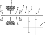
Because electrically driven speed change of the prior art mechanism often because complex structure, configuration are compact inadequately, often is inappropriate for and in many occasions, uses and increased cost.For example, limited it and needed the use in the electronlmobil of compact layout at some.As shown in fig. 1; Publication number is that the one Chinese patent application of CN101204924A discloses a kind of electrically driven speed change device, and it comprises electrical motor 3, motor main shaft 11, overriding clutch 4, low speed gear group 5, high speed gear group 6, power take-off shaft 7, low speed input shaft 9, high speed input shaft 10 and ordinary clutch 12.In this electrically driven speed change device; The power of electrical motor 3 is through motor main shaft 11 outputs; One end of motor main shaft 11 is connected to power take-off shaft 7 through overriding clutch 4, low speed input shaft 9 and low speed gear group 5 successively, and the other end is connected to power take-off shaft 7 through ordinary clutch 12, high speed input shaft 10 and high speed gear group 6 successively.Can find out that though this electric driver has been realized two grades of drivings of battery-driven car, structure is complicated, use at least two power-transfer clutchs (overriding clutch 4 and ordinary clutch 12), increase cost.
[summary of the invention]
In order to address the above problem, to the purpose of this invention is to provide a kind of simple, efficient, compact, cost-effective vehicle electricity consumption and drive transmission system.
Drive transmission system according to the invention provides a kind of vehicle electricity consumption.This vehicle electricity consumption drives transmission system and comprises motor and transmission device; Said transmission device comprises input shaft, speed-changing mechanism, tween drive shaft, speed reduction gearing and output shaft; Said motor comprises stator and rotor; Said rotor is connected with said input shaft, and said input shaft is connected to said tween drive shaft through said speed-changing mechanism, and said tween drive shaft is connected to said output shaft through said speed reduction gearing; Wherein, said speed-changing mechanism comprises parallel-axes gears group and synchro and realizes gear shift through synchro.Vehicle electricity consumption through this set drives transmission system, has saved power-transfer clutch, through synchro gear shift easily, realizes two grades of transmissions and more grades of transmissions easily; Can realize reverse gear easily again through motor being carried out suitable control, save the idle pulley for realizing that the transmission switching-over is provided with in the general vehicle, provide cost savings effectively, simplify the structure.
Alternatively, drive in the transmission system in above-mentioned vehicle electricity consumption, said input shaft and said output shaft coaxial arrangement, and said input shaft is hollow shaft, said output sleeve is in said input shaft.Vehicle electricity consumption through this set drives change speed gear box, has saved the occupied space of transmission system further, makes structure compact more, can satisfy the space requirement of small-sized and compact sedan etc.
Alternatively, drive in the transmission system in above-mentioned vehicle electricity consumption, said speed reduction gearing comprises diff, and said output shaft is one of semiaxis of said diff.Vehicle electricity consumption through this set drives transmission system, can realize the differential output of two semiaxis through diff, with under the different running statees that are implemented in vehicle to the different demands of rotating speed, takeoff output.For example, when this diff is center differential, promptly can realize the transmission forward and the different rotating speeds of transmission backward through semiaxis; The semiaxis of this diff also can rotate in order to the differential of two front-wheels of direct realization or trailing wheel.
Alternatively, drive in the transmission system, when Parking, realize braking during standstill through the housing of the said diff of locking in above-mentioned vehicle electricity consumption.Vehicle electricity consumption through this set drives transmission system, promptly can when vehicle is in the Parking state or goes at a slow speed, realize the braking to differential drive gear through the housing of the said diff of locking, so that vehicle gets into the braking during standstill state.
Alternatively, drive in the transmission system in above-mentioned vehicle electricity consumption, said speed-changing mechanism comprises two groups of parallel-axes gears groups and a synchro that is arranged between said two groups of parallel-axes gears groups.Vehicle electricity consumption through this set drives change speed gear box, can realize that easily the vehicle electricity consumption drives two grades of speed changes of change speed gear box with minimum gear cluster, minimum synchro.
Alternatively, drive in the transmission system in above-mentioned vehicle electricity consumption, said synchro is installed on the said input shaft.
Alternatively, drive in the transmission system in above-mentioned vehicle electricity consumption, said synchro is installed on the said tween drive shaft.
Alternatively, drive in the transmission system in above-mentioned vehicle electricity consumption, the gear shift of said synchro realizes through gear shifting drive motor driving, hydraulic-driven or manual actuation.
Alternatively, drive in the transmission system in above-mentioned vehicle electricity consumption, under the situation of gear shift through gear shifting drive motor driving realization of said synchro, said gear shifting drive motor is a servomotor.Vehicle electricity consumption through this set drives transmission system, and the driving through servomotor realization synchro makes gear changing mode convenient, smooth and easy.
Alternatively, drive in the transmission system in above-mentioned vehicle electricity consumption, under the situation of gear shift through the manual actuation realization of said synchro, it realizes that mechanism is manual drag-line.Vehicle electricity consumption through this set drives transmission system because connect manually that Cable Structure is simple, driving efficiency good, easy to operate, make Vehicular shift convenient, smooth and easy.
Alternatively, drive in the transmission system in above-mentioned vehicle electricity consumption, said motor is integrated in the vehicle gear box with said transmission device.Vehicle electricity consumption through this set drives transmission system, makes electrically driven speed change device good integrity, structure compact, more safe and reliable more.
Alternatively, drive in the transmission system in above-mentioned vehicle electricity consumption, said transmission device is integrated in the vehicle gear box, and said motor is arranged on outside the vehicle gear box.Vehicle electricity consumption through this set drives transmission system, can directly use external motor device, and needn't motor be designed again, make, thereby simplify design, manufacturing process and cost.
[description of drawings]
With reference to accompanying drawing, disclosure of the present invention will be more obvious.Should understand, these accompanying drawings only are used for illustrative purposes, and are not to be intended to protection scope of the present invention is constituted restriction.Among the figure:
Fig. 1 shows the electrically driven speed change schematic representation of apparatus according to prior art;
Fig. 2 shows the scheme drawing that the vehicle according to the invention electricity consumption drives first embodiment of transmission system;
Fig. 3 shows the scheme drawing that the vehicle according to the invention electricity consumption drives second embodiment of transmission system;
Fig. 4 shows the scheme drawing that the vehicle according to the invention electricity consumption drives the 3rd embodiment of transmission system;
Fig. 5 shows the scheme drawing that the vehicle according to the invention electricity consumption drives the 4th embodiment of transmission system;
Fig. 6 shows the scheme drawing that the vehicle according to the invention electricity consumption drives the 5th embodiment of transmission system; And
Fig. 7 shows the scheme drawing that the vehicle according to the invention electricity consumption drives the 6th embodiment of transmission system.
Parts and label list
| 3 | |
| 4 | Overriding |
| 5 | The low |
| 6 | The high speed gear group |
| 7 | Power take- |
| 9 | The low |
| 10 | The high |
| 11 | Motor |
| 12 | |
| 100、200、300、400、500、600 | The vehicle electricity consumption drives |
| 110、210、310、410、510、610 | Motor |
| 111、211、311、411、511、611 | |
| 120、220、320、420、520、620 | |
| 121、221、321、421、521、621 | |
| 122、222、322、422、522、622 | Tween drive |
| 524、624 | Semiaxis |
| 525、625 | Diff |
| 123、223、323、423、523、6230 | Output |
| 130、230、330、430、530、630 | Speed-changing |
| 131、231、331、431、531、631 | Gear cluster |
| 132、232、332、432、532、632 | Synchro |
| 133、233、333、433、533、633 | Gear |
| 140、240、340、440、540、640 | Speed reduction gearing |
[specific embodiment]
The specific embodiment of the present invention at length is described with reference to the accompanying drawings.Similar Reference numeral is used for the similar technical characterictic of mark in the accompanying drawing.Following explanation only is an illustrative, exemplary, though the specific embodiment wherein according to the present invention is illustrated, should understand, and also will fall within protection scope of the present invention at some modification embodiments.
First embodiment
Fig. 2 shows the scheme drawing that the vehicle according to the invention electricity consumption drives first embodiment of transmission system.In Fig. 2, represent with Reference numeral 100 generally according to the vehicle electricity consumption driving transmission system of this first embodiment.As can be seen from the figure, the vehicle electricity consumption driving transmission system 100 according to this first embodiment comprises motor 110 and transmission device 120.Motor 110 is the stator of motor 110 for representing with the part with hatching in its periphery, and week is the rotor 111 of motor 110 in it.Transmission device 120 is illustrated in the curvilinear frame (itself does not belong to the part of apparatus of the present invention this curve); It comprises input shaft 121, speed-changing mechanism 130, tween drive shaft 122, speed reduction gearing 140 and output shaft 123; Motor 110 comprises stator and rotor; The rotor 111 of motor 110 is connected (for example for be wholely set or device such as bolt connects) with input shaft 121, input shaft 121 is connected to tween drive shaft 122 through speed-changing mechanism 130, and tween drive shaft 122 is connected to output shaft 123 through speed reduction gearing 140.Speed-changing mechanism 130 is illustrated in the frame of broken lines respectively with speed reduction gearing 140.Vehicle electricity consumption at this first embodiment drives in the transmission system 100, and speed-changing mechanism 130 comprises that parallel-axes gears group 131,133 realizes gear shift with synchro 132 and through synchro 132 (for example through the different gear cluster 131,133 of engagement).
In the example of this first embodiment; The gear cluster speed-changing mechanism (speed-changing mechanism 130) that this vehicle electricity consumption drives transmission system 100 can comprise that 131,133 and one of two groups of parallel-axes gears groups are arranged on the synchro 132 between said two groups of parallel-axes gears groups; Like this, can realize gear shift through synchro 132 with different gear cluster engagements; The synchro 132 that this vehicle electricity consumption drives transmission system 100 can be constant pressure synchronizer, inertial type of synchronizer or boosting-type synchro voluntarily; Undoubtedly, the those skilled in the art can expect other form of synchronization device or gearshift under teaching of the present invention.Because synchro, gear cluster, the pairing of transmission shaft, fit are known by those skilled in the art, so repeat no more at this; The synchro 132 that this vehicle electricity consumption drives transmission system 100 can be installed on the said input shaft 121; This vehicle electricity consumption drives the gear shift of the synchro 132 of transmission system 100 can pass through gear shifting drive motor driving, hydraulic-driven or manual actuation realization; The gear shift that drives the synchro 132 of transmission system 100 in this vehicle electricity consumption drives under the situation about realizing through gear shifting drive motor, and said gear shifting drive motor can be all kinds of motors (not shown) such as servomotor, DC machine, stepping motor; The gear shift that drives the synchro 132 of transmission system 100 in this vehicle electricity consumption is passed through under the situation of manual actuation realization, and it realizes that mechanism can be manual drag-line (not shown); Tween drive shaft 122 and 140 of the speed reduction gearings between the output shaft 123 that this vehicle electricity consumption drives transmission system 100 can be gear transmission, strap drive or chain-driving; The motor 110 that this vehicle electricity consumption drives transmission system 100 can be integrated in the vehicle gear box with transmission device 120, and perhaps transmission device 120 is integrated in the vehicle gear box and motor 110 is arranged on outside the vehicle gear box.
Should be appreciated that in the example of said first embodiment, the technical characterictic that is limited is exemplary, illustrative in the above, can be equal to or similar modification it.For example; Though wherein to comprise that the gear cluster speed-changing mechanism that 131,133 and one of two groups of parallel-axes gears groups are arranged on the synchro 132 between said two groups of parallel-axes gears groups is an example; But; Gear cluster number in this gear cluster speed-changing mechanism (speed-changing mechanism 130) also can be more than two groups, and the number of synchro also can be more than one and/or not be arranged between two gears but be separately positioned on the not homonymy of gear cluster.
Second embodiment
Fig. 3 shows the scheme drawing that the vehicle according to the invention electricity consumption drives second embodiment of transmission system.In Fig. 3, represent with Reference numeral 200 generally according to the vehicle electricity consumption driving transmission system of this second embodiment.As can be seen from the figure, the vehicle electricity consumption driving transmission system 200 according to this second embodiment comprises motor 210 and transmission device 220.Motor 210 is the stator of motor 210 for representing with the part with hatching in its periphery, and week is the rotor 211 of motor 210 in it.Transmission device 220 is illustrated in the curvilinear frame (itself does not belong to the part of apparatus of the present invention this curve); It comprises input shaft 221, speed-changing mechanism 230, tween drive shaft 222, speed reduction gearing 240 and output shaft 223; Motor 210 comprises stator and rotor; The rotor 211 of motor 210 is connected (for example for be wholely set or device such as bolt connects) with input shaft 221, input shaft 221 is connected to tween drive shaft 222 through speed-changing mechanism 230, and tween drive shaft 222 is connected to output shaft 223 through speed reduction gearing 240.Speed-changing mechanism 230 is illustrated in the frame of broken lines respectively with speed reduction gearing 240.Vehicle electricity consumption at this second embodiment drives in the transmission system 200, and speed-changing mechanism 230 comprises that parallel-axes gears group 231,233 realizes gear shift with synchro 232 and through synchro 232 (for example through the different gear cluster 231,233 of engagement).
In the example of this second embodiment; The gear cluster speed-changing mechanism (speed-changing mechanism 230) that this vehicle electricity consumption drives transmission system 200 can comprise that 231,233 and one of two groups of parallel-axes gears groups are arranged on the synchro 232 between said two groups of parallel-axes gears groups; Like this, can realize gear shift through synchro 232 with different gear cluster engagements; The synchro 232 that this vehicle electricity consumption drives transmission system 200 can be constant pressure synchronizer, inertial type of synchronizer or boosting-type synchro voluntarily; Undoubtedly, the those skilled in the art can expect other form of synchronization device or gearshift under teaching of the present invention.Because synchro, gear cluster, the pairing of transmission shaft, fit are known by those skilled in the art, so repeat no more at this; The synchro 232 that this vehicle electricity consumption drives transmission system 200 can be installed on the said tween drive shaft 222; This vehicle electricity consumption drives the gear shift of the synchro 232 of transmission system 200 can pass through gear shifting drive motor driving, hydraulic-driven or manual actuation realization; The gear shift that drives the synchro 232 of transmission system 200 in this vehicle electricity consumption drives under the situation about realizing through gear shifting drive motor, and said gear shifting drive motor can be all kinds of motors (not shown) such as servomotor, DC machine, stepping motor; The gear shift that drives the synchro 232 of transmission system 200 in this vehicle electricity consumption is passed through under the situation of manual actuation realization, and it realizes that mechanism can be manual drag-line (not shown); Tween drive shaft 222 and 240 of the speed reduction gearings between the output shaft 223 that this vehicle electricity consumption drives transmission system 200 can be gear transmission, strap drive or chain-driving; The motor 210 that this vehicle electricity consumption drives transmission system 200 can be integrated in the vehicle gear box with transmission device 220, and perhaps transmission device 220 is integrated in the vehicle gear box and motor 210 is arranged on outside the vehicle gear box.
Should be appreciated that in the example of said second embodiment, the technical characterictic that is limited is exemplary, illustrative in the above, can be equal to or similar modification it.For example; Though wherein to comprise that the gear cluster speed-changing mechanism that 231,233 and one of two groups of gears are arranged on the synchro 232 between said two groups of gears is an example; But; Gear cluster number in this gear cluster speed-changing mechanism (speed-changing mechanism 130) also can be more than two groups, and the number of synchro also can be more than one and/or not be arranged between two gears but be separately positioned on the not homonymy of gear cluster.
The 3rd embodiment
Fig. 4 shows the scheme drawing that the vehicle according to the invention electricity consumption drives the 3rd embodiment of transmission system.In Fig. 4, represent with Reference numeral 300 generally according to the vehicle electricity consumption driving transmission system of this 3rd embodiment.As can be seen from the figure, the vehicle electricity consumption driving transmission system 300 according to this 3rd embodiment comprises motor 310 and transmission device 320.Motor 310 is the stator of motor 310 for representing with the part with hatching in its periphery, and week is the rotor 311 of motor 310 in it.Transmission device 320 is illustrated in the curvilinear frame (itself does not belong to the part of apparatus of the present invention this curve); It comprises input shaft 321, speed-changing mechanism 330, tween drive shaft 322, speed reduction gearing 340 and output shaft 323; Input shaft 321 and output shaft 323 coaxial arrangement; And input shaft 321 is a hollow shaft, and output shaft 323 is enclosed within the input shaft 321.Motor 310 comprises stator and rotor; The rotor 311 of motor 310 is connected (for example for be wholely set or device such as bolt connects) with input shaft 321; Input shaft 321 is connected to tween drive shaft 322 through speed-changing mechanism 330, and tween drive shaft 322 is connected to output shaft 323 through speed reduction gearing 340.Speed-changing mechanism 330 is illustrated in the frame of broken lines respectively with speed reduction gearing 340.Vehicle electricity consumption at this 3rd embodiment drives in the transmission system 300, and speed-changing mechanism 330 comprises that parallel-axes gears group 331,333 realizes gear shift with synchro 332 and through synchro 332 (for example through the different gear cluster 331,333 of engagement).
In the example of this 3rd embodiment; The gear cluster speed-changing mechanism (speed-changing mechanism 330) that this vehicle electricity consumption drives transmission system 300 can comprise that 331,333 and one of two groups of parallel-axes gears groups are arranged on the synchro 332 between said two groups of parallel-axes gears groups; Like this, can realize gear shift through synchro 332 with different gear cluster engagements; The synchro 332 that this vehicle electricity consumption drives transmission system 300 can be constant pressure synchronizer, inertial type of synchronizer or boosting-type synchro voluntarily; Undoubtedly, the those skilled in the art can expect other form of synchronization device or gearshift under teaching of the present invention.Because synchro, gear cluster, the pairing of transmission shaft, fit are known by those skilled in the art, so repeat no more at this; The synchro 332 that this vehicle electricity consumption drives transmission system 300 can be installed on the said input shaft 321; This vehicle electricity consumption drives the gear shift of the synchro 332 of transmission system 300 can pass through gear shifting drive motor driving, hydraulic-driven or manual actuation realization; The gear shift that drives the synchro 332 of transmission system 300 in this vehicle electricity consumption drives under the situation about realizing through gear shifting drive motor, and said gear shifting drive motor can be all kinds of motors (not shown) such as servomotor, DC machine, stepping motor; The gear shift that drives the synchro 332 of transmission system 300 in this vehicle electricity consumption is passed through under the situation of manual actuation realization, and it realizes that mechanism can be manual drag-line (not shown); Tween drive shaft 322 and 340 of the speed reduction gearings between the output shaft 323 that this vehicle electricity consumption drives transmission system 300 can be gear transmission, strap drive or chain-driving; The motor 310 that this vehicle electricity consumption drives transmission system 300 can be integrated in the vehicle gear box with transmission device 320, and perhaps transmission device 320 is integrated in the vehicle gear box and motor 310 is arranged on outside the vehicle gear box.
Should be appreciated that in the example of said the 3rd embodiment, the technical characterictic that is limited is exemplary, illustrative in the above, can be equal to or similar modification it.For example; Though wherein to comprise that the gear cluster speed-changing mechanism that 331,333 and one of two groups of parallel-axes gears groups are arranged on the synchro 332 between said two groups of parallel-axes gears groups is an example; But; Gear cluster number in this gear cluster speed-changing mechanism (speed-changing mechanism 330) also can be more than two groups, and the number of synchro also can be more than one and/or not be arranged between two gears but be separately positioned on the not homonymy of gear cluster.
The 4th embodiment
Fig. 5 shows the scheme drawing that the vehicle according to the invention electricity consumption drives the 4th embodiment of transmission system.In Fig. 5, represent with Reference numeral 400 generally according to the vehicle electricity consumption driving transmission system of this 4th embodiment.As can be seen from the figure, the vehicle electricity consumption driving transmission system 400 according to this 4th embodiment comprises motor 410 and transmission device 420.Motor 410 is the stator of motor 410 for representing with the part with hatching in its periphery, and week is the rotor 411 of motor 410 in it.Transmission device 420 is illustrated in the curvilinear frame (itself does not belong to the part of apparatus of the present invention this curve); It comprises input shaft 421, speed-changing mechanism 430, tween drive shaft 422, speed reduction gearing 440 and output shaft 423; Input shaft 421 and output shaft 423 coaxial arrangement; And input shaft 421 is a hollow shaft, and output shaft 423 is enclosed within the input shaft 421.Motor 110 comprises stator and rotor; The rotor 411 of motor 410 is connected (for example for be wholely set or device such as bolt connects) with input shaft 421; Input shaft 421 is connected to tween drive shaft 422 through speed-changing mechanism 430, and tween drive shaft 422 is connected to output shaft 423 through speed reduction gearing 440.Speed-changing mechanism 430 is illustrated in the frame of broken lines respectively with speed reduction gearing 440.Vehicle electricity consumption at this 4th embodiment drives in the transmission system 400, and speed-changing mechanism 430 comprises that parallel-axes gears group 431,433 realizes gear shift with synchro 432 and through synchro 432 (for example through the different gear cluster 431,433 of engagement).
In the example of this 4th embodiment; The gear cluster speed-changing mechanism (speed-changing mechanism 430) that this vehicle electricity consumption drives transmission system 400 can comprise that 431,433 and one of two groups of parallel-axes gears groups are arranged on the synchro 432 between said two groups of parallel-axes gears groups; Like this, can realize gear shift through synchro 432 with different gear cluster engagements; The synchro 432 that this vehicle electricity consumption drives transmission system 400 can be constant pressure synchronizer, inertial type of synchronizer or boosting-type synchro voluntarily; Undoubtedly, the those skilled in the art can expect other form of synchronization device or gearshift under teaching of the present invention.Because synchro, gear cluster, the pairing of transmission shaft, fit are known by those skilled in the art, so repeat no more at this; The synchro 432 that this vehicle electricity consumption drives transmission system 400 can be installed on the said tween drive shaft 422; This vehicle electricity consumption drives the gear shift of the synchro 432 of transmission system 400 can pass through gear shifting drive motor driving, hydraulic-driven or manual actuation realization; The gear shift that drives the synchro 432 of transmission system 400 in this vehicle electricity consumption drives under the situation about realizing through gear shifting drive motor, and said gear shifting drive motor can be all kinds of motors (not shown) such as servomotor, DC machine, stepping motor; The gear shift that drives the synchro 432 of transmission system 400 in this vehicle electricity consumption is passed through under the situation of manual actuation realization, and it realizes that mechanism can be manual drag-line (not shown); Tween drive shaft 422 and 440 of the speed reduction gearings between the output shaft 423 that this vehicle electricity consumption drives transmission system 400 can be gear transmission, strap drive or chain-driving; The motor 410 that this vehicle electricity consumption drives transmission system 400 can be integrated in the vehicle gear box with transmission device 420, and perhaps transmission device 420 is integrated in the vehicle gear box and motor 410 is arranged on outside the vehicle gear box.
Should be appreciated that in the example of said the 4th embodiment, the technical characterictic that is limited is exemplary, illustrative in the above, can be equal to or similar modification it.For example; Though wherein to comprise that the gear cluster speed-changing mechanism that 431,433 and one of two groups of parallel-axes gears groups are arranged on the synchro 432 between said two groups of parallel-axes gears groups is an example; But; Gear cluster number in this gear cluster speed-changing mechanism (speed-changing mechanism 430) also can be more than two groups, and the number of synchro also can be more than one and/or not be arranged between two gears but be separately positioned on the not homonymy of gear cluster.
The 5th embodiment
Fig. 6 shows the scheme drawing that the vehicle according to the invention electricity consumption drives the 5th embodiment of transmission system.In Fig. 6, represent with Reference numeral 500 generally according to the vehicle electricity consumption driving transmission system of this 5th embodiment.As can be seen from the figure, the vehicle electricity consumption driving transmission system 500 according to this 5th embodiment comprises motor 510 and transmission device 520.Motor 510 is the stator of motor 510 for representing with the part with hatching in its periphery, and week is the rotor 511 of motor 510 in it.Transmission device 520 is illustrated in the curvilinear frame (itself does not belong to the part of apparatus of the present invention this curve); It comprises input shaft 521, speed-changing mechanism 530, tween drive shaft 522, speed reduction gearing 540 and output shaft 523; Input shaft 521 and output shaft 523 coaxial arrangement; And input shaft 521 is a hollow shaft, and output shaft 523 is enclosed within the input shaft 521.Motor 510 comprises stator and rotor; The rotor 511 of motor 510 is connected (for example for be wholely set or device such as bolt connects) with input shaft 521; Input shaft 521 is connected to tween drive shaft 522 through speed-changing mechanism 530, and tween drive shaft 522 is connected to output shaft 523 through speed reduction gearing 540.Speed-changing mechanism 530 is illustrated in the frame of broken lines respectively with speed reduction gearing 540.Vehicle electricity consumption at this 5th embodiment drives in the transmission system 500, and speed-changing mechanism 530 comprises that parallel-axes gears group 531,533 realizes gear shift with synchro 532 and through synchro 532 (for example through the different gear cluster 531,533 of engagement).Speed reduction gearing 540 comprises diff 525, and output shaft 523 is one of semiaxis of said diff (for example its another semiaxis can be the semiaxis 524 shown in the figure).In a preferred embodiment; When Parking, can realize braking during standstill through the housing of locking differential 525; For example; Can be provided with stopping element (not shown) on the housing of diff 525, be used for the power transmission of locking differential 525, can realize the braking during standstill (perhaps when vehicle goes slowly, carrying out braking during standstill) when vehicle stops so effectively.In another preferred embodiment, stopping element is ratchet (not shown).
In the example of this 5th embodiment; The gear cluster speed-changing mechanism (speed-changing mechanism 530) that this vehicle electricity consumption drives transmission system 500 can comprise that 531,533 and one of two groups of parallel-axes gears groups are arranged on the synchro 532 between said two groups of parallel-axes gears groups; Like this, can realize gear shift through synchro 532 with different gear cluster engagements; The synchro 532 that this vehicle electricity consumption drives transmission system 500 can be constant pressure synchronizer, inertial type of synchronizer or boosting-type synchro voluntarily; Undoubtedly, the those skilled in the art can expect other form of synchronization device or gearshift under teaching of the present invention.Because synchro, gear cluster, the pairing of transmission shaft, fit are known by those skilled in the art, so repeat no more at this; The synchro 532 that this vehicle electricity consumption drives transmission system 500 can be installed on the said input shaft 521; This vehicle electricity consumption drives the gear shift of the synchro 532 of transmission system 500 can pass through gear shifting drive motor driving, hydraulic-driven or manual actuation realization; The gear shift that drives the synchro 532 of transmission system 500 in this vehicle electricity consumption drives under the situation about realizing through gear shifting drive motor, and said gear shifting drive motor can be all kinds of motors (not shown) such as servomotor, DC machine, stepping motor; The gear shift that drives the synchro 532 of transmission system 500 in this vehicle electricity consumption is passed through under the situation of manual actuation realization, and it realizes that mechanism can be manual drag-line (not shown); Tween drive shaft 522 and 540 of the speed reduction gearings between the output shaft 523 that this vehicle electricity consumption drives transmission system 500 can be gear transmission, strap drive or chain-driving; The motor 510 that this vehicle electricity consumption drives transmission system 500 can be integrated in the vehicle gear box with transmission device 520, and perhaps transmission device 520 is integrated in the vehicle gear box and motor 510 is arranged on outside the vehicle gear box.
Should be appreciated that in the example of said the 5th embodiment, the technical characterictic that is limited is exemplary, illustrative in the above, can be equal to or similar modification it.For example; Though wherein to comprise that the gear cluster speed-changing mechanism that 531,533 and one of two groups of gears are arranged on the synchro 532 between said two groups of gears is an example; But; Gear cluster number in this gear cluster speed-changing mechanism (speed-changing mechanism 530) also can be more than two groups, and the number of synchro also can be more than one and/or not be arranged between two gears but be separately positioned on the not homonymy of gear cluster.
The 6th embodiment
Fig. 7 shows the scheme drawing that the vehicle according to the invention electricity consumption drives the 6th embodiment of transmission system.In Fig. 7, represent with Reference numeral 600 generally according to the vehicle electricity consumption driving transmission system of this 6th embodiment.As can be seen from the figure, the vehicle electricity consumption driving transmission system 600 according to this 6th embodiment comprises motor 610 and transmission device 620.Motor 610 is the stator of motor 610 for representing with the part with hatching in its periphery, and week is the rotor 611 of motor 610 in it.Transmission device 620 is illustrated in the curvilinear frame (itself does not belong to the part of apparatus of the present invention this curve); It comprises input shaft 621, speed-changing mechanism 630, tween drive shaft 622, speed reduction gearing 640 and output shaft 623; Input shaft 621 and output shaft 623 coaxial arrangement; And input shaft 621 is a hollow shaft, and output shaft 623 is enclosed within the input shaft 621.Motor 610 comprises stator and rotor; The rotor 611 of motor 610 is connected (for example for be wholely set or device such as bolt connects) with input shaft 621; Input shaft 621 is connected to tween drive shaft 622 through speed-changing mechanism 630, and tween drive shaft 622 is connected to output shaft 623 through speed reduction gearing 640.Speed-changing mechanism 630 is illustrated in the frame of broken lines respectively with speed reduction gearing 640.Vehicle electricity consumption at this 6th embodiment drives in the transmission system 600, and speed-changing mechanism 630 comprises that parallel-axes gears group 631,633 realizes gear shift with synchro 632 and through synchro 632 (for example through the different gear cluster 631,633 of engagement).Speed reduction gearing 640 comprises diff 625, and output shaft 623 is one of semiaxis of said diff (for example its another semiaxis can be the semiaxis 624 shown in the figure).In a preferred embodiment; When Parking, can realize braking during standstill through the housing of locking differential 625; For example; Can be provided with stopping element (not shown) on the housing of diff 625, be used for the power transmission of locking differential 625, can realize the braking during standstill (perhaps when vehicle goes slowly, carrying out braking during standstill) when vehicle stops so effectively.In another preferred embodiment, stopping element is ratchet (not shown).
In the example of this 6th embodiment; The gear cluster speed-changing mechanism (speed-changing mechanism 630) that this vehicle electricity consumption drives transmission system 600 can comprise that 631,633 and one of two groups of parallel-axes gears groups are arranged on the synchro 632 between said two groups of parallel-axes gears groups; Like this, can realize gear shift through synchro 632 with different gear cluster engagements; The synchro 632 that this vehicle electricity consumption drives transmission system 600 can be constant pressure synchronizer, inertial type of synchronizer or boosting-type synchro voluntarily; Undoubtedly, the those skilled in the art can expect other form of synchronization device or gearshift under teaching of the present invention.Because synchro, gear cluster, the pairing of transmission shaft, fit are known by those skilled in the art, so repeat no more at this; The synchro 632 that this vehicle electricity consumption drives transmission system 600 can be installed on the said tween drive shaft 622; This vehicle electricity consumption drives the gear shift of the synchro 632 of transmission system 600 can pass through gear shifting drive motor driving, hydraulic-driven or manual actuation realization; The gear shift that drives the synchro 632 of transmission system 600 in this vehicle electricity consumption drives under the situation about realizing through gear shifting drive motor, and said gear shifting drive motor can be all kinds of motors (not shown) such as servomotor, DC machine, stepping motor; The gear shift that drives the synchro 632 of transmission system 600 in this vehicle electricity consumption is passed through under the situation of manual actuation realization, and it realizes that mechanism can be manual drag-line (not shown); Tween drive shaft 622 and 640 of the speed reduction gearings between the output shaft 623 that this vehicle electricity consumption drives transmission system 600 can be gear transmission, strap drive or chain-driving; The motor 610 that this vehicle electricity consumption drives transmission system 600 can be integrated in the vehicle gear box with transmission device 620, and perhaps transmission device 620 is integrated in the vehicle gear box and motor 610 is arranged on outside the vehicle gear box.
Should be appreciated that in the example of said the 6th embodiment, the technical characterictic that is limited is exemplary, illustrative in the above, can be equal to or similar modification it.For example; Though wherein to comprise that the gear cluster speed-changing mechanism that 631,633 and one of two groups of gears are arranged on the synchro 632 between said two groups of gears is an example; But; Gear cluster number in this gear cluster speed-changing mechanism (speed-changing mechanism 630) also can be more than two groups, and the number of synchro also can be more than one and/or not be arranged between two gears but be separately positioned on the not homonymy of gear cluster.
As stated, specify with reference to the accompanying drawing specific embodiments of the invention.Under situation about not deviating from according to the spirit and scope of the present invention; The those skilled in the art can retrofit and modification to these embodiments; For example; Thereby the those skilled in the art can reconfigure the different techniques characteristic in the different embodiments and constitute new technical scheme; But should understand, these new technical schemes also are equal to undoubtedly and directly have been documented in this specification sheets and repeat no more, and they also fall within by in the determined protection domain of appending claims.The application is intended to that the detail of these embodiments limits protection scope of the present invention in the service instructions.
Claims (12)
1. a vehicle electricity consumption drives transmission system; It is characterized in that said vehicle electricity consumption drives transmission system and comprises motor and transmission device, said transmission device comprises input shaft, speed-changing mechanism, tween drive shaft, speed reduction gearing and output shaft; Said motor comprises stator and rotor; Said rotor is connected with said input shaft, and said input shaft is connected to said tween drive shaft through said speed-changing mechanism, and said tween drive shaft is connected to said output shaft through said speed reduction gearing; Wherein, said speed-changing mechanism comprises parallel-axes gears group and synchro and realizes gear shift through synchro.
2. vehicle electricity consumption as claimed in claim 1 drives transmission system, it is characterized in that, and said input shaft and said output shaft coaxial arrangement, and said input shaft is hollow shaft, said output sleeve is in said input shaft.
3. vehicle electricity consumption as claimed in claim 1 drives transmission system, it is characterized in that said speed reduction gearing comprises diff, and said output shaft is one of semiaxis of said diff.
4. vehicle electricity consumption as claimed in claim 3 drives transmission system, it is characterized in that, when Parking, realizes braking during standstill through the housing of the said diff of locking.
5. drive transmission system like each described vehicle electricity consumption in the claim 1 to 4, it is characterized in that said speed-changing mechanism comprises two groups of parallel-axes gears groups and a synchro that is arranged between said two groups of parallel-axes gears groups.
6. drive transmission system like each described vehicle electricity consumption in the claim 1 to 4, it is characterized in that said synchro is installed on the said input shaft.
7. drive transmission system like each described vehicle electricity consumption in the claim 1 to 4, it is characterized in that said synchro is installed on the said tween drive shaft.
8. drive transmission system like each described vehicle electricity consumption in the claim 1 to 4, it is characterized in that the gear shift of said synchro realizes through gear shifting drive motor driving, hydraulic-driven or manual actuation.
9. vehicle electricity consumption as claimed in claim 8 drives transmission system, it is characterized in that, under the situation of gear shift through gear shifting drive motor driving realization of said synchro, said gear shifting drive motor is a servomotor.
10. vehicle electricity consumption as claimed in claim 8 drives transmission system, it is characterized in that, under the situation of gear shift through the manual actuation realization of said synchro, it realizes that mechanism is manual drag-line.
11. drive transmission system like each described vehicle electricity consumption in the claim 1 to 4, it is characterized in that said motor is integrated in the vehicle gear box with said transmission device.
12. drive transmission system like each described vehicle electricity consumption in the claim 1 to 4, it is characterized in that said transmission device is integrated in the vehicle gear box, and said motor be arranged on outside the vehicle gear box.
Priority Applications (1)
| Application Number | Priority Date | Filing Date | Title |
|---|---|---|---|
| CN2010102534058A CN102371893A (en) | 2010-08-13 | 2010-08-13 | Electrically-driven speed change device for vehicles |
Applications Claiming Priority (1)
| Application Number | Priority Date | Filing Date | Title |
|---|---|---|---|
| CN2010102534058A CN102371893A (en) | 2010-08-13 | 2010-08-13 | Electrically-driven speed change device for vehicles |
Publications (1)
| Publication Number | Publication Date |
|---|---|
| CN102371893A true CN102371893A (en) | 2012-03-14 |
Family
ID=45791337
Family Applications (1)
| Application Number | Title | Priority Date | Filing Date |
|---|---|---|---|
| CN2010102534058A Pending CN102371893A (en) | 2010-08-13 | 2010-08-13 | Electrically-driven speed change device for vehicles |
Country Status (1)
| Country | Link |
|---|---|
| CN (1) | CN102371893A (en) |
Cited By (27)
| Publication number | Priority date | Publication date | Assignee | Title |
|---|---|---|---|---|
| CN103075472A (en) * | 2013-02-18 | 2013-05-01 | 蔡国法 | Transmission case of electric vehicle |
| CN103423409A (en) * | 2012-05-24 | 2013-12-04 | 姜华 | Two-speed transmission in all-electric automobiles |
| CN103591224A (en) * | 2012-08-13 | 2014-02-19 | 姜华 | Drive mechanism for pure electric car two-speed driver |
| CN104179896A (en) * | 2013-05-28 | 2014-12-03 | 重庆铜川科技发展有限公司 | High-low gear conversion decelerator for electric vehicle |
| CN104455384A (en) * | 2014-10-13 | 2015-03-25 | 北京理工大学 | Electric drive system based on two-gear speed changing and coordinated gear shifting control method of electric drive system |
| CN105805303A (en) * | 2016-05-18 | 2016-07-27 | 山东理工大学 | Asynchronous motor and double-speed electromagnetic direct-drive transmission integration system |
| US9421966B2 (en) | 2014-10-20 | 2016-08-23 | Byd Company Limited | Hybrid vehicle and shifting control method and power transmission system thereof |
| CN106015560A (en) * | 2016-05-18 | 2016-10-12 | 山东理工大学 | Permanent magnet synchronous motor and double-speed electromagnetic direct-drive transmission integrated power system |
| US9568066B2 (en) | 2014-09-10 | 2017-02-14 | Byd Company Limited | Power transmission system and vehicle comprising the same |
| US9568082B2 (en) | 2014-01-30 | 2017-02-14 | Byd Company Limited | Power transmission system for vehicle and vehicle comprising the same |
| US9566978B2 (en) | 2014-01-30 | 2017-02-14 | Byd Company Limited | Vehicle and drive control method for the same |
| US9568080B2 (en) | 2014-01-30 | 2017-02-14 | Byd Company Limited | Power transmission system for vehicle and vehicle comprising the same |
| US9568065B2 (en) | 2014-09-10 | 2017-02-14 | Byd Company Limited | Transmission unit, power transmission system and vehicle comprising the same |
| US9568081B2 (en) | 2014-01-30 | 2017-02-14 | Byd Company Limited | Power transmission system for vehicle and vehicle comprising the same |
| WO2017185901A1 (en) * | 2016-04-28 | 2017-11-02 | 舍弗勒技术股份两合公司 | Transaxle and two-speed drive module thereof |
| US9874266B2 (en) | 2014-09-10 | 2018-01-23 | Byd Company Limited | Power transmission system and vehicle comprising the same |
| US9919699B2 (en) | 2014-01-30 | 2018-03-20 | Byd Company Limited | Vehicle and method for controlling synchronizer of the same |
| US9944165B2 (en) | 2014-01-30 | 2018-04-17 | Byd Company Limited | Power transmission system for vehicle and vehicle comprising the same |
| CN108679172A (en) * | 2018-07-18 | 2018-10-19 | 樊朝晖 | A kind of coaxial straight line gear |
| CN108953537A (en) * | 2018-08-03 | 2018-12-07 | 东南大学 | A kind of modularization tandem type speed changer |
| CN109552037A (en) * | 2017-09-26 | 2019-04-02 | 舍弗勒技术股份两合公司 | Electric axle system and motor vehicle |
| WO2019141145A1 (en) * | 2018-01-19 | 2019-07-25 | 精进电动科技股份有限公司 | Longitudinally provided vehicle driving assembly having single power source |
| US10363806B2 (en) | 2014-01-30 | 2019-07-30 | Byd Company Limited | Power transmission system for vehicle and vehicle comprising the same |
| CN111022590A (en) * | 2020-01-03 | 2020-04-17 | 万向集团公司 | Transmission for electric automobile |
| CN111043258A (en) * | 2019-12-25 | 2020-04-21 | 广东博智林机器人有限公司 | Automatic speed change switching structure of gearbox and trowelling machine |
| US10670123B2 (en) | 2014-01-30 | 2020-06-02 | Byd Company Limited | Power transmission system for vehicle and vehicle comprising the same |
| CN113910889A (en) * | 2021-10-09 | 2022-01-11 | 义乌吉利自动变速器有限公司 | Transmission, hybrid drive device and vehicle |
Citations (5)
| Publication number | Priority date | Publication date | Assignee | Title |
|---|---|---|---|---|
| CN101204924A (en) * | 2006-12-19 | 2008-06-25 | 比亚迪股份有限公司 | Electric motor vehicle driving system |
| CN101292101A (en) * | 2005-10-19 | 2008-10-22 | 腓特烈斯港齿轮工厂股份公司 | Automatic transmission and shift control method for said transmission |
| CN101342867A (en) * | 2008-08-26 | 2009-01-14 | 同济大学 | Electric servodrive apparatus of hybrid automobile |
| CN101380892A (en) * | 2008-10-14 | 2009-03-11 | 山东时风(集团)有限责任公司 | Drive system of electric motor vehicle |
| CN201769685U (en) * | 2010-08-13 | 2011-03-23 | 上海捷能汽车技术有限公司 | Vehicular electric drive transmission |
-
2010
- 2010-08-13 CN CN2010102534058A patent/CN102371893A/en active Pending
Patent Citations (5)
| Publication number | Priority date | Publication date | Assignee | Title |
|---|---|---|---|---|
| CN101292101A (en) * | 2005-10-19 | 2008-10-22 | 腓特烈斯港齿轮工厂股份公司 | Automatic transmission and shift control method for said transmission |
| CN101204924A (en) * | 2006-12-19 | 2008-06-25 | 比亚迪股份有限公司 | Electric motor vehicle driving system |
| CN101342867A (en) * | 2008-08-26 | 2009-01-14 | 同济大学 | Electric servodrive apparatus of hybrid automobile |
| CN101380892A (en) * | 2008-10-14 | 2009-03-11 | 山东时风(集团)有限责任公司 | Drive system of electric motor vehicle |
| CN201769685U (en) * | 2010-08-13 | 2011-03-23 | 上海捷能汽车技术有限公司 | Vehicular electric drive transmission |
Cited By (32)
| Publication number | Priority date | Publication date | Assignee | Title |
|---|---|---|---|---|
| CN103423409A (en) * | 2012-05-24 | 2013-12-04 | 姜华 | Two-speed transmission in all-electric automobiles |
| CN103591224A (en) * | 2012-08-13 | 2014-02-19 | 姜华 | Drive mechanism for pure electric car two-speed driver |
| CN103075472B (en) * | 2013-02-18 | 2017-02-08 | 蔡国法 | Transmission case of electric vehicle |
| CN103075472A (en) * | 2013-02-18 | 2013-05-01 | 蔡国法 | Transmission case of electric vehicle |
| CN104179896A (en) * | 2013-05-28 | 2014-12-03 | 重庆铜川科技发展有限公司 | High-low gear conversion decelerator for electric vehicle |
| US10363806B2 (en) | 2014-01-30 | 2019-07-30 | Byd Company Limited | Power transmission system for vehicle and vehicle comprising the same |
| US9919699B2 (en) | 2014-01-30 | 2018-03-20 | Byd Company Limited | Vehicle and method for controlling synchronizer of the same |
| US10670123B2 (en) | 2014-01-30 | 2020-06-02 | Byd Company Limited | Power transmission system for vehicle and vehicle comprising the same |
| US9944165B2 (en) | 2014-01-30 | 2018-04-17 | Byd Company Limited | Power transmission system for vehicle and vehicle comprising the same |
| US9568081B2 (en) | 2014-01-30 | 2017-02-14 | Byd Company Limited | Power transmission system for vehicle and vehicle comprising the same |
| US9568082B2 (en) | 2014-01-30 | 2017-02-14 | Byd Company Limited | Power transmission system for vehicle and vehicle comprising the same |
| US9566978B2 (en) | 2014-01-30 | 2017-02-14 | Byd Company Limited | Vehicle and drive control method for the same |
| US9568080B2 (en) | 2014-01-30 | 2017-02-14 | Byd Company Limited | Power transmission system for vehicle and vehicle comprising the same |
| US9568065B2 (en) | 2014-09-10 | 2017-02-14 | Byd Company Limited | Transmission unit, power transmission system and vehicle comprising the same |
| US9568066B2 (en) | 2014-09-10 | 2017-02-14 | Byd Company Limited | Power transmission system and vehicle comprising the same |
| US9874266B2 (en) | 2014-09-10 | 2018-01-23 | Byd Company Limited | Power transmission system and vehicle comprising the same |
| CN104455384A (en) * | 2014-10-13 | 2015-03-25 | 北京理工大学 | Electric drive system based on two-gear speed changing and coordinated gear shifting control method of electric drive system |
| US9421966B2 (en) | 2014-10-20 | 2016-08-23 | Byd Company Limited | Hybrid vehicle and shifting control method and power transmission system thereof |
| WO2017185901A1 (en) * | 2016-04-28 | 2017-11-02 | 舍弗勒技术股份两合公司 | Transaxle and two-speed drive module thereof |
| CN107323255A (en) * | 2016-04-28 | 2017-11-07 | 舍弗勒技术股份两合公司 | Transaxle and its double speed drive module |
| US10808814B2 (en) | 2016-04-28 | 2020-10-20 | Schaeffler Technologies AG & Co. KG | Transaxle and two-speed drive module thereof |
| CN105805303A (en) * | 2016-05-18 | 2016-07-27 | 山东理工大学 | Asynchronous motor and double-speed electromagnetic direct-drive transmission integration system |
| CN106015560A (en) * | 2016-05-18 | 2016-10-12 | 山东理工大学 | Permanent magnet synchronous motor and double-speed electromagnetic direct-drive transmission integrated power system |
| CN109552037A (en) * | 2017-09-26 | 2019-04-02 | 舍弗勒技术股份两合公司 | Electric axle system and motor vehicle |
| WO2019141145A1 (en) * | 2018-01-19 | 2019-07-25 | 精进电动科技股份有限公司 | Longitudinally provided vehicle driving assembly having single power source |
| US11440400B2 (en) | 2018-01-19 | 2022-09-13 | Jing-Jin Electric Technologies Co., Ltd. | Longitudinally provided vehicle driving assembly having single power source |
| CN108679172A (en) * | 2018-07-18 | 2018-10-19 | 樊朝晖 | A kind of coaxial straight line gear |
| CN108953537A (en) * | 2018-08-03 | 2018-12-07 | 东南大学 | A kind of modularization tandem type speed changer |
| CN111043258A (en) * | 2019-12-25 | 2020-04-21 | 广东博智林机器人有限公司 | Automatic speed change switching structure of gearbox and trowelling machine |
| CN111022590A (en) * | 2020-01-03 | 2020-04-17 | 万向集团公司 | Transmission for electric automobile |
| CN113910889A (en) * | 2021-10-09 | 2022-01-11 | 义乌吉利自动变速器有限公司 | Transmission, hybrid drive device and vehicle |
| CN113910889B (en) * | 2021-10-09 | 2023-08-22 | 义乌吉利自动变速器有限公司 | Transmission, hybrid drive device, and vehicle |
Similar Documents
| Publication | Publication Date | Title |
|---|---|---|
| CN102371893A (en) | Electrically-driven speed change device for vehicles | |
| CN201769685U (en) | Vehicular electric drive transmission | |
| CN102069703B (en) | Electromechanical hybrid power mobile automatic transmission drive system | |
| CN100476253C (en) | Multimode transmission system of mixing dynamical automobile | |
| CN204340646U (en) | A kind of hybrid transmissions | |
| CN102107604A (en) | Hybrid driving system for automobile and gear operating method thereof | |
| CN1924400A (en) | Electrically variable hybrid transmission and powertrain | |
| CN104948716A (en) | Longitudinally-arranged dual-motor powered shifting transmission | |
| CN101780768A (en) | Two-speed automatic transmission for electric vehicle | |
| CN102490585A (en) | Automobile hybrid power assembly | |
| CN109318704B (en) | Electric drive transmission device | |
| CN114829174A (en) | Gearbox for an electric drive train | |
| CN203142374U (en) | Transmission of HEV (hybrid electric vehicle) | |
| CN201816450U (en) | Electromotion Mechanical Automated Transmission device and automobile using the same | |
| KR101008486B1 (en) | Transmission for electric vehicle | |
| CN113459790A (en) | Transverse hybrid power transmission and automobile | |
| CN103241114B (en) | Mixed power plant and comprise the automobile of this mixed power plant | |
| CN102673366B (en) | Integrated hybrid power driving device | |
| CN101793315A (en) | Mechanical and hydraulic combined power transmission mechanism | |
| CN201925422U (en) | Transmission system for automatic transmission of electromechanical hybrid electric vehicle | |
| CN110758083A (en) | New energy vehicle power system and control method thereof | |
| CN202827142U (en) | Double-rotor motor and electronic continuously variable transmission (CVT) device used for electric automobile | |
| KR101408465B1 (en) | Two-speed transmission for electric vehicle | |
| CN110758082B (en) | New energy vehicle power coupling device and control method thereof | |
| CN209257864U (en) | A kind of hybrid power system and its automobile |
Legal Events
| Date | Code | Title | Description |
|---|---|---|---|
| C06 | Publication | ||
| PB01 | Publication | ||
| C10 | Entry into substantive examination | ||
| SE01 | Entry into force of request for substantive examination | ||
| C12 | Rejection of a patent application after its publication | ||
| RJ01 | Rejection of invention patent application after publication |
Application publication date: 20120314 |