EP2993433B1 - Vortrocknungsvorrichtung für eine trocknungsanlage - Google Patents
Vortrocknungsvorrichtung für eine trocknungsanlage Download PDFInfo
- Publication number
- EP2993433B1 EP2993433B1 EP15178561.5A EP15178561A EP2993433B1 EP 2993433 B1 EP2993433 B1 EP 2993433B1 EP 15178561 A EP15178561 A EP 15178561A EP 2993433 B1 EP2993433 B1 EP 2993433B1
- Authority
- EP
- European Patent Office
- Prior art keywords
- air
- drying
- predrying
- drying plant
- dehumidifier
- Prior art date
- Legal status (The legal status is an assumption and is not a legal conclusion. Google has not performed a legal analysis and makes no representation as to the accuracy of the status listed.)
- Not-in-force
Links
Images

Classifications
-
- F—MECHANICAL ENGINEERING; LIGHTING; HEATING; WEAPONS; BLASTING
- F26—DRYING
- F26B—DRYING SOLID MATERIALS OR OBJECTS BY REMOVING LIQUID THEREFROM
- F26B1/00—Preliminary treatment of solid materials or objects to facilitate drying, e.g. mixing or backmixing the materials to be dried with predominantly dry solids
-
- F—MECHANICAL ENGINEERING; LIGHTING; HEATING; WEAPONS; BLASTING
- F26—DRYING
- F26B—DRYING SOLID MATERIALS OR OBJECTS BY REMOVING LIQUID THEREFROM
- F26B17/00—Machines or apparatus for drying materials in loose, plastic, or fluidised form, e.g. granules, staple fibres, with progressive movement
- F26B17/02—Machines or apparatus for drying materials in loose, plastic, or fluidised form, e.g. granules, staple fibres, with progressive movement with movement performed by belts carrying the materials; with movement performed by belts propelling the materials over stationary surfaces
- F26B17/04—Machines or apparatus for drying materials in loose, plastic, or fluidised form, e.g. granules, staple fibres, with progressive movement with movement performed by belts carrying the materials; with movement performed by belts propelling the materials over stationary surfaces the belts being all horizontal or slightly inclined
-
- F—MECHANICAL ENGINEERING; LIGHTING; HEATING; WEAPONS; BLASTING
- F26—DRYING
- F26B—DRYING SOLID MATERIALS OR OBJECTS BY REMOVING LIQUID THEREFROM
- F26B21/00—Arrangements for supplying or controlling air or other gases for drying solid materials or objects
- F26B21/20—Circulating air or gases in closed cycles, e.g. wholly within the drying enclosure
-
- F—MECHANICAL ENGINEERING; LIGHTING; HEATING; WEAPONS; BLASTING
- F26—DRYING
- F26B—DRYING SOLID MATERIALS OR OBJECTS BY REMOVING LIQUID THEREFROM
- F26B21/00—Arrangements for supplying or controlling air or other gases for drying solid materials or objects
- F26B21/30—Controlling, e.g. regulating, parameters of gas supply
- F26B21/33—Humidity
- F26B21/333—Humidity by condensing the moisture in the drying medium, which may be recycled, e.g. using a heat pump cycle
-
- F—MECHANICAL ENGINEERING; LIGHTING; HEATING; WEAPONS; BLASTING
- F26—DRYING
- F26B—DRYING SOLID MATERIALS OR OBJECTS BY REMOVING LIQUID THEREFROM
- F26B23/00—Heating arrangements
- F26B23/001—Heating arrangements using waste heat
- F26B23/002—Heating arrangements using waste heat recovered from dryer exhaust gases
-
- F—MECHANICAL ENGINEERING; LIGHTING; HEATING; WEAPONS; BLASTING
- F26—DRYING
- F26B—DRYING SOLID MATERIALS OR OBJECTS BY REMOVING LIQUID THEREFROM
- F26B3/00—Drying solid materials or objects by processes involving the application of heat
- F26B3/02—Drying solid materials or objects by processes involving the application of heat by convection, i.e. heat being conveyed from a heat source to the materials or objects to be dried by a gas or vapour, e.g. air
- F26B3/06—Drying solid materials or objects by processes involving the application of heat by convection, i.e. heat being conveyed from a heat source to the materials or objects to be dried by a gas or vapour, e.g. air the gas or vapour flowing through the materials or objects to be dried
-
- F—MECHANICAL ENGINEERING; LIGHTING; HEATING; WEAPONS; BLASTING
- F26—DRYING
- F26B—DRYING SOLID MATERIALS OR OBJECTS BY REMOVING LIQUID THEREFROM
- F26B21/00—Arrangements for supplying or controlling air or other gases for drying solid materials or objects
- F26B21/30—Controlling, e.g. regulating, parameters of gas supply
- F26B21/35—Temperature; Pressure
-
- Y—GENERAL TAGGING OF NEW TECHNOLOGICAL DEVELOPMENTS; GENERAL TAGGING OF CROSS-SECTIONAL TECHNOLOGIES SPANNING OVER SEVERAL SECTIONS OF THE IPC; TECHNICAL SUBJECTS COVERED BY FORMER USPC CROSS-REFERENCE ART COLLECTIONS [XRACs] AND DIGESTS
- Y02—TECHNOLOGIES OR APPLICATIONS FOR MITIGATION OR ADAPTATION AGAINST CLIMATE CHANGE
- Y02P—CLIMATE CHANGE MITIGATION TECHNOLOGIES IN THE PRODUCTION OR PROCESSING OF GOODS
- Y02P70/00—Climate change mitigation technologies in the production process for final industrial or consumer products
- Y02P70/10—Greenhouse gas [GHG] capture, material saving, heat recovery or other energy efficient measures, e.g. motor control, characterised by manufacturing processes, e.g. for rolling metal or metal working
Definitions
- the present invention relates to a drying plant for drying of drying material, preferably of plants, wherein the drying plant comprises a predrying, the predrying comprising a predrying, in which the drying material can be arranged, a fan, sucked through the air from an end portion of the predrying and a dehumidifier is supplied to dehumidify the air by means of the dehumidifier and to heat from a temperature T 0 to a first elevated temperature T ', wherein by means of the fan, the air is finally blown through the pre-drying box from an initial region to the end region, wherein the Trocknungsgut between Initial area and end area can be arranged on a flowable surface.
- drying convection dryers For drying a large variety of different types of drying convection dryers are used, in which for the drying of the respective drying material by means of a gas stream heat entered into the drying material and the moisture contained in the drying material is removed.
- Typical drying goods may be, in particular, plants, such as grasses, which are transformed into pellets or bales should be further processed. It can also be eg organic waste in the drying material.
- the drying capacity can be dimensioned over a wide range, for example, from 500 to 50,000 liters of water evaporation per hour.
- Typical gas temperatures for convection dryers are between 800 ° C and 1000 ° C. Gas is usually used to heat the gas.
- a disadvantage of this type of drying is the high energy input, especially when a high throughput is required.
- a drying system is known with which drying material is dried in a container.
- drying air is blown through the material to be dried from below or from a base on which the material to be dried lies.
- the drying air exits from the top of the drying material and is fed to a heater in order to be heated further and to be able to absorb more moisture. Only when a certain temperature and humidity are reached, a flap is opened to the drying air off and supply a dehumidifier.
- the invention is a drying plant according to claim 1.
- the core of the invention is to provide a pre-drying in the convection dryer before the actual drying process in a pre-drying device, on the one hand a dehumidifier is used, which also serves for dehumidifying and for heating the air used in the predrying process, and on the other hand, the exhaust gases of the convection dryer further warming of this air exploits, which is given maximum energy efficiency.
- the further heating takes place in an air flow direction or circulation direction of the air after the dehumidifier. That the predrying always takes place in a circulating air mode.
- a drying system for drying of drying material preferably of plants, wherein the drying plant comprises a predrying, the predrying comprising a predrying, in which the drying material can be arranged, a fan, sucked through the air from an end portion of the pre-drying box and a Dehumidifier is fed to dehumidify the air by means of the dehumidifier and by a Temperature T 0 to a first elevated temperature T ', wherein by means of the fan, the air is finally blown through the pre-drying box from an initial region to the end region, wherein the drying material between the starting region and end region can be arranged on an anströmbare surface, according to the invention provided that the drying plant a convection dryer, which is preceded by the predrying device, and that in an air flow direction seen after the dehumidifier and before the pre-drying box, a heat exchanger is provided to heat air by exhaust gases of the convection dryer to a second elevated temperature T ",
- the predrying device is designed so that 40 ° C ⁇ T " ⁇ 60 ° C and 60 ° C ⁇ T" ⁇ 90 ° C applies.
- the heat exchanger is a drum heat exchanger.
- the surface which can be flowed on is formed by chains of a chain conveyor.
- the material to be dried can easily be fed onto the chain conveyor at a feeding point, and the material to be dried is moved by means of the chain conveyor in the direction of the convection dryer while it is being predried, in particular into and out of the pre-drying box.
- This facilitates the integration of the predrying device according to the invention in the drying plant with the convection dryer.
- the transport on the chain conveyor from the feed point to the convection dryer between 1.5 h and 2 h take. Through gaps in the chains, the air can flow into the drying material when it is in the pre-drying box.
- the relative humidity of the air is typically between 8% and 10% before the air is blown into the pre-drying box.
- the air absorbs moisture from the drying material and leaves the pre-drying box with typically 90% to 95%.
- the air cools to a temperature T 0 , which is typically 40 ° C.
- the dehumidifier has an evaporator in which refrigerant is vaporized by the heat of the sucked air, whereby the sucked air is cooled again below the dew point. Accordingly, water condenses on the cold surface of the evaporator and drips or drips off the evaporator.
- the dehumidified air is passed through a condenser of the dehumidifier, in which the refrigerant condenses and thereby releases latent heat, whereby the condenser can be used as a heat source.
- the dehumidifier also includes a compressor to compress the vaporized refrigerant in the evaporator.
- This compressor may be used as an additional heat source to heat the dehumidified air to the first elevated temperature T ', although other additional heat sources, e.g. an additional electric heater would be conceivable.
- the compressor is therefore particularly well suited as an additional heat source, as the compressor gives off heat and can also be conveniently accommodated between evaporator and condenser, without significantly affecting the flow of air from the evaporator to the condenser. This carries significantly to exploit as possible all existing heat sources for the warming of the air - and thus to optimize the energy efficiency of the predrying device according to the invention.
- the dehumidifier and an evaporator a condenser, wherein the evaporator and the condenser are arranged such that the air supplied to the dehumidifier is feasible both through the evaporator and through the condenser, wherein further between the evaporator and condenser a heat source is arranged to the leaked through the evaporator air additionally to heat, and wherein the dehumidifier comprises a compressor which at least partially, preferably completely forms the heat source.
- the fan has a speed control to set the intake air quantity to a predetermined value.
- a sensor for measuring the speed of the sucked air is provided, which is preferably arranged in the dehumidifier behind the evaporator.
- the measurement result can be referred to as Control variable used to control the at least one fan.
- the arrangement of the sensor behind the evaporator has the advantage that the evaporator provides some protection for the sensor from dust.
- this sensor arrangement proves to be particularly favorable because the dehumidifier represents a defined cross-sectional area through which the intake air must pass. Since this cross-sectional area is known, it can be concluded by measuring the air velocity in the dehumidifier directly on the amount of air sucked in per time.
- a sensor for measuring the pressure of the injected air is arranged in the initial region.
- the possible monitoring of the pressure in the initial region or of the resulting differential pressure between the starting region and the end region can be used, for example, to ensure that a certain permissible maximum pressure in the initial region or a certain maximum permissible pressure difference is not exceeded. This can occur if the density of the material to be dried is too high and affects the air flow too much. If appropriate, the at least one fan can thus be regulated back accordingly.
- sensors for measuring the temperature and the humidity are provided both in the initial region and in the end region.
- a control control unit preferably as a programmable logic controller is executed, is provided, by means of which the fan, the dehumidifier and the heat exchanger can be controlled and / or regulated.
- the design as a programmable logic controller makes it possible, for example, to take into account the amount of drying material currently to be dried and to specify or adjust threshold values for air humidity and air throughput.
- the predrying device can be easily integrated into the drying installation according to the invention.
- a plurality of predrying devices can also be connected in series. Accordingly, it is provided in a preferred embodiment of the drying system according to the invention that a plurality of predrying devices are provided, which are arranged one after the other.
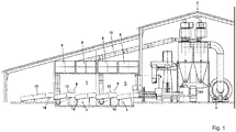
- Fig. 1 shows a schematic view of a drying plant 2 with a drum dryer 4 for drying of drying material 3, in particular of plants that are to be further processed into pellets or bales.
- the drum dryer 4 operates at up to 1000 ° C heated air, wherein for heating the air is a preferably gas-fired furnace is used.
- the drying material 3 is transported at a feeding point 15 onto a chain conveyor 16, which transports the material 3 for drying by means of chains 10 in the direction of the drum dryer 4.
- the drying material 3 is transported by the chain conveyor 16 into a predrying box 5 of a predrying apparatus 1, which in Fig. 2 is shown in a schematic sectional view.
- the chains 10 of the chain conveyor 16 are arranged in an initial region 9 of the predrying box 5 and form an abströmbare surface on which the drying material 3 is arranged.
- By means of a fan 6 air is blown through gaps between chain links of the chains 10 from below into the drying material 3 in order to pre-dry the drying material 3.
- the closed arrows in Fig. 2 symbolize the respective air flow directions 11, the air flow direction 11 in the predrying box 5 extending from the starting area 9 to an end area 7 of the predrying box 5.
- the blown into the pre-drying box 5 air has a second elevated temperature T '', which is usually between 60 ° C and 90 ° C.
- the relative humidity, this injected into the predrying 5 air is typically between 8% and 10%.
- At least one temperature and humidity sensor 20 in the starting region 9 allows the measurement of the temperature and humidity of the air in the initial region 9.
- the air in the end region 7 has a temperature T 0 of about 40 ° C and a relative humidity of 90% to 95%.
- this air is then sucked into a dehumidifier 8, where it is dehumidified and heated to a first elevated temperature T 'between about 40 ° C and about 60 ° C.
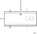
- the structure of the dehumidifier 8 is in Fig. 3 shown schematically, wherein the arrow indicates the air flow direction 11 and the temperature T 0 of the air in front of the dehumidifier and the temperature T 'of the air after the dehumidifier are noted.
- the dehumidifier 8 has an evaporator 17 in which refrigerant (not shown) is vaporized by the heat of the sucked air. As a result, the sucked air is cooled below the dew point, and water condenses on the cold surface of the evaporator 17, from where it runs off or drips.
- the dehumidifier 8 has a condenser 18, in which the refrigerant condenses and thereby releases latent heat.
- the condenser 18 can be used as a heat source for heating the dehumidified air, in which the air, after it has passed the evaporator 17 and has been dehumidified, is also sucked through the condenser 18.
- the dehumidifier 8 comprises a compressor 19 for compressing the refrigerant evaporated in the evaporator 17. Since the compressor 19 in this case gives off heat, the compressor 19 is also suitable as an additional Heat source, which can also be conveniently arranged between the evaporator 17 and condenser 18, without substantially affecting the flow of air from the evaporator 17 to the condenser 18, see Fig. 3 ,
- the temperature of the air can be further heated to a second elevated temperature T "by having a drum heat exchanger 12 downstream of the dehumidifier 8 and upstream of the fan 6, as seen in the air flow direction 11.
- the warmed by the dehumidifier 8 to the temperature T 'air is supplied to the drum heat exchanger via a hopper 24.
- the drum heat exchanger 12, the exhaust gases of the drum dryer 4 are also supplied via an exhaust gas supply line 13 to heat the air from T 'to T''before the exhaust gases are finally discharged through a chimney 14.
- the heat exhaust stream 23 indicated by a curved arrow.
- the air flow rate can be influenced by a control of the fan 6. It should be noted that the density of the drying material 3 may vary, whereby a different resistance for the injected into the predrying 5 air is accompanied. Accordingly, the power or the rotational speed of the fan 6 must be controllable, for which purpose according to the invention frequency converters are provided (not shown). Frequency converters are also preferably used to control the power dehumidifier 8 or the compressor 19 of the dehumidifier 8.
- a sensor or wind speed transmitter 21 is provided for measuring the speed of the sucked air, which is preferably arranged in the dehumidifier 8, behind the evaporator 17. Since the cross-section of the air dehumidifier 8 through which the air can flow is known, the air flow rate results directly from this.
- a pressure sensor 22 is arranged in the starting region 9, preferably also in the end region 7.
- the possible monitoring of the pressure in the starting region 9 or of the resulting differential pressure between the starting region 9 and End region 7 can be used, for example, to ensure that a certain permissible maximum pressure in the starting region 9 or a certain maximum permissible pressure difference is not exceeded. This can occur if the density of the item to be dried 3 is too high and affects the air flow too much. If appropriate, the fan 6 can thus be regulated back accordingly.
- control unit (not shown), which is designed as a programmable logic controller.
- the control unit processes the signals of all sensors 20, 21, 22.
- the execution of the control unit as a programmable logic controller also makes it possible to take into account the current amount of drying material to be dried 3 and set or adjust thresholds for humidity and air flow. Based on this data or information controls and regulates the
- the control unit may control the tumble dryer 12 to set a desired value for the second elevated temperature T ". In this way, the pre-drying is highly automated and optimized.
Landscapes
- Engineering & Computer Science (AREA)
- Mechanical Engineering (AREA)
- General Engineering & Computer Science (AREA)
- Life Sciences & Earth Sciences (AREA)
- Microbiology (AREA)
- Sustainable Development (AREA)
- Drying Of Solid Materials (AREA)
Description
- Die vorliegende Erfindung bezieht sich auf eine Trocknungsanlage zur Trocknung von Trocknungsgut, vorzugsweise von Pflanzen, wobei die Trocknungsanlage eine Vortrocknungsvorrichtung umfasst, die Vortrocknungsvorrichtung umfassend eine Vortrocknungsbox, in welcher das Trocknungsgut anordenbar ist, einen Ventilator, durch den Luft aus einem Endbereich der Vortrocknungsbox ansaugbar und einem Luftentfeuchter zuführbar ist, um mittels des Luftentfeuchters die Luft zu entfeuchten und von einer Temperatur T0 auf eine erste erhöhte Temperatur T' anzuwärmen, wobei mittels des Ventilators die Luft schließlich durch die Vortrocknungsbox von einem Anfangsbereich zum Endbereich blasbar ist, wobei das Trocknungsgut zwischen Anfangsbereich und Endbereich auf einer anströmbare Fläche anordenbar ist.
- Zur Trocknung einer großen Vielzahl an unterschiedlichsten Trocknungsgütern werden Konvektionstrockner eingesetzt, in welchen zum Trocknen des jeweiligen Trocknungsguts mittels eines Gasstroms Wärme in das Trocknungsgut eingetragen und die im Trocknungsgut enthaltene Feuchtigkeit abtransportiert wird. Typische Trocknungsgüter können insbesondere Pflanzen, wie z.B. Gräser, sein, die zu Pellets oder Ballen weiterverarbeitet werden sollen. Es kann sich beim Trocknungsgut aber auch z.B. um organischen Abfall handeln.
- Als Konvektionstrockner kommen typischerweise Trommeltrockner zum Einsatz, deren Trocknungskapazität über einen weiten Bereich dimensioniert werden kann, beispielsweise von 500 bis 50000 Liter Wasserverdunstung pro Stunde. Übliche Gastemperaturen für Konvektionstrockner liegen zwischen 800°C und 1000°C. Zur Erhitzung des Gases kommen dabei in der Regel gasbefeuerte Öfen zum Einsatz.
- Nachteilig an dieser Art des Trocknens ist der hohe Energieeinsatz, insbesondere wenn ein hoher Durchsatz gefordert ist.
- Aus der
US 2011/067262 A1 ist ein Trocknungssystem bekannt, mit welchem Trocknungsgut in einem Behälter getrocknet wird. Dabei wird Trocknungsluft von unten bzw. von einem Boden, auf dem das Trocknungsgut liegt, durch das Trocknungsgut geblasen. Die Trocknungsluft tritt oben aus dem Trocknungsgut aus und wird einem Heizer zugeführt, um weiter aufgeheizt zu werden und mehr Feuchtigkeit aufnehmen zu können. Erst wenn eine gewisse Temperatur und Luftfeuchtigkeit erreicht sind, wird eine Klappe geöffnet, um die Trocknungsluft ab- und einer Entfeuchtungseinrichtung zuzuführen. - Es ist daher Aufgabe der vorliegenden Erfindung, Mittel zur Verfügung zu stellen, die die Trocknung mit geringerem Energieeinsatz bzw. eine energieeffizientere Trocknung im Vergleich zur Trocknung mit bekannten Trocknungsanlagen erlauben.
- Die Erfindung ist eine Trocknungsanlage gemäß Anspruch 1.
- Kern der Erfindung ist es, eine vor dem eigentlichen Trocknungsprozess im Konvektionstrockner eine Vortrocknung in einer vorgeschalteten Vortrocknungsvorrichtung vorzusehen, wobei einerseits ein Luftentfeuchter zum Einsatz kommt, der gleichzeitig zur Entfeuchtung und zum Anwärmen der im Vortrocknungsprozess verwendeten Luft dient, und andererseits die Abgase des Konvektionstrockners zum weiteren Anwärmen dieser Luft ausnutzt, womit eine maximale Energieeffizienz gegeben ist. Dabei erfolgt das weitere Anwärmen in einer Luftströmungsrichtung bzw. Zirkulationsrichtung der Luft nach dem Luftentfeuchter. D.h. die Vortrocknung erfolgt grundsätzlich in einem Umluftbetrieb.
- Es zeigt sich, dass durch das Vortrocknen mit einer Vortrocknungsvorrichtung bereits 20% bis 30% des Wassergehalts aus dem Trocknungsgut entfernt werden können, bevor dieses in den Konvektionstrockner gelangt. Insgesamt ergibt sich dadurch eine entsprechend hohe, in diesem Prozentbereich gelegene Energieeinsparung im Vergleich zur Verwendung des Konvektionstrockners alleine.
- Konkret ist es daher bei einer Trocknungsanlage zur Trocknung von Trocknungsgut, vorzugsweise von Pflanzen, wobei die Trocknungsanlage eine Vortrocknungsvorrichtung umfasst, die Vortrocknungsvorrichtung umfassend eine Vortrocknungsbox, in welcher das Trocknungsgut anordenbar ist, einen Ventilator, durch den Luft aus einem Endbereich der Vortrocknungsbox ansaugbar und einem Luftentfeuchter zuführbar ist, um mittels des Luftentfeuchters die Luft zu entfeuchten und von einer Temperatur T0 auf eine erste erhöhte Temperatur T' anzuwärmen, wobei mittels des Ventilators die Luft schließlich durch die Vortrocknungsbox von einem Anfangsbereich zum Endbereich blasbar ist, wobei das Trocknungsgut zwischen Anfangsbereich und Endbereich auf einer anströmbare Fläche anordenbar ist, erfindungsgemäß vorgesehen, dass die Trocknungsanlage einen Konvektionstrockner umfasst, dem die Vortrocknungsvorrichtung vorgeschaltet ist, und dass in einer Luftströmungsrichtung gesehen nach dem Luftentfeuchter und vor der Vortrocknungsbox ein Wärmetauscher vorgesehen ist, um Luft durch Abgase des Konvektionstrockners auf eine zweite erhöhte Temperatur T" anzuwärmen, wobei T'' ≥ T' gilt.
- Dabei genügen für die Vortrocknung wesentlich geringere Temperaturen als jene, die im Konvektionstrockner zum Einsatz kommen. Konkret ist es bei der erfindungsgemäßen Trocknungsanlage vorgesehen, dass die Vortrocknungsvorrichtung so ausgelegt ist, dass
40°C < T" ≤ 60°C und 60°C ≤ T'' ≤ 90°C gilt. - Um ein besonders effizientes weiters Anwärmen auf die zweite erhöhte Temperatur T'' zu ermöglichen, ist es bei einer bevorzugten Ausführungsform der erfindungsgemäßen Trocknungsanlage vorgesehen, dass es sich bei dem Wärmetauscher um einen Trommelwärmetauscher handelt.
- Bei einer besonders vorteilhaften Ausführungsform der erfindungsgemäßen Trocknungsanlage ist es vorgesehen, dass die anströmbare Fläche durch Ketten eines Kettenförderers gebildet wird. Auf diese Art und Weise kann das Trocknungsgut einfach bei einer Aufgabestelle auf den Kettenförderer aufgegeben werden, und das Trocknungsgut wird mittels des Kettenförderers in Richtung Konvektionstrockner bewegt, während es vorgetrocknet wird, insbesondere in die Vortrocknungsbox hinein und wieder heraus. Dies erleichtert die Integration der erfindungsgemäßen Vortrocknungsvorrichtung in die Trocknungsanlage mit dem Konvektionstrockner. Beispielsweise kann der Transport auf dem Kettenförderer von der Aufgabestelle zum Konvektionstrockner zwischen 1,5 h und 2 h dauern. Durch Lücken der Ketten kann die Luft in das Trocknungsgut strömen, wenn sich dieses in der Vortrocknungsbox befindet.
- Die relative Luftfeuchtigkeit der Luft beträgt typischerweise zwischen 8% und 10%, bevor die Luft in die Vortrocknungsbox eingeblasen wird. In der Vortrocknungsbox nimmt die Luft Feuchtigkeit des Trocknungsguts und verlässt die Vortrocknungsbox mit typischerweise 90% bis 95%. Dabei kühlt die Luft auf eine Temperatur T0 ab, die typischerweise 40°C beträgt.
- Die abgekühlte, feuchte Luft wird nun in den Luftentfeuchter gesaugt. Der Luftentfeuchter weist einen Verdampfer auf, in welchem Kältemittel durch die Wärme der angesaugten Luft verdampft wird, wodurch die angesaugte Luft wiederum unter den Taupunkt abgekühlt wird. Entsprechend kondensiert Wasser auf der kalten Oberfläche des Verdampfers und rinnt bzw. tropft vom Verdampfer ab. Um für eine effiziente Trocknung die entfeuchtete Luft auf die erste erhöhte Temperatur T' anzuwärmen, wird die entfeuchtete Luft durch einen Kondensator des Luftentfeuchters geleitet, in welchem das Kältemittel kondensiert und dabei latente Wärme abgibt, wodurch der Kondensator als Wärmequelle genutzt werden kann.
- Darüber hinaus umfasst der Luftentfeuchter auch einen Kompressor, um das im Verdampfer verdampfte Kältemittel zu komprimieren. Dieser Kompressor kann als zusätzliche Wärmequelle benutzt werden, um die entfeuchtete Luft auf die erste erhöhte Temperatur T' anzuwärmen, obgleich auch andere zusätzliche Wärmequellen, z.B. eine zusätzliche elektrische Heizung vorstellbar wären.
- Der Kompressor eignet sich deshalb besonders gut als zusätzliche Wärmequelle, da der Kompressor Wärme abgibt und zudem bequem zwischen Verdampfer und Kondensator untergebracht werden kann, ohne die Strömung der Luft vom Verdampfer zum Kondensator wesentlich zu beeinträchtigen. Dies trägt erheblich zur Ausnutzung möglichst aller ohnehin vorhandenen Wärmequellen für das Anwärmen der Luft bei - und damit zur Optimierung der Energieeffizienz der erfindungsgemäßen Vortrocknungsvorrichtung. Daher ist es bei der erfindungsgemäßen Trocknungsanlage vorgesehen, dass der Luftentfeuchter einen Verdampfer und
einen Kondensator aufweist, wobei der Verdampfer und der Kondensator derart angeordnet sind, dass die dem Luftentfeuchter zugeführte Luft sowohl durch den Verdampfer als auch durch den Kondensator führbar ist, wobei weiters zwischen Verdampfer und Kondensator eine Wärmequelle angeordnet ist, um die durch den Verdampfer durchgetretene Luft zusätzlich anzuwärmen, und wobei der Luftentfeuchter einen Kompressor umfasst, der zumindest teilweise, vorzugsweise vollständig die Wärmequelle ausbildet. - Um den Vortrocknungsvorgang steuern zu können, ist es wünschenswert, den Luftdurchsatz durch die Vortrocknungsbox einstellen zu können. Dies kann grundsätzlich durch eine Steuerung des Ventilators erfolgen. Hierbei ist zu berücksichtigen, dass die Dichte an aufgebebenem Trocknungsgut variieren kann, womit ein unterschiedlicher Widerstand für die in die Vortrocknungsbox eingeblasene Luft einhergeht. Daher ist es bei einer bevorzugten Ausführungsform der erfindungsgemäßen Trocknungsanlage vorgesehen, dass der Ventilator eine Drehzahlsteuerung aufweist, um die angesaugte Luftmenge auf einen vorgegebenen Wert einzustellen.
- Eine einfach zu realisierende Möglichkeit zur Steuerung der Drehzahl des Ventilators aber auch zur Leistung des Luftentfeuchters, wobei diese im Wesentlichen durch die Leistung des Kompressors bestimmt wird, bieten Frequenzumrichter. Daher ist es bei einer bevorzugten Ausführungsform der erfindungsgemäßen Trocknungsanlage vorgesehen, dass zur Steuerung des Ventilators und/oder des Luftentfeuchters Frequenzumrichter vorgesehen sind.
- Um die Menge an angesaugter Luft messen zu können, ist es bei einer bevorzugten Ausführungsform der erfindungsgemäßen Trocknungsanlage vorgesehen, dass ein Sensor zur Messung der Geschwindigkeit der angesaugten Luft vorgesehen ist, der vorzugsweise im Luftentfeuchter hinter dem Verdampfer angeordnet ist. Das Messergebnis kann in der Folge als Regelgröße zur Steuerung des mindestens einen Ventilators verwendet werden. Die Anordnung des Sensors hinter dem Verdampfer hat den Vorteil, dass der Verdampfer einen gewissen Schutz für den Sensor vor Staub bietet. Zudem erweist sich diese Sensoranordnung als besonders günstig, da der Luftentfeuchter eine definierte Querschnittsfläche darstellt, durch die die angesaugte Luftmenge durchtreten muss. Da diese Querschnittsfläche bekannt ist, kann durch Messung der Luftgeschwindigkeit im Luftentfeuchter unmittelbar auf die Menge der angesaugten Luft pro Zeit geschlossen werden.
- Weiters ist es bei einer besonders bevorzugten Ausführungsform der erfindungsgemäßen Trocknungsanlage vorgesehen, dass im Anfangsbereich ein Sensor zur Messung des Drucks der eingeblasenen Luft angeordnet ist. Die damit mögliche Überwachung des Drucks im Anfangsbereich bzw. des sich ergebenden Differenzdrucks zwischen Anfangsbereich und Endbereich kann beispielsweise dazu verwendet werden sicherzustellen, dass ein gewisser zulässiger Höchstdruck im Anfangsbereich bzw. eine gewisse höchstzulässige Druckdifferenz nicht überschritten wird. Dies kann dann auftreten, wenn die Dichte des Trocknungsguts zu hoch ist und den Luftdurchsatz zu stark beeinträchtigt. Gegebenenfalls kann somit der mindestens eine Ventilator entsprechend zurückgeregelt werden.
- Um den Trocknungsvorgang zu überwachen und automatisieren zu können, ist es bei einer bevorzugten Ausführungsform der erfindungsgemäßen Trocknungsanlage vorgesehen, dass sowohl im Anfangsbereich als auch im Endbereich Sensoren zur Messung der Temperatur und der Luftfeuchtigkeit vorgesehen sind.
- Um für eine Automatisierung des Trocknungsvorgangs die Signale sämtlicher Sensoren verarbeiten zu können, ist es bei einer bevorzugten Ausführungsform der erfindungsgemäßen Trocknungsanlage vorgesehen, dass eine Regel-Steuereinheit, die vorzugsweise als speicherprogrammierbare Steuerung ausgeführt ist, vorgesehen ist, mittels welcher der Ventilator, der Luftentfeuchter sowie der Wärmetauscher ansteuerbar und/oder regelbar sind. Die Ausführung als speicherprogrammierbare Steuerung ermöglicht es beispielsweise, die Menge an aktuell zu trocknenden Trocknungsgut zu berücksichtigen und Schwellwerte für Luftfeuchtigkeit und Luftdurchsatz vorzugeben bzw. anzupassen.
- Wie bereits festgehalten, lässt sich die Vortrocknungsvorrichtung problemlos in die erfindungsgemäße Trocknungsanlage integrieren.
- Schließlich können insbesondere zur Bewältigung großer Mengen an Trocknungsgut bzw. zur Durchsatzsteigerung auch mehrere Vortrocknungsvorrichtungen hintereinander geschaltet sein. Entsprechend ist es bei einer bevorzugten Ausführungsform der erfindungsgemäßen Trocknungsanlage vorgesehen, dass mehrere Vortrocknungsvorrichtungen vorgesehen sind, die nacheinander angeordnet sind.
- Die Erfindung wird nun anhand eines(von) Ausführungsbeispiels(en) näher erläutert. Die Zeichnungen sind beispielhaft und sollen den Erfindungsgedanken zwar darlegen, ihn aber keinesfalls einengen oder gar abschließend wiedergeben.
- Dabei zeigt:
- Fig. 1
- eine schematische Ansicht einer erfindungsgemäßen Trocknungsanlage mit Vortrocknungsvorrichtungen
- Fig. 2
- eine schematische Schnittansicht einer Vortrocknungsvorrichtung
- Fig. 3
- eine schematische Darstellung eines Luftentfeuchters einer Vortrocknungsvorrichtung
-
Fig. 1 zeigt eine schematische Ansicht einer Trocknungsanlage 2 mit einem Trommeltrockner 4 zur Trocknung von Trocknungsgut 3, insbesondere von Pflanzen, die zu Pellets oder Ballen weiterverarbeitet werden sollen. Der Trommeltrockner 4 arbeitet mit auf bis zu 1000°C erhitzter Luft, wobei zum Aufheizen der Luft ein, vorzugsweise mit Gas befeuerter Ofen verwendet wird. Das Trocknungsgut 3 wird bei einer Aufgabestelle 15 auf einen Kettenförderer 16, der das Trocknungsgut 3 mittels Ketten 10 in Richtung Trommeltrockner 4 transportiert. - Um das Trocknungsgut 3 vorzutrocknen, wird das Trocknungsgut 3 durch den Kettenförderer 16 in eine Vortrocknungsbox 5 einer Vortrocknungsvorrichtung 1 transportiert, welche in
Fig. 2 in einer schematischen Schnittansicht dargestellt ist. Die Ketten 10 des Kettenförderers 16 sind in einem Anfangsbereich 9 der Vortrocknungsbox 5 angeordnet und bilden eine anströmbare Fläche, auf der das Trocknungsgut 3 angeordnet ist. Mittels eines Ventilators 6 wird Luft durch Lücken zwischen Kettengliedern der Ketten 10 von unten in das Trocknungsgut 3 eingeblasen, um das Trocknungsgut 3 vorzutrocknen. Die geschlossenen Pfeile inFig. 2 symbolisieren die jeweiligen Luftströmungsrichtungen 11, wobei die Luftströmungsrichtung 11 in der Vortrocknungsbox 5 vom Anfangsbereich 9 zu einem Endbereich 7 der Vortrocknungsbox 5 verläuft. - Die in die Vortrocknungsbox 5 eingeblasene Luft weist eine zweite erhöhte Temperatur T'' auf, die üblicherweise zwischen 60°C und 90°C liegt. Die relative Luftfeuchtigkeit, dieser in die Vortrocknungsbox 5 eingeblasenen Luft beträgt dabei typischerweise zwischen 8% und 10%. Mindestens ein Temperatur- und Feuchtigkeitssensor 20 im Anfangsbereich 9 gestattet die Messung von Temperatur und Luftfeuchtigkeit der Luft im Anfangsbereich 9.
- Beim Durchtritt der Luft durch das Trocknungsgut 3 kühlt die Luft ab und nimmt Feuchtigkeit des Trocknungsguts 3 auf. Typischerweise weist die Luft im Endbereich 7 eine Temperatur T0 von ca. 40°C und eine relative Luftfeuchtigkeit von 90% bis 95% auf.
- Mittels des Ventilators 6 wird diese Luft nun in einen Luftentfeuchter 8 gesaugt, wo sie entfeuchtet und auf eine erste erhöhte Temperatur T' zwischen ca. 40°C und ca. 60°C angewärmt wird.
- Der Aufbau des Luftentfeuchters 8 ist in
Fig. 3 schematisch gezeigt, wobei der Pfeil die Luftströmungsrichtung 11 anzeigt und die Temperatur T0 der Luft vor dem Luftentfeuchter sowie die Temperatur T' der Luft nach dem Luftentfeuchter vermerkt sind. Der Luftentfeuchter 8 weist einen Verdampfer 17 auf, in welchem Kältemittel (nicht dargestellt) durch die Wärme der angesaugten Luft verdampft wird. Hierdurch wird die angesaugte Luft unter den Taupunkt abgekühlt, und Wasser kondensiert auf der kalten Oberfläche des Verdampfers 17, von wo es abrinnt bzw. abtropft. Weiters weist der Luftentfeuchter 8 einen Kondensator 18 auf, in welchem das Kältemittel kondensiert und dabei latente Wärme abgibt. Hierdurch kann der Kondensator 18 als Wärmequelle zum Anwärmen der entfeuchteten Luft genutzt werden, in dem die Luft, nachdem sie den Verdampfer 17 passiert hat und entfeuchtet worden ist, auch durch den Kondensator 18 gesaugt wird. - Darüberhinaus umfasst der Luftentfeuchter 8 einen Kompressor 19, um das im Verdampfer 17 verdampfte Kältemittel zu komprimieren. Da der Kompressor 19 hierbei Wärme abgibt, eignet sich auch der Kompressor 19 als zusätzliche Wärmequelle, die zudem bequem zwischen Verdampfer 17 und Kondensator 18 angeordnet werden kann, ohne die Strömung der Luft vom Verdampfer 17 zum Kondensator 18 wesentlich zu beeinträchtigen, siehe
Fig. 3 . - Durch Nutzung des Kondensators 18 sowie des Kompressors 19 als - ohnehin vorhandene - Wärmequellen erfolgt die Anhebung der Temperatur der Luft von T0 auf die erste erhöhte Temperatur T' gänzlich ohne weitere Wärmequellen. Im Prinzip wäre es möglich, bereits mit Luft, die lediglich auf T' - und nicht auf T'' - erwärmt ist, brauchbare Vortrocknungsergebnisse zu erzielen.
- Allerdings kann im vorliegenden Fall zur Steigerung der Vortrocknungsleistung die Temperatur der Luft weiter, auf eine zweite erhöhte Temperatur T'' erwärmt werden, indem in Luftströmungsrichtung 11 gesehen nach dem Luftentfeuchter 8 und vor dem Ventilator 6 ein Trommelwärmetauscher 12 vorgesehen ist. Die durch den Luftentfeuchter 8 auf die Temperatur T' angewärmte Luft wird dem Trommelwärmetauscher über einen Trichter 24 zugeführt. Dem Trommelwärmetauscher 12 werden außerdem die Abgase des Trommeltrockners 4 über eine Abgaszuleitung 13 zugeführt, um die Luft von T' auf T'' anzuwärmen, bevor die Abgase schließlich über einen Kamin 14 abgeführt werden. Zur Verdeutlichung ist in
Fig. 2 der Wärmeabgasstrom 23 mit einem gekrümmten Pfeil angedeutet. - Ein weiterer zu beachtender Punkt bei der Steuerung des Trocknungsvorgangs ist der Luftdurchsatz. Der Luftdurchsatz kann durch eine Steuerung des Ventilators 6 beeinflusst werden. Hierbei ist zu berücksichtigen, dass die Dichte des Trocknungsguts 3 variieren kann, womit ein unterschiedlicher Widerstand für die in die Vortrocknungsbox 5 eingeblasene Luft einhergeht. Entsprechend muss die Leistung bzw. die Drehzahl des Ventilators 6 steuerbar sein, wobei hierfür erfindungsgemäß Frequenzumrichter vorgesehen sind (nicht dargestellt). Vorzugsweise werden Frequenzumrichter außerdem auch zur Steuerung der Leistung Luftentfeuchters 8 bzw. des Kompressors 19 des Luftentfeuchters 8 eingesetzt.
- Zur Bestimmung des Luftdurchsatzes bzw. der angesaugten Luftmenge ist ein Sensor bzw. Windgeschwindigkeitsmessumformer 21 zur Messung der Geschwindigkeit der angesaugten Luft vorgesehen, der vorzugsweise im Luftentfeuchter 8, hinter dem Verdampfer 17 angeordnet ist. Da der von der Luft durchströmbare Querschnitt des Luftentfeuchters 8 bekannt ist, ergibt sich daraus unmittelbar der Luftdurchsatz.
- Weiters ist zur Überwachung des Drucks der Luft, die in die Vortrocknungsbox 5 eingeblasen wird, im Anfangsbereich 9 ein Drucksensor 22 angeordnet, vorzugsweise ebenso im Endbereich 7. Die damit mögliche Überwachung des Drucks im Anfangsbereich 9 bzw. des sich ergebenden Differenzdrucks zwischen Anfangsbereich 9 und Endbereich 7 kann beispielsweise dazu verwendet werden sicherzustellen, dass ein gewisser zulässiger Höchstdruck im Anfangsbereich 9 bzw. eine gewisse höchstzulässige Druckdifferenz nicht überschritten wird. Dies kann dann auftreten, wenn die Dichte des Trocknungsguts 3 zu hoch ist und den Luftdurchsatz zu stark beeinträchtigt. Gegebenenfalls kann somit der Ventilator 6 entsprechend zurückgeregelt werden.
- Sämtliche Regel- und Steuervorgänge werden im gezeigten Ausführungsbeispiel durch eine Regel-Steuereinheit (nicht dargestellt) kontrolliert, die als speicherprogrammierbare Steuerung ausgeführt ist. Die Regel-Steuereinheit verarbeitet die Signale sämtlicher Sensoren 20, 21, 22. Die Ausführung der Regel-Steuereinheit als speicherprogrammierbare Steuerung ermöglicht es zudem, die aktuelle Menge des zu trocknenden Trocknungsguts 3 zu berücksichtigen und Schwellwerte für Luftfeuchtigkeit und Luftdurchsatz vorzugeben bzw. anzupassen. Basierend auf diesen Daten bzw. Angaben steuert und regelt die Regel-Steuereinheit die Leistung des Ventilators 6 sowie des Luftentfeuchters 8. Zudem kann die Regel-Steuereinheit den Trommeltrockner 12 ansteuern, um einen gewünschten Wert für die zweite erhöhte Temperatur T'' einzustellen. Auf diese Weise wird die Vortrocknung hochgradig automatisiert und optimiert durchgeführt.
-
- 1
- Vortrocknungsvorrichtung
- 2
- Trocknungsanlage
- 3
- Trocknungsgut
- 4
- Trommeltrockner
- 5
- Vortrocknungsbox
- 6
- Ventilator
- 7
- Endbereich der Vortrocknungsbox
- 8
- Luftentfeuchter
- 9
- Anfangsbereich der Vortrocknungsbox
- 10
- Kette eines Kettenförderers
- 11
- Luftströmungsrichtung
- 12
- Trommelwärmetauscher
- 13
- Abgaszuleitung
- 14
- Kamin
- 15
- Aufgabestelle
- 16
- Kettenförderer
- 17
- Verdampfer
- 18
- Kondensator
- 19
- Kompressor
- 20
- Temperatur- und Feuchtigkeitssensor
- 21
- Windgeschwindigkeitsmessumformer
- 22
- Drucksensor
- 23
- Wärmeabgasstrom
- 24
- Trichter
Claims (10)
- Trocknungsanlage (2) zur Trocknung von Trocknungsgut (3), vorzugsweise von Pflanzen, wobei die Trocknungsanlage (2) eine Vortrocknungsvorrichtung (1) umfasst, die Vortrocknungsvorrichtung (1) umfassend eine Vortrocknungsbox (5), in welcher das Trocknungsgut (3) anordenbar ist, einen Ventilator (6), durch den Luft aus einem Endbereich (7) der Vortrocknungsbox (5) ansaugbar und einem Luftentfeuchter (8) zuführbar ist, um mittels des Luftentfeuchters (8) die Luft zu entfeuchten und von einer Temperatur T0 auf eine erste erhöhte Temperatur T' anzuwärmen,
wobei mittels des Ventilators (6) die Luft schließlich durch die Vortrocknungsbox (5) von einem Anfangsbereich (9) zum Endbereich (7) blasbar ist, wobei das Trocknungsgut (3) zwischen Anfangsbereich (9) und Endbereich (7) auf einer anströmbare Fläche (10) anordenbar ist, dadurch gekennzeichnet, dass die Trocknungsanlage (2) einen Konvektionstrockner (4) umfasst, dem die Vortrocknungsvorrichtung (1) vorgeschaltet ist, dass in einer Luftströmungsrichtung (11) gesehen nach dem Luftentfeuchter (8) und vor der Vortrocknungsbox (5) ein Wärmetauscher (12) vorgesehen ist, um Luft durch Abgase des Konvektionstrockners (4) auf eine zweite erhöhte Temperatur T'' anzuwärmen, wobei T'' ≥ T' gilt, dass der Luftentfeuchter (8) einen Verdampfer (17) und einen Kondensator (18) aufweist, wobei der Verdampfer (17) und der Kondensator (18) derart angeordnet sind, dass die dem Luftentfeuchter (8) zugeführte Luft sowohl durch den Verdampfer (17) als auch durch den Kondensator (18) führbar ist, wobei weiters zwischen Verdampfer (17) und Kondensator (18) eine Wärmequelle angeordnet ist, um die durch den Verdampfer (17) durchgetretene Luft zusätzlich anzuwärmen, und wobei der Luftentfeuchter (8) einen Kompressor (19) umfasst, der zumindest teilweise, vorzugsweise vollständig die Wärmequelle ausbildet, und dass die Vortrocknungsvorrichtung (1) so ausgelegt ist, dass 40°C < T'' ≤ 60°C und 60°C ≤ T'' ≤ 90°C gilt. - Trocknungsanlage (2) nach Anspruch 1, dadurch gekennzeichnet, dass es sich bei dem Wärmetauscher um einen Trommelwärmetauscher (12) handelt.
- Trocknungsanlage (2) nach einem der Ansprüche 1 bis 2, dadurch gekennzeichnet, dass die anströmbare Fläche durch Ketten (10) eines Kettenförderers (16) gebildet wird.
- Trocknungsanlage (2) nach einem der Ansprüche 1 bis 3, dadurch gekennzeichnet, dass der Ventilator (6) eine Drehzahlsteuerung aufweist, um die angesaugte Luftmenge auf einen vorgegebenen Wert einzustellen.
- Trocknungsanlage (2) nach einem der Ansprüche 1 bis 4, dadurch gekennzeichnet, dass zur Steuerung des Ventilators (6) und/oder des Luftentfeuchters (8) Frequenzumrichter vorgesehen sind.
- Trocknungsanlage (2) nach einem der Ansprüche 1 bis 5, dadurch gekennzeichnet, dass sowohl im Anfangsbereich (9) als auch im Endbereich (7) Sensoren (20) zur Messung der Temperatur und der Feuchtigkeit der Luft vorgesehen sind.
- Trocknungsanlage (2) nach einem der Ansprüche 1 bis 6, dadurch gekennzeichnet, dass ein Sensor (21) zur Messung der Geschwindigkeit der angesaugten Luft vorgesehen ist, der vorzugsweise im Luftentfeuchter (8) hinter dem Verdampfer (17) angeordnet ist.
- Trocknungsanlage (2) nach einem der Ansprüche 1 bis 7, dadurch gekennzeichnet, dass im Anfangsbereich (9) ein Sensor (22) zur Messung des Drucks der eingeblasenen Luft angeordnet ist.
- Trocknungsanlage (2) nach einem der Ansprüche 1 bis 8, dadurch gekennzeichnet, dass eine Regel-Steuereinheit, die vorzugsweise als speicherprogrammierbare Steuerung ausgeführt ist, vorgesehen ist, mittels welcher der Ventilator (6), der Luftentfeuchter (8) sowie der Wärmetauscher (12) ansteuerbar und/oder regelbar sind.
- Trocknungsanlage (2) nach einem der Ansprüche 1 bis 9, dadurch gekennzeichnet, dass mehrere Vortrocknungsvorrichtungen (1) vorgesehen sind, die nacheinander angeordnet sind.
Applications Claiming Priority (1)
| Application Number | Priority Date | Filing Date | Title |
|---|---|---|---|
| ATGM50136/2014U AT14386U1 (de) | 2014-08-29 | 2014-08-29 | Vortrocknungsvorrichtung für eine trocknungsanlage |
Publications (2)
| Publication Number | Publication Date |
|---|---|
| EP2993433A1 EP2993433A1 (de) | 2016-03-09 |
| EP2993433B1 true EP2993433B1 (de) | 2019-06-26 |
Family
ID=54253374
Family Applications (1)
| Application Number | Title | Priority Date | Filing Date |
|---|---|---|---|
| EP15178561.5A Not-in-force EP2993433B1 (de) | 2014-08-29 | 2015-07-28 | Vortrocknungsvorrichtung für eine trocknungsanlage |
Country Status (2)
| Country | Link |
|---|---|
| EP (1) | EP2993433B1 (de) |
| AT (1) | AT14386U1 (de) |
Families Citing this family (4)
| Publication number | Priority date | Publication date | Assignee | Title |
|---|---|---|---|---|
| SE539634C2 (en) * | 2015-05-11 | 2017-10-24 | Coldbay Ab | Method for determining an action requiring state in a compartment for drying wood |
| CA3002202A1 (en) | 2017-04-25 | 2018-10-25 | Emil J. Gulbranson | Hay bale dryer |
| CN115523743B (zh) * | 2022-08-09 | 2023-12-15 | 青岛海尔空调器有限总公司 | 热泵烘干机及其控制方法 |
| CN115654905B (zh) * | 2022-11-22 | 2023-08-04 | 江苏泰利达新材料股份有限公司 | 一种用于羧甲基纤维素钠生产的烘干装置 |
Family Cites Families (9)
| Publication number | Priority date | Publication date | Assignee | Title |
|---|---|---|---|---|
| US2137347A (en) * | 1932-10-17 | 1938-11-22 | Olsson Johan Gustaf | Method of drying various materials and means for carrying out such method |
| CH216480A (de) * | 1940-09-14 | 1941-08-31 | Bbc Brown Boveri & Cie | Trockner mit Wärmerückgewinnung. |
| SE429785B (sv) * | 1978-10-13 | 1983-09-26 | Svenska Traeforskningsinst | Forfarande for torkning med varmluft |
| FR2535445B1 (fr) * | 1982-10-28 | 1987-10-16 | Conditionair Sa | Installation de sechage |
| US4642904A (en) * | 1985-08-01 | 1987-02-17 | Georgia Krolin Company, Inc. | Energy conserving process for drying a clay slurry |
| DE19734319A1 (de) * | 1997-08-08 | 1999-02-11 | Krc Umwelttechnik Gmbh | Verfahren und Anlage zur Behandlung von feuchten Reststoffen |
| AT503896B1 (de) * | 2006-06-21 | 2008-10-15 | Andritz Tech & Asset Man Gmbh | Verfahren und anlage zur verarbeitung von feuchtgut |
| SE532586C2 (sv) * | 2008-06-04 | 2010-02-23 | Eero Erma | Torksystem med cirkulerande gas |
| FR2954814B1 (fr) * | 2009-12-30 | 2012-03-02 | Degremont | Procede et installation de sechage de matieres pateuses, en particulier de boues de stations d'epuration, avec generation d'energie thermique. |
-
2014
- 2014-08-29 AT ATGM50136/2014U patent/AT14386U1/de not_active IP Right Cessation
-
2015
- 2015-07-28 EP EP15178561.5A patent/EP2993433B1/de not_active Not-in-force
Non-Patent Citations (1)
| Title |
|---|
| None * |
Also Published As
| Publication number | Publication date |
|---|---|
| EP2993433A1 (de) | 2016-03-09 |
| AT14386U1 (de) | 2015-10-15 |
Similar Documents
| Publication | Publication Date | Title |
|---|---|---|
| EP3187807B1 (de) | Vorrichtung zum trocknen von heu | |
| EP2993433B1 (de) | Vortrocknungsvorrichtung für eine trocknungsanlage | |
| EP2876396B1 (de) | Verfahren zum Trocknen von Trocknungsgut | |
| WO2008122265A1 (de) | Vorrichtung und verfahren zum entwässern und trocknen eines gemisches aus kunststoffgranulat und wasser | |
| EP2326900B1 (de) | Verfahren und vorrichtung zum trocknen von biomasse | |
| DE102009001024A1 (de) | Verfahren und Anlage zum Trocknen von Feuchtgut | |
| EP3048296A1 (de) | Verfahren zum enteisen eines rotorblatts einer windenergieanlage | |
| DE102016014643A1 (de) | Durchlauftrockner zum Trocknen eines Gutes mittels Warmluft mit mindestens zwei Sektionen | |
| EP3411646A1 (de) | Durchlauftrockner mit mindestens zwei sektionen | |
| DE102009007789B3 (de) | Trocknungsanlage für landwirtschaftliche Körnerfrüchte | |
| DE102016101725A1 (de) | Durchlauftrockner mit mindestens zwei Sektionen | |
| DE102015209370B3 (de) | Trockner | |
| DE2546494C3 (de) | Verfahren zur Langzeitkonservierung von Getreide | |
| DE10221254B4 (de) | Verfahren und Vorrichtung zum Entfeuchten von Lebensmitteln | |
| DE102019114467A1 (de) | Verfahren zur Entschwadung von Prozessabluft | |
| DE10233015A1 (de) | Vorrichtung und Verfahren zur Trocknung eines Gasstromes | |
| AT514695B1 (de) | Vorrichtung und Verfahren zum Trocknen von Trocknungsgut | |
| EP2372264B1 (de) | Verfahren zum Betreiben eines lufttechnischen Geräts, lufttechnisches Gerät und Raum mit lufttechnischem Gerät | |
| DE19507284C2 (de) | Vorrichtung zum Verhindern von Kondenswasserbildung | |
| DE102016103685C5 (de) | Durchlauftrockner mit mindestens zwei Sektionen | |
| DE102007045318B4 (de) | Verfahren zum Konditionieren von Hopfen | |
| DE3914220C2 (de) | ||
| WO2019048411A1 (de) | Konditionieren von tabak | |
| EP1987303B1 (de) | Wirbelschichttrockner | |
| DE102004045255B4 (de) | Humidor |
Legal Events
| Date | Code | Title | Description |
|---|---|---|---|
| PUAI | Public reference made under article 153(3) epc to a published international application that has entered the european phase |
Free format text: ORIGINAL CODE: 0009012 |
|
| AK | Designated contracting states |
Kind code of ref document: A1 Designated state(s): AL AT BE BG CH CY CZ DE DK EE ES FI FR GB GR HR HU IE IS IT LI LT LU LV MC MK MT NL NO PL PT RO RS SE SI SK SM TR |
|
| AX | Request for extension of the european patent |
Extension state: BA ME |
|
| 17P | Request for examination filed |
Effective date: 20160908 |
|
| RBV | Designated contracting states (corrected) |
Designated state(s): AL AT BE BG CH CY CZ DE DK EE ES FI FR GB GR HR HU IE IS IT LI LT LU LV MC MK MT NL NO PL PT RO RS SE SI SK SM TR |
|
| STAA | Information on the status of an ep patent application or granted ep patent |
Free format text: STATUS: EXAMINATION IS IN PROGRESS |
|
| 17Q | First examination report despatched |
Effective date: 20180116 |
|
| GRAP | Despatch of communication of intention to grant a patent |
Free format text: ORIGINAL CODE: EPIDOSNIGR1 |
|
| STAA | Information on the status of an ep patent application or granted ep patent |
Free format text: STATUS: GRANT OF PATENT IS INTENDED |
|
| INTG | Intention to grant announced |
Effective date: 20180907 |
|
| GRAJ | Information related to disapproval of communication of intention to grant by the applicant or resumption of examination proceedings by the epo deleted |
Free format text: ORIGINAL CODE: EPIDOSDIGR1 |
|
| STAA | Information on the status of an ep patent application or granted ep patent |
Free format text: STATUS: EXAMINATION IS IN PROGRESS |
|
| GRAP | Despatch of communication of intention to grant a patent |
Free format text: ORIGINAL CODE: EPIDOSNIGR1 |
|
| STAA | Information on the status of an ep patent application or granted ep patent |
Free format text: STATUS: GRANT OF PATENT IS INTENDED |
|
| INTC | Intention to grant announced (deleted) | ||
| INTG | Intention to grant announced |
Effective date: 20190123 |
|
| GRAS | Grant fee paid |
Free format text: ORIGINAL CODE: EPIDOSNIGR3 |
|
| GRAA | (expected) grant |
Free format text: ORIGINAL CODE: 0009210 |
|
| STAA | Information on the status of an ep patent application or granted ep patent |
Free format text: STATUS: THE PATENT HAS BEEN GRANTED |
|
| AK | Designated contracting states |
Kind code of ref document: B1 Designated state(s): AL AT BE BG CH CY CZ DE DK EE ES FI FR GB GR HR HU IE IS IT LI LT LU LV MC MK MT NL NO PL PT RO RS SE SI SK SM TR |
|
| REG | Reference to a national code |
Ref country code: GB Ref legal event code: FG4D Free format text: NOT ENGLISH |
|
| REG | Reference to a national code |
Ref country code: CH Ref legal event code: EP |
|
| REG | Reference to a national code |
Ref country code: AT Ref legal event code: REF Ref document number: 1148779 Country of ref document: AT Kind code of ref document: T Effective date: 20190715 |
|
| REG | Reference to a national code |
Ref country code: IE Ref legal event code: FG4D Free format text: LANGUAGE OF EP DOCUMENT: GERMAN |
|
| REG | Reference to a national code |
Ref country code: DE Ref legal event code: R096 Ref document number: 502015009423 Country of ref document: DE |
|
| REG | Reference to a national code |
Ref country code: NL Ref legal event code: MP Effective date: 20190626 |
|
| PG25 | Lapsed in a contracting state [announced via postgrant information from national office to epo] |
Ref country code: NO Free format text: LAPSE BECAUSE OF FAILURE TO SUBMIT A TRANSLATION OF THE DESCRIPTION OR TO PAY THE FEE WITHIN THE PRESCRIBED TIME-LIMIT Effective date: 20190926 Ref country code: HR Free format text: LAPSE BECAUSE OF FAILURE TO SUBMIT A TRANSLATION OF THE DESCRIPTION OR TO PAY THE FEE WITHIN THE PRESCRIBED TIME-LIMIT Effective date: 20190626 Ref country code: SE Free format text: LAPSE BECAUSE OF FAILURE TO SUBMIT A TRANSLATION OF THE DESCRIPTION OR TO PAY THE FEE WITHIN THE PRESCRIBED TIME-LIMIT Effective date: 20190626 Ref country code: FI Free format text: LAPSE BECAUSE OF FAILURE TO SUBMIT A TRANSLATION OF THE DESCRIPTION OR TO PAY THE FEE WITHIN THE PRESCRIBED TIME-LIMIT Effective date: 20190626 Ref country code: AL Free format text: LAPSE BECAUSE OF FAILURE TO SUBMIT A TRANSLATION OF THE DESCRIPTION OR TO PAY THE FEE WITHIN THE PRESCRIBED TIME-LIMIT Effective date: 20190626 Ref country code: LT Free format text: LAPSE BECAUSE OF FAILURE TO SUBMIT A TRANSLATION OF THE DESCRIPTION OR TO PAY THE FEE WITHIN THE PRESCRIBED TIME-LIMIT Effective date: 20190626 |
|
| PGFP | Annual fee paid to national office [announced via postgrant information from national office to epo] |
Ref country code: FR Payment date: 20190725 Year of fee payment: 5 Ref country code: DE Payment date: 20190828 Year of fee payment: 5 |
|
| REG | Reference to a national code |
Ref country code: LT Ref legal event code: MG4D |
|
| PG25 | Lapsed in a contracting state [announced via postgrant information from national office to epo] |
Ref country code: BG Free format text: LAPSE BECAUSE OF FAILURE TO SUBMIT A TRANSLATION OF THE DESCRIPTION OR TO PAY THE FEE WITHIN THE PRESCRIBED TIME-LIMIT Effective date: 20190926 Ref country code: LV Free format text: LAPSE BECAUSE OF FAILURE TO SUBMIT A TRANSLATION OF THE DESCRIPTION OR TO PAY THE FEE WITHIN THE PRESCRIBED TIME-LIMIT Effective date: 20190626 Ref country code: RS Free format text: LAPSE BECAUSE OF FAILURE TO SUBMIT A TRANSLATION OF THE DESCRIPTION OR TO PAY THE FEE WITHIN THE PRESCRIBED TIME-LIMIT Effective date: 20190626 Ref country code: GR Free format text: LAPSE BECAUSE OF FAILURE TO SUBMIT A TRANSLATION OF THE DESCRIPTION OR TO PAY THE FEE WITHIN THE PRESCRIBED TIME-LIMIT Effective date: 20190927 |
|
| PG25 | Lapsed in a contracting state [announced via postgrant information from national office to epo] |
Ref country code: SK Free format text: LAPSE BECAUSE OF FAILURE TO SUBMIT A TRANSLATION OF THE DESCRIPTION OR TO PAY THE FEE WITHIN THE PRESCRIBED TIME-LIMIT Effective date: 20190626 Ref country code: RO Free format text: LAPSE BECAUSE OF FAILURE TO SUBMIT A TRANSLATION OF THE DESCRIPTION OR TO PAY THE FEE WITHIN THE PRESCRIBED TIME-LIMIT Effective date: 20190626 Ref country code: EE Free format text: LAPSE BECAUSE OF FAILURE TO SUBMIT A TRANSLATION OF THE DESCRIPTION OR TO PAY THE FEE WITHIN THE PRESCRIBED TIME-LIMIT Effective date: 20190626 Ref country code: PT Free format text: LAPSE BECAUSE OF FAILURE TO SUBMIT A TRANSLATION OF THE DESCRIPTION OR TO PAY THE FEE WITHIN THE PRESCRIBED TIME-LIMIT Effective date: 20191028 Ref country code: CZ Free format text: LAPSE BECAUSE OF FAILURE TO SUBMIT A TRANSLATION OF THE DESCRIPTION OR TO PAY THE FEE WITHIN THE PRESCRIBED TIME-LIMIT Effective date: 20190626 Ref country code: NL Free format text: LAPSE BECAUSE OF FAILURE TO SUBMIT A TRANSLATION OF THE DESCRIPTION OR TO PAY THE FEE WITHIN THE PRESCRIBED TIME-LIMIT Effective date: 20190626 |
|
| PG25 | Lapsed in a contracting state [announced via postgrant information from national office to epo] |
Ref country code: IS Free format text: LAPSE BECAUSE OF FAILURE TO SUBMIT A TRANSLATION OF THE DESCRIPTION OR TO PAY THE FEE WITHIN THE PRESCRIBED TIME-LIMIT Effective date: 20191026 Ref country code: SM Free format text: LAPSE BECAUSE OF FAILURE TO SUBMIT A TRANSLATION OF THE DESCRIPTION OR TO PAY THE FEE WITHIN THE PRESCRIBED TIME-LIMIT Effective date: 20190626 Ref country code: IT Free format text: LAPSE BECAUSE OF FAILURE TO SUBMIT A TRANSLATION OF THE DESCRIPTION OR TO PAY THE FEE WITHIN THE PRESCRIBED TIME-LIMIT Effective date: 20190626 Ref country code: ES Free format text: LAPSE BECAUSE OF FAILURE TO SUBMIT A TRANSLATION OF THE DESCRIPTION OR TO PAY THE FEE WITHIN THE PRESCRIBED TIME-LIMIT Effective date: 20190626 |
|
| REG | Reference to a national code |
Ref country code: CH Ref legal event code: PL |
|
| PG25 | Lapsed in a contracting state [announced via postgrant information from national office to epo] |
Ref country code: TR Free format text: LAPSE BECAUSE OF FAILURE TO SUBMIT A TRANSLATION OF THE DESCRIPTION OR TO PAY THE FEE WITHIN THE PRESCRIBED TIME-LIMIT Effective date: 20190626 Ref country code: MC Free format text: LAPSE BECAUSE OF FAILURE TO SUBMIT A TRANSLATION OF THE DESCRIPTION OR TO PAY THE FEE WITHIN THE PRESCRIBED TIME-LIMIT Effective date: 20190626 |
|
| REG | Reference to a national code |
Ref country code: BE Ref legal event code: MM Effective date: 20190731 |
|
| PG25 | Lapsed in a contracting state [announced via postgrant information from national office to epo] |
Ref country code: PL Free format text: LAPSE BECAUSE OF FAILURE TO SUBMIT A TRANSLATION OF THE DESCRIPTION OR TO PAY THE FEE WITHIN THE PRESCRIBED TIME-LIMIT Effective date: 20190626 Ref country code: DK Free format text: LAPSE BECAUSE OF FAILURE TO SUBMIT A TRANSLATION OF THE DESCRIPTION OR TO PAY THE FEE WITHIN THE PRESCRIBED TIME-LIMIT Effective date: 20190626 |
|
| PG25 | Lapsed in a contracting state [announced via postgrant information from national office to epo] |
Ref country code: BE Free format text: LAPSE BECAUSE OF NON-PAYMENT OF DUE FEES Effective date: 20190731 Ref country code: CH Free format text: LAPSE BECAUSE OF NON-PAYMENT OF DUE FEES Effective date: 20190731 Ref country code: IS Free format text: LAPSE BECAUSE OF FAILURE TO SUBMIT A TRANSLATION OF THE DESCRIPTION OR TO PAY THE FEE WITHIN THE PRESCRIBED TIME-LIMIT Effective date: 20200224 Ref country code: LI Free format text: LAPSE BECAUSE OF NON-PAYMENT OF DUE FEES Effective date: 20190731 Ref country code: LU Free format text: LAPSE BECAUSE OF NON-PAYMENT OF DUE FEES Effective date: 20190728 |
|
| REG | Reference to a national code |
Ref country code: DE Ref legal event code: R097 Ref document number: 502015009423 Country of ref document: DE |
|
| PLBE | No opposition filed within time limit |
Free format text: ORIGINAL CODE: 0009261 |
|
| STAA | Information on the status of an ep patent application or granted ep patent |
Free format text: STATUS: NO OPPOSITION FILED WITHIN TIME LIMIT |
|
| PG2D | Information on lapse in contracting state deleted |
Ref country code: IS |
|
| PG25 | Lapsed in a contracting state [announced via postgrant information from national office to epo] |
Ref country code: IE Free format text: LAPSE BECAUSE OF NON-PAYMENT OF DUE FEES Effective date: 20190728 |
|
| 26N | No opposition filed |
Effective date: 20200603 |
|
| PG25 | Lapsed in a contracting state [announced via postgrant information from national office to epo] |
Ref country code: SI Free format text: LAPSE BECAUSE OF FAILURE TO SUBMIT A TRANSLATION OF THE DESCRIPTION OR TO PAY THE FEE WITHIN THE PRESCRIBED TIME-LIMIT Effective date: 20190626 |
|
| GBPC | Gb: european patent ceased through non-payment of renewal fee |
Effective date: 20190926 |
|
| PG25 | Lapsed in a contracting state [announced via postgrant information from national office to epo] |
Ref country code: GB Free format text: LAPSE BECAUSE OF NON-PAYMENT OF DUE FEES Effective date: 20190926 |
|
| REG | Reference to a national code |
Ref country code: DE Ref legal event code: R119 Ref document number: 502015009423 Country of ref document: DE |
|
| PG25 | Lapsed in a contracting state [announced via postgrant information from national office to epo] |
Ref country code: FR Free format text: LAPSE BECAUSE OF NON-PAYMENT OF DUE FEES Effective date: 20200731 |
|
| PG25 | Lapsed in a contracting state [announced via postgrant information from national office to epo] |
Ref country code: CY Free format text: LAPSE BECAUSE OF FAILURE TO SUBMIT A TRANSLATION OF THE DESCRIPTION OR TO PAY THE FEE WITHIN THE PRESCRIBED TIME-LIMIT Effective date: 20190626 Ref country code: DE Free format text: LAPSE BECAUSE OF NON-PAYMENT OF DUE FEES Effective date: 20210202 |
|
| PG25 | Lapsed in a contracting state [announced via postgrant information from national office to epo] |
Ref country code: MT Free format text: LAPSE BECAUSE OF FAILURE TO SUBMIT A TRANSLATION OF THE DESCRIPTION OR TO PAY THE FEE WITHIN THE PRESCRIBED TIME-LIMIT Effective date: 20190626 Ref country code: HU Free format text: LAPSE BECAUSE OF FAILURE TO SUBMIT A TRANSLATION OF THE DESCRIPTION OR TO PAY THE FEE WITHIN THE PRESCRIBED TIME-LIMIT; INVALID AB INITIO Effective date: 20150728 |
|
| REG | Reference to a national code |
Ref country code: AT Ref legal event code: MM01 Ref document number: 1148779 Country of ref document: AT Kind code of ref document: T Effective date: 20200728 |
|
| PG25 | Lapsed in a contracting state [announced via postgrant information from national office to epo] |
Ref country code: AT Free format text: LAPSE BECAUSE OF NON-PAYMENT OF DUE FEES Effective date: 20200728 |
|
| PG25 | Lapsed in a contracting state [announced via postgrant information from national office to epo] |
Ref country code: MK Free format text: LAPSE BECAUSE OF FAILURE TO SUBMIT A TRANSLATION OF THE DESCRIPTION OR TO PAY THE FEE WITHIN THE PRESCRIBED TIME-LIMIT Effective date: 20190626 |