EP3187807B1 - Vorrichtung zum trocknen von heu - Google Patents
Vorrichtung zum trocknen von heu Download PDFInfo
- Publication number
- EP3187807B1 EP3187807B1 EP17156316.6A EP17156316A EP3187807B1 EP 3187807 B1 EP3187807 B1 EP 3187807B1 EP 17156316 A EP17156316 A EP 17156316A EP 3187807 B1 EP3187807 B1 EP 3187807B1
- Authority
- EP
- European Patent Office
- Prior art keywords
- air
- ventilation box
- ventilation
- hay
- sucked
- Prior art date
- Legal status (The legal status is an assumption and is not a legal conclusion. Google has not performed a legal analysis and makes no representation as to the accuracy of the status listed.)
- Active
Links
Images
Classifications
-
- A—HUMAN NECESSITIES
- A01—AGRICULTURE; FORESTRY; ANIMAL HUSBANDRY; HUNTING; TRAPPING; FISHING
- A01F—PROCESSING OF HARVESTED PRODUCE; HAY OR STRAW PRESSES; DEVICES FOR STORING AGRICULTURAL OR HORTICULTURAL PRODUCE
- A01F25/00—Storing agricultural or horticultural produce; Hanging-up harvested fruit
- A01F25/04—Stacks, ricks or the like
- A01F25/08—Ventilating means
-
- A—HUMAN NECESSITIES
- A01—AGRICULTURE; FORESTRY; ANIMAL HUSBANDRY; HUNTING; TRAPPING; FISHING
- A01F—PROCESSING OF HARVESTED PRODUCE; HAY OR STRAW PRESSES; DEVICES FOR STORING AGRICULTURAL OR HORTICULTURAL PRODUCE
- A01F25/00—Storing agricultural or horticultural produce; Hanging-up harvested fruit
- A01F25/14—Containers specially adapted for storing
-
- A—HUMAN NECESSITIES
- A01—AGRICULTURE; FORESTRY; ANIMAL HUSBANDRY; HUNTING; TRAPPING; FISHING
- A01F—PROCESSING OF HARVESTED PRODUCE; HAY OR STRAW PRESSES; DEVICES FOR STORING AGRICULTURAL OR HORTICULTURAL PRODUCE
- A01F25/00—Storing agricultural or horticultural produce; Hanging-up harvested fruit
- A01F25/16—Arrangements in forage silos
- A01F25/22—Ventilating arrangements
-
- B—PERFORMING OPERATIONS; TRANSPORTING
- B65—CONVEYING; PACKING; STORING; HANDLING THIN OR FILAMENTARY MATERIAL
- B65D—CONTAINERS FOR STORAGE OR TRANSPORT OF ARTICLES OR MATERIALS, e.g. BAGS, BARRELS, BOTTLES, BOXES, CANS, CARTONS, CRATES, DRUMS, JARS, TANKS, HOPPERS, FORWARDING CONTAINERS; ACCESSORIES, CLOSURES, OR FITTINGS THEREFOR; PACKAGING ELEMENTS; PACKAGES
- B65D88/00—Large containers
- B65D88/74—Large containers having means for heating, cooling, aerating or other conditioning of contents
-
- F—MECHANICAL ENGINEERING; LIGHTING; HEATING; WEAPONS; BLASTING
- F26—DRYING
- F26B—DRYING SOLID MATERIALS OR OBJECTS BY REMOVING LIQUID THEREFROM
- F26B21/00—Arrangements for supplying or controlling air or other gases for drying solid materials or objects
- F26B21/20—Circulating air or gases in closed cycles, e.g. wholly within the drying enclosure
- F26B21/202—Circulating air or gases in closed cycles, e.g. wholly within the drying enclosure with means for changing the flow pattern, e.g. by reversing gas flow or by moving the materials or objects through subsequent compartments, at least two of which have a different flow direction
-
- F—MECHANICAL ENGINEERING; LIGHTING; HEATING; WEAPONS; BLASTING
- F26—DRYING
- F26B—DRYING SOLID MATERIALS OR OBJECTS BY REMOVING LIQUID THEREFROM
- F26B21/00—Arrangements for supplying or controlling air or other gases for drying solid materials or objects
- F26B21/20—Circulating air or gases in closed cycles, e.g. wholly within the drying enclosure
- F26B21/25—Circulating air or gases in closed cycles, e.g. wholly within the drying enclosure partly outside the drying enclosure
-
- F—MECHANICAL ENGINEERING; LIGHTING; HEATING; WEAPONS; BLASTING
- F26—DRYING
- F26B—DRYING SOLID MATERIALS OR OBJECTS BY REMOVING LIQUID THEREFROM
- F26B21/00—Arrangements for supplying or controlling air or other gases for drying solid materials or objects
- F26B21/30—Controlling, e.g. regulating, parameters of gas supply
- F26B21/33—Humidity
- F26B21/333—Humidity by condensing the moisture in the drying medium, which may be recycled, e.g. using a heat pump cycle
-
- F—MECHANICAL ENGINEERING; LIGHTING; HEATING; WEAPONS; BLASTING
- F26—DRYING
- F26B—DRYING SOLID MATERIALS OR OBJECTS BY REMOVING LIQUID THEREFROM
- F26B21/00—Arrangements for supplying or controlling air or other gases for drying solid materials or objects
- F26B21/30—Controlling, e.g. regulating, parameters of gas supply
- F26B21/35—Temperature; Pressure
-
- F—MECHANICAL ENGINEERING; LIGHTING; HEATING; WEAPONS; BLASTING
- F26—DRYING
- F26B—DRYING SOLID MATERIALS OR OBJECTS BY REMOVING LIQUID THEREFROM
- F26B21/00—Arrangements for supplying or controlling air or other gases for drying solid materials or objects
- F26B21/30—Controlling, e.g. regulating, parameters of gas supply
- F26B21/37—Velocity of flow; Quantity of flow
-
- F—MECHANICAL ENGINEERING; LIGHTING; HEATING; WEAPONS; BLASTING
- F26—DRYING
- F26B—DRYING SOLID MATERIALS OR OBJECTS BY REMOVING LIQUID THEREFROM
- F26B3/00—Drying solid materials or objects by processes involving the application of heat
- F26B3/02—Drying solid materials or objects by processes involving the application of heat by convection, i.e. heat being conveyed from a heat source to the materials or objects to be dried by a gas or vapour, e.g. air
- F26B3/06—Drying solid materials or objects by processes involving the application of heat by convection, i.e. heat being conveyed from a heat source to the materials or objects to be dried by a gas or vapour, e.g. air the gas or vapour flowing through the materials or objects to be dried
-
- F—MECHANICAL ENGINEERING; LIGHTING; HEATING; WEAPONS; BLASTING
- F26—DRYING
- F26B—DRYING SOLID MATERIALS OR OBJECTS BY REMOVING LIQUID THEREFROM
- F26B3/00—Drying solid materials or objects by processes involving the application of heat
- F26B3/28—Drying solid materials or objects by processes involving the application of heat by radiation, e.g. from the sun
- F26B3/283—Drying solid materials or objects by processes involving the application of heat by radiation, e.g. from the sun in combination with convection
- F26B3/286—Drying solid materials or objects by processes involving the application of heat by radiation, e.g. from the sun in combination with convection by solar radiation
-
- F—MECHANICAL ENGINEERING; LIGHTING; HEATING; WEAPONS; BLASTING
- F26—DRYING
- F26B—DRYING SOLID MATERIALS OR OBJECTS BY REMOVING LIQUID THEREFROM
- F26B9/00—Machines or apparatus for drying solid materials or objects at rest or with only local agitation; Domestic airing cupboards
- F26B9/06—Machines or apparatus for drying solid materials or objects at rest or with only local agitation; Domestic airing cupboards in stationary drums or chambers
- F26B9/063—Machines or apparatus for drying solid materials or objects at rest or with only local agitation; Domestic airing cupboards in stationary drums or chambers for drying granular material in bulk, e.g. grain bins or silos with false floor
-
- F—MECHANICAL ENGINEERING; LIGHTING; HEATING; WEAPONS; BLASTING
- F26—DRYING
- F26B—DRYING SOLID MATERIALS OR OBJECTS BY REMOVING LIQUID THEREFROM
- F26B2200/00—Drying processes and machines for solid materials characterised by the specific requirements of the drying goods
- F26B2200/06—Grains, e.g. cereals, wheat, rice, corn
-
- Y—GENERAL TAGGING OF NEW TECHNOLOGICAL DEVELOPMENTS; GENERAL TAGGING OF CROSS-SECTIONAL TECHNOLOGIES SPANNING OVER SEVERAL SECTIONS OF THE IPC; TECHNICAL SUBJECTS COVERED BY FORMER USPC CROSS-REFERENCE ART COLLECTIONS [XRACs] AND DIGESTS
- Y02—TECHNOLOGIES OR APPLICATIONS FOR MITIGATION OR ADAPTATION AGAINST CLIMATE CHANGE
- Y02B—CLIMATE CHANGE MITIGATION TECHNOLOGIES RELATED TO BUILDINGS, e.g. HOUSING, HOUSE APPLIANCES OR RELATED END-USER APPLICATIONS
- Y02B40/00—Technologies aiming at improving the efficiency of home appliances, e.g. induction cooking or efficient technologies for refrigerators, freezers or dish washers
- Y02B40/18—Technologies aiming at improving the efficiency of home appliances, e.g. induction cooking or efficient technologies for refrigerators, freezers or dish washers using renewables, e.g. solar cooking stoves, furnaces or solar heating
Definitions
- the present invention relates to a device for drying hay, comprising a ventilation box for receiving the hay, the ventilation box being covered with a roof, the device further comprising at least one fan, by means of which fan air can be sucked in, the sucked-in air at least partially Dehumidifier can be supplied in order to dehumidify the air, and whereby the air can finally be blown through the ventilation box, from an initial area to an end area of the ventilation box by means of the at least one fan, the hay being able to be arranged between a starting area and an end area on a box surface which can be flowed through by the air is provided, wherein a changeover flap is provided which can be moved from a first position to a second position, in the first position the air can only be sucked out of the ventilation box by the at least one fan in order to form a closed air circuit in the device , and wherein in the second position the air can be sucked in at least partially from outside the ventilation box, several, preferably five ventilation boxes being
- GB 2463747 A known that relates to a heating and ventilation system for storage for perishable goods. Air is blown in through a duct by means of a fan in order to set a desired air humidity and temperature.
- the fan is arranged in a housing which has a closable inlet in order to selectively draw in air from the outside or from the inside of the store.
- flaps are provided in the accumulator, from which air can escape to the outside in order not to let the pressure in the accumulator become too great.
- heaters are provided to dry air that has been sucked in from the outside.
- a device for drying and storing grain or rice which comprises several ventilation boxes, a fan, a dehumidifier, various ducts, exhaust fans, a switching flap, air guiding flaps, air guiding means and a regulating or control unit, with the switching flap being controlled by means of the regulation and control unit is not disclosed.
- the material to be dried is placed in a ventilation box between an initial area and an end area of the ventilation box.
- the ventilation box protects the items to be dried from the weather from outside the ventilation box and is accordingly equipped with a roof.
- the material to be dried is arranged on a flowable box surface, the flowable box surface does not necessarily have to be a horizontal surface, but can also be a vertical surface or an inclined surface with an inclination between the horizontal and the vertical.
- Air for drying is sucked in with at least one fan and at least partially supplied to a dehumidifier. The air is then blown through the ventilation box with the at least one fan, from the start area to the end area.
- the invention is based on the idea of using existing heat sources in a targeted and controlled manner in order to heat the air for drying.
- air from outside ie from outside the ventilation box
- is sucked in can be warmed with existing heat sources.
- Solar energy is preferably used for heating the air sucked in from the outside.
- this air is only supplied to the dehumidifier or an air circuit in the ventilation box if it is warm enough, otherwise the air temperature in the ventilation box would cool down.
- the device further comprises at least one fan, by means of which fan air can be sucked in, the sucked-in air at least partially Dehumidifier can be supplied in order to dehumidify the air, and wherein the air can finally be blown through the ventilation box, from an initial area to an end area of the ventilation box by means of the at least one fan, the items to be dried being arranged between a starting area and an end area on a box surface which can be flowed through by the air
- a switching flap is provided which is movable from a first position to a second position, wherein in the first position, the air can only be sucked out of the ventilation box by the at least one fan in order to keep a closed air Training circuit in the device, and wherein in the second position, the air is at least partially sucked in from outside the ventilation box.
- An outside temperature, ie the temperature of the air drawn in from outside the ventilation box, and / or an inside temperature, ie the temperature of the air in the ventilation box, and / or the difference between outside temperature and inside temperature is preferably used to control the switching flap. Accordingly, in a method for drying material to be dried, it is provided according to the invention that an apparatus according to the invention is used and that Material to be dried is fed into the ventilation box and that an outside temperature of the air that can be sucked in from outside the ventilation box is measured, an inside temperature of the air in the ventilation box being measured, preferably in the end area, and the switch cap depending on the outside temperature and / or the inside temperature and / or the difference between the outside temperature and the inside temperature is moved from the first position to the second position and vice versa.
- Embodiments in which only the outside temperature or only the inside temperature is used to control the switchover flap can prove to be particularly simple in construction.
- the switching flap is moved into the second position or is held in the second position if the outside temperature is greater than or equal to an outside temperature threshold value and / or if the difference between the outside temperature and the inside temperature is greater than or equal to a positive differential temperature threshold.
- the changeover flap it is of course also conceivable for the changeover flap to be moved into the second position or to be held in the second position if the inside temperature is less than or equal to a certain inside temperature threshold value.
- the outside temperature threshold value is between 22 ° C. and 27 ° C., preferably 25 ° C.
- the positive differential temperature threshold value is between 2 ° C. and 5 ° C. preferably at 3 ° C.
- the switchover flap also allows specific cool air to be sucked in from the outside, possibly dehumidified and blown into the ventilation box if the temperature in the ventilation box is to be lowered in a targeted manner. It is therefore provided in a preferred embodiment of the method according to the invention that the changeover flap is moved into the second position or is held in the second position if the difference between the outside temperature and the inside temperature is less than or equal to a negative differential temperature threshold value.
- the changeover flap is moved into the second position or held in the second position if the inside temperature is greater than a certain inside temperature threshold and / or the outside temperature is less than a certain outside temperature threshold.
- the negative differential temperature threshold is between -5 ° C and -2 ° C, preferably -3 ° C.
- an air duct is provided under the roof, along which air can be sucked in from the outside of the ventilation box in the second position along the roof to conduct and allow heat transfer between the roof and the air.
- the roof allows a large area to be made available that is illuminated by the sun in a structurally simple manner. Accordingly, the air sucked in from the outside can be warmed up very well even in moderate sunshine before it is fed to the dehumidifier.
- the roof is designed as a sheet metal roof, preferably made of trapezoidal sheets.
- a cylinder preferably an electric cylinder is provided to move the switching flap back and forth between the first position and the second position.
- a cylinder preferably an electric cylinder is provided to move the switching flap back and forth between the first position and the second position.
- differently operated cylinders are also conceivable, for example hydraulic or pneumatic cylinders.
- the dehumidifier only needs to be switched on when the relative humidity of the air drawn in from outside is more than 50%.
- a structurally simple solution consists in always leading all of the intake air through the dehumidifier and only switching on the dehumidifier when necessary. This is irrespective of the position of the switch flap, i.e. even if no air is drawn in from the outside, but only from the ventilation box. It is therefore provided in a preferred embodiment of the device according to the invention that all of the air drawn in can be fed to the dehumidifier.
- the dehumidifier has an evaporator in which refrigerant is evaporated by the heat of the intake air, which in turn cools the intake air below the dew point.
- refrigerant is evaporated by the heat of the intake air, which in turn cools the intake air below the dew point.
- water condenses on the cold surface of the evaporator and runs or drips from the evaporator.
- the dehumidifier has an evaporator and a condenser, the air supplied to the dehumidifier being able to be passed at least partially, preferably completely, through the evaporator .
- this type of dehumidification can also be used to selectively cool the items to be dried in the ventilation box by dehumidifying and cooling the air after it has passed through the evaporator, without subsequent heating directly into the Ventilation box or is blown into the initial area of the ventilation box.
- the dehumidified air is to be warmed up, this is done in the simplest way in terms of construction, in that the dehumidified air is passed through the condenser, in which the refrigerant condenses and thereby releases latent heat, whereby the condenser can be used as a heat source. It is therefore provided in a preferred embodiment of the device according to the invention that the evaporator and condenser are arranged such that the air supplied to the dehumidifier can be passed both through the evaporator and through the condenser.
- an existing heat source namely the condenser, can be used to heat the air that is sucked in or blown into the ventilation box.
- a heat source is arranged between the evaporator and the condenser in order to additionally heat the air that has passed through the evaporator.
- the dehumidifier includes a compressor to compress the refrigerant evaporated in the evaporator. Since the compressor emits heat, the compressor is also suitable as an additional heat source, which can also be conveniently accommodated between the evaporator and the condenser without significantly impairing the flow of air from the evaporator to the condenser. It is therefore provided in a preferred embodiment of the device according to the invention that the dehumidifier comprises a compressor which at least partially, preferably completely, forms the heat source. This also contributes to the utilization of as many heat sources as possible for the heating of the intake air.
- the at least one fan has a speed control in order to set the intake air quantity to a predetermined value.
- the hay is preferably substantially loose in the ventilation box, ie in particular not in the form of round bales.
- round bale drying of the hay is also possible.
- the flowable box area is limited to the area on which the round bale (s) rests.
- This can preferably be implemented in such a way that in each case a round bale to be dried is arranged above an opening in the initial region of the ventilation box, the air used for drying being blown through the opening into the ventilation box or directly onto the respective round bale.
- the opening can be designed as a circular hole and is adapted to the diameter of the round bale, ie the diameter of the opening corresponds essentially to the diameter of the round bale and is therefore, for example, between 1.2 m and 2 m.
- the opening can be covered with a grid, for example.
- Frequency converters offer an easy to implement option for controlling the speed of the fan but also for the performance of the dehumidifier, which is essentially determined by the performance of the compressor. It is therefore provided in a preferred embodiment of the device according to the invention that frequency converters are provided for controlling the at least one fan and / or the dehumidifier.
- a sensor for measuring the The speed of the sucked-in air is provided, which is preferably arranged in the dehumidifier behind the evaporator.
- the measurement result can subsequently be used as a controlled variable for controlling the at least one fan.
- the arrangement of the sensor behind the evaporator has the advantage that the evaporator offers some protection for the sensor against dust.
- this sensor arrangement proves to be particularly advantageous if the entire amount of air sucked in is always supplied to the dehumidifier, even if the dehumidifier is not being operated, since the dehumidifier represents a defined cross-sectional area through which the sucked-in air amount must pass. Since this cross-sectional area is known, the amount of air drawn in per time can be deduced directly by measuring the air speed in the dehumidifier.
- a sensor for measuring the pressure of the blown air is arranged in the initial region.
- the monitoring of the pressure in the initial area or the resulting differential pressure between the initial area and the final area can be used, for example, to ensure that a certain permissible maximum pressure in the initial area or a certain maximum permissible pressure difference is not exceeded. This can occur if the density of the material to be dried is too high and the air throughput is impaired too much. If necessary, the at least one fan can thus be regulated accordingly.
- sensors for measuring the temperature and the air humidity are provided both in the start area and in the end area. As above carried out, it can be decided by comparison with the outside temperature or the temperature of the air sucked in from outside the ventilation box whether the changeover flap should be moved to a position other than the current one.
- a control control unit which is preferably designed as a programmable logic controller, is provided, by means of which the at least one fan, the Dehumidifiers and the switching flap can be controlled and / or regulated.
- the execution as a programmable logic controller makes it possible, for example, to take into account the amount of items to be dried currently to be dried and to specify or adapt threshold values for inside temperature, outside temperature, air humidity and air throughput.
- the device according to the invention can be expanded to include additional ventilation boxes, which enables drying of the drying material in the different ventilation boxes at intervals.
- the sucked-in air is preferably not blown into all ventilation boxes at the same time, but always only into one ventilation box, the air being directed to the next ventilation box or being blown into the next ventilation box after a predetermined time. It is therefore provided in a preferred embodiment of the device according to the invention that a plurality, preferably five ventilation boxes are provided, air-guiding means being provided in order to selectively guide the air to a specific ventilation box.
- an air duct is provided to the starting area of each ventilation box and at least one air guide flap to direct the air to the desired ventilation box. It is further provided according to the invention that the at least one air guide flap can be controlled by means of the control unit.
- the material to be dried By dividing the material to be dried into two or more ventilation boxes, it is sometimes possible to achieve significantly shorter drying times than when drying the same amount of material to be dried in just one ventilation box. The reason for this is, on the one hand, that the material to be dried can be arranged less densely in the individual ventilation boxes than in a single ventilation box.
- a wide variety of drying goods can be dried by means of the device according to the invention or by means of the method according to the invention, preferably organic drying goods.
- the use of a device according to the invention for drying hay is provided according to the invention.
- the nutrients in the hay can be preserved, especially if the hay is already being run in with residual moisture.
- the hay retains its aromatic scent, which has an advantageous effect on feeding dairy cows, since the animals eat a lot of this hay and consequently have more energy, are healthier and produce more milk.
- the use of a device according to the invention for drying food is provided according to the invention. Hops can be regarded as a special case of this or the use of a device according to the invention for drying hops is provided according to the invention.
- the drying according to the invention also enables maximum preservation of the aroma of the food or of the hops in this case.
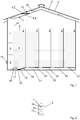
- FIG. 1 A device according to the invention for drying material to be dried is shown, the material to be dried being hay 1 in this case.
- the hay 1 is arranged in a ventilation box 2 between a start area 15 and an end area 16, the hay 1 being divided into a total of five ventilation boxes 2 in the exemplary embodiment shown.
- the ventilation boxes 2 are covered with a roof 3, so that the hay 1 is protected from the weather.
- the hay 1 rests on a box surface 22 in each ventilation box 2.
- Air can flow onto the box surface 22, for example by realizing the box surface 22 through a structural steel grille (not shown) which rests on grate girders (not shown) and is arranged at a certain distance, for example 40 cm, above a floor 23.
- a structural steel grille not shown
- grate girders not shown
- an air duct 21 is formed in the initial region 15, through which air can be blown onto the box surface 22 or into the ventilation box 2.
- each ventilation box 2 is equipped with an air guide flap 20, which either closes the box surface 22 or directs the air onto the box surface 22.
- the air guiding flaps 20 and the air duct 21 therefore act as air guiding means in order to selectively direct the air to a specific ventilation box 2.
- the in Fig. 1 shown device on a fan 4 the arrows in Fig. 1 symbolize possible air flows.
- the air to be blown into the ventilation boxes 2 is first sucked in by means of the fan 4, preferably all of the sucked-in air being sucked in by a dehumidifier 5 in which dehumidifier 5 the air is dehumidified.
- the device has a switching flap 6, which is arranged in the end region 16 and can be moved back and forth between a first position 7 and a second position 8 by means of an electric cylinder 10.
- first position 7 causes the switching flap 6 that air can only be sucked out of the ventilation boxes 2. This air is then fed to the dehumidifier 5 and back into a selected one Blown in ventilation box 2. This means that in this case there is a closed air circuit in the device.
- the air is preferably sucked in completely from the outside or from outside the ventilation boxes 2.
- an air duct 9 is formed under the roof 3 for this.
- the roof 3 is warm due to the solar radiation, the air sucked in from the outside can ultimately be warmed up - ultimately by solar energy.
- good heat conduction of the roof 3 is advantageous, which is why the roof 3 is preferably made from sheet metal, particularly preferably from trapezoidal sheets.
- the changeover flap 6 thus makes it possible to use air which can be sucked in from outside in order to contribute to reaching a desired temperature of the air in the ventilation box 2 or in its start region 15 and / or end region 16, ie to achieve a desired internal temperature.
- Sensors 17 are provided in the start area 15 and in the end area 16 to control the inside temperature and the air humidity in the ventilation box 2 and the drying progress.
- a temperature sensor 24 is provided in the air duct 9 in front of the switching flap 6 in order to measure an outside temperature of the air drawn in from outside.
- a sensor 17 is used instead of the temperature sensor 24 in order to also measure the relative air humidity of the air sucked in from outside directly in the air duct 9. Outside temperature and inside temperature can be compared.
- the outside temperature is compared with the inside temperature, preferably in the end region 16. If the difference between the outside temperature and the inside temperature is greater than a specifiable positive differential temperature threshold, e.g. 3 ° C, the changeover flap 6 is brought into the second position 8 in order to draw in warm air from outside the ventilation box 2.
- a specifiable positive differential temperature threshold e.g. 3 ° C
- the dehumidifier 5 only has to be switched on when the relative air humidity of the air drawn in from outside is more than 50%.
- the changeover flap 6 is brought into the first position 7 in order to prevent the air in the interior of the ventilation box 2 from cooling.
- the air in the ventilation box 2 or the items to be dried can of course also be specifically cooled by moving the changeover flap 6 to the second position 8 if the difference between the outside temperature and the inside temperature is negative.
- the dehumidifier 5 which in Fig. 2 is shown schematically, the arrow indicating the flow direction of the air.
- the dehumidifier 5 has an evaporator 11, in which refrigerant (not shown) is evaporated by the heat of the intake air.
- the intake air is below the dew point cooled, and water condenses on the cold surface of the evaporator 11, from where it runs off or drips off.
- the dehumidifier 5 has a condenser 12 in which the refrigerant condenses and thereby releases latent heat.
- the condenser 12 can be used as a heat source for heating the dehumidified air, in that the air, after it has passed the evaporator 11 and has been dehumidified, is also drawn through the condenser 12.
- the dehumidifier 5 comprises a compressor 13 in order to compress the refrigerant evaporated in the evaporator 11. Since the compressor 13 emits heat here, the compressor 13 is also suitable as an additional heat source, which can also be conveniently arranged between the evaporator 11 and the condenser 12, without significantly impairing the flow of air from the evaporator 11 to the condenser 12, see Fig. 2 .
- the inside temperature can also be raised if the outside temperature is lower than the inside temperature.
- the switching flap 6 is moved into the first position 7 and can be left there, e.g. as long as the inside temperature does not exceed a predeterminable inside temperature threshold.
- the air flow can be influenced by controlling the fan 4, ie the amount of air drawn in and thus the amount of air blown into the ventilation boxes 2 can be regulated.
- air throughputs or quantities of air drawn in should be set from 200 m 3 / h per square meter of box area 22, m B 2 to 600 m 3 / h / m B 2 , preferably 400 m 3 / h / m B 2 .
- the density of the hay 1 can vary - typically between 100 kg / m 3 to 250 kg / m 3 - which is accompanied by a different resistance for the air blown into the ventilation boxes 2.
- the power or the speed of the fan 4 must be controllable, with frequency converters being provided according to the invention for this purpose (not shown).
- Frequency inverters are preferably also used to control the power of dehumidifier 5 or the compressor 13 of dehumidifier 5.
- a sensor 18 for measuring the speed of the air taken in is provided, which is preferably arranged in the dehumidifier 5, behind the evaporator 11. Since the cross section of the dehumidifier 5 through which the air can flow is known, the air throughput results directly from this.
- a pressure sensor 19 is arranged in the initial area 15 to monitor the pressure of the air that is blown into the ventilation boxes 2.
- the monitoring of the pressure in the initial region 15 or the resulting differential pressure between the initial region 15 and the final region 16, which is thus possible, can be used, for example, to ensure that a certain maximum permissible pressure in the initial region 15 or a certain maximum permissible pressure difference is not exceeded. This can occur if the density of the hay 1 is too high and the air throughput too high impaired. If necessary, the fan 4 can thus be regulated accordingly.
- a regulating control unit 14 see Fig. 1 , which is designed as a programmable logic controller.
- the control unit 14 processes the signals from all the sensors 17, the temperature sensor 18 and the pressure sensor 19.
- the design of the control unit 14 as a programmable logic controller also makes it possible to take into account the current amount of hay 1 to be dried and threshold values for inside temperature and outside temperature To specify or adjust air humidity and air throughput.
- the control unit 14 controls the switchover flap 6 and regulates the output of the fan 4 and the ventilator 5.
- the control unit 14 can control the air flaps 20 in order to dry the hay 1 in intervals to enable individual ventilation boxes 2. In this way, the drying of the hay 1 is carried out in a highly automated and optimized manner.
Landscapes
- Engineering & Computer Science (AREA)
- Mechanical Engineering (AREA)
- General Engineering & Computer Science (AREA)
- Life Sciences & Earth Sciences (AREA)
- Microbiology (AREA)
- Environmental Sciences (AREA)
- Health & Medical Sciences (AREA)
- Sustainable Development (AREA)
- Toxicology (AREA)
- Drying Of Solid Materials (AREA)
- Drying Of Gases (AREA)
Description
- Die vorliegende Erfindung betrifft eine Vorrichtung zum Trocknen von Heu, umfassend eine Belüftungsbox zur Aufnahme des Heus, wobei die Belüftungsbox mit einem Dach überdacht ist, die Vorrichtung weiters umfassend zumindest einen Ventilator, durch welchen Ventilator Luft ansaugbar ist, wobei die angesaugte Luft zumindest teilweise einem Luftentfeuchter zuführbar ist, um die Luft zu entfeuchten, und wobei mittels des mindestens einen Ventilators die Luft schließlich durch die Belüftungsbox, von einem Anfangsbereich zu einem Endbereich der Belüftungsbox blasbar ist, wobei das Heu zwischen Anfangsbereich und Endbereich auf einer durch die Luft anströmbaren Boxenfläche anordenbar ist, wobei eine Umschaltklappe vorgesehen ist, die von einer ersten Position in eine zweite Position bewegbar ist, wobei in der ersten Position die Luft durch den mindestens einen Ventilator lediglich aus der Belüftungsbox ansaugbar ist, um einen geschlossenen Luftkreislauf in der Vorrichtung auszubilden, und wobei in der zweiten Position die Luft zumindest teilweise von außerhalb der Belüftungsbox ansaugbar ist, wobei mehrere, vorzugsweise fünf Belüftungsboxen vorgesehen sind, wobei Luftleitmittel vorgesehen sind, um die Luft wahlweise zu einer bestimmten Belüftungsbox zu leiten, wobei weiters eine Regel-Steuereinheit, die vorzugsweise als speicherprogrammierbare Steuerung ausgeführt ist, vorgesehen ist, mittels welcher der mindestens eine Ventilator und der Luftentfeuchter ansteuerbar und/oder regelbar sind, und wobei die Luftleitmittel mindestens eine Luftleitklappe umfassen, die mittels der Regel-Steuereinheit ansteuerbar ist.
- Bei der Trocknung von Trocknungsgut, insbesondere von Heu, das in der Landwirtschaft als ideales Futter für Rinder eingesetzt werden kann, ist es bekannt, Luft zu entfeuchten und durch das Trocknungsgut zu blasen. Hierfür wird das Trocknungsgut in einer Belüftungsbox platziert. Die Luft wird über einen Ventilator angesaugt, einem Luftentfeuchter zugeführt und anschließend in die Belüftungsbox eingeblasen. Um die Trocknung zu beschleunigen, wird die zur Trocknung verwendete Luft angeheizt, wofür beispielsweise eine elektrische Heizung oder ein Hackgutofen verwendet wird. Nachteilig hierbei ist jedoch der hohe Energieeinsatz, der mit der Trocknung einhergeht. Insbesondere wenn sehr große Luftmengen zur Trocknung notwendig sind, kann die Trocknung mitunter nicht mehr wirtschaftlich durchgeführt werden.
- Aus dem Stand der Technik ist die
GB 2463747 A - Weiters ist aus dem Stand der Technik die
US 1989530 A bekannt, die eine Vorrichtung zur Lagerung von Heu betrifft, wobei auch eine Trocknung erfolgen kann. Dabei wird das Heu in einen Metallbehälter aufgegeben, wobei das Heu auf einem Rost mit Stäben aufliegt. Durch den Rost wird mittels eines Gebläses Luft geblasen, die zuvor gezielt gekühlt oder angewärmt wird. Der Behälter weist vertikal voneinander beabstandete Türen/Öffnungen auf, die geöffnet werden können, um Frischluft zur angewärmten Luft zuzumischen. - Aus der
JP 3005777 B2 - Es ist daher Ziel der vorliegenden Erfindung, eine verbesserte Vorrichtung und ein verbessertes Verfahren zur Verfügung zu stellen, welche das Trocknen von Trocknungsgut bei geringem Energieeinsatz und gleichzeitig hohen Luftmengen bzw. hohem Trocknungseffekt erlauben.
- Zum Trocknen von Trocknungsgut, vorzugsweise Heu, wird das Trocknungsgut in eine Belüftungsbox zwischen einem Anfangsbereich und einen Endbereich der Belüftungsbox aufgegeben. Die Belüftungsbox schützt das Trocknungsgut vor Witterungseinflüssen von außerhalb der Belüftungsbox und ist entsprechend mit einem Dach ausgestattet. Dabei ist das Trocknungsgut auf einer anströmbaren Boxenfläche angeordnet, wobei die anströmbare Boxenfläche nicht notwendigerweise eine horizontale Fläche sein muss, sondern auch eine vertikale Fläche oder eine schräge Fläche mit einer Neigung zwischen der Horizontalen und der Vertikalen sein kann. Luft zum Trocknen wird mit mindestens einem Ventilator angesaugt und zumindest teilweise einem Luftentfeuchter zugeführt. Anschließend wird die Luft mit dem mindestens einen Ventilator durch die Belüftungsbox, vom Anfangsbereich zum Endbereich geblasen.
- Der Erfindung liegt nun die Idee zugrunde, ohnehin vorhandene Wärmequellen gezielt und in kontrollierter Weise auszunutzen, um die Luft für das Trocknen anzuwärmen. Insbesondere soll Luft, die von außen, d.h. von außerhalb der Belüftungsbox, angesaugt wird, mit vorhandenen Wärmequellen angewärmt werden. Vorzugsweise wird für das Anwärmen der von außen angesaugten Luft Sonnenenergie verwendet. Diese Luft wird jedoch nur dann dem Entfeuchter bzw. einem Luftkreislauf in der Belüftungsbox zugeführt, wenn sie warm genug ist, da es sonst zu einer Abkühlung der Lufttemperatur in der Belüftungsbox käme.
- Daher ist es bei einer Vorrichtung zum Trocknen von Trocknungsgut, umfassend eine Belüftungsbox zur Aufnahme des Trocknungsguts, wobei die Belüftungsbox mit einem Dach überdacht ist, die Vorrichtung weiters umfassend zumindest einen Ventilator, durch welchen Ventilator Luft ansaugbar ist, wobei die angesaugte Luft zumindest teilweise einem Luftentfeuchter zuführbar ist, um die Luft zu entfeuchten, und wobei mittels des mindestens einen Ventilators die Luft schließlich durch die Belüftungsbox, von einem Anfangsbereich zu einem Endbereich der Belüftungsbox blasbar ist, wobei das Trocknungsgut zwischen Anfangsbereich und Endbereich auf einer durch die Luft anströmbaren Boxenfläche anordenbar ist, erfindungsgemäß vorgesehen, dass eine Umschaltklappe vorgesehen ist, die von einer ersten Position in eine zweite Position bewegbar ist, wobei in der ersten Position die Luft durch den mindestens einen Ventilator lediglich aus der Belüftungsbox ansaugbar ist, um einen geschlossenen Luftkreislauf in der Vorrichtung auszubilden, und wobei in der zweiten Position die Luft zumindest teilweise von außerhalb der Belüftungsbox ansaugbar ist.
- Vorzugsweise wird zur Steuerung der Umschaltklappe eine Außentemperatur, d.h. die Temperatur der von außerhalb der Belüftungsbox angesaugten Luft, und/oder eine Innentemperatur, d.h. die Temperatur der Luft in der Belüftungsbox, und/oder die Differenz zwischen Außentemperatur und Innentemperatur herangezogen. Entsprechend ist es bei einem Verfahren zum Trocknen von Trocknungsgut erfindungsgemäß vorgesehen, dass eine erfindungsgemäße Vorrichtung verwendet wird und das Trocknungsgut in die Belüftungsbox aufgegeben wird und dass eine Außentemperatur der von außerhalb der Belüftungsbox ansaugbaren Luft gemessen wird, wobei eine Innentemperatur der in der Belüftungsbox befindlichen Luft, vorzugsweise im Endbereich gemessen wird und wobei die Umschaltkappe in Abhängigkeit von der Außentemperatur und/oder der Innentemperatur und/oder der Differenz zwischen der Außentemperatur und der Innentemperatur von der ersten Position in die zweite Position und umgekehrt bewegt wird. Ausführungsformen, bei denen nur die Außentemperatur oder nur die Innentemperatur zur Steuerung der Umschaltklappe herangezogen wird, können sich dabei als besonders einfach im Aufbau erweisen.
- Um die Innentemperatur ansteigen bzw. nicht fallen zu lassen, ist es bei einer bevorzugten Ausführungsform des erfindungsgemäßen Verfahrens vorgesehen, dass die Umschaltklappe in die zweite Position bewegt oder in der zweiten Position gehalten wird, wenn die Außentemperatur größer gleich einem Außentemperaturschwellwert ist und/oder wenn die Differenz zwischen Außentemperatur und Innentemperatur größer gleich einem positiven Differenztemperaturschwellwert ist. Grundsätzlich ist es natürlich auch denkbar, dass die Umschaltklappe in die zweite Position bewegt oder in der zweiten Position gehalten wird, wenn die Innentemperatur kleiner gleich einem gewissen Innentemperaturschwellwert ist.
- In Versuchen wurden Außentemperaturschwellwerte und positive Differenztemperaturschwellwerte ermittelt, welche ein zügiges Aufschaukeln der Innentemperatur ergeben. Demgemäß ist es bei einer besonders bevorzugten Ausführungsform des erfindungsgemäßen Verfahrens vorgesehen, dass der Außentemperaturschwellwert zwischen 22°C und 27°C, vorzugsweise bei 25°C liegt und der positive Differenztemperaturschwellwert zwischen 2°C und 5°C, vorzugsweise bei 3°C. Es sei in diesem Zusammenhang nochmals betont, dass es für ein Aufschaukeln der Innentemperatur mitunter ausreicht, wenn nur die Differenz zwischen Außentemperatur und Innentemperatur größer gleich dem positiven Differenztemperaturschwellwert ist. Beispielsweise konnte bei Versuchen ein Aufschaukeln der Innentemperatur auch bei Außentemperaturen erreicht werden, die deutlich kleiner als die angegebenen Werte für den Außentemperaturschwellwert waren, wobei z.B. von einer Innentemperatur von 12°C ausgegangen wurde.
- Umgekehrt ermöglicht es die Umschaltklappe auch, gezielt kühle Luft von außen anzusaugen, ggf. zu entfeuchten und in die Belüftungsbox einzublasen, wenn die Temperatur in der Belüftungsbox gezielt gesenkt werden soll. Daher ist es bei einer bevorzugten Ausführungsform des erfindungsgemäßen Verfahrens vorgesehen, dass die Umschaltklappe in die zweite Position bewegt oder in der zweiten Position gehalten wird, wenn die Differenz zwischen Außentemperatur und Innentemperatur kleiner gleich einem negativen Differenztemperaturschwellwert ist. Selbstverständlich ist es bei besonders einfach gestalteten Ausführungsformen natürlich auch denkbar, dass die Umschaltklappe in die zweite Position bewegt oder in der zweiten Position gehalten wird, wenn die Innentemperatur größer als ein gewisser Innentemperaturschwellwert ist und/oder die Außentemperatur kleiner als ein gewisser Außentemperaturschwellwert.
- In Versuchen wurden negative Differenztemperaturschwellwerte ermittelt, welche eine zügige Reduktion der Innentemperatur gewährleisten. Demgemäß ist es bei einer besonders bevorzugten Ausführungsform des erfindungsgemäßen Verfahrens vorgesehen, dass der negative Differenztemperaturschwellwert zwischen -5°C und -2°C, vorzugsweise bei -3°C liegt.
- Um zum Anwärmen der von außerhalb der Belüftungsbox ansaugbaren Luft Sonnenenergie optimal einzusetzen, ist es bei einer bevorzugten Ausführungsform der erfindungsgemäßen Vorrichtung vorgesehen, dass unter dem Dach ein Luftkanal vorgesehen ist, um die in der zweiten Position von außerhalb der Belüftungsbox ansaugbare Luft unter dem Dach entlang zu leiten und Wärmeübertragung zwischen dem Dach und der Luft zu ermöglichen. Durch das Dach kann auf konstruktiv einfache Weise eine große Fläche zur Verfügung gestellt werden, die von der Sonne beschienen wird. Entsprechend kann die von außen angesaugte Luft selbst bei mäßiger Sonneneinstrahlung sehr gut angewärmt werden, bevor sie dem Luftentfeuchter zugeführt wird.
- Um die Sonnenenergie effizient nutzen zu können, ist eine gute Wärmeleitung des Daches vorteilhaft. Entsprechend ist Blech eine gute Materialwahl. Zudem bieten Trapezbleche eine konstruktiv einfache und relativ kostengünstige Möglichkeit für die Ausbildung eines Daches. Daher ist es bei einer bevorzugten Ausführungsform der erfindungsgemäßen Vorrichtung vorgesehen, dass das Dach als Blechdach, vorzugsweise aus Trapezblechen ausgeführt ist.
- Bei hinreichend hohen Außentemperaturen bzw. Temperaturen außerhalb der Belüftungsbox ist es ausreichend, die Luft ausschließlich von außen bzw. über den Luftkanal unter dem Dach anzusaugen, um trotzdem eine hinreichend hohe Temperatur in der Belüftungsbox zu realisieren. Entsprechend ist es bei einer bevorzugten Ausführungsform der erfindungsgemäßen Vorrichtung vorgesehen, dass in der zweiten Position die Luft lediglich von außerhalb der Belüftungsbox ansaugbar ist.
- Um ein bequemes und automatisierbares Bewegen der Umschaltklappe zu ermöglichen, ist es bei einer bevorzugten Ausführungsform der erfindungsgemäßen Vorrichtung vorgesehen, dass ein Zylinder, vorzugsweise ein elektrischer Zylinder vorgesehen ist, um die Umschaltklappe zwischen der ersten Position und der zweiten Position hin und her zu bewegen. Selbstverständlich sind auch anders betriebene Zylinder denkbar, beispielsweise hydraulische oder pneumatische Zylinder.
- Je nach relativer Luftfeuchtigkeit der von außen angesaugten Luft, kann mitunter auch darauf verzichtet werden, diese Luft mittels des Luftentfeuchters zu entfeuchten. Typischerweise muss der Luftentfeuchter erst bei einer relativen Luftfeuchtigkeit der von außen angesaugten Luft von mehr als 50% eingeschaltet werden. Hierbei besteht eine konstruktiv einfache Lösung darin, stets die gesamte angesaugte Luft durch den Luftentfeuchter zu führen und den Luftentfeuchter nur bei Bedarf einzuschalten. Dies ist unabhängig davon, in welcher Position sich die Umschaltklappe befindet, d.h. auch wenn keine Luft von außen, sondern nur aus der Belüftungsbox angesaugt wird. Daher ist es bei einer bevorzugten Ausführungsform der erfindungsgemäßen Vorrichtung vorgesehen, dass die gesamte angesaugte Luft dem Luftentfeuchter zuführbar ist.
- Der Luftentfeuchter weist einen Verdampfer auf, in welchem Kältemittel durch die Wärme der angesaugten Luft verdampft wird, wodurch die angesaugte Luft wiederum unter den Taupunkt abgekühlt wird. Entsprechend kondensiert Wasser auf der kalten Oberfläche des Verdampfers und rinnt bzw. tropft vom Verdampfer ab. Um auf diese Weise möglichst die gesamte angesaugte Luft entfeuchten zu können, ist es bei einer bevorzugten Ausführungsform der erfindungsgemäßen Vorrichtung vorgesehen, dass der Luftentfeuchter einen Verdampfer und einen Kondensator aufweist, wobei die dem Luftentfeuchter zugeführte Luft zumindest teilweise, vorzugsweise vollständig durch den Verdampfer führbar ist.
- Es sei bemerkt, dass diese Art der Entfeuchtung auch dazu verwendet werden kann, das in der Belüftungsbox befindliche Trocknungsgut gezielt zu kühlen, indem die Luft, nachdem sie durch den Verdampfer geführt, entfeuchtet und gekühlt worden ist, ohne ein darauf folgendes Anwärmen direkt in die Belüftungsbox bzw. in den Anfangsbereich der Belüftungsbox eingeblasen wird.
- Umgekehrt ist es für ein rasches Trocknen von Vorteil, die entfeuchtete Luft anzuwärmen, bevor sie in die Belüftungsbox eingeblasen wird. Daher ist es bei einer bevorzugten Ausführungsform des erfindungsgemäßen Verfahrens vorgesehen, dass die Luft, nachdem sie durch den Verdampfer geführt worden ist, angewärmt wird.
- Soll die entfeuchtete Luft angewärmt werden, geschieht dies auf konstruktiv einfachstem Wege, indem die entfeuchtete Luft durch den Kondensator geleitet wird, in welchem das Kältemittel kondensiert und dabei latente Wärme abgibt, wodurch der Kondensator als Wärmequelle genutzt werden kann. Daher ist es bei einer bevorzugten Ausführungsform der erfindungsgemäßen Vorrichtung vorgesehen, dass der Verdampfer und Kondensator derart angeordnet sind, dass die dem Luftentfeuchter zugeführte Luft sowohl durch den Verdampfer als auch durch den Kondensator führbar ist. Somit kann auch in diesem Fall eine ohnehin vorhandene Wärmequelle, nämlich der Kondensator, für das Anwärmen der angesaugten bzw. in die Belüftungsbox einzublasenden Luft verwendet werden.
- Darüberhinaus ist es selbstverständlich möglich, eine weitere Wärmequelle zum zusätzlichen Anwärmen der entfeuchteten Luft vorzusehen. Um eine besonders kompakte Anordnung zu realisieren, ist es bei einer bevorzugten Ausführungsform der erfindungsgemäßen Vorrichtung vorgesehen, dass zwischen Verdampfer und Kondensator eine Wärmequelle angeordnet ist, um die durch den Verdampfer durchgetretene Luft zusätzlich anzuwärmen.
- Doch auch in diesem Fall, muss nicht unbedingt auf eine zusätzliche Heizung, z.B. eine zusätzliche elektrische Heizung, zurückgegriffen werden. Dies deshalb, da der Luftentfeuchter einen Kompressor umfasst, um das im Verdampfer verdampfte Kältemittel zu komprimieren. Da der Kompressor hierbei Wärme abgibt, eignet sich also auch der Kompressor als zusätzliche Wärmequelle, die zudem bequem zwischen Verdampfer und Kondensator untergebracht werden kann, ohne die Strömung der Luft vom Verdampfer zum Kondensator wesentlich zu beeinträchtigen. Daher ist es bei einer bevorzugten Ausführungsform der erfindungsgemäßen Vorrichtung vorgesehen, dass der Luftentfeuchter einen Kompressor umfasst, der zumindest teilweise, vorzugsweise vollständig die Wärmequelle ausbildet. Auch dies trägt zur Ausnutzung möglichst aller ohnehin vorhandenen Wärmequellen für das Anwärmen von angesaugter Luft bei.
- Um den Trocknungsvorgang steuern zu können, ist es wünschenswert, den Luftdurchsatz einstellen zu können. Dies kann grundsätzlich durch eine Steuerung des Ventilators erfolgen, womit die Menge an angesaugter Luft und damit die Menge an in die Belüftungsbox eingeblasener Luft reguliert werden kann. Hierbei ist zu berücksichtigen, dass die Dichte an aufgebebenem Trocknungsgut variieren kann, womit ein unterschiedlicher Widerstand für die in die Belüftungsbox eingeblasene Luft einhergeht. Daher ist es bei einer bevorzugten Ausführungsform der erfindungsgemäßen Vorrichtung vorgesehen, dass der mindestens eine Ventilator eine Drehzahlsteuerung aufweist, um die angesaugte Luftmenge auf einen vorgegebenen Wert einzustellen. Auf diese Weise lassen sich beispielsweise im Falle von Heu als Trocknungsgut Mengen von angesaugter Luft bzw. Luftdurchsätze von 200 m3/h pro Quadratmeter Boxenfläche, mB 2, bis 600 m3/h/mB 2, vorzugsweise 400 m3/h/mB 2 einstellen, wobei das Heu eine Dichte von typischerweise 100 kg/m3 bis 250 kg/m3 aufweisen kann.
- Bevorzugt liegt das Heu im Wesentlichen lose in der Belüftungsbox vor, d.h. insbesondere nicht in Form von Rundballen. Selbstverständlich ist aber auch die Trocknung des Heus in Rundballenform möglich. In diesem Fall wird die anströmbare Boxenfläche auf jene Fläche beschränkt, auf der der bzw. die Rundballen aufliegt bzw. aufliegen. Dies kann bevorzugt so realisiert werden, dass jeweils ein zu trocknender Rundballen über jeweils einer Öffnung im Anfangsbereich der Belüftungsbox angeordnet wird, wobei die für das Trocknen verwendete Luft durch die Öffnung in die Belüftungsbox bzw. direkt auf den jeweiligen Rundballen eingeblasen wird. Die Öffnung kann als kreisrundes Loch ausgeführt sein und ist auf den Durchmesser der Rundballen angepasst, d.h. der Durchmesser der Öffnung entspricht im Wesentlichen dem Durchmesser des Rundballens und beträgt daher z.B. zwischen 1,2 m und 2 m. Damit der Rundballen nicht in die Öffnung hinein fällt, kann die Öffnung beispielsweise mit einem Gitter abgedeckt sein. Entsprechend ergeben sich in diesem Fall Luftdurchsätze von 850 m3/h bis 2000 m3/h pro Öffnung bzw. pro Rundballen.
- Eine einfach zu realisierende Möglichkeit zur Steuerung der Drehzahl des Ventilators aber auch zur Leistung des Luftentfeuchters, wobei diese im Wesentlichen durch die Leistung des Kompressors bestimmt wird, bieten Frequenzumrichter. Daher ist es bei einer bevorzugten Ausführungsform der erfindungsgemäßen Vorrichtung vorgesehen, dass zur Steuerung des mindestens einen Ventilators und/oder des Luftentfeuchters Frequenzumrichter vorgesehen sind.
- Um die Menge an angesaugter Luft messen zu können, ist es bei einer bevorzugten Ausführungsform der erfindungsgemäßen Vorrichtung vorgesehen, dass ein Sensor zur Messung der Geschwindigkeit der angesaugten Luft vorgesehen ist, der vorzugsweise im Luftentfeuchter hinter dem Verdampfer angeordnet ist. Das Messergebnis kann in der Folge als Regelgröße zur Steuerung des mindestens einen Ventilators verwendet werden. Die Anordnung des Sensors hinter dem Verdampfer hat den Vorteil, dass der Verdampfer einen gewissen Schutz für den Sensor vor Staub bietet. Zudem erweist sich diese Sensoranordnung als besonders günstig, wenn stets die gesamte angesaugte Luftmenge dem Luftentfeuchter zugeführt wird, auch wenn dieser nicht betrieben wird, da der Luftentfeuchter eine definierte Querschnittsfläche darstellt, durch die die angesaugte Luftmenge durchtreten muss. Da diese Querschnittsfläche bekannt ist, kann durch Messung der Luftgeschwindigkeit im Luftentfeuchter unmittelbar auf die Menge der angesaugten Luft pro Zeit geschlossen werden.
- Weiters ist es bei einer besonders bevorzugten Ausführungsform der erfindungsgemäßen Vorrichtung vorgesehen, dass im Anfangsbereich ein Sensor zur Messung des Drucks der eingeblasenen Luft angeordnet ist. Die damit mögliche Überwachung des Drucks im Anfangsbereich bzw. des sich ergebenden Differenzdrucks zwischen Anfangsbereich und Endbereich kann beispielsweise dazu verwendet werden sicherzustellen, dass ein gewisser zulässiger Höchstdruck im Anfangsbereich bzw. eine gewisse höchstzulässige Druckdifferenz nicht überschritten wird. Dies kann dann auftreten, wenn die Dichte des Trocknungsguts zu hoch ist und den Luftdurchsatz zu stark beeinträchtigt. Gegebenenfalls kann somit der mindestens eine Ventilator entsprechend zurückgeregelt werden.
- Um den Trocknungsvorgang zu überwachen und automatisieren zu können, ist es bei einer bevorzugten Ausführungsform der erfindungsgemäßen Vorrichtung vorgesehen, dass sowohl im Anfangsbereich als auch im Endbereich Sensoren zur Messung der Temperatur und der Luftfeuchtigkeit vorgesehen sind. Wie oben ausgeführt, kann durch Vergleich mit der Außentemperatur bzw. der Temperatur der von außerhalb der Belüftungsbox ansaugbaren Luft entschieden werden, ob die Umschaltklappe in eine andere als die aktuelle Position bewegt werden soll.
- Um für eine Automatisierung des Trocknungsvorgangs die Signale sämtlicher Sensoren verarbeiten zu können, ist es bei einer bevorzugten Ausführungsform der erfindungsgemäßen Vorrichtung vorgesehen, dass eine Regel-Steuereinheit, die vorzugsweise als speicherprogrammierbare Steuerung ausgeführt ist, vorgesehen ist, mittels welcher der mindestens eine Ventilator, der Luftentfeuchter sowie die Umschaltklappe ansteuerbar und/oder regelbar sind. Die Ausführung als speicherprogrammierbare Steuerung ermöglicht es beispielsweise, die Menge an aktuell zu trocknenden Trocknungsgut zu berücksichtigen und Schwellwerte für Innentemperatur, Außentemperatur, Luftfeuchtigkeit und Luftdurchsatz vorzugeben bzw. anzupassen.
- Die erfindungsgemäße Vorrichtung kann um weitere Belüftungsboxen erweitert werden, was ein intervallweises Trocknen des Trocknungsguts in den unterschiedlichen Belüftungsboxen ermöglicht. D.h. die angesaugte Luft wird vorzugsweise nicht in alle Belüftungsboxen gleichzeitig eingeblasen, sondern immer nur in eine Belüftungsbox, wobei nach einer gewissen vorgebbaren Zeit die Luft zur nächsten Belüftungsbox geleitet bzw. in die nächste Belüftungsbox eingeblasen wird. Daher ist es bei einer bevorzugten Ausführungsform der erfindungsgemäßen Vorrichtung vorgesehen, dass mehrere, vorzugsweise fünf Belüftungsboxen vorgesehen sind, wobei Luftleitmittel vorgesehen sind, um die Luft wahlweise zu einer bestimmten Belüftungsbox zu leiten.
- Hierzu ist ein Luftkanal zum Anfangsbereich jeder Belüftungsbox vorgesehen sowie mindestens eine Luftleitklappe, um die Luft gezielt der gewünschten Belüftungsbox zuzuleiten. Weiters ist erfindungsgemäß vorgesehen, dass die mindestens eine Luftleitklappe mittels der Regel-Steuereinheit ansteuerbar ist.
- Indem das Trocknungsgut auf zwei oder mehrere Belüftungsboxen aufgeteilt wird, können mitunter deutlich kürzere Trocknungszeiten erzielt werden als bei Trocknung derselben Menge an Trocknungsgut in nur einer Belüftungsbox. Grund hierfür ist zum einen, dass das Trocknungsgut weniger dicht in den einzelnen Belüftungsboxen angeordnet werden kann als in nur einer einzigen Belüftungsbox.
- Zum anderen hat es sich gezeigt, dass Pflanzen, nachdem sie geschnitten worden sind, gespeichertes Wasser über Kapillarwirkung - zumindest über einen gewissen Zeitraum - kontinuierlich den Blättern zuführen, um eventuell noch eine Notreife bewirken zu können. Dies wiederum führt dazu, dass sich in einem ersten Zeitintervall, in dem das Heu z.B. in einer weiteren Belüftungsbox nicht getrocknet wird, eine erhöhte Feuchtigkeit in den Blättern bildet. Wenn nun in einem darauffolgenden zweiten Zeitintervall das Heu in dieser weiteren Belüftungsbox durch Einblasen von Luft getrocknet wird, wird insbesondere in einer relativ kurzen Anfangszeitspanne dieses zweiten Zeitintervalls eine erhöhte Menge an Feuchtigkeit dem Heu entzogen. Mit anderen Worten, indem das erste Zeitintervall lang zugewartet und erst dann getrocknet wird, wird in der relativ kurzen Anfangszeitspanne des zweiten Zeitintervalls derselbe Trocknungseffekt erzielt, wie wenn über das gesamte erste Zeitintervall kontinuierlich Luft zur Trocknung in die weitere Belüftungsbox eingeblasen worden wäre.
- Umgekehrt wird nun während des zweiten Zeitintervalls keine Luft in eine erste - und/oder zweite und/oder dritte und/oder vierte und/oder fünfte und/oder noch darüberhinaus gehende - Belüftungsbox eingeblasen, sodass sich eine erhöhte Feuchtigkeit in den Blättern des Heus in dieser Belüftungsbox bzw. diesen Belüftungsboxen bilden kann und so fort.
- Hierbei ist zu beachten, dass ein zu langes Zeitintervall, in dem keine Luft in eine gewisse Belüftungsbox eingeblasen wird, dazu führen kann, dass das zu trocknende Heu bzw. Trocknungsgut in dieser Belüftungsbox sich senkt und unerwünscht verdichtet. Hierzu haben Versuche ergeben, dass bei der intervallweisen Trocknung die Zeitintervalle ohne eingeblasene Luft nicht länger als zwei Stunden sein sollten.
- In Versuchen mit Heu konnten durch intervallweises Trocknen Zeitersparnisse von bis zu 40% erzielt werden.
- Selbstverständlich ist es aber auch denkbar, unterschiedliches Trocknungsgut in den unterschiedlichen Belüftungsboxen zu trocknen. Beispiele für unterschiedliches Trocknungsgut in den verschiedenen Belüftungsboxen wären: loses Heu; Heu in Rundballenform; Hackschnitzel; Hopfen; Getreide; Mais; Kräuter, insbesondere für Kräutertees; biogene Ausgangsmaterialien zur Erzeugung von Biogas; Schlachtabfälle oder Baustoffe.
- Wie bereits erwähnt, kann mittels der erfindungsgemäßen Vorrichtung bzw. mittels des erfindungsgemäßen Verfahrens unterschiedlichste Trocknungsgüter getrocknet werden, vorzugsweise organische Trocknungsgüter. Entsprechend ist erfindungsgemäß die Verwendung einer erfindungsgemäßen Vorrichtung zum Trocknen von Heu vorgesehen. Auf diese Weise können die Nährstoffe im Heu erhalten werden, insbesondere wenn das Heu bereits mit einer Restfeuchte eingefahren wird. Das Heu behält seinen aromatischen Duft, was sich vorteilhaft bei der Verfütterung an Milchkühe auswirkt, da die Tiere besonders viel von diesem Heu fressen und in der Folge mehr Energie haben, gesünder sind und mehr Milchleistung bringen. Ebenso ist erfindungsgemäß die Verwendung einer erfindungsgemäßen Vorrichtung zum Trocknen von Lebensmitteln vorgesehen. Als Spezialfall hiervon kann Hopfen angesehen werden bzw. ist erfindungsgemäß die Verwendung einer erfindungsgemäßen Vorrichtung zum Trocknen von Hopfen vorgesehen. Die erfindungsgemäße Trocknung ermöglicht auch in diesem Fall einen maximalen Erhalt des Aromas der Lebensmittel bzw. des Hopfens.
- Die Erfindung wird nun anhand eines Ausführungsbeispiels näher erläutert. Die Zeichnungen sind beispielhaft und sollen den Erfindungsgedanken zwar darlegen, ihn aber keinesfalls einengen oder gar abschließend wiedergeben.
- Dabei zeigt:
- Fig. 1
- eine schematische Ansicht einer erfindungsgemäßen Vorrichtung zum Trocknen von Heu
- Fig. 2
- eine schematische Ansicht eines Luftentfeuchters der erfindungsgemäßen Vorrichtung aus
Fig. 1 - In der schematischen Ansicht der
Fig. 1 ist eine erfindungsgemäße Vorrichtung zum Trocknen von Trocknungsgut dargestellt, wobei das Trocknungsgut in diesem Fall Heu 1 ist. Das Heu 1 ist in einer Belüftungsbox 2 zwischen einem Anfangsbereich 15 und einem Endbereich 16 angeordnet, wobei im gezeigten Ausführungsbeispiel das Heu 1 auf insgesamt fünf Belüftungsboxen 2 aufgeteilt ist. Die Belüftungsboxen 2 sind mit einem Dach 3 überdacht, sodass das Heu 1 vor Witterungseinflüssen geschützt ist. - In jeder Belüftungsbox 2 liegt das Heu 1 auf einer Boxenfläche 22 auf. Die Boxenfläche 22 ist mit Luft anströmbar, indem die Boxenfläche 22 beispielsweise durch ein Baustahlgitter (nicht dargestellt) realisiert wird, das auf Rostträgern (nicht dargestellt) aufliegt und in einem gewissen Abstand, beispielsweise 40 cm, über einem Boden 23 angeordnet ist. Hierdurch wird im Anfangsbereich 15 ein Luftkanal 21 ausgebildet, durch den Luft auf die Boxenfläche 22 bzw. in die Belüftungsbox 2 einblasbar ist.
- Im gezeigten Ausführungsbeispiel kann die Luft wahlweise einer bestimmten Belüftungsbox 2 zugeführt werden. Hierzu ist jede Belüftungsbox 2 mit einer Luftleitklappe 20 ausgestattet, die die Boxenfläche 22 entweder verschließt oder die Luft auf die Boxenfläche 22 leitet. Die Luftleitklappen 20 und der Luftkanal 21 fungieren daher als Luftleitmittel, um die Luft wahlweise zu einer bestimmten Belüftungsbox 2 zu leiten.
- Um die Luft in bzw. durch die Belüftungsboxen 2 zu blasen, weist die in
Fig. 1 gezeigte Vorrichtung einen Ventilator 4 auf, wobei die Pfeile inFig. 1 mögliche Luftströme symbolisieren. Die in die Belüftungsboxen 2 einzublasende Luft wird zunächst mittels des Ventilators 4 angesaugt, wobei vorzugsweise die gesamte angesaugte Luft durch einen Luftentfeuchter 5 gesaugt wird, in welchem Luftentfeuchter 5 die Luft entfeuchtet wird. - Erfindungsgemäß weist die Vorrichtung eine Umschaltklappe 6 auf, die im Endbereich 16 angeordnet ist und mittels eines elektrischen Zylinders 10 zwischen einer ersten Position 7 und einer zweiten Position 8 hin und her bewegt werden kann. In der in
Fig. 1 gezeigten ersten Position 7 bewirkt die Umschaltklappe 6, dass Luft lediglich aus den Belüftungsboxen 2 angesaugt werden kann. Diese Luft wird in der Folge dem Luftentfeuchter 5 zugeführt und wieder in eine ausgewählte Belüftungsbox 2 eingeblasen. D.h. es liegt in diesem Fall ein geschlossener Luftkreislauf in der Vorrichtung vor. - In der zweiten Position 8 hingegen, die in
Fig. 1 durch die strichlierte Linie angedeutet ist, wird die Luft vorzugsweise vollständig von außen bzw. von außerhalb der Belüftungsboxen 2 angesaugt. Konkret ist hierfür ein Luftkanal 9 unter dem Dach 3 ausgebildet. Durch das Entlangführen der von außen angesaugten Luft unter dem Dach 3 wird eine Wärmeübertragung zwischen dieser Luft und dem Dach 3 begünstigt. Wenn das Dach 3 aufgrund der Sonneneinstrahlung warm ist, kann auf diese Weise die von außen angesaugte Luft - letztlich durch Sonnenenergie - angewärmt werden. Um die Sonnenenergie besonders effizient nutzen zu können, ist eine gute Wärmeleitung des Daches 3 vorteilhaft, weshalb das Dach 3 vorzugsweise aus Blech, besonders bevorzugt aus Trapezblechen ausgeführt ist. Die Umschaltklappe 6 ermöglicht es somit, von außen ansaugbare Luft gezielt einzusetzen, um zum Erreichen einer gewünschten Temperatur der Luft in der Belüftungsbox 2 bzw. in deren Anfangsbereich 15 und/oder Endbereich 16, d.h. zum Erreichen einer gewünschten Innentemperatur, beizutragen. - Zur Kontrolle der Innentemperatur sowie der Luftfeuchtigkeit in der Belüftungsbox 2 bzw. des Trocknungsfortschritts sind Sensoren 17 im Anfangsbereich 15 und im Endbereich 16 vorgesehen. Darüberhinaus ist ein Temperaturfühler 24 im Luftkanal 9 vor der Umschaltklappe 6 vorgesehen, um eine Außentemperatur der von außen angesaugten Luft zu messen. Natürlich sind Ausführungsvarianten denkbar, in denen statt des Temperaturfühlers 24 ein Sensor 17 verwendet wird, um außerdem die relative Luftfeuchtigkeit der von außen angesaugten Luft direkt im Luftkanal 9 zu messen. Außentemperatur und Innentemperatur können miteinander verglichen werden.
- Soll nun beispielsweise die Luft in der Belüftungsbox 2 angewärmt werden, um eine schnellere Trocknung zu ermöglichen, wird die Außentemperatur mit der Innentemperatur, vorzugsweise im Endbereich 16, verglichen. Ist die Differenz zwischen Außentemperatur und Innentemperatur größer als ein vorgebbarer positiver Differenztemperaturschwellwert, z.B. 3°C, wird die Umschaltklappe 6 in die zweite Position 8 gebracht, um gezielt warme Luft von außerhalb der Belüftungsbox 2 anzusaugen.
- Es sei bemerkt, dass je nach relativer Luftfeuchtigkeit der von außen angesaugten Luft mitunter auch darauf verzichtet werden kann, diese Luft mittels des Luftentfeuchters 5 zu entfeuchten. Typischerweise muss der Luftentfeuchter 5 erst bei einer relativen Luftfeuchtigkeit der von außen angesaugten Luft von mehr als 50% eingeschaltet werden.
- Ist die Differenz zwischen Außentemperatur und Innentemperatur hingegen nicht groß genug oder gar negativ, wird die Umschaltklappe 6 in die erste Position 7 gebracht, um eine Abkühlung der Luft im Inneren der Belüftungsbox 2 zu vermeiden.
- Allerdings kann die Luft in der Belüftungsbox 2 bzw. das Trocknungsgut natürlich auch gezielt gekühlt werden, indem die Umschaltklappe 6 in die zweite Position 8 gebracht wird, wenn die Differenz von Außentemperatur und Innentemperatur negativ ist.
- Ist die von außen angesaugte Luft nicht warm genug oder soll die Innentemperatur schneller angehoben werden, können weitere, ohnehin vorhandene Wärmequellen zum Anwärmen der Luft genutzt werden. Hierzu bietet sich der Luftentfeuchter 5 an, der in
Fig. 2 schematisch gezeigt ist, wobei der Pfeil die Strömungsrichtung der Luft anzeigt. Der Luftentfeuchter 5 weist einen Verdampfer 11 auf, in welchem Kältemittel (nicht dargestellt) durch die Wärme der angesaugten Luft verdampft wird. Hierdurch wird die angesaugte Luft unter den Taupunkt abgekühlt, und Wasser kondensiert auf der kalten Oberfläche des Verdampfers 11, von wo es abrinnt bzw. abtropft. Weiters weist der Luftentfeuchter 5 einen Kondensator 12 auf, in welchem das Kältemittel kondensiert und dabei latente Wärme abgibt. Hierdurch kann der Kondensator 12 als Wärmequelle zum Anwärmen der entfeuchteten Luft genutzt werden, in dem die Luft, nachdem sie den Verdampfer 11 passiert hat und entfeuchtet worden ist, auch durch den Kondensator 12 gesaugt wird. - Darüberhinaus umfasst der Luftentfeuchter 5 einen Kompressor 13, um das im Verdampfer 11 verdampfte Kältemittel zu komprimieren. Da der Kompressor 13 hierbei Wärme abgibt, eignet sich auch der Kompressor 13 als zusätzliche Wärmequelle, die zudem bequem zwischen Verdampfer 11 und Kondensator 12 angeordnet werden kann, ohne die Strömung der Luft vom Verdampfer 11 zum Kondensator 12 wesentlich zu beeinträchtigen, siehe
Fig. 2 . - Durch Nutzung des Kondensators 12 sowie des Kompressors 13 als - ohnehin vorhandene - Wärmequellen, kann die Innentemperatur auch dann angehoben werden, wenn die Außentemperatur kleiner als die Innentemperatur ist. In diesem Fall wird die Umschaltklappe 6 in die erste Position 7 bewegt und kann dort belassen werden, z.B. solange die Innentemperatur nicht einen vorgebbaren Innentemperaturschwellwert übersteigt.
- Versuche haben gezeigt, dass durch gezielte Nutzung des Kondensators 12 sowie des Kompressors 13 als ohnehin vorhandene Wärmequellen auf zusätzliche Wärmequellen, etwa in Form einer zusätzlichen elektrischen Heizung, zumeist gänzlich verzichtet werden kann und dennoch hervorragende Trocknungsergebnisse bzw. hohe Trocknungseffekte erzielt werden.
- Ein weiterer zu beachtender Punkt bei der Steuerung des Trocknungsvorgangs ist der Luftdurchsatz. Der Luftdurchsatz kann durch eine Steuerung des Ventilators 4 beeinflusst werden, d.h. die Menge an angesaugter Luft und damit die Menge an in die Belüftungsboxen 2 eingeblasener Luft kann reguliert werden. Üblicherweise sollen Luftdurchsätze bzw. Mengen an angesaugter Luft von 200 m3/h pro Quadratmeter Boxenfläche 22, mB 2, bis 600 m3/h/mB 2, vorzugsweise 400 m3/h/mB 2 eingestellt werden. Hierbei ist zu berücksichtigen, dass die Dichte des Heus 1 variieren kann - typischerweise zwischen 100 kg/m3 bis 250 kg/m3 -, womit ein unterschiedlicher Widerstand für die in die Belüftungsboxen 2 eingeblasene Luft einhergeht. Entsprechend muss die Leistung bzw. die Drehzahl des Ventilators 4 steuerbar sein, wobei hierfür erfindungsgemäß Frequenzumrichter vorgesehen sind (nicht dargestellt). Vorzugsweise werden Frequenzumrichter außerdem auch zur Steuerung der Leistung Luftentfeuchters 5 bzw. des Kompressors 13 des Luftentfeuchters 5 eingesetzt.
- Zur Bestimmung des Luftdurchsatzes bzw. der angesaugten Luftmenge ist ein Sensor 18 zur Messung der Geschwindigkeit der angesaugten Luft vorgesehen, der vorzugsweise im Luftentfeuchter 5, hinter dem Verdampfer 11 angeordnet ist. Da der von der Luft durchströmbare Querschnitt des Luftentfeuchters 5 bekannt ist, ergibt sich daraus unmittelbar der Luftdurchsatz.
- Weiters ist zur Überwachung des Drucks der Luft, die in die Belüftungsboxen 2 eingeblasen wird, im Anfangsbereich 15 ein Drucksensor 19 angeordnet. Die damit mögliche Überwachung des Drucks im Anfangsbereich 15 bzw. des sich ergebenden Differenzdrucks zwischen Anfangsbereich 15 und Endbereich 16 kann beispielsweise dazu verwendet werden sicherzustellen, dass ein gewisser zulässiger Höchstdruck im Anfangsbereich 15 bzw. eine gewisse höchstzulässige Druckdifferenz nicht überschritten wird. Dies kann dann auftreten, wenn die Dichte des Heus 1 zu hoch ist und den Luftdurchsatz zu stark beeinträchtigt. Gegebenenfalls kann somit der Ventilator 4 entsprechend zurückgeregelt werden.
- Sämtliche Regel- und Steuervorgänge werden im gezeigten Ausführungsbeispiel durch eine Regel-Steuereinheit 14 kontrolliert, siehe
Fig. 1 , die als speicherprogrammierbare Steuerung ausgeführt ist. Die Regel-Steuereinheit 14 verarbeitet die Signale sämtlicher Sensoren 17, des Temperaturfühlers 18 sowie des Drucksensors 19. Die Ausführung der Regel-Steuereinheit 14 als speicherprogrammierbare Steuerung ermöglicht es zudem, die aktuelle Menge des zu trocknenden Heus 1 zu berücksichtigen und Schwellwerte für Innentemperatur, Außentemperatur, Luftfeuchtigkeit und Luftdurchsatz vorzugeben bzw. anzupassen. Basierend auf diesen Daten bzw. Angaben steuert die Regel-Steuereinheit 14 die Umschaltklappe 6 an und regelt die Leistung des Ventilators 4 sowie des Entlüfters 5. Zudem kann die Regel-Steuereinheit 14 die Luftleitklappen 20 ansteuern, um ein intervallweises Trocknen des Heus 1 in den einzelnen Belüftungsboxen 2 zu ermöglichen. Auf diese Weise wird die Trocknung des Heus 1 hochgradig automatisiert und optimiert durchgeführt. -
- 1
- Heu
- 2
- Belüftungsbox
- 3
- Dach
- 4
- Ventilator
- 5
- Luftentfeuchter
- 6
- Umschaltklappe
- 7
- Erste Position der Umschaltklappe
- 8
- Zweite Position der Umschaltklappe
- 9
- Luftkanal
- 10
- Elektrischer Zylinder
- 11
- Verdampfer
- 12
- Kondensator
- 13
- Kompressor
- 14
- Regel-Steuereinheit
- 15
- Anfangsbereich
- 16
- Endbereich
- 17
- Sensor zur Messung von Temperatur und Luftfeuchtigkeit
- 18
- Sensor zur Messung der Geschwindigkeit der angesaugten Luft
- 19
- Drucksensor
- 20
- Luftleitklappe
- 21
- Luftkanal im Anfangsbereich
- 22
- Boxenfläche
- 23
- Boden
- 24
- Temperaturfühler
Claims (6)
- Vorrichtung zum Trocknen von Heu (1), umfassend eine Belüftungsbox (2) zur Aufnahme des Heus (1), wobei die Belüftungsbox (2) mit einem Dach (3) überdacht ist, die Vorrichtung weiters umfassend zumindest einen Ventilator (4), durch welchen Ventilator (4) Luft ansaugbar ist, wobei die angesaugte Luft zumindest teilweise einem Luftentfeuchter (5) zuführbar ist, um die Luft zu entfeuchten, und wobei mittels des mindestens einen Ventilators (4) die Luft schließlich durch die Belüftungsbox (2), von einem Anfangsbereich (15) zu einem Endbereich (16) der Belüftungsbox (2) blasbar ist, wobei das Heu (1) zwischen Anfangsbereich (15) und Endbereich (16) auf einer durch die Luft anströmbaren Boxenfläche (22) anordenbar ist, wobei eine Umschaltklappe (6) vorgesehen ist, die von einer ersten Position (7) in eine zweite Position (8) bewegbar ist, wobei in der ersten Position (7) die Luft durch den mindestens einen Ventilator (4) lediglich aus der Belüftungsbox (2) ansaugbar ist, um einen geschlossenen Luftkreislauf in der Vorrichtung auszubilden, und wobei in der zweiten Position (8) die Luft zumindest teilweise von außerhalb der Belüftungsbox (2) ansaugbar ist, wobei mehrere, vorzugsweise fünf Belüftungsboxen (2) vorgesehen sind, wobei Luftleitmittel (20, 21) vorgesehen sind, um die Luft wahlweise zu einer bestimmten Belüftungsbox (2) zu leiten, wobei weiters eine Regel-Steuereinheit (14), die vorzugsweise als speicherprogrammierbare Steuerung ausgeführt ist, vorgesehen ist, mittels welcher der mindestens eine Ventilator (4) und der Luftentfeuchter (5) ansteuerbar und/oder regelbar sind, und wobei die Luftleitmittel mindestens eine Luftleitklappe (20) umfassen, die mittels der Regel-Steuereinheit (14) ansteuerbar ist, dadurch gekennzeichnet, dass die Umschaltklappe (6) mittels der Regel-Steuereinheit (14) ansteuerbar und/oder regelbar ist und dass die mindestens eine Luftleitklappe (20) mittels der Regel-Steuereinheit (14) derart ansteuerbar ist, um das Heu (1) in den unterschiedlichen Belüftungsboxen (2) intervallweise zu trocknen, wobei die mindestens eine Luftleitklappe (20) mittels der Regel-Steuereinheit (14) derart ansteuerbar ist, um das Heu (1) in einer der Belüftungsboxen (2) während eines ersten Zeitintervalls nicht zu trocknen und in einem darauffolgenden zweiten Zeitintervall durch Einblasen von Luft in diese Belüftungsbox (2) zu trocknen.
- Vorrichtung nach Anspruch 1, dadurch gekennzeichnet, dass für jede Belüftungsbox (2) eine Luftleitklappe (20) vorgesehen ist, die mittels der Regel-Steuereinheit (14) ansteuerbar ist.
- Vorrichtung nach einem der Ansprüche 1 bis 2, dadurch gekennzeichnet, dass die mindestens eine Luftleitklappe (20) mittels der Regel-Steuereinheit (14) derart ansteuerbar ist, um die Luft nur in eine der Belüftungsboxen einzublasen und nach einer gewissen vorgebbaren Zeit die Luft zur nächsten Belüftungsbox zu leiten und in diese einzublasen.
- Vorrichtung nach einem der Ansprüche 1 bis 3, dadurch gekennzeichnet, dass das erste Zeitintervall maximal 2 h lang ist.
- Vorrichtung nach einem der Ansprüche 1 bis 4, dadurch gekennzeichnet, dass die unterschiedlichen Belüftungsboxen (2) zur Trocknung von unterschiedlichem Trocknungsgut vorgesehen sind.
- Vorrichtung nach einem der Ansprüche 1 bis 5, dadurch gekennzeichnet, dass ein Sensor (18) zur Messung der Geschwindigkeit der angesaugten Luft vorgesehen ist, der im Luftentfeuchter (5) hinter dem Verdampfer (11) angeordnet ist.
Applications Claiming Priority (2)
| Application Number | Priority Date | Filing Date | Title |
|---|---|---|---|
| AT3912013 | 2013-11-22 | ||
| EP14185349.9A EP2876395B1 (de) | 2013-11-22 | 2014-09-18 | Vorrichtung und Verfahren zum Trocknen von Trocknungsgut |
Related Parent Applications (2)
| Application Number | Title | Priority Date | Filing Date |
|---|---|---|---|
| EP14185349.9A Division-Into EP2876395B1 (de) | 2013-11-22 | 2014-09-18 | Vorrichtung und Verfahren zum Trocknen von Trocknungsgut |
| EP14185349.9A Division EP2876395B1 (de) | 2013-11-22 | 2014-09-18 | Vorrichtung und Verfahren zum Trocknen von Trocknungsgut |
Publications (2)
| Publication Number | Publication Date |
|---|---|
| EP3187807A1 EP3187807A1 (de) | 2017-07-05 |
| EP3187807B1 true EP3187807B1 (de) | 2020-04-15 |
Family
ID=51627950
Family Applications (2)
| Application Number | Title | Priority Date | Filing Date |
|---|---|---|---|
| EP17156316.6A Active EP3187807B1 (de) | 2013-11-22 | 2014-09-18 | Vorrichtung zum trocknen von heu |
| EP14185349.9A Active EP2876395B1 (de) | 2013-11-22 | 2014-09-18 | Vorrichtung und Verfahren zum Trocknen von Trocknungsgut |
Family Applications After (1)
| Application Number | Title | Priority Date | Filing Date |
|---|---|---|---|
| EP14185349.9A Active EP2876395B1 (de) | 2013-11-22 | 2014-09-18 | Vorrichtung und Verfahren zum Trocknen von Trocknungsgut |
Country Status (3)
| Country | Link |
|---|---|
| EP (2) | EP3187807B1 (de) |
| AT (1) | AT15376U3 (de) |
| DE (1) | DE202014010983U1 (de) |
Cited By (1)
| Publication number | Priority date | Publication date | Assignee | Title |
|---|---|---|---|---|
| EP4317878A1 (de) * | 2022-08-02 | 2024-02-07 | J+W Liegenschaftsverwaltungs GmbH | Verfahren zum steuern einer trocknungsanlage |
Families Citing this family (12)
| Publication number | Priority date | Publication date | Assignee | Title |
|---|---|---|---|---|
| CN105387696A (zh) * | 2015-12-16 | 2016-03-09 | 芜湖杰诺科技有限公司 | 一种阀门烘干箱 |
| IT201700017699A1 (it) * | 2017-02-16 | 2018-08-16 | Marcello Galvanin | Essiccatoio per filato di rocche o matasse con ricircolo dell’aria calda |
| CN106818082A (zh) * | 2017-03-13 | 2017-06-13 | 云南省粮油科学研究院(云南省粮油产品质量监督检验测试中心) | 一种新型粮仓 |
| CN107580881A (zh) * | 2017-10-10 | 2018-01-16 | 写义明 | 一种颗粒物料储存装置 |
| DE102019116899A1 (de) * | 2019-06-24 | 2020-12-24 | Lasco Heutechnik Gmbh | Trocknungsvorrichtung und -verfahren |
| CN110463451B (zh) * | 2019-09-18 | 2025-03-11 | 农业农村部规划设计研究院 | 一种融自然通风与太阳能驱动通风为一体的储粮装置 |
| CN110771359A (zh) * | 2019-11-26 | 2020-02-11 | 湖州赛龙网络技术有限公司 | 一种粮食仓储用的通风风道结构 |
| CN110959386A (zh) * | 2019-12-02 | 2020-04-07 | 徐州鲜品湾电子商务有限公司 | 一种通风型谷物仓 |
| CN111076529A (zh) * | 2019-12-31 | 2020-04-28 | 巢湖市金辉自控设备有限公司 | 一种管材烘干设备主机系统及其使用方法 |
| CN114061274A (zh) * | 2021-10-22 | 2022-02-18 | 佛山市瑞丰恒业机械有限公司 | 一种烘炉自动节能控制系统 |
| CN114631433B (zh) * | 2022-04-13 | 2023-09-05 | 安徽嘉禾粮食机械有限公司 | 一种用于谷物贮存的拼装式粮仓 |
| CN119631730B (zh) * | 2025-02-18 | 2025-06-13 | 台州市一鸣机械股份有限公司 | 一种用于装配式金属粮仓的水冷式除湿控温装置 |
Family Cites Families (12)
| Publication number | Priority date | Publication date | Assignee | Title |
|---|---|---|---|---|
| US1989530A (en) | 1932-10-14 | 1935-01-29 | James Mfg Co | Method and apparatus for the storage, curing, and preservation of hay |
| US4043051A (en) * | 1975-02-24 | 1977-08-23 | Delbert Lussenden | Method and apparatus for drying grain |
| US4050164A (en) * | 1976-03-08 | 1977-09-27 | Cromwell B. Campbell | Grain dryer construction |
| JPS61276683A (ja) * | 1985-05-30 | 1986-12-06 | 豊国工業株式会社 | 農産物等の乾燥装置 |
| JP3005777B2 (ja) * | 1991-10-30 | 2000-02-07 | ヤンマー農機株式会社 | 穀物貯蔵施設 |
| US5325604A (en) * | 1992-12-17 | 1994-07-05 | The University Of Tennessee Research Corporation | Automatic control system for wood drying kiln |
| US5595000A (en) * | 1995-01-17 | 1997-01-21 | U.S. Natural Resources, Inc. | No-vent dry kiln |
| US5893218A (en) * | 1997-04-15 | 1999-04-13 | Pioneer Hi-Bred International, Inc. | Seed dryer with automatic control of temperature air flow direction and rate |
| FR2843957B1 (fr) * | 2002-08-28 | 2004-10-22 | Ondeo Degremont | Installation de sechage de dechets, notamment de boues d'epuration d'eaux |
| US8726535B2 (en) * | 2008-12-16 | 2014-05-20 | Pioneer Hi Bred International Inc | Method, apparatus and system for controlling heated air drying |
| GB2463747B (en) | 2009-04-27 | 2010-08-25 | Vegetable Consultancy Services | Ventilation system for a perishable goods store |
| US20110252663A1 (en) * | 2010-04-19 | 2011-10-20 | Global Seed Dryer Solutions, LLC | Agricultural material dryer |
-
2014
- 2014-09-18 AT ATGM50029/2017U patent/AT15376U3/de not_active IP Right Cessation
- 2014-09-18 DE DE202014010983.4U patent/DE202014010983U1/de not_active Expired - Lifetime
- 2014-09-18 EP EP17156316.6A patent/EP3187807B1/de active Active
- 2014-09-18 EP EP14185349.9A patent/EP2876395B1/de active Active
Non-Patent Citations (1)
| Title |
|---|
| None * |
Cited By (1)
| Publication number | Priority date | Publication date | Assignee | Title |
|---|---|---|---|---|
| EP4317878A1 (de) * | 2022-08-02 | 2024-02-07 | J+W Liegenschaftsverwaltungs GmbH | Verfahren zum steuern einer trocknungsanlage |
Also Published As
| Publication number | Publication date |
|---|---|
| DE202014010983U1 (de) | 2017-03-02 |
| EP2876395B1 (de) | 2020-02-26 |
| EP3187807A1 (de) | 2017-07-05 |
| EP2876395A1 (de) | 2015-05-27 |
| AT15376U3 (de) | 2018-05-15 |
| AT15376U2 (de) | 2017-07-15 |
Similar Documents
| Publication | Publication Date | Title |
|---|---|---|
| EP3187807B1 (de) | Vorrichtung zum trocknen von heu | |
| EP2587203B1 (de) | Bandtrockner | |
| EP2876396B1 (de) | Verfahren zum Trocknen von Trocknungsgut | |
| DE2541070B2 (de) | Verfahren zum kontinuierlichen Kompostieren von organischen Abfällen und/oder Klärschlamm und Einrichtung zur Durchführung des Verfahrens | |
| WO2008119471A1 (de) | Verfahren und einrichtung zum trocknen von formteilen | |
| DE102008046299B4 (de) | Verfahren und Vorrichtung zum Trocknen von Biomasse | |
| EP2886984A2 (de) | Verfahren zum Trocknen und/oder Kristallisieren von Schüttgut sowie Anlage zur Durchführung eines solchen Verfahrens | |
| DE102009007789B3 (de) | Trocknungsanlage für landwirtschaftliche Körnerfrüchte | |
| EP2993433B1 (de) | Vortrocknungsvorrichtung für eine trocknungsanlage | |
| AT514695B1 (de) | Vorrichtung und Verfahren zum Trocknen von Trocknungsgut | |
| EP3317601B1 (de) | Verfahren und anlage zum aufbereiten und trocknen von festen kleinstückigen materialien | |
| DE2546494C3 (de) | Verfahren zur Langzeitkonservierung von Getreide | |
| DE202013101746U1 (de) | Trockner zum Trocknen von Trocknungsgut mittels warmer Trocknungsluft | |
| DE102004045255B4 (de) | Humidor | |
| DE102012102130B4 (de) | Schubbodendurchlauftrockner | |
| EP2674713A2 (de) | Trocknungsanlage für Schüttgut | |
| DE3616411A1 (de) | Verfahren und vorrichtung zur konvektiven trocknung und kuehlung rieselfaehiger schuettgueter | |
| DE1815125C (de) | Anlage zur Trocknung von auf einem Erntewagen gestapelten landwirtschaftlichen Produkten | |
| DE202015104924U1 (de) | Pelletiervorrichtung | |
| AT514802B1 (de) | Luftentfeuchter zum Entfeuchten von Luft zur Trocknung von Heu | |
| DE1778238A1 (de) | Anlage zur Trocknung landwirtschaftlicher Produkte | |
| AT10181U1 (de) | Vorrichtung zum trocknen von schüttgut und verfahren zum betrieb einer solchen vorrichtung | |
| DE1815125A1 (de) | Anlage zur Trocknung von landwirtschaftlichen Produkten auf Wagen | |
| DE202015106430U1 (de) | Mobiles Trocknungssystem | |
| DE102017009465A1 (de) | Einrichtung und Verfahren zur Aufbereitung von Biomasse |
Legal Events
| Date | Code | Title | Description |
|---|---|---|---|
| PUAI | Public reference made under article 153(3) epc to a published international application that has entered the european phase |
Free format text: ORIGINAL CODE: 0009012 |
|
| STAA | Information on the status of an ep patent application or granted ep patent |
Free format text: STATUS: THE APPLICATION HAS BEEN PUBLISHED |
|
| AC | Divisional application: reference to earlier application |
Ref document number: 2876395 Country of ref document: EP Kind code of ref document: P |
|
| AK | Designated contracting states |
Kind code of ref document: A1 Designated state(s): AL AT BE BG CH CY CZ DE DK EE ES FI FR GB GR HR HU IE IS IT LI LT LU LV MC MK MT NL NO PL PT RO RS SE SI SK SM TR |
|
| STAA | Information on the status of an ep patent application or granted ep patent |
Free format text: STATUS: REQUEST FOR EXAMINATION WAS MADE |
|
| 17P | Request for examination filed |
Effective date: 20171211 |
|
| RBV | Designated contracting states (corrected) |
Designated state(s): AL AT BE BG CH CY CZ DE DK EE ES FI FR GB GR HR HU IE IS IT LI LT LU LV MC MK MT NL NO PL PT RO RS SE SI SK SM TR |
|
| STAA | Information on the status of an ep patent application or granted ep patent |
Free format text: STATUS: EXAMINATION IS IN PROGRESS |
|
| 17Q | First examination report despatched |
Effective date: 20180622 |
|
| GRAP | Despatch of communication of intention to grant a patent |
Free format text: ORIGINAL CODE: EPIDOSNIGR1 |
|
| STAA | Information on the status of an ep patent application or granted ep patent |
Free format text: STATUS: GRANT OF PATENT IS INTENDED |
|
| INTG | Intention to grant announced |
Effective date: 20190603 |
|
| GRAJ | Information related to disapproval of communication of intention to grant by the applicant or resumption of examination proceedings by the epo deleted |
Free format text: ORIGINAL CODE: EPIDOSDIGR1 |
|
| STAA | Information on the status of an ep patent application or granted ep patent |
Free format text: STATUS: EXAMINATION IS IN PROGRESS |
|
| GRAP | Despatch of communication of intention to grant a patent |
Free format text: ORIGINAL CODE: EPIDOSNIGR1 |
|
| INTC | Intention to grant announced (deleted) | ||
| RAP1 | Party data changed (applicant data changed or rights of an application transferred) |
Owner name: HEUTROCKNUNG SR GMBH |
|
| STAA | Information on the status of an ep patent application or granted ep patent |
Free format text: STATUS: GRANT OF PATENT IS INTENDED |
|
| INTG | Intention to grant announced |
Effective date: 20191114 |
|
| GRAS | Grant fee paid |
Free format text: ORIGINAL CODE: EPIDOSNIGR3 |
|
| GRAA | (expected) grant |
Free format text: ORIGINAL CODE: 0009210 |
|
| STAA | Information on the status of an ep patent application or granted ep patent |
Free format text: STATUS: THE PATENT HAS BEEN GRANTED |
|
| AC | Divisional application: reference to earlier application |
Ref document number: 2876395 Country of ref document: EP Kind code of ref document: P |
|
| AK | Designated contracting states |
Kind code of ref document: B1 Designated state(s): AL AT BE BG CH CY CZ DE DK EE ES FI FR GB GR HR HU IE IS IT LI LT LU LV MC MK MT NL NO PL PT RO RS SE SI SK SM TR |
|
| REG | Reference to a national code |
Ref country code: CH Ref legal event code: EP |
|
| REG | Reference to a national code |
Ref country code: DE Ref legal event code: R096 Ref document number: 502014014013 Country of ref document: DE |
|
| REG | Reference to a national code |
Ref country code: IE Ref legal event code: FG4D Free format text: LANGUAGE OF EP DOCUMENT: GERMAN |
|
| REG | Reference to a national code |
Ref country code: AT Ref legal event code: REF Ref document number: 1257800 Country of ref document: AT Kind code of ref document: T Effective date: 20200515 |
|
| REG | Reference to a national code |
Ref country code: NL Ref legal event code: MP Effective date: 20200415 |
|
| REG | Reference to a national code |
Ref country code: LT Ref legal event code: MG4D |
|
| PG25 | Lapsed in a contracting state [announced via postgrant information from national office to epo] |
Ref country code: SE Free format text: LAPSE BECAUSE OF FAILURE TO SUBMIT A TRANSLATION OF THE DESCRIPTION OR TO PAY THE FEE WITHIN THE PRESCRIBED TIME-LIMIT Effective date: 20200415 Ref country code: IS Free format text: LAPSE BECAUSE OF FAILURE TO SUBMIT A TRANSLATION OF THE DESCRIPTION OR TO PAY THE FEE WITHIN THE PRESCRIBED TIME-LIMIT Effective date: 20200815 Ref country code: FI Free format text: LAPSE BECAUSE OF FAILURE TO SUBMIT A TRANSLATION OF THE DESCRIPTION OR TO PAY THE FEE WITHIN THE PRESCRIBED TIME-LIMIT Effective date: 20200415 Ref country code: PT Free format text: LAPSE BECAUSE OF FAILURE TO SUBMIT A TRANSLATION OF THE DESCRIPTION OR TO PAY THE FEE WITHIN THE PRESCRIBED TIME-LIMIT Effective date: 20200817 Ref country code: GR Free format text: LAPSE BECAUSE OF FAILURE TO SUBMIT A TRANSLATION OF THE DESCRIPTION OR TO PAY THE FEE WITHIN THE PRESCRIBED TIME-LIMIT Effective date: 20200716 Ref country code: NO Free format text: LAPSE BECAUSE OF FAILURE TO SUBMIT A TRANSLATION OF THE DESCRIPTION OR TO PAY THE FEE WITHIN THE PRESCRIBED TIME-LIMIT Effective date: 20200715 Ref country code: NL Free format text: LAPSE BECAUSE OF FAILURE TO SUBMIT A TRANSLATION OF THE DESCRIPTION OR TO PAY THE FEE WITHIN THE PRESCRIBED TIME-LIMIT Effective date: 20200415 Ref country code: LT Free format text: LAPSE BECAUSE OF FAILURE TO SUBMIT A TRANSLATION OF THE DESCRIPTION OR TO PAY THE FEE WITHIN THE PRESCRIBED TIME-LIMIT Effective date: 20200415 |
|
| PG25 | Lapsed in a contracting state [announced via postgrant information from national office to epo] |
Ref country code: BG Free format text: LAPSE BECAUSE OF FAILURE TO SUBMIT A TRANSLATION OF THE DESCRIPTION OR TO PAY THE FEE WITHIN THE PRESCRIBED TIME-LIMIT Effective date: 20200715 Ref country code: RS Free format text: LAPSE BECAUSE OF FAILURE TO SUBMIT A TRANSLATION OF THE DESCRIPTION OR TO PAY THE FEE WITHIN THE PRESCRIBED TIME-LIMIT Effective date: 20200415 Ref country code: HR Free format text: LAPSE BECAUSE OF FAILURE TO SUBMIT A TRANSLATION OF THE DESCRIPTION OR TO PAY THE FEE WITHIN THE PRESCRIBED TIME-LIMIT Effective date: 20200415 Ref country code: LV Free format text: LAPSE BECAUSE OF FAILURE TO SUBMIT A TRANSLATION OF THE DESCRIPTION OR TO PAY THE FEE WITHIN THE PRESCRIBED TIME-LIMIT Effective date: 20200415 |
|
| PG25 | Lapsed in a contracting state [announced via postgrant information from national office to epo] |
Ref country code: AL Free format text: LAPSE BECAUSE OF FAILURE TO SUBMIT A TRANSLATION OF THE DESCRIPTION OR TO PAY THE FEE WITHIN THE PRESCRIBED TIME-LIMIT Effective date: 20200415 |
|
| REG | Reference to a national code |
Ref country code: DE Ref legal event code: R097 Ref document number: 502014014013 Country of ref document: DE |
|
| PG25 | Lapsed in a contracting state [announced via postgrant information from national office to epo] |
Ref country code: SM Free format text: LAPSE BECAUSE OF FAILURE TO SUBMIT A TRANSLATION OF THE DESCRIPTION OR TO PAY THE FEE WITHIN THE PRESCRIBED TIME-LIMIT Effective date: 20200415 Ref country code: EE Free format text: LAPSE BECAUSE OF FAILURE TO SUBMIT A TRANSLATION OF THE DESCRIPTION OR TO PAY THE FEE WITHIN THE PRESCRIBED TIME-LIMIT Effective date: 20200415 Ref country code: RO Free format text: LAPSE BECAUSE OF FAILURE TO SUBMIT A TRANSLATION OF THE DESCRIPTION OR TO PAY THE FEE WITHIN THE PRESCRIBED TIME-LIMIT Effective date: 20200415 Ref country code: IT Free format text: LAPSE BECAUSE OF FAILURE TO SUBMIT A TRANSLATION OF THE DESCRIPTION OR TO PAY THE FEE WITHIN THE PRESCRIBED TIME-LIMIT Effective date: 20200415 Ref country code: DK Free format text: LAPSE BECAUSE OF FAILURE TO SUBMIT A TRANSLATION OF THE DESCRIPTION OR TO PAY THE FEE WITHIN THE PRESCRIBED TIME-LIMIT Effective date: 20200415 Ref country code: ES Free format text: LAPSE BECAUSE OF FAILURE TO SUBMIT A TRANSLATION OF THE DESCRIPTION OR TO PAY THE FEE WITHIN THE PRESCRIBED TIME-LIMIT Effective date: 20200415 Ref country code: CZ Free format text: LAPSE BECAUSE OF FAILURE TO SUBMIT A TRANSLATION OF THE DESCRIPTION OR TO PAY THE FEE WITHIN THE PRESCRIBED TIME-LIMIT Effective date: 20200415 |
|
| PLBE | No opposition filed within time limit |
Free format text: ORIGINAL CODE: 0009261 |
|
| STAA | Information on the status of an ep patent application or granted ep patent |
Free format text: STATUS: NO OPPOSITION FILED WITHIN TIME LIMIT |
|
| PG25 | Lapsed in a contracting state [announced via postgrant information from national office to epo] |
Ref country code: PL Free format text: LAPSE BECAUSE OF FAILURE TO SUBMIT A TRANSLATION OF THE DESCRIPTION OR TO PAY THE FEE WITHIN THE PRESCRIBED TIME-LIMIT Effective date: 20200415 Ref country code: SK Free format text: LAPSE BECAUSE OF FAILURE TO SUBMIT A TRANSLATION OF THE DESCRIPTION OR TO PAY THE FEE WITHIN THE PRESCRIBED TIME-LIMIT Effective date: 20200415 |
|
| 26N | No opposition filed |
Effective date: 20210118 |
|
| PG25 | Lapsed in a contracting state [announced via postgrant information from national office to epo] |
Ref country code: MC Free format text: LAPSE BECAUSE OF FAILURE TO SUBMIT A TRANSLATION OF THE DESCRIPTION OR TO PAY THE FEE WITHIN THE PRESCRIBED TIME-LIMIT Effective date: 20200415 |
|
| REG | Reference to a national code |
Ref country code: CH Ref legal event code: PL |
|
| GBPC | Gb: european patent ceased through non-payment of renewal fee |
Effective date: 20200918 |
|
| PG25 | Lapsed in a contracting state [announced via postgrant information from national office to epo] |
Ref country code: SI Free format text: LAPSE BECAUSE OF FAILURE TO SUBMIT A TRANSLATION OF THE DESCRIPTION OR TO PAY THE FEE WITHIN THE PRESCRIBED TIME-LIMIT Effective date: 20200415 |
|
| REG | Reference to a national code |
Ref country code: BE Ref legal event code: MM Effective date: 20200930 |
|
| PG25 | Lapsed in a contracting state [announced via postgrant information from national office to epo] |
Ref country code: LU Free format text: LAPSE BECAUSE OF NON-PAYMENT OF DUE FEES Effective date: 20200918 |
|
| PG25 | Lapsed in a contracting state [announced via postgrant information from national office to epo] |
Ref country code: CH Free format text: LAPSE BECAUSE OF NON-PAYMENT OF DUE FEES Effective date: 20200930 Ref country code: BE Free format text: LAPSE BECAUSE OF NON-PAYMENT OF DUE FEES Effective date: 20200930 Ref country code: LI Free format text: LAPSE BECAUSE OF NON-PAYMENT OF DUE FEES Effective date: 20200930 Ref country code: GB Free format text: LAPSE BECAUSE OF NON-PAYMENT OF DUE FEES Effective date: 20200918 Ref country code: IE Free format text: LAPSE BECAUSE OF NON-PAYMENT OF DUE FEES Effective date: 20200918 |
|
| PG25 | Lapsed in a contracting state [announced via postgrant information from national office to epo] |
Ref country code: TR Free format text: LAPSE BECAUSE OF FAILURE TO SUBMIT A TRANSLATION OF THE DESCRIPTION OR TO PAY THE FEE WITHIN THE PRESCRIBED TIME-LIMIT Effective date: 20200415 Ref country code: MT Free format text: LAPSE BECAUSE OF FAILURE TO SUBMIT A TRANSLATION OF THE DESCRIPTION OR TO PAY THE FEE WITHIN THE PRESCRIBED TIME-LIMIT Effective date: 20200415 Ref country code: CY Free format text: LAPSE BECAUSE OF FAILURE TO SUBMIT A TRANSLATION OF THE DESCRIPTION OR TO PAY THE FEE WITHIN THE PRESCRIBED TIME-LIMIT Effective date: 20200415 |
|
| PG25 | Lapsed in a contracting state [announced via postgrant information from national office to epo] |
Ref country code: MK Free format text: LAPSE BECAUSE OF FAILURE TO SUBMIT A TRANSLATION OF THE DESCRIPTION OR TO PAY THE FEE WITHIN THE PRESCRIBED TIME-LIMIT Effective date: 20200415 |
|
| PGFP | Annual fee paid to national office [announced via postgrant information from national office to epo] |
Ref country code: DE Payment date: 20220929 Year of fee payment: 9 |
|
| PGFP | Annual fee paid to national office [announced via postgrant information from national office to epo] |
Ref country code: FR Payment date: 20220927 Year of fee payment: 9 |
|
| P01 | Opt-out of the competence of the unified patent court (upc) registered |
Effective date: 20230629 |
|
| REG | Reference to a national code |
Ref country code: DE Ref legal event code: R119 Ref document number: 502014014013 Country of ref document: DE |
|
| PG25 | Lapsed in a contracting state [announced via postgrant information from national office to epo] |
Ref country code: FR Free format text: LAPSE BECAUSE OF NON-PAYMENT OF DUE FEES Effective date: 20230930 Ref country code: DE Free format text: LAPSE BECAUSE OF NON-PAYMENT OF DUE FEES Effective date: 20240403 |
|
| PGFP | Annual fee paid to national office [announced via postgrant information from national office to epo] |
Ref country code: AT Payment date: 20250924 Year of fee payment: 12 |