EP2993090A1 - Verrouillage de volant de direction - Google Patents
Verrouillage de volant de direction Download PDFInfo
- Publication number
- EP2993090A1 EP2993090A1 EP15176434.7A EP15176434A EP2993090A1 EP 2993090 A1 EP2993090 A1 EP 2993090A1 EP 15176434 A EP15176434 A EP 15176434A EP 2993090 A1 EP2993090 A1 EP 2993090A1
- Authority
- EP
- European Patent Office
- Prior art keywords
- locking
- steering wheel
- wheel lock
- locking pin
- pin
- Prior art date
- Legal status (The legal status is an assumption and is not a legal conclusion. Google has not performed a legal analysis and makes no representation as to the accuracy of the status listed.)
- Granted
Links
Images


Classifications
-
- B—PERFORMING OPERATIONS; TRANSPORTING
- B60—VEHICLES IN GENERAL
- B60R—VEHICLES, VEHICLE FITTINGS, OR VEHICLE PARTS, NOT OTHERWISE PROVIDED FOR
- B60R25/00—Fittings or systems for preventing or indicating unauthorised use or theft of vehicles
- B60R25/01—Fittings or systems for preventing or indicating unauthorised use or theft of vehicles operating on vehicle systems or fittings, e.g. on doors, seats or windscreens
- B60R25/02—Fittings or systems for preventing or indicating unauthorised use or theft of vehicles operating on vehicle systems or fittings, e.g. on doors, seats or windscreens operating on the steering mechanism
- B60R25/021—Fittings or systems for preventing or indicating unauthorised use or theft of vehicles operating on vehicle systems or fittings, e.g. on doors, seats or windscreens operating on the steering mechanism restraining movement of the steering column or steering wheel hub, e.g. restraining means controlled by ignition switch
- B60R25/0211—Fittings or systems for preventing or indicating unauthorised use or theft of vehicles operating on vehicle systems or fittings, e.g. on doors, seats or windscreens operating on the steering mechanism restraining movement of the steering column or steering wheel hub, e.g. restraining means controlled by ignition switch comprising a locking member radially and linearly moved towards the steering column
- B60R25/02115—Fittings or systems for preventing or indicating unauthorised use or theft of vehicles operating on vehicle systems or fittings, e.g. on doors, seats or windscreens operating on the steering mechanism restraining movement of the steering column or steering wheel hub, e.g. restraining means controlled by ignition switch comprising a locking member radially and linearly moved towards the steering column key actuated
- B60R25/02126—Fittings or systems for preventing or indicating unauthorised use or theft of vehicles operating on vehicle systems or fittings, e.g. on doors, seats or windscreens operating on the steering mechanism restraining movement of the steering column or steering wheel hub, e.g. restraining means controlled by ignition switch comprising a locking member radially and linearly moved towards the steering column key actuated with linear bolt motion perpendicular to the lock axis
-
- B—PERFORMING OPERATIONS; TRANSPORTING
- B60—VEHICLES IN GENERAL
- B60R—VEHICLES, VEHICLE FITTINGS, OR VEHICLE PARTS, NOT OTHERWISE PROVIDED FOR
- B60R25/00—Fittings or systems for preventing or indicating unauthorised use or theft of vehicles
- B60R25/01—Fittings or systems for preventing or indicating unauthorised use or theft of vehicles operating on vehicle systems or fittings, e.g. on doors, seats or windscreens
- B60R25/02—Fittings or systems for preventing or indicating unauthorised use or theft of vehicles operating on vehicle systems or fittings, e.g. on doors, seats or windscreens operating on the steering mechanism
- B60R25/021—Fittings or systems for preventing or indicating unauthorised use or theft of vehicles operating on vehicle systems or fittings, e.g. on doors, seats or windscreens operating on the steering mechanism restraining movement of the steering column or steering wheel hub, e.g. restraining means controlled by ignition switch
- B60R25/02134—Fittings or systems for preventing or indicating unauthorised use or theft of vehicles operating on vehicle systems or fittings, e.g. on doors, seats or windscreens operating on the steering mechanism restraining movement of the steering column or steering wheel hub, e.g. restraining means controlled by ignition switch comprising a locking member axially moved along the steering column
- B60R25/02139—Fittings or systems for preventing or indicating unauthorised use or theft of vehicles operating on vehicle systems or fittings, e.g. on doors, seats or windscreens operating on the steering mechanism restraining movement of the steering column or steering wheel hub, e.g. restraining means controlled by ignition switch comprising a locking member axially moved along the steering column key actuated
Definitions
- the present invention relates to a steering wheel lock for locking a steering shaft of a motor vehicle according to the preamble of claim 1 with a locking pin which is movable between a locking position in which the locking pin blocks the steering shaft, and an unlocking position in which the locking pin releases the steering shaft , and a slider which engages with the locking pin and is adapted to move the locking pin between the unlocking position and the locking position.
- the steering wheel lock comprises a locking member which is convertible from a retaining position to a locking position to hold the locking pin in the locking position in the locking position, a securing element for holding the locking element in the retaining position, a housing cover and a resilient element, in particular a spring element which is arranged between the slide and the housing cover.
- Known steering wheel locks for motor vehicles have a lock cylinder operable locking bolt, which are formed lockable in its locking position by a spring-loaded locking piece, wherein the locking piece is held in its unlocked position against the pressure of the spring by a backup piece, the unauthorized removal of the lock cylinder the lock housing releases the locking piece in the unlocking position.
- Such a steering wheel lock which has a releasable securing piece in the form of a parallel to the locking bar and longitudinally movable wire whose outer end protrudes into the path of the locking piece and the inner end is connected at least in the key withdrawal position with the lock cylinder such that movement of the Locking cylinder out of the lock housing leads to a movement of the wire in the locking piece releasing position.
- Such steering wheel locks on the one hand have the disadvantage that they are expensive to install by the arrangement of the securing piece and the arrangement of the spring to be biased of the locking piece in the interior of the housing of the steering wheel lock.
- such safety devices of steering wheel locks are relatively easy to work around, since they are triggered only by removing the lock cylinder out of the housing.
- a steering wheel lock for locking a steering shaft of a motor vehicle with a locking pin, which is movable between a locking position in which the locking pin blocks the steering shaft, and an unlocking position in which the locking pin releases the steering shaft a slider which engages the locking pin and is adapted to move the locking pin between the unlocking position and the locking position, a locking member which is convertible from a retaining position to a locking position to the locking pin in the locking position in the locking position hold, a securing element for holding the locking element in the retaining position, a housing cover and an elastic element, in particular a spring element, which is arranged between the slide and the housing cover, wherein between the Housing cover and the elastic element, a trigger element is arranged, which is in engagement with the securing element.
- the technical advantage is achieved that not only the entire lock cylinder must be removed from the housing to release the locking element but only an opening of the housing cover to relax the spring and thus leads to the release of the locking element. This will result in unauthorized removal of the locking pin from the locking position much more difficult.
- the technical advantage is achieved that the assembly is significantly simplified by arranging the prestressed spring in the housing of the steering wheel lock by means of the trigger element.
- the securing element in at least partial removal of the housing cover by relaxation of the elastic element is movable and thereby formed the locking element releasable. This ensures that the housing cover does not first have to be completely removed from the housing of the steering wheel lock. Only a slight opening of the housing cover is thus sufficient to allow relaxation or partial relaxation of the elastic element and thus a direct release of the locking element by the securing element. As a result, an unauthorized removal of the locking pin from the locking position additionally difficult and increases the security against unauthorized opening of the steering wheel lock.
- the locking pin has a locking recess and the locking element is designed to engage in the locking position in the locking recess. It is advantageous here that the engagement of the locking element is particularly well secured. If the locking element has intervened in the locking recess by unauthorized opening of the housing of the steering wheel lock, it is only possible under additional difficult conditions to remove the locked locking pin from the locking ring. This also makes an unauthorized removal of the locking pin from the locking position additionally difficult and further increases the security against unauthorized opening of the steering wheel lock.
- the locking recess of the locking bolt is step-shaped.
- the technical advantage is achieved that a hedge by the locking element is also possible if the locking element can not fully engage in the locking recess.
- This is conceivable, for example, in a state in which the locking pin is in a locking position for blocking the steering shaft, but does not engage in a recess of a locking ring but randomly hits a tooth of the locking ring.
- that can Locking element does not engage in the lowest point of the locking recess in the same, but can only engage at a less deep point on an edge of the locking recess in this.
- the stepped configuration of the locking recess ensures that the locking pin is held securely even with incomplete engagement. As a result, an unauthorized removal of the locking pin from the locking position is therefore difficult even in a case in which the locking pin does not engage in a recess of a locking ring but strikes a tooth of the locking ring.
- a second elastic element is arranged on the locking element.
- the advantage is achieved that the locking element in a simple and reliable manner in the locked position can be transferred.
- the locking element is in the retaining position, the second elastic element is biased and is held by the securing element.
- the second elastic element is released and relaxes from its biased state. In this case, the locking element is transferred into the locking position and engages in the step-shaped locking recess of the locking bolt.
- the steering wheel lock comprises a lock cylinder with an actuator and a slide formed on the gate, wherein the actuator is designed to act on the backdrop.
- the actuator is designed to act on the backdrop.
- the triggering element has a retaining projection for fixing the elastic element.
- This allows the trigger element especially when assembling or mounting the steering wheel lock with the aid of the retaining projection can ensure that the elastic element remains at the intended position in the housing of the steering wheel lock. In particular, by biasing the elastic element, it may happen that this leaves its intended position during mounting inside the housing. This risk is solved by the retaining projection on the trigger element and allows a simplified installation of the steering wheel lock.
- the retaining projection is conical or cylindrical. This makes it possible that by engaging the conical or cylindrical retaining projection in the elastic element, for example in the form of a spiral spring, a very precise alignment can be carried out. If the retaining projection has intervened in the elastic element and the elastic element is additionally biased, then the precise alignment of the elastic element takes place by itself.
- the triggering element is designed as a sheet metal bracket and provided to cover an inner part of the steering wheel lock, in particular the elastic element.
- the triggering element exerts an additional protective function for internal parts of the steering wheel lock.
- the housing cover is forcibly opened, the triggering element constitutes an additional obstacle in the form of a reinforcement or thickening of the housing cover, which additionally has to be overcome.
- unauthorized opening is conceivable, for example by means of a drill.
- This embodiment at least increases the amount of time an unauthorized person would need to open the steering wheel lock or remove the lock pin from the lock position.
- the triggering element is formed substantially complementary to the housing cover. This achieves in particular that in addition to the already mentioned improved protective function, a space savings in the steering wheel lock can be achieved. In other words, therefore, a particularly compact embodiment of the steering wheel lock and in particular their housing feasible.
- the securing element comprises a pin which is designed to be fixable on a fastening of the triggering element.
- the attachment is arranged on an inner side of the triggering element.
- the technical advantage includes that, in addition to the simple technical implementation already carried out, a further space saving can be achieved.
- the attachment to the triggering element can be realized, for example, by a hook formed on an inner side of the triggering element.
- the triggering element and the securing element are formed by a one-piece molding. This makes it possible, in particular, that production and installation of the steering wheel lock is additionally simplified. There is therefore no reason to bring the trigger element and the securing element in a separate step during assembly in engagement, since trigger element and securing element are integrally formed.
- the triggering element has a recess and the housing cover has a securing pin, wherein the recess and the securing pin are designed to engage in a displacement of the housing cover by relaxing the elastic element.
- the technical advantage is achieved that the release of the locking element already takes place by dislocation of the housing cover relative to the triggering element.
- the recess has a recess pin, which is designed to cooperate with the locking pin of the housing cover.
- the recess on the trigger element and the locking pin on the housing cover engage by relaxation of the elastic element into one another. This can be done independently of the direction of displacement of the housing cover relative to the triggering element.
- the locking pin engages in the recess of the trigger element. In this case, the elastic element is relaxed and the locking element is released via the trigger element or the securing element.
- the triggering sensitivity of the trigger element is further increased and the safety of the steering wheel lock additionally improved.
- the locking pin has an engagement and the slider on a projection. This results in that there is a frictional connection between the locking pin and slider. The movement of the slider, which is predetermined by the actuator of the lock cylinder, can thus be transmitted to the locking pin.
- the locking pin and the slider are slidably formed along a contact surface between the engagement and the projection. This results, for example, the advantage that on the one hand, a power transmission of the slider can be done on the locking pin. At the same time it is due to the sliding training along a contact surface, which is possible at a certain angle between the slide and locking pin, an angular difference between the direction of movement of the slider and the locking pin despite power transmission to bridge.
- the locking pin and the slider are formed by a one-piece locking element. This achieves in particular that reduces the number of component and the mechanical design of the steering lock is simplified.
- the steering wheel lock comprises a ratchet, in which the locking pin engages in the locking position for blocking a steering shaft.
- the technical advantage is achieved that the locking pin does not have to engage directly in the steering shaft, but in recesses of a locking ring. This allows a mechanically more stable locking, as in the case of a torque input to the steering shaft, an improved power transmission from the locking pin is realized on the locking ring.
- Fig. 1a and Fig. 1b show a schematic representation of a steering wheel lock 100 in the locked state.
- the lower part of a locking pin 101 engages in a recess of a locking ring 129, whereby the steering wheel lock 100 blocks a steering shaft of a motor vehicle.
- the actuator 110 disposed on the lock cylinder 109 is in this locked state in a position in which the actuator 110 is not engaged with a link 119 of a slider 103.
- An elastic member 107 is located between the slider 103 and a trigger member 117 in a biased state.
- the elastic element 107 preferably comprises a spiral spring. However, it may alternatively consist of any conceivable energy storage such as a foam rubber.
- the trigger element 117 is supported against a housing cover 105 and can be relaxed only by opening or removing the housing cover 105.
- the triggering element 117 is designed as a cover plate and serves as an additional protective cover for internal parts of the steering wheel lock 100.
- the elastic element 107 is additionally protected against unauthorized access.
- the triggering element 117 is formed substantially complementary to the housing cover 105. This additionally achieves an improved protective function of the inner parts and in particular of the elastic element 107.
- a space savings in the steering wheel lock can be achieved, whereby the steering wheel lock 100 can be made very compact.
- the triggering element 117 comprises a retaining projection 133 in the form of a truncated cone to secure the prestressed elastic element 107 against slipping. This is particularly important during assembly or when assembling the steering wheel lock 100 is of particular importance.
- the retaining projection 133 allows easy insertion of the elastic member 107 and secures this against slipping during the pre-stress during assembly in the housing.
- the trigger member 117 is engaged with a securing member 115 which holds a locking member 111 in a retaining position.
- the securing element 115 may comprise a pin in order to produce the securing element 115 in a particularly simple and inexpensive manner.
- the securing element 115 may alternatively be realized by a wire, a lever, a pulling device or another construction, as long as the interaction between the movement caused by relaxation of the elastic element 107 and the release of the locking element 111 is guaranteed.
- a second elastic element 113 is provided in a prestressed state, which acts on the locking element 111 and transferred by relaxation in a locking position. However, this only takes place when the locking element 111 is released by the securing element 115.
- the second elastic element 113 preferably comprises a coil spring. However, it may alternatively consist of any conceivable energy storage such as a foam rubber.
- the securing element 115 comprises on its side facing the triggering element 117 a hook which is brought into engagement with a fastening of the triggering element 117.
- the attachment is realized here by simply forming a fastening hook on the trigger element 117.
- an additional fastening device such as a rivet or an opening in the triggering element 117.
- the securing element 115 engaged with the triggering element 117 releases the locking element 111.
- the prestressed second elastic element 113 can relax and transfers the locking element 111 from a retaining position into a blocking position.
- the locking element 111 engages in a locking recess 131 arranged on the locking pin 101 and additionally secures the locking position of the locking bolt 101.
- a protection by the locking element 111 is also possible if the locking element 111 can not fully engage in the locking recess 131. This is particularly the case when the locking pin 101 is in a locking position for blocking the steering shaft, but can not engage in a recess of a locking ring 129 because it meets a tooth of the locking ring 129.
- the locking element 111 can not at the lowest point in the locking recess 131 engage, but can only engage at one point at an edge region of the locking recess 131 in this.
- the step-shaped configuration of the locking recess 131 ensures, in particular, that the locking pin 101 is held securely even with incomplete engagement.
- the locking pin 101 includes an engagement 102 and the slider 103 includes a projection 104.
- a frictional connection is achieved between the locking pin 101 and slide 103, which a transmission of movement of the slider 103, which is predetermined by the actuator 110 of the lock cylinder 109 on allows the locking pin 101.
- the locking pin 101 and the slider 103 are slidably formed along a contact surface between the engagement 102 and the projection 103.
- the movement transmission of the slider 103 to the locking pin 101 can be made over a certain angle.
- the steering wheel lock 100 flexibly adapted to a predetermined angular arrangement of a steering shaft of a motor vehicle.
- the locking pin 101 and the slider 103 by a one-piece locking element. This would reduce the number of components and additionally simplify the mechanical design of the steering lock 100. However, this would mean that a change of direction of the movement of the slider 103 to the direction of movement of the locking pin 101 is not possible. As a consequence, the movement of the locking pin 101 would have to take place from the locking position into the unlocking position or vice versa parallel to the direction of movement of the slider 103.
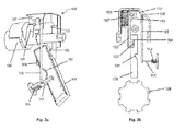
- Fig. 2a and 2b show a schematic representation of the steering wheel lock 100 in an unlocked state. A repeated description of identical features of the preceding figures will be omitted.
- the locking pin 101 is in an unlocking position, in which the locking pin 101, the recess of the locking ring 129 releases.
- the lock cylinder 109 is in this state in a position in which the actuator 110 engages the link 119 of the slider 103 and has transferred this against the force of the elastic member 107 in the unlocked position. Due to the frictional engagement of the slider 103 in the locking pin 101 of the locking pin 101 is transferred together with the slider 103 in the unlocked position.
- the locking pin 101 on the engagement 102 which with a Projection 104 of the slider 103 cooperates.
- the locking pin 101 and slider 103 are slidably formed along the contact surface between the engagement 102 and projection 104 and the contact surface is formed orthogonal to a locking direction of the locking pin 101 and parallel to a rotational axis of the locking rim 129. This makes it possible to convert the direction of movement of the slider 103 in the angled direction of movement of the locking pin 101 and vice versa.
- Fig. 3a and 3b show a schematic representation of the steering wheel lock 100 with locked locking pin 101. A repeated description of identical features of the preceding figures will be omitted.
- the locking pin 101 is in the locking position, wherein this engages in a recess of the locking ring 129.
- the triggering element 115 which is in engagement with the securing element 115, is lifted by relaxation of the elastic element 107, as a result of which the locking element 111 is released and transferred into the blocking position by relaxation of the second elastic element 113.
- a front part of the locking element 111 engages in the laterally locking pin 101 arranged on the locking recess 131 and locks it in the locked position.
- the locking recess 131 in this case has the stepped structure in order to secure the locking pin 101, even if the locking element 111 can not fully engage in the locking recess 131, because the locking pin 101, due to a randomly blocking a recess of the locking ring 129 tooth not in a Recess of the locking ring 129 can engage.
- the locking member 111 may not fully engage with the lock recess 131, it is held by the step-like structure at the lower portion of the lock recess 131.
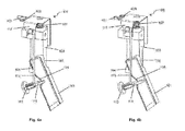
- Fig. 4a and 4b show a schematic representation of an embodiment of a steering wheel lock 100. A repeated description of identical features of the preceding figures is omitted.
- the trigger element 117 in this case has a recess 403 and the housing cover 105 has a locking pin 401.
- the recess 403 and the locking pin 401 are slightly offset in the assembled state of the steering wheel lock 100 and can not interlock in this state.
- the housing cover 105 only slightly, for example by forcibly opening or removing the housing cover 105, relative to the Trigger element 117 is moved, get the recess 403 and the locking pin 401 by relaxing the elastic member 107 with each other.
- the locking element 111 is released by the securing element and the second elastic element 113 transfers the locking element 111 in the locked position.
- Fig. 5 shows a schematic representation of another embodiment of a steering wheel lock 100.
- the triggering element 117 and the securing element 115 are formed in this embodiment by a one-piece molding 501.
- the triggering element 117 may be formed as a sheet metal bracket, wherein an extended arm of the sheet metal bracket is formed as a securing element 115.
- the triggering element 117 could also fulfill the task of covering an inner part of the steering wheel lock 100 and in particular the elastic element 107, wherein a substantially complementary design of the triggering element 117 can also be realized. This additionally improves the protective function of the inner parts and in particular of the elastic element 107.
- a space can be saved in the steering wheel lock 100, whereby the steering wheel lock 100 can be made particularly compact.
- Fig. 6a and 6b show a section of a schematic cross-sectional view of another embodiment of the steering wheel lock 100. A repeated description of identical features of the preceding figures will be omitted.
- the triggering element 117 in this case has a cylindrical recess 403, in the center of which a recess pin 601 is arranged.
- the housing cover 105 has the locking pin 401, which is aligned in the mounted state of the steering wheel lock 100 with the recess pin 601 front side and stands up on this.
- the housing cover 105 is displaced only slightly, for example by opening or removing the housing cover 105, relative to the trigger member 117, the locking pin 401 by relaxing the elastic member 107 in the cylindrical recess 403 of the trigger member 117, whereby the locking member 111 by the Fuse element 115 is released and the second elastic element 113, the locking element 111 transferred to the locked position. It is particularly advantageous in this embodiment that a displacement of the Housing cover 105, relative to the trigger member 117, in each direction for releasing the locking element 111 leads.
Landscapes
- Engineering & Computer Science (AREA)
- Mechanical Engineering (AREA)
- Lock And Its Accessories (AREA)
- Steering-Linkage Mechanisms And Four-Wheel Steering (AREA)
Applications Claiming Priority (1)
| Application Number | Priority Date | Filing Date | Title |
|---|---|---|---|
| DE102014112816.8A DE102014112816A1 (de) | 2014-09-05 | 2014-09-05 | Lenkradverriegelung |
Publications (3)
| Publication Number | Publication Date |
|---|---|
| EP2993090A1 true EP2993090A1 (fr) | 2016-03-09 |
| EP2993090B1 EP2993090B1 (fr) | 2017-05-24 |
| EP2993090B2 EP2993090B2 (fr) | 2020-08-12 |
Family
ID=53610792
Family Applications (1)
| Application Number | Title | Priority Date | Filing Date |
|---|---|---|---|
| EP15176434.7A Not-in-force EP2993090B2 (fr) | 2014-09-05 | 2015-07-13 | Verrouillage de volant de direction |
Country Status (3)
| Country | Link |
|---|---|
| EP (1) | EP2993090B2 (fr) |
| CN (1) | CN105398418B (fr) |
| DE (1) | DE102014112816A1 (fr) |
Cited By (2)
| Publication number | Priority date | Publication date | Assignee | Title |
|---|---|---|---|---|
| EP3296164A1 (fr) * | 2016-09-19 | 2018-03-21 | HUF Hülsbeck & Fürst GmbH & Co. KG | Dispositif sécurisé de fermeture d'un composant essentiellement fonctionnel du véhicule automobile |
| EP3434534A1 (fr) * | 2017-07-26 | 2019-01-30 | HUF Hülsbeck & Fürst GmbH & Co. KG | Dispositif de blocage destiné à bloquer un composant essentiel au fonctionnement d'un véhicule automobile et procédé de fixation d'une goupille de blocage d'un dispositif de blocage |
Families Citing this family (2)
| Publication number | Priority date | Publication date | Assignee | Title |
|---|---|---|---|---|
| CN110606125B (zh) * | 2019-07-09 | 2020-10-16 | 合肥工业大学 | 方向盘位置校验系统及校验方法 |
| DE102019125189A1 (de) * | 2019-09-19 | 2021-03-25 | Huf Hülsbeck & Fürst Gmbh & Co. Kg | Verriegelungsvorrichtung für ein funktionswesentliches Bauteil, Funktionseinheit für ein Fahrzeug sowie Verfahren zum zerstörungsfreien Abstützen einer Bewegung eines funktionswesentlichen Bauteils |
Citations (7)
| Publication number | Priority date | Publication date | Assignee | Title |
|---|---|---|---|---|
| EP0071803A1 (fr) | 1981-08-08 | 1983-02-16 | Neiman S.A. | Serrure de direction pour véhicule |
| JP2004314965A (ja) * | 2004-07-08 | 2004-11-11 | Tokai Rika Co Ltd | ステアリングロック装置 |
| EP2090478A1 (fr) * | 2006-11-10 | 2009-08-19 | Alpha Corporation | Dispositif antivol sur la direction |
| DE102008031217A1 (de) * | 2008-07-03 | 2010-01-07 | Huf Hülsbeck & Fürst Gmbh & Co. Kg | Sperrvorrichtung mit einem Sperrglied zur Sperrung eines funktionswesentlichen Bauteils |
| EP2275313A1 (fr) * | 2009-07-15 | 2011-01-19 | Huf Hülsbeck & Fürst GmbH & Co. KG | Dispositif de blocage destiné au blocage d'un composant essentiellement fonctionnel d'un véhicule automobile, notamment pour le blocage d'un arbre de direction de véhicule automobile |
| EP2277749A1 (fr) * | 2009-07-24 | 2011-01-26 | Huf Hülsbeck & Fürst GmbH & Co. KG | Dispositif de fermeture d'un composant essentiellement fonctionnel de véhicule automobile |
| EP2420416A2 (fr) * | 2010-08-19 | 2012-02-22 | Huf Hülsbeck & Fürst GmbH & Co. KG | Dispositif de logement d'un élément de blocage mobile |
Family Cites Families (20)
| Publication number | Priority date | Publication date | Assignee | Title |
|---|---|---|---|---|
| DE19614436C1 (de) | 1996-04-12 | 1997-06-12 | Ymos Ag Ind Produkte | Kraftfahrzeug-Lenkradschloß |
| JPH11310104A (ja) | 1998-04-27 | 1999-11-09 | Toyota Motor Corp | ステアリングロック装置 |
| DE10041984B4 (de) | 2000-08-26 | 2006-02-23 | Valeo Sicherheitssysteme Gmbh | Vorrichtung zur Verriegelung der Lenkspindel eines Fahrzeuges |
| GB2376044B (en) * | 2001-06-01 | 2005-05-25 | Tokai Rika Co Ltd | Steering wheel locking device |
| DE10247802B3 (de) | 2002-10-14 | 2004-02-05 | Huf Hülsbeck & Fürst Gmbh & Co. Kg | Vorrichtung zum Sperren der Lenkspindel eines Kraftfahrzeugs |
| DE10247803B3 (de) | 2002-10-14 | 2004-01-29 | Huf Hülsbeck & Fürst Gmbh & Co. Kg | Vorrichtung zum Sperren der Lenkspindel eines Kraftfahrzeugs |
| DE10300473A1 (de) * | 2003-01-09 | 2004-07-22 | Valeo Sicherheitssysteme Gmbh | Vorrichtung zur Verriegelung der Lenkspindel eines Kraftfahrzeuges |
| JP4038132B2 (ja) | 2003-01-31 | 2008-01-23 | 株式会社東海理化電機製作所 | 電動ステアリングロック装置 |
| DE10320138B3 (de) * | 2003-05-06 | 2005-01-13 | Huf Hülsbeck & Fürst Gmbh & Co. Kg | Vorrichtung zum Sperren der Lenkspindel eines Kraftfahrzeugs |
| ITTO20040082A1 (it) * | 2004-02-13 | 2004-05-13 | Trw Automotive Italia S P A | Dispositivo bloccasterzo per un gruppo di sterzatura di un veicolo |
| US7140213B2 (en) | 2004-02-21 | 2006-11-28 | Strattec Security Corporation | Steering column lock apparatus and method |
| DE102004031238B4 (de) | 2004-06-29 | 2015-03-12 | Huf Hülsbeck & Fürst Gmbh & Co. Kg | Vorrichtung zum Verriegeln und/oder Entriegeln eines Lenkrades eines Kraftfahrzeugs |
| DE102005030727B4 (de) | 2005-07-01 | 2015-02-26 | Huf Hülsbeck & Fürst GmbH & Co KG | Vorrichtung zum Verriegeln der Lenksäule in einem Fahrzeug |
| JP4980853B2 (ja) | 2006-11-10 | 2012-07-18 | 株式会社アルファ | 電動ステアリングロック装置 |
| DE102007034481A1 (de) | 2007-07-20 | 2009-01-22 | Huf Hülsbeck & Fürst Gmbh & Co. Kg | Verriegelungsvorrichtung mit Arretierungsteil |
| JP4881843B2 (ja) | 2007-11-30 | 2012-02-22 | 株式会社アルファ | ステアリングロック装置 |
| DE102007059713A1 (de) * | 2007-12-10 | 2009-06-18 | Huf Hülsbeck & Fürst Gmbh & Co. Kg | Vorrichtung zur Ansteuerung eines Sperrgliedes |
| JP4629751B2 (ja) | 2008-04-09 | 2011-02-09 | 株式会社ユーシン | ステアリングロック装置 |
| FR2964350A1 (fr) | 2010-09-02 | 2012-03-09 | Valeo Securite Habitacle | Antivol de direction pour vehicule automobile |
| FR2984823B1 (fr) | 2011-12-21 | 2016-01-01 | Valeo Securite Habitacle | Dispositif antivol pour colonne de direction de vehicule automobile |
-
2014
- 2014-09-05 DE DE102014112816.8A patent/DE102014112816A1/de not_active Withdrawn
-
2015
- 2015-07-13 EP EP15176434.7A patent/EP2993090B2/fr not_active Not-in-force
- 2015-09-01 CN CN201510552559.XA patent/CN105398418B/zh not_active Expired - Fee Related
Patent Citations (7)
| Publication number | Priority date | Publication date | Assignee | Title |
|---|---|---|---|---|
| EP0071803A1 (fr) | 1981-08-08 | 1983-02-16 | Neiman S.A. | Serrure de direction pour véhicule |
| JP2004314965A (ja) * | 2004-07-08 | 2004-11-11 | Tokai Rika Co Ltd | ステアリングロック装置 |
| EP2090478A1 (fr) * | 2006-11-10 | 2009-08-19 | Alpha Corporation | Dispositif antivol sur la direction |
| DE102008031217A1 (de) * | 2008-07-03 | 2010-01-07 | Huf Hülsbeck & Fürst Gmbh & Co. Kg | Sperrvorrichtung mit einem Sperrglied zur Sperrung eines funktionswesentlichen Bauteils |
| EP2275313A1 (fr) * | 2009-07-15 | 2011-01-19 | Huf Hülsbeck & Fürst GmbH & Co. KG | Dispositif de blocage destiné au blocage d'un composant essentiellement fonctionnel d'un véhicule automobile, notamment pour le blocage d'un arbre de direction de véhicule automobile |
| EP2277749A1 (fr) * | 2009-07-24 | 2011-01-26 | Huf Hülsbeck & Fürst GmbH & Co. KG | Dispositif de fermeture d'un composant essentiellement fonctionnel de véhicule automobile |
| EP2420416A2 (fr) * | 2010-08-19 | 2012-02-22 | Huf Hülsbeck & Fürst GmbH & Co. KG | Dispositif de logement d'un élément de blocage mobile |
Cited By (3)
| Publication number | Priority date | Publication date | Assignee | Title |
|---|---|---|---|---|
| EP3296164A1 (fr) * | 2016-09-19 | 2018-03-21 | HUF Hülsbeck & Fürst GmbH & Co. KG | Dispositif sécurisé de fermeture d'un composant essentiellement fonctionnel du véhicule automobile |
| EP3296163A1 (fr) * | 2016-09-19 | 2018-03-21 | HUF Hülsbeck & Fürst GmbH & Co. KG | Dispositif sécurisé de fermeture d'un composant essentiellement fonctionnel du véhicule automobile |
| EP3434534A1 (fr) * | 2017-07-26 | 2019-01-30 | HUF Hülsbeck & Fürst GmbH & Co. KG | Dispositif de blocage destiné à bloquer un composant essentiel au fonctionnement d'un véhicule automobile et procédé de fixation d'une goupille de blocage d'un dispositif de blocage |
Also Published As
| Publication number | Publication date |
|---|---|
| CN105398418A (zh) | 2016-03-16 |
| DE102014112816A1 (de) | 2016-03-10 |
| EP2993090B1 (fr) | 2017-05-24 |
| CN105398418B (zh) | 2019-07-05 |
| EP2993090B2 (fr) | 2020-08-12 |
Similar Documents
| Publication | Publication Date | Title |
|---|---|---|
| DE102008034460A1 (de) | Türaußengriff, insbesondere für Fahrzeuge | |
| EP2828456B1 (fr) | Verrouillage de portière de véhicule automobile | |
| EP2993090B1 (fr) | Verrouillage de volant de direction | |
| DE102018116313A1 (de) | Schloss für ein kraftfahrzeug | |
| WO2014032641A2 (fr) | Portière pour véhicule automobile | |
| DE102013011803A1 (de) | Verriegelungsvorrichtung | |
| DE102013114625A1 (de) | Nockenwellenverstellvorrichtung, Verbrennungsmotor sowie Montageverfahren | |
| EP3262258B1 (fr) | Fermeture de porte de véhicule automobile | |
| DE102014107244B4 (de) | Lenkradschlosseinrichtung | |
| DE102012111881A1 (de) | Motorisch betreibbares Standflügelschloss mit Riegel- und Fallenauswerfer | |
| DE102009016812A1 (de) | Türverschluss für ein thermisches Gar- und/oder Backgerät | |
| EP3117057B1 (fr) | Système de fermeture de portière de véhicule automobile | |
| DE102016121735A1 (de) | Schloss für ein Kraftfahrzeug | |
| DE4339654C3 (de) | Kraftfahrzeugtürverschluß | |
| DE102018116325A1 (de) | Schloss für ein Kraftfahrzeug | |
| DE202013011809U1 (de) | Lenkradschloss für eine Lenksäule für ein Kraftfahrzeug | |
| WO2018082924A1 (fr) | Unité de fermeture pour un véhicule automobile | |
| DE102017121736A1 (de) | Gesicherte Vorrichtung zum Sperren eines funktionswesentlichen Bauteils eines Kraftfahrzeugs | |
| EP1657385B1 (fr) | Actionneur pour véhicule à moteur | |
| DE102010034498A1 (de) | Schocksicherer Schnellverschluss für einen Endbeschlag eines Sicherheitsgurtes | |
| EP0831198A1 (fr) | Cadenas | |
| DE102020106126A1 (de) | Kraftfahrzeugschloss | |
| DE102019124646B4 (de) | Verriegelungseinrichtung | |
| DE2047702C3 (de) | Diebstahlsicherung für Kraftfahrzeuge | |
| EP3434534B1 (fr) | Dispositif de blocage destiné à bloquer un composant essentiel au fonctionnement d'un véhicule automobile et procédé de fixation d'une goupille de blocage d'un dispositif de blocage |
Legal Events
| Date | Code | Title | Description |
|---|---|---|---|
| PUAI | Public reference made under article 153(3) epc to a published international application that has entered the european phase |
Free format text: ORIGINAL CODE: 0009012 |
|
| AK | Designated contracting states |
Kind code of ref document: A1 Designated state(s): AL AT BE BG CH CY CZ DE DK EE ES FI FR GB GR HR HU IE IS IT LI LT LU LV MC MK MT NL NO PL PT RO RS SE SI SK SM TR |
|
| AX | Request for extension of the european patent |
Extension state: BA ME |
|
| 17P | Request for examination filed |
Effective date: 20160330 |
|
| RBV | Designated contracting states (corrected) |
Designated state(s): AL AT BE BG CH CY CZ DE DK EE ES FI FR GB GR HR HU IE IS IT LI LT LU LV MC MK MT NL NO PL PT RO RS SE SI SK SM TR |
|
| GRAP | Despatch of communication of intention to grant a patent |
Free format text: ORIGINAL CODE: EPIDOSNIGR1 |
|
| STAA | Information on the status of an ep patent application or granted ep patent |
Free format text: STATUS: GRANT OF PATENT IS INTENDED |
|
| GRAS | Grant fee paid |
Free format text: ORIGINAL CODE: EPIDOSNIGR3 |
|
| INTG | Intention to grant announced |
Effective date: 20170316 |
|
| GRAA | (expected) grant |
Free format text: ORIGINAL CODE: 0009210 |
|
| STAA | Information on the status of an ep patent application or granted ep patent |
Free format text: STATUS: THE PATENT HAS BEEN GRANTED |
|
| AK | Designated contracting states |
Kind code of ref document: B1 Designated state(s): AL AT BE BG CH CY CZ DE DK EE ES FI FR GB GR HR HU IE IS IT LI LT LU LV MC MK MT NL NO PL PT RO RS SE SI SK SM TR |
|
| REG | Reference to a national code |
Ref country code: GB Ref legal event code: FG4D Free format text: NOT ENGLISH |
|
| REG | Reference to a national code |
Ref country code: CH Ref legal event code: EP |
|
| REG | Reference to a national code |
Ref country code: IE Ref legal event code: FG4D Free format text: LANGUAGE OF EP DOCUMENT: GERMAN |
|
| REG | Reference to a national code |
Ref country code: AT Ref legal event code: REF Ref document number: 895868 Country of ref document: AT Kind code of ref document: T Effective date: 20170615 |
|
| REG | Reference to a national code |
Ref country code: DE Ref legal event code: R096 Ref document number: 502015001109 Country of ref document: DE |
|
| REG | Reference to a national code |
Ref country code: FR Ref legal event code: PLFP Year of fee payment: 3 |
|
| REG | Reference to a national code |
Ref country code: NL Ref legal event code: MP Effective date: 20170524 |
|
| REG | Reference to a national code |
Ref country code: LT Ref legal event code: MG4D |
|
| PG25 | Lapsed in a contracting state [announced via postgrant information from national office to epo] |
Ref country code: GR Free format text: LAPSE BECAUSE OF FAILURE TO SUBMIT A TRANSLATION OF THE DESCRIPTION OR TO PAY THE FEE WITHIN THE PRESCRIBED TIME-LIMIT Effective date: 20170825 Ref country code: NO Free format text: LAPSE BECAUSE OF FAILURE TO SUBMIT A TRANSLATION OF THE DESCRIPTION OR TO PAY THE FEE WITHIN THE PRESCRIBED TIME-LIMIT Effective date: 20170824 Ref country code: LT Free format text: LAPSE BECAUSE OF FAILURE TO SUBMIT A TRANSLATION OF THE DESCRIPTION OR TO PAY THE FEE WITHIN THE PRESCRIBED TIME-LIMIT Effective date: 20170524 Ref country code: FI Free format text: LAPSE BECAUSE OF FAILURE TO SUBMIT A TRANSLATION OF THE DESCRIPTION OR TO PAY THE FEE WITHIN THE PRESCRIBED TIME-LIMIT Effective date: 20170524 Ref country code: HR Free format text: LAPSE BECAUSE OF FAILURE TO SUBMIT A TRANSLATION OF THE DESCRIPTION OR TO PAY THE FEE WITHIN THE PRESCRIBED TIME-LIMIT Effective date: 20170524 Ref country code: ES Free format text: LAPSE BECAUSE OF FAILURE TO SUBMIT A TRANSLATION OF THE DESCRIPTION OR TO PAY THE FEE WITHIN THE PRESCRIBED TIME-LIMIT Effective date: 20170524 |
|
| PG25 | Lapsed in a contracting state [announced via postgrant information from national office to epo] |
Ref country code: IS Free format text: LAPSE BECAUSE OF FAILURE TO SUBMIT A TRANSLATION OF THE DESCRIPTION OR TO PAY THE FEE WITHIN THE PRESCRIBED TIME-LIMIT Effective date: 20170924 Ref country code: SE Free format text: LAPSE BECAUSE OF FAILURE TO SUBMIT A TRANSLATION OF THE DESCRIPTION OR TO PAY THE FEE WITHIN THE PRESCRIBED TIME-LIMIT Effective date: 20170524 Ref country code: LV Free format text: LAPSE BECAUSE OF FAILURE TO SUBMIT A TRANSLATION OF THE DESCRIPTION OR TO PAY THE FEE WITHIN THE PRESCRIBED TIME-LIMIT Effective date: 20170524 Ref country code: RS Free format text: LAPSE BECAUSE OF FAILURE TO SUBMIT A TRANSLATION OF THE DESCRIPTION OR TO PAY THE FEE WITHIN THE PRESCRIBED TIME-LIMIT Effective date: 20170524 Ref country code: BG Free format text: LAPSE BECAUSE OF FAILURE TO SUBMIT A TRANSLATION OF THE DESCRIPTION OR TO PAY THE FEE WITHIN THE PRESCRIBED TIME-LIMIT Effective date: 20170824 Ref country code: NL Free format text: LAPSE BECAUSE OF FAILURE TO SUBMIT A TRANSLATION OF THE DESCRIPTION OR TO PAY THE FEE WITHIN THE PRESCRIBED TIME-LIMIT Effective date: 20170524 |
|
| PG25 | Lapsed in a contracting state [announced via postgrant information from national office to epo] |
Ref country code: DK Free format text: LAPSE BECAUSE OF FAILURE TO SUBMIT A TRANSLATION OF THE DESCRIPTION OR TO PAY THE FEE WITHIN THE PRESCRIBED TIME-LIMIT Effective date: 20170524 Ref country code: EE Free format text: LAPSE BECAUSE OF FAILURE TO SUBMIT A TRANSLATION OF THE DESCRIPTION OR TO PAY THE FEE WITHIN THE PRESCRIBED TIME-LIMIT Effective date: 20170524 Ref country code: CZ Free format text: LAPSE BECAUSE OF FAILURE TO SUBMIT A TRANSLATION OF THE DESCRIPTION OR TO PAY THE FEE WITHIN THE PRESCRIBED TIME-LIMIT Effective date: 20170524 Ref country code: SK Free format text: LAPSE BECAUSE OF FAILURE TO SUBMIT A TRANSLATION OF THE DESCRIPTION OR TO PAY THE FEE WITHIN THE PRESCRIBED TIME-LIMIT Effective date: 20170524 Ref country code: RO Free format text: LAPSE BECAUSE OF FAILURE TO SUBMIT A TRANSLATION OF THE DESCRIPTION OR TO PAY THE FEE WITHIN THE PRESCRIBED TIME-LIMIT Effective date: 20170524 |
|
| REG | Reference to a national code |
Ref country code: DE Ref legal event code: R026 Ref document number: 502015001109 Country of ref document: DE |
|
| PG25 | Lapsed in a contracting state [announced via postgrant information from national office to epo] |
Ref country code: IT Free format text: LAPSE BECAUSE OF FAILURE TO SUBMIT A TRANSLATION OF THE DESCRIPTION OR TO PAY THE FEE WITHIN THE PRESCRIBED TIME-LIMIT Effective date: 20170524 Ref country code: PL Free format text: LAPSE BECAUSE OF FAILURE TO SUBMIT A TRANSLATION OF THE DESCRIPTION OR TO PAY THE FEE WITHIN THE PRESCRIBED TIME-LIMIT Effective date: 20170524 Ref country code: SM Free format text: LAPSE BECAUSE OF FAILURE TO SUBMIT A TRANSLATION OF THE DESCRIPTION OR TO PAY THE FEE WITHIN THE PRESCRIBED TIME-LIMIT Effective date: 20170524 |
|
| PLBI | Opposition filed |
Free format text: ORIGINAL CODE: 0009260 |
|
| PLAX | Notice of opposition and request to file observation + time limit sent |
Free format text: ORIGINAL CODE: EPIDOSNOBS2 |
|
| 26 | Opposition filed |
Opponent name: U-SHIN DEUTSCHLAND ZUGANGSSYSTEME Effective date: 20180223 |
|
| REG | Reference to a national code |
Ref country code: IE Ref legal event code: MM4A |
|
| PG25 | Lapsed in a contracting state [announced via postgrant information from national office to epo] |
Ref country code: IE Free format text: LAPSE BECAUSE OF NON-PAYMENT OF DUE FEES Effective date: 20170713 |
|
| REG | Reference to a national code |
Ref country code: BE Ref legal event code: MM Effective date: 20170731 |
|
| PG25 | Lapsed in a contracting state [announced via postgrant information from national office to epo] |
Ref country code: SI Free format text: LAPSE BECAUSE OF FAILURE TO SUBMIT A TRANSLATION OF THE DESCRIPTION OR TO PAY THE FEE WITHIN THE PRESCRIBED TIME-LIMIT Effective date: 20170524 |
|
| PG25 | Lapsed in a contracting state [announced via postgrant information from national office to epo] |
Ref country code: LU Free format text: LAPSE BECAUSE OF NON-PAYMENT OF DUE FEES Effective date: 20170713 |
|
| PLBB | Reply of patent proprietor to notice(s) of opposition received |
Free format text: ORIGINAL CODE: EPIDOSNOBS3 |
|
| REG | Reference to a national code |
Ref country code: FR Ref legal event code: PLFP Year of fee payment: 4 |
|
| PG25 | Lapsed in a contracting state [announced via postgrant information from national office to epo] |
Ref country code: BE Free format text: LAPSE BECAUSE OF NON-PAYMENT OF DUE FEES Effective date: 20170731 |
|
| PG25 | Lapsed in a contracting state [announced via postgrant information from national office to epo] |
Ref country code: MT Free format text: LAPSE BECAUSE OF FAILURE TO SUBMIT A TRANSLATION OF THE DESCRIPTION OR TO PAY THE FEE WITHIN THE PRESCRIBED TIME-LIMIT Effective date: 20170524 |
|
| REG | Reference to a national code |
Ref country code: CH Ref legal event code: PL |
|
| PG25 | Lapsed in a contracting state [announced via postgrant information from national office to epo] |
Ref country code: CH Free format text: LAPSE BECAUSE OF NON-PAYMENT OF DUE FEES Effective date: 20180731 Ref country code: LI Free format text: LAPSE BECAUSE OF NON-PAYMENT OF DUE FEES Effective date: 20180731 |
|
| PG25 | Lapsed in a contracting state [announced via postgrant information from national office to epo] |
Ref country code: MC Free format text: LAPSE BECAUSE OF FAILURE TO SUBMIT A TRANSLATION OF THE DESCRIPTION OR TO PAY THE FEE WITHIN THE PRESCRIBED TIME-LIMIT Effective date: 20170524 Ref country code: HU Free format text: LAPSE BECAUSE OF FAILURE TO SUBMIT A TRANSLATION OF THE DESCRIPTION OR TO PAY THE FEE WITHIN THE PRESCRIBED TIME-LIMIT; INVALID AB INITIO Effective date: 20150713 |
|
| PLAB | Opposition data, opponent's data or that of the opponent's representative modified |
Free format text: ORIGINAL CODE: 0009299OPPO |
|
| R26 | Opposition filed (corrected) |
Opponent name: U-SHIN DEUTSCHLAND ZUGANGSSYSTEME Effective date: 20180223 |
|
| PG25 | Lapsed in a contracting state [announced via postgrant information from national office to epo] |
Ref country code: CY Free format text: LAPSE BECAUSE OF FAILURE TO SUBMIT A TRANSLATION OF THE DESCRIPTION OR TO PAY THE FEE WITHIN THE PRESCRIBED TIME-LIMIT Effective date: 20170524 |
|
| PG25 | Lapsed in a contracting state [announced via postgrant information from national office to epo] |
Ref country code: MK Free format text: LAPSE BECAUSE OF FAILURE TO SUBMIT A TRANSLATION OF THE DESCRIPTION OR TO PAY THE FEE WITHIN THE PRESCRIBED TIME-LIMIT Effective date: 20170524 |
|
| APBM | Appeal reference recorded |
Free format text: ORIGINAL CODE: EPIDOSNREFNO |
|
| APBP | Date of receipt of notice of appeal recorded |
Free format text: ORIGINAL CODE: EPIDOSNNOA2O |
|
| APAH | Appeal reference modified |
Free format text: ORIGINAL CODE: EPIDOSCREFNO |
|
| APBU | Appeal procedure closed |
Free format text: ORIGINAL CODE: EPIDOSNNOA9O |
|
| GBPC | Gb: european patent ceased through non-payment of renewal fee |
Effective date: 20190713 |
|
| PG25 | Lapsed in a contracting state [announced via postgrant information from national office to epo] |
Ref country code: TR Free format text: LAPSE BECAUSE OF FAILURE TO SUBMIT A TRANSLATION OF THE DESCRIPTION OR TO PAY THE FEE WITHIN THE PRESCRIBED TIME-LIMIT Effective date: 20170524 |
|
| PG25 | Lapsed in a contracting state [announced via postgrant information from national office to epo] |
Ref country code: GB Free format text: LAPSE BECAUSE OF NON-PAYMENT OF DUE FEES Effective date: 20190713 |
|
| PG25 | Lapsed in a contracting state [announced via postgrant information from national office to epo] |
Ref country code: PT Free format text: LAPSE BECAUSE OF FAILURE TO SUBMIT A TRANSLATION OF THE DESCRIPTION OR TO PAY THE FEE WITHIN THE PRESCRIBED TIME-LIMIT Effective date: 20170524 |
|
| PUAH | Patent maintained in amended form |
Free format text: ORIGINAL CODE: 0009272 |
|
| STAA | Information on the status of an ep patent application or granted ep patent |
Free format text: STATUS: PATENT MAINTAINED AS AMENDED |
|
| PG25 | Lapsed in a contracting state [announced via postgrant information from national office to epo] |
Ref country code: AL Free format text: LAPSE BECAUSE OF FAILURE TO SUBMIT A TRANSLATION OF THE DESCRIPTION OR TO PAY THE FEE WITHIN THE PRESCRIBED TIME-LIMIT Effective date: 20170524 |
|
| 27A | Patent maintained in amended form |
Effective date: 20200812 |
|
| AK | Designated contracting states |
Kind code of ref document: B2 Designated state(s): AL AT BE BG CH CY CZ DE DK EE ES FI FR GB GR HR HU IE IS IT LI LT LU LV MC MK MT NL NO PL PT RO RS SE SI SK SM TR |
|
| REG | Reference to a national code |
Ref country code: DE Ref legal event code: R102 Ref document number: 502015001109 Country of ref document: DE |
|
| REG | Reference to a national code |
Ref country code: AT Ref legal event code: MM01 Ref document number: 895868 Country of ref document: AT Kind code of ref document: T Effective date: 20200713 |
|
| PG25 | Lapsed in a contracting state [announced via postgrant information from national office to epo] |
Ref country code: AT Free format text: LAPSE BECAUSE OF NON-PAYMENT OF DUE FEES Effective date: 20200713 |
|
| PGFP | Annual fee paid to national office [announced via postgrant information from national office to epo] |
Ref country code: FR Payment date: 20210721 Year of fee payment: 7 |
|
| PGFP | Annual fee paid to national office [announced via postgrant information from national office to epo] |
Ref country code: DE Payment date: 20210721 Year of fee payment: 7 |
|
| REG | Reference to a national code |
Ref country code: DE Ref legal event code: R119 Ref document number: 502015001109 Country of ref document: DE |
|
| PG25 | Lapsed in a contracting state [announced via postgrant information from national office to epo] |
Ref country code: FR Free format text: LAPSE BECAUSE OF NON-PAYMENT OF DUE FEES Effective date: 20220731 |
|
| PG25 | Lapsed in a contracting state [announced via postgrant information from national office to epo] |
Ref country code: DE Free format text: LAPSE BECAUSE OF NON-PAYMENT OF DUE FEES Effective date: 20230201 |