EP2992044B1 - Tuyau en polyoléfine - Google Patents
Tuyau en polyoléfine Download PDFInfo
- Publication number
- EP2992044B1 EP2992044B1 EP14721288.0A EP14721288A EP2992044B1 EP 2992044 B1 EP2992044 B1 EP 2992044B1 EP 14721288 A EP14721288 A EP 14721288A EP 2992044 B1 EP2992044 B1 EP 2992044B1
- Authority
- EP
- European Patent Office
- Prior art keywords
- pipe
- alkyl
- weight
- photoinitiator
- scavenger
- Prior art date
- Legal status (The legal status is an assumption and is not a legal conclusion. Google has not performed a legal analysis and makes no representation as to the accuracy of the status listed.)
- Active
Links
- 229920000098 polyolefin Polymers 0.000 title claims description 53
- -1 -OH Chemical group 0.000 claims description 92
- 238000000034 method Methods 0.000 claims description 92
- 239000003795 chemical substances by application Substances 0.000 claims description 77
- 229920000642 polymer Polymers 0.000 claims description 73
- 238000004132 cross linking Methods 0.000 claims description 65
- 239000012948 isocyanate Substances 0.000 claims description 63
- 239000004698 Polyethylene Substances 0.000 claims description 62
- 229920000573 polyethylene Polymers 0.000 claims description 62
- 239000000203 mixture Substances 0.000 claims description 59
- 239000003963 antioxidant agent Substances 0.000 claims description 54
- UHOVQNZJYSORNB-UHFFFAOYSA-N Benzene Chemical compound C1=CC=CC=C1 UHOVQNZJYSORNB-UHFFFAOYSA-N 0.000 claims description 51
- 150000001875 compounds Chemical class 0.000 claims description 51
- 125000000217 alkyl group Chemical group 0.000 claims description 43
- 230000003078 antioxidant effect Effects 0.000 claims description 40
- 150000002513 isocyanates Chemical class 0.000 claims description 39
- 239000000463 material Substances 0.000 claims description 39
- 239000002516 radical scavenger Substances 0.000 claims description 39
- 238000001125 extrusion Methods 0.000 claims description 38
- NPFYZDNDJHZQKY-UHFFFAOYSA-N 4-Hydroxybenzophenone Chemical compound C1=CC(O)=CC=C1C(=O)C1=CC=CC=C1 NPFYZDNDJHZQKY-UHFFFAOYSA-N 0.000 claims description 37
- 239000002105 nanoparticle Substances 0.000 claims description 29
- 229920002857 polybutadiene Polymers 0.000 claims description 29
- RWCCWEUUXYIKHB-UHFFFAOYSA-N benzophenone Chemical compound C=1C=CC=CC=1C(=O)C1=CC=CC=C1 RWCCWEUUXYIKHB-UHFFFAOYSA-N 0.000 claims description 27
- PNEYBMLMFCGWSK-UHFFFAOYSA-N Alumina Chemical compound [O-2].[O-2].[O-2].[Al+3].[Al+3] PNEYBMLMFCGWSK-UHFFFAOYSA-N 0.000 claims description 26
- 239000005062 Polybutadiene Substances 0.000 claims description 25
- XLYOFNOQVPJJNP-UHFFFAOYSA-N water Substances O XLYOFNOQVPJJNP-UHFFFAOYSA-N 0.000 claims description 24
- 239000012965 benzophenone Substances 0.000 claims description 23
- 125000004178 (C1-C4) alkyl group Chemical group 0.000 claims description 19
- QATSOLLSVDVSAL-UHFFFAOYSA-N 4-[hydroxy(phenyl)methyl]phenol Chemical compound C=1C=C(O)C=CC=1C(O)C1=CC=CC=C1 QATSOLLSVDVSAL-UHFFFAOYSA-N 0.000 claims description 17
- 239000004611 light stabiliser Substances 0.000 claims description 16
- 150000002118 epoxides Chemical class 0.000 claims description 15
- 150000001412 amines Chemical class 0.000 claims description 14
- 239000011203 carbon fibre reinforced carbon Substances 0.000 claims description 14
- 125000001475 halogen functional group Chemical group 0.000 claims description 12
- 229920001903 high density polyethylene Polymers 0.000 claims description 12
- 239000004700 high-density polyethylene Substances 0.000 claims description 12
- BJELTSYBAHKXRW-UHFFFAOYSA-N 2,4,6-triallyloxy-1,3,5-triazine Chemical compound C=CCOC1=NC(OCC=C)=NC(OCC=C)=N1 BJELTSYBAHKXRW-UHFFFAOYSA-N 0.000 claims description 10
- 239000002530 phenolic antioxidant Substances 0.000 claims description 10
- 150000001252 acrylic acid derivatives Chemical class 0.000 claims description 9
- 238000002156 mixing Methods 0.000 claims description 9
- 239000004743 Polypropylene Substances 0.000 claims description 7
- 229920001155 polypropylene Polymers 0.000 claims description 7
- 230000005855 radiation Effects 0.000 claims description 7
- 229920001730 Moisture cure polyurethane Polymers 0.000 claims description 6
- 125000004399 C1-C4 alkenyl group Chemical group 0.000 claims description 5
- QILSFLSDHQAZET-UHFFFAOYSA-N diphenylmethanol Chemical compound C=1C=CC=CC=1C(O)C1=CC=CC=C1 QILSFLSDHQAZET-UHFFFAOYSA-N 0.000 claims description 5
- NIXOWILDQLNWCW-UHFFFAOYSA-M Acrylate Chemical compound [O-]C(=O)C=C NIXOWILDQLNWCW-UHFFFAOYSA-M 0.000 claims description 4
- 125000004386 diacrylate group Chemical group 0.000 claims description 4
- 230000001678 irradiating effect Effects 0.000 claims description 4
- 229920001748 polybutylene Polymers 0.000 claims description 4
- 229920002635 polyurethane Polymers 0.000 claims description 4
- 239000004814 polyurethane Substances 0.000 claims description 4
- MLZBRARCTFICSV-UHFFFAOYSA-N 4-benzoylbenzaldehyde Chemical compound C1=CC(C=O)=CC=C1C(=O)C1=CC=CC=C1 MLZBRARCTFICSV-UHFFFAOYSA-N 0.000 claims description 3
- 239000005058 Isophorone diisocyanate Substances 0.000 claims description 3
- QYKIQEUNHZKYBP-UHFFFAOYSA-N Vinyl ether Chemical class C=COC=C QYKIQEUNHZKYBP-UHFFFAOYSA-N 0.000 claims description 3
- 229920001577 copolymer Polymers 0.000 claims description 3
- NIMLQBUJDJZYEJ-UHFFFAOYSA-N isophorone diisocyanate Chemical compound CC1(C)CC(N=C=O)CC(C)(CN=C=O)C1 NIMLQBUJDJZYEJ-UHFFFAOYSA-N 0.000 claims description 3
- 239000005057 Hexamethylene diisocyanate Substances 0.000 claims description 2
- RRAMGCGOFNQTLD-UHFFFAOYSA-N hexamethylene diisocyanate Chemical compound O=C=NCCCCCCN=C=O RRAMGCGOFNQTLD-UHFFFAOYSA-N 0.000 claims description 2
- 125000004356 hydroxy functional group Chemical group O* 0.000 claims description 2
- 239000003921 oil Substances 0.000 claims description 2
- YTKGRNLQFINUJR-UHFFFAOYSA-N 2,2-bis(acetyloxymethyl)butyl acetate Chemical compound CC(=O)OCC(CC)(COC(C)=O)COC(C)=O YTKGRNLQFINUJR-UHFFFAOYSA-N 0.000 claims 2
- 239000000155 melt Substances 0.000 claims 2
- 229920002121 Hydroxyl-terminated polybutadiene Polymers 0.000 claims 1
- 235000006708 antioxidants Nutrition 0.000 description 49
- 230000008569 process Effects 0.000 description 49
- 238000012360 testing method Methods 0.000 description 46
- 229920003020 cross-linked polyethylene Polymers 0.000 description 41
- 239000004703 cross-linked polyethylene Substances 0.000 description 41
- SSDSCDGVMJFTEQ-UHFFFAOYSA-N octadecyl 3-(3,5-ditert-butyl-4-hydroxyphenyl)propanoate Chemical compound CCCCCCCCCCCCCCCCCCOC(=O)CCC1=CC(C(C)(C)C)=C(O)C(C(C)(C)C)=C1 SSDSCDGVMJFTEQ-UHFFFAOYSA-N 0.000 description 38
- 238000009472 formulation Methods 0.000 description 34
- 239000003381 stabilizer Substances 0.000 description 32
- 239000000654 additive Substances 0.000 description 31
- 238000002386 leaching Methods 0.000 description 27
- 239000002994 raw material Substances 0.000 description 26
- 239000003651 drinking water Substances 0.000 description 24
- JLZIIHMTTRXXIN-UHFFFAOYSA-N 2-(2-hydroxy-4-methoxybenzoyl)benzoic acid Chemical compound OC1=CC(OC)=CC=C1C(=O)C1=CC=CC=C1C(O)=O JLZIIHMTTRXXIN-UHFFFAOYSA-N 0.000 description 22
- 239000006057 Non-nutritive feed additive Substances 0.000 description 21
- PGYPOBZJRVSMDS-UHFFFAOYSA-N loperamide hydrochloride Chemical compound Cl.C=1C=CC=CC=1C(C=1C=CC=CC=1)(C(=O)N(C)C)CCN(CC1)CCC1(O)C1=CC=C(Cl)C=C1 PGYPOBZJRVSMDS-UHFFFAOYSA-N 0.000 description 20
- 235000020188 drinking water Nutrition 0.000 description 19
- 239000003517 fume Substances 0.000 description 19
- KAKZBPTYRLMSJV-UHFFFAOYSA-N Butadiene Chemical compound C=CC=C KAKZBPTYRLMSJV-UHFFFAOYSA-N 0.000 description 18
- 239000000126 substance Substances 0.000 description 18
- 239000000047 product Substances 0.000 description 14
- 229920005989 resin Polymers 0.000 description 14
- 239000011347 resin Substances 0.000 description 14
- 238000003556 assay Methods 0.000 description 13
- 125000004432 carbon atom Chemical group C* 0.000 description 13
- 230000007774 longterm Effects 0.000 description 13
- 238000004519 manufacturing process Methods 0.000 description 13
- 229910052801 chlorine Inorganic materials 0.000 description 12
- 239000000460 chlorine Substances 0.000 description 12
- 125000003386 piperidinyl group Chemical group 0.000 description 11
- UPMLOUAZCHDJJD-UHFFFAOYSA-N 4,4'-Diphenylmethane Diisocyanate Chemical compound C1=CC(N=C=O)=CC=C1CC1=CC=C(N=C=O)C=C1 UPMLOUAZCHDJJD-UHFFFAOYSA-N 0.000 description 10
- 238000004458 analytical method Methods 0.000 description 10
- 238000009826 distribution Methods 0.000 description 10
- ZFSLODLOARCGLH-UHFFFAOYSA-N isocyanuric acid Chemical compound OC1=NC(O)=NC(O)=N1 ZFSLODLOARCGLH-UHFFFAOYSA-N 0.000 description 10
- 239000010410 layer Substances 0.000 description 10
- 239000011159 matrix material Substances 0.000 description 10
- 241000894007 species Species 0.000 description 10
- ZAMOUSCENKQFHK-UHFFFAOYSA-N Chlorine atom Chemical compound [Cl] ZAMOUSCENKQFHK-UHFFFAOYSA-N 0.000 description 9
- 238000013461 design Methods 0.000 description 9
- 239000012530 fluid Substances 0.000 description 9
- 238000002347 injection Methods 0.000 description 9
- 239000007924 injection Substances 0.000 description 9
- ORECYURYFJYPKY-UHFFFAOYSA-N n,n'-bis(2,2,6,6-tetramethylpiperidin-4-yl)hexane-1,6-diamine;2,4,6-trichloro-1,3,5-triazine;2,4,4-trimethylpentan-2-amine Chemical compound CC(C)(C)CC(C)(C)N.ClC1=NC(Cl)=NC(Cl)=N1.C1C(C)(C)NC(C)(C)CC1NCCCCCCNC1CC(C)(C)NC(C)(C)C1 ORECYURYFJYPKY-UHFFFAOYSA-N 0.000 description 9
- 229920003023 plastic Polymers 0.000 description 9
- 239000004033 plastic Substances 0.000 description 9
- 150000004760 silicates Chemical class 0.000 description 9
- DAKWPKUUDNSNPN-UHFFFAOYSA-N Trimethylolpropane triacrylate Chemical compound C=CC(=O)OCC(CC)(COC(=O)C=C)COC(=O)C=C DAKWPKUUDNSNPN-UHFFFAOYSA-N 0.000 description 8
- BGYHLZZASRKEJE-UHFFFAOYSA-N [3-[3-(3,5-ditert-butyl-4-hydroxyphenyl)propanoyloxy]-2,2-bis[3-(3,5-ditert-butyl-4-hydroxyphenyl)propanoyloxymethyl]propyl] 3-(3,5-ditert-butyl-4-hydroxyphenyl)propanoate Chemical compound CC(C)(C)C1=C(O)C(C(C)(C)C)=CC(CCC(=O)OCC(COC(=O)CCC=2C=C(C(O)=C(C=2)C(C)(C)C)C(C)(C)C)(COC(=O)CCC=2C=C(C(O)=C(C=2)C(C)(C)C)C(C)(C)C)COC(=O)CCC=2C=C(C(O)=C(C=2)C(C)(C)C)C(C)(C)C)=C1 BGYHLZZASRKEJE-UHFFFAOYSA-N 0.000 description 8
- 238000012545 processing Methods 0.000 description 8
- 125000001931 aliphatic group Chemical group 0.000 description 7
- 125000003342 alkenyl group Chemical group 0.000 description 7
- 238000002290 gas chromatography-mass spectrometry Methods 0.000 description 7
- 239000012802 nanoclay Substances 0.000 description 7
- 230000001590 oxidative effect Effects 0.000 description 7
- 229920006395 saturated elastomer Polymers 0.000 description 7
- 230000008901 benefit Effects 0.000 description 6
- 238000001816 cooling Methods 0.000 description 6
- 150000002148 esters Chemical class 0.000 description 6
- 239000000284 extract Substances 0.000 description 6
- 125000000325 methylidene group Chemical group [H]C([H])=* 0.000 description 6
- 229920002959 polymer blend Polymers 0.000 description 6
- 230000035882 stress Effects 0.000 description 6
- QWDQYHPOSSHSAW-UHFFFAOYSA-N 1-isocyanatooctadecane Chemical compound CCCCCCCCCCCCCCCCCCN=C=O QWDQYHPOSSHSAW-UHFFFAOYSA-N 0.000 description 5
- 235000012206 bottled water Nutrition 0.000 description 5
- 238000006243 chemical reaction Methods 0.000 description 5
- 125000000753 cycloalkyl group Chemical group 0.000 description 5
- 238000005516 engineering process Methods 0.000 description 5
- 125000000524 functional group Chemical group 0.000 description 5
- 238000010438 heat treatment Methods 0.000 description 5
- 239000007788 liquid Substances 0.000 description 5
- 239000000178 monomer Substances 0.000 description 5
- 238000010525 oxidative degradation reaction Methods 0.000 description 5
- 150000003254 radicals Chemical class 0.000 description 5
- 0 CC(C)(C1)N(*OC(*C(C)=O)=O)C(C)(C)CC1OC Chemical compound CC(C)(C1)N(*OC(*C(C)=O)=O)C(C)(C)CC1OC 0.000 description 4
- 125000003545 alkoxy group Chemical group 0.000 description 4
- 150000008366 benzophenones Chemical class 0.000 description 4
- 238000010894 electron beam technology Methods 0.000 description 4
- 125000001495 ethyl group Chemical group [H]C([H])([H])C([H])([H])* 0.000 description 4
- 239000000835 fiber Substances 0.000 description 4
- 239000000945 filler Substances 0.000 description 4
- 125000004435 hydrogen atom Chemical group [H]* 0.000 description 4
- 125000002496 methyl group Chemical group [H]C([H])([H])* 0.000 description 4
- 238000013508 migration Methods 0.000 description 4
- 230000005012 migration Effects 0.000 description 4
- 239000007800 oxidant agent Substances 0.000 description 4
- 230000003647 oxidation Effects 0.000 description 4
- 238000007254 oxidation reaction Methods 0.000 description 4
- 239000005056 polyisocyanate Substances 0.000 description 4
- 229920001228 polyisocyanate Polymers 0.000 description 4
- 230000006641 stabilisation Effects 0.000 description 4
- 229920001169 thermoplastic Polymers 0.000 description 4
- 238000009281 ultraviolet germicidal irradiation Methods 0.000 description 4
- 239000004593 Epoxy Substances 0.000 description 3
- KFZMGEQAYNKOFK-UHFFFAOYSA-N Isopropanol Chemical compound CC(C)O KFZMGEQAYNKOFK-UHFFFAOYSA-N 0.000 description 3
- CTQNGGLPUBDAKN-UHFFFAOYSA-N O-Xylene Chemical compound CC1=CC=CC=C1C CTQNGGLPUBDAKN-UHFFFAOYSA-N 0.000 description 3
- BPQQTUXANYXVAA-UHFFFAOYSA-N Orthosilicate Chemical compound [O-][Si]([O-])([O-])[O-] BPQQTUXANYXVAA-UHFFFAOYSA-N 0.000 description 3
- DNIAPMSPPWPWGF-UHFFFAOYSA-N Propylene glycol Chemical compound CC(O)CO DNIAPMSPPWPWGF-UHFFFAOYSA-N 0.000 description 3
- 230000000996 additive effect Effects 0.000 description 3
- 230000015556 catabolic process Effects 0.000 description 3
- 239000002131 composite material Substances 0.000 description 3
- 229920006037 cross link polymer Polymers 0.000 description 3
- 238000006731 degradation reaction Methods 0.000 description 3
- 238000006356 dehydrogenation reaction Methods 0.000 description 3
- 230000006870 function Effects 0.000 description 3
- 239000007789 gas Substances 0.000 description 3
- 229910052739 hydrogen Inorganic materials 0.000 description 3
- 239000001257 hydrogen Substances 0.000 description 3
- 230000006698 induction Effects 0.000 description 3
- 239000003999 initiator Substances 0.000 description 3
- 150000002978 peroxides Chemical class 0.000 description 3
- 239000002861 polymer material Substances 0.000 description 3
- 231100000935 short-term exposure limit Toxicity 0.000 description 3
- 239000002002 slurry Substances 0.000 description 3
- 239000002904 solvent Substances 0.000 description 3
- 238000007655 standard test method Methods 0.000 description 3
- DVKJHBMWWAPEIU-UHFFFAOYSA-N toluene 2,4-diisocyanate Chemical compound CC1=CC=C(N=C=O)C=C1N=C=O DVKJHBMWWAPEIU-UHFFFAOYSA-N 0.000 description 3
- 238000011144 upstream manufacturing Methods 0.000 description 3
- 239000008096 xylene Substances 0.000 description 3
- WYTZZXDRDKSJID-UHFFFAOYSA-N (3-aminopropyl)triethoxysilane Chemical compound CCO[Si](OCC)(OCC)CCCN WYTZZXDRDKSJID-UHFFFAOYSA-N 0.000 description 2
- ZGEGCLOFRBLKSE-UHFFFAOYSA-N 1-Heptene Chemical compound CCCCCC=C ZGEGCLOFRBLKSE-UHFFFAOYSA-N 0.000 description 2
- LIKMAJRDDDTEIG-UHFFFAOYSA-N 1-hexene Chemical compound CCCCC=C LIKMAJRDDDTEIG-UHFFFAOYSA-N 0.000 description 2
- KWKAKUADMBZCLK-UHFFFAOYSA-N 1-octene Chemical compound CCCCCCC=C KWKAKUADMBZCLK-UHFFFAOYSA-N 0.000 description 2
- LEJBBGNFPAFPKQ-UHFFFAOYSA-N 2-(2-prop-2-enoyloxyethoxy)ethyl prop-2-enoate Chemical compound C=CC(=O)OCCOCCOC(=O)C=C LEJBBGNFPAFPKQ-UHFFFAOYSA-N 0.000 description 2
- XFCMNSHQOZQILR-UHFFFAOYSA-N 2-[2-(2-methylprop-2-enoyloxy)ethoxy]ethyl 2-methylprop-2-enoate Chemical compound CC(=C)C(=O)OCCOCCOC(=O)C(C)=C XFCMNSHQOZQILR-UHFFFAOYSA-N 0.000 description 2
- HCLJOFJIQIJXHS-UHFFFAOYSA-N 2-[2-[2-(2-prop-2-enoyloxyethoxy)ethoxy]ethoxy]ethyl prop-2-enoate Chemical compound C=CC(=O)OCCOCCOCCOCCOC(=O)C=C HCLJOFJIQIJXHS-UHFFFAOYSA-N 0.000 description 2
- SDUZNEIVCAVWSH-UHFFFAOYSA-N 7-oxabicyclo[4.1.0]heptane-3,4-dicarboxylic acid Chemical class C1C(C(O)=O)C(C(=O)O)CC2OC21 SDUZNEIVCAVWSH-UHFFFAOYSA-N 0.000 description 2
- RTZKZFJDLAIYFH-UHFFFAOYSA-N Diethyl ether Chemical compound CCOCC RTZKZFJDLAIYFH-UHFFFAOYSA-N 0.000 description 2
- 238000005033 Fourier transform infrared spectroscopy Methods 0.000 description 2
- UFHFLCQGNIYNRP-UHFFFAOYSA-N Hydrogen Chemical compound [H][H] UFHFLCQGNIYNRP-UHFFFAOYSA-N 0.000 description 2
- REYJJPSVUYRZGE-UHFFFAOYSA-N Octadecylamine Chemical compound CCCCCCCCCCCCCCCCCCN REYJJPSVUYRZGE-UHFFFAOYSA-N 0.000 description 2
- BLRPTPMANUNPDV-UHFFFAOYSA-N Silane Chemical compound [SiH4] BLRPTPMANUNPDV-UHFFFAOYSA-N 0.000 description 2
- 238000003848 UV Light-Curing Methods 0.000 description 2
- 125000002723 alicyclic group Chemical group 0.000 description 2
- 239000012298 atmosphere Substances 0.000 description 2
- 230000015572 biosynthetic process Effects 0.000 description 2
- IAQRGUVFOMOMEM-UHFFFAOYSA-N but-2-ene Chemical compound CC=CC IAQRGUVFOMOMEM-UHFFFAOYSA-N 0.000 description 2
- 125000000484 butyl group Chemical group [H]C([*])([H])C([H])([H])C([H])([H])C([H])([H])[H] 0.000 description 2
- 150000001721 carbon Chemical class 0.000 description 2
- 229910052799 carbon Inorganic materials 0.000 description 2
- 150000007942 carboxylates Chemical class 0.000 description 2
- 239000011248 coating agent Substances 0.000 description 2
- 238000000576 coating method Methods 0.000 description 2
- 239000003431 cross linking reagent Substances 0.000 description 2
- 238000001723 curing Methods 0.000 description 2
- 150000004292 cyclic ethers Chemical class 0.000 description 2
- 230000006866 deterioration Effects 0.000 description 2
- 238000010586 diagram Methods 0.000 description 2
- GUJOJGAPFQRJSV-UHFFFAOYSA-N dialuminum;dioxosilane;oxygen(2-);hydrate Chemical compound O.[O-2].[O-2].[O-2].[Al+3].[Al+3].O=[Si]=O.O=[Si]=O.O=[Si]=O.O=[Si]=O GUJOJGAPFQRJSV-UHFFFAOYSA-N 0.000 description 2
- KORSJDCBLAPZEQ-UHFFFAOYSA-N dicyclohexylmethane-4,4'-diisocyanate Chemical compound C1CC(N=C=O)CCC1CC1CCC(N=C=O)CC1 KORSJDCBLAPZEQ-UHFFFAOYSA-N 0.000 description 2
- 230000005281 excited state Effects 0.000 description 2
- 239000012467 final product Substances 0.000 description 2
- 229910052731 fluorine Inorganic materials 0.000 description 2
- 229920002313 fluoropolymer Polymers 0.000 description 2
- 239000004811 fluoropolymer Substances 0.000 description 2
- 235000013305 food Nutrition 0.000 description 2
- 229910052736 halogen Inorganic materials 0.000 description 2
- 150000002367 halogens Chemical class 0.000 description 2
- 230000002706 hydrostatic effect Effects 0.000 description 2
- 125000002887 hydroxy group Chemical group [H]O* 0.000 description 2
- 230000000977 initiatory effect Effects 0.000 description 2
- 230000003993 interaction Effects 0.000 description 2
- 229910052740 iodine Inorganic materials 0.000 description 2
- 229920001684 low density polyethylene Polymers 0.000 description 2
- 239000004702 low-density polyethylene Substances 0.000 description 2
- 238000012423 maintenance Methods 0.000 description 2
- 229920001179 medium density polyethylene Polymers 0.000 description 2
- 239000004701 medium-density polyethylene Substances 0.000 description 2
- 238000002844 melting Methods 0.000 description 2
- 230000008018 melting Effects 0.000 description 2
- 229910052901 montmorillonite Inorganic materials 0.000 description 2
- 239000002114 nanocomposite Substances 0.000 description 2
- TWNQGVIAIRXVLR-UHFFFAOYSA-N oxo(oxoalumanyloxy)alumane Chemical compound O=[Al]O[Al]=O TWNQGVIAIRXVLR-UHFFFAOYSA-N 0.000 description 2
- YWAKXRMUMFPDSH-UHFFFAOYSA-N pentene Chemical compound CCCC=C YWAKXRMUMFPDSH-UHFFFAOYSA-N 0.000 description 2
- 230000000704 physical effect Effects 0.000 description 2
- 229920000728 polyester Polymers 0.000 description 2
- 229940113115 polyethylene glycol 200 Drugs 0.000 description 2
- 238000010094 polymer processing Methods 0.000 description 2
- 229920001296 polysiloxane Polymers 0.000 description 2
- 229910000077 silane Inorganic materials 0.000 description 2
- 235000012424 soybean oil Nutrition 0.000 description 2
- 239000003549 soybean oil Substances 0.000 description 2
- 238000010561 standard procedure Methods 0.000 description 2
- 125000000999 tert-butyl group Chemical group [H]C([H])([H])C(*)(C([H])([H])[H])C([H])([H])[H] 0.000 description 2
- 238000010998 test method Methods 0.000 description 2
- 239000004416 thermosoftening plastic Substances 0.000 description 2
- 125000000391 vinyl group Chemical group [H]C([*])=C([H])[H] 0.000 description 2
- HJIAMFHSAAEUKR-UHFFFAOYSA-N (2-hydroxyphenyl)-phenylmethanone Chemical compound OC1=CC=CC=C1C(=O)C1=CC=CC=C1 HJIAMFHSAAEUKR-UHFFFAOYSA-N 0.000 description 1
- PZEYIYVSIDISFF-UHFFFAOYSA-N (4-chlorophenyl)-(4-hydroxyphenyl)methanone octadecanoic acid Chemical compound C(CCCCCCCCCCCCCCCCC)(=O)O.ClC1=CC=C(C(=O)C2=CC=C(C=C2)O)C=C1 PZEYIYVSIDISFF-UHFFFAOYSA-N 0.000 description 1
- OGTSHGYHILFRHD-UHFFFAOYSA-N (4-fluorophenyl)-phenylmethanone Chemical compound C1=CC(F)=CC=C1C(=O)C1=CC=CC=C1 OGTSHGYHILFRHD-UHFFFAOYSA-N 0.000 description 1
- YWCKWGDSKWGCSN-UHFFFAOYSA-N (4-hydroxyphenyl)-phenylmethanone;octadecanoic acid Chemical compound C1=CC(O)=CC=C1C(=O)C1=CC=CC=C1.CCCCCCCCCCCCCCCCCC(O)=O YWCKWGDSKWGCSN-UHFFFAOYSA-N 0.000 description 1
- 125000000008 (C1-C10) alkyl group Chemical group 0.000 description 1
- 125000004191 (C1-C6) alkoxy group Chemical group 0.000 description 1
- 125000004169 (C1-C6) alkyl group Chemical group 0.000 description 1
- 125000006656 (C2-C4) alkenyl group Chemical group 0.000 description 1
- MYWOJODOMFBVCB-UHFFFAOYSA-N 1,2,6-trimethylphenanthrene Chemical compound CC1=CC=C2C3=CC(C)=CC=C3C=CC2=C1C MYWOJODOMFBVCB-UHFFFAOYSA-N 0.000 description 1
- BPXVHIRIPLPOPT-UHFFFAOYSA-N 1,3,5-tris(2-hydroxyethyl)-1,3,5-triazinane-2,4,6-trione Chemical compound OCCN1C(=O)N(CCO)C(=O)N(CCO)C1=O BPXVHIRIPLPOPT-UHFFFAOYSA-N 0.000 description 1
- VDYWHVQKENANGY-UHFFFAOYSA-N 1,3-Butyleneglycol dimethacrylate Chemical compound CC(=C)C(=O)OC(C)CCOC(=O)C(C)=C VDYWHVQKENANGY-UHFFFAOYSA-N 0.000 description 1
- VNQXSTWCDUXYEZ-UHFFFAOYSA-N 1,7,7-trimethylbicyclo[2.2.1]heptane-2,3-dione Chemical compound C1CC2(C)C(=O)C(=O)C1C2(C)C VNQXSTWCDUXYEZ-UHFFFAOYSA-N 0.000 description 1
- ZDQNWDNMNKSMHI-UHFFFAOYSA-N 1-[2-(2-prop-2-enoyloxypropoxy)propoxy]propan-2-yl prop-2-enoate Chemical compound C=CC(=O)OC(C)COC(C)COCC(C)OC(=O)C=C ZDQNWDNMNKSMHI-UHFFFAOYSA-N 0.000 description 1
- 125000004973 1-butenyl group Chemical group C(=CCC)* 0.000 description 1
- 125000006039 1-hexenyl group Chemical group 0.000 description 1
- 125000006023 1-pentenyl group Chemical group 0.000 description 1
- IHPYMWDTONKSCO-UHFFFAOYSA-N 2,2'-piperazine-1,4-diylbisethanesulfonic acid Chemical compound OS(=O)(=O)CCN1CCN(CCS(O)(=O)=O)CC1 IHPYMWDTONKSCO-UHFFFAOYSA-N 0.000 description 1
- 150000003923 2,5-pyrrolediones Chemical class 0.000 description 1
- STMDPCBYJCIZOD-UHFFFAOYSA-N 2-(2,4-dinitroanilino)-4-methylpentanoic acid Chemical compound CC(C)CC(C(O)=O)NC1=CC=C([N+]([O-])=O)C=C1[N+]([O-])=O STMDPCBYJCIZOD-UHFFFAOYSA-N 0.000 description 1
- HWSSEYVMGDIFMH-UHFFFAOYSA-N 2-[2-[2-(2-methylprop-2-enoyloxy)ethoxy]ethoxy]ethyl 2-methylprop-2-enoate Chemical compound CC(=C)C(=O)OCCOCCOCCOC(=O)C(C)=C HWSSEYVMGDIFMH-UHFFFAOYSA-N 0.000 description 1
- LTHJXDSHSVNJKG-UHFFFAOYSA-N 2-[2-[2-[2-(2-methylprop-2-enoyloxy)ethoxy]ethoxy]ethoxy]ethyl 2-methylprop-2-enoate Chemical compound CC(=C)C(=O)OCCOCCOCCOCCOC(=O)C(C)=C LTHJXDSHSVNJKG-UHFFFAOYSA-N 0.000 description 1
- TXBCBTDQIULDIA-UHFFFAOYSA-N 2-[[3-hydroxy-2,2-bis(hydroxymethyl)propoxy]methyl]-2-(hydroxymethyl)propane-1,3-diol Chemical compound OCC(CO)(CO)COCC(CO)(CO)CO TXBCBTDQIULDIA-UHFFFAOYSA-N 0.000 description 1
- 125000004974 2-butenyl group Chemical group C(C=CC)* 0.000 description 1
- GTELLNMUWNJXMQ-UHFFFAOYSA-N 2-ethyl-2-(hydroxymethyl)propane-1,3-diol;prop-2-enoic acid Chemical class OC(=O)C=C.OC(=O)C=C.OC(=O)C=C.CCC(CO)(CO)CO GTELLNMUWNJXMQ-UHFFFAOYSA-N 0.000 description 1
- 125000006040 2-hexenyl group Chemical group 0.000 description 1
- UPTHZKIDNHJFKQ-UHFFFAOYSA-N 2-methylprop-2-enoic acid;propane-1,2,3-triol Chemical compound CC(=C)C(O)=O.CC(=C)C(O)=O.OCC(O)CO UPTHZKIDNHJFKQ-UHFFFAOYSA-N 0.000 description 1
- 125000006024 2-pentenyl group Chemical group 0.000 description 1
- 125000003903 2-propenyl group Chemical group [H]C([*])([H])C([H])=C([H])[H] 0.000 description 1
- 125000004975 3-butenyl group Chemical group C(CC=C)* 0.000 description 1
- MXRGSJAOLKBZLU-UHFFFAOYSA-N 3-ethenylazepan-2-one Chemical compound C=CC1CCCCNC1=O MXRGSJAOLKBZLU-UHFFFAOYSA-N 0.000 description 1
- 125000006041 3-hexenyl group Chemical group 0.000 description 1
- SWZOQAGVRGQLDV-UHFFFAOYSA-N 4-[2-(4-hydroxy-2,2,6,6-tetramethylpiperidin-1-yl)ethoxy]-4-oxobutanoic acid Chemical compound CC1(C)CC(O)CC(C)(C)N1CCOC(=O)CCC(O)=O SWZOQAGVRGQLDV-UHFFFAOYSA-N 0.000 description 1
- DBCAQXHNJOFNGC-UHFFFAOYSA-N 4-bromo-1,1,1-trifluorobutane Chemical compound FC(F)(F)CCCBr DBCAQXHNJOFNGC-UHFFFAOYSA-N 0.000 description 1
- UGVRJVHOJNYEHR-UHFFFAOYSA-N 4-chlorobenzophenone Chemical compound C1=CC(Cl)=CC=C1C(=O)C1=CC=CC=C1 UGVRJVHOJNYEHR-UHFFFAOYSA-N 0.000 description 1
- HLRVUOFDBXRZBI-UHFFFAOYSA-N 4-fluoro-4'-hydroxybenzophenone Chemical compound C1=CC(O)=CC=C1C(=O)C1=CC=C(F)C=C1 HLRVUOFDBXRZBI-UHFFFAOYSA-N 0.000 description 1
- JHWGFJBTMHEZME-UHFFFAOYSA-N 4-prop-2-enoyloxybutyl prop-2-enoate Chemical compound C=CC(=O)OCCCCOC(=O)C=C JHWGFJBTMHEZME-UHFFFAOYSA-N 0.000 description 1
- SAPGBCWOQLHKKZ-UHFFFAOYSA-N 6-(2-methylprop-2-enoyloxy)hexyl 2-methylprop-2-enoate Chemical compound CC(=C)C(=O)OCCCCCCOC(=O)C(C)=C SAPGBCWOQLHKKZ-UHFFFAOYSA-N 0.000 description 1
- FIHBHSQYSYVZQE-UHFFFAOYSA-N 6-prop-2-enoyloxyhexyl prop-2-enoate Chemical compound C=CC(=O)OCCCCCCOC(=O)C=C FIHBHSQYSYVZQE-UHFFFAOYSA-N 0.000 description 1
- NHJIDZUQMHKGRE-UHFFFAOYSA-N 7-oxabicyclo[4.1.0]heptan-4-yl 2-(7-oxabicyclo[4.1.0]heptan-4-yl)acetate Chemical compound C1CC2OC2CC1OC(=O)CC1CC2OC2CC1 NHJIDZUQMHKGRE-UHFFFAOYSA-N 0.000 description 1
- 239000004261 Ascorbyl stearate Substances 0.000 description 1
- XVXRCYJPIROXTM-UHFFFAOYSA-N C(CCCCCCCCCCC)(=O)O.ClC1=CC=C(C(=O)C2=CC=C(C=C2)O)C=C1 Chemical compound C(CCCCCCCCCCC)(=O)O.ClC1=CC=C(C(=O)C2=CC=C(C=C2)O)C=C1 XVXRCYJPIROXTM-UHFFFAOYSA-N 0.000 description 1
- 125000006374 C2-C10 alkenyl group Chemical group 0.000 description 1
- 125000000882 C2-C6 alkenyl group Chemical group 0.000 description 1
- NLZUEZXRPGMBCV-UHFFFAOYSA-N CC(C)(C)c1cc(C)cc(C(C)(C)C)c1O Chemical compound CC(C)(C)c1cc(C)cc(C(C)(C)C)c1O NLZUEZXRPGMBCV-UHFFFAOYSA-N 0.000 description 1
- OKTJSMMVPCPJKN-UHFFFAOYSA-N Carbon Chemical compound [C] OKTJSMMVPCPJKN-UHFFFAOYSA-N 0.000 description 1
- 239000004215 Carbon black (E152) Substances 0.000 description 1
- 102220524987 Cleavage and polyadenylation specificity factor subunit 6_T65N_mutation Human genes 0.000 description 1
- JOYRKODLDBILNP-UHFFFAOYSA-N Ethyl urethane Chemical compound CCOC(N)=O JOYRKODLDBILNP-UHFFFAOYSA-N 0.000 description 1
- 238000000305 Fourier transform infrared microscopy Methods 0.000 description 1
- 240000006240 Linum usitatissimum Species 0.000 description 1
- 235000004431 Linum usitatissimum Nutrition 0.000 description 1
- 239000007990 PIPES buffer Substances 0.000 description 1
- 229920000604 Polyethylene Glycol 200 Polymers 0.000 description 1
- 229920002582 Polyethylene Glycol 600 Polymers 0.000 description 1
- OKKRPWIIYQTPQF-UHFFFAOYSA-N Trimethylolpropane trimethacrylate Chemical compound CC(=C)C(=O)OCC(CC)(COC(=O)C(C)=C)COC(=O)C(C)=C OKKRPWIIYQTPQF-UHFFFAOYSA-N 0.000 description 1
- 229920010741 Ultra High Molecular Weight Polyethylene (UHMWPE) Polymers 0.000 description 1
- XTXRWKRVRITETP-UHFFFAOYSA-N Vinyl acetate Chemical compound CC(=O)OC=C XTXRWKRVRITETP-UHFFFAOYSA-N 0.000 description 1
- GQPVFBDWIUVLHG-UHFFFAOYSA-N [2,2-bis(hydroxymethyl)-3-(2-methylprop-2-enoyloxy)propyl] 2-methylprop-2-enoate Chemical compound CC(=C)C(=O)OCC(CO)(CO)COC(=O)C(C)=C GQPVFBDWIUVLHG-UHFFFAOYSA-N 0.000 description 1
- CQHKDHVZYZUZMJ-UHFFFAOYSA-N [2,2-bis(hydroxymethyl)-3-prop-2-enoyloxypropyl] prop-2-enoate Chemical compound C=CC(=O)OCC(CO)(CO)COC(=O)C=C CQHKDHVZYZUZMJ-UHFFFAOYSA-N 0.000 description 1
- ULQMPOIOSDXIGC-UHFFFAOYSA-N [2,2-dimethyl-3-(2-methylprop-2-enoyloxy)propyl] 2-methylprop-2-enoate Chemical compound CC(=C)C(=O)OCC(C)(C)COC(=O)C(C)=C ULQMPOIOSDXIGC-UHFFFAOYSA-N 0.000 description 1
- GCNKJQRMNYNDBI-UHFFFAOYSA-N [2-(hydroxymethyl)-2-(2-methylprop-2-enoyloxymethyl)butyl] 2-methylprop-2-enoate Chemical compound CC(=C)C(=O)OCC(CO)(CC)COC(=O)C(C)=C GCNKJQRMNYNDBI-UHFFFAOYSA-N 0.000 description 1
- TUOBEAZXHLTYLF-UHFFFAOYSA-N [2-(hydroxymethyl)-2-(prop-2-enoyloxymethyl)butyl] prop-2-enoate Chemical compound C=CC(=O)OCC(CO)(CC)COC(=O)C=C TUOBEAZXHLTYLF-UHFFFAOYSA-N 0.000 description 1
- JUDXBRVLWDGRBC-UHFFFAOYSA-N [2-(hydroxymethyl)-3-(2-methylprop-2-enoyloxy)-2-(2-methylprop-2-enoyloxymethyl)propyl] 2-methylprop-2-enoate Chemical compound CC(=C)C(=O)OCC(CO)(COC(=O)C(C)=C)COC(=O)C(C)=C JUDXBRVLWDGRBC-UHFFFAOYSA-N 0.000 description 1
- HVVWZTWDBSEWIH-UHFFFAOYSA-N [2-(hydroxymethyl)-3-prop-2-enoyloxy-2-(prop-2-enoyloxymethyl)propyl] prop-2-enoate Chemical compound C=CC(=O)OCC(CO)(COC(=O)C=C)COC(=O)C=C HVVWZTWDBSEWIH-UHFFFAOYSA-N 0.000 description 1
- XRMBQHTWUBGQDN-UHFFFAOYSA-N [2-[2,2-bis(prop-2-enoyloxymethyl)butoxymethyl]-2-(prop-2-enoyloxymethyl)butyl] prop-2-enoate Chemical compound C=CC(=O)OCC(COC(=O)C=C)(CC)COCC(CC)(COC(=O)C=C)COC(=O)C=C XRMBQHTWUBGQDN-UHFFFAOYSA-N 0.000 description 1
- FHLPGTXWCFQMIU-UHFFFAOYSA-N [4-[2-(4-prop-2-enoyloxyphenyl)propan-2-yl]phenyl] prop-2-enoate Chemical class C=1C=C(OC(=O)C=C)C=CC=1C(C)(C)C1=CC=C(OC(=O)C=C)C=C1 FHLPGTXWCFQMIU-UHFFFAOYSA-N 0.000 description 1
- OBNDGIHQAIXEAO-UHFFFAOYSA-N [O].[Si] Chemical compound [O].[Si] OBNDGIHQAIXEAO-UHFFFAOYSA-N 0.000 description 1
- NIXOWILDQLNWCW-UHFFFAOYSA-N acrylic acid group Chemical group C(C=C)(=O)O NIXOWILDQLNWCW-UHFFFAOYSA-N 0.000 description 1
- 230000009471 action Effects 0.000 description 1
- 230000032683 aging Effects 0.000 description 1
- 150000001336 alkenes Chemical class 0.000 description 1
- 125000003277 amino group Chemical group 0.000 description 1
- 229920003180 amino resin Polymers 0.000 description 1
- PYKYMHQGRFAEBM-UHFFFAOYSA-N anthraquinone Natural products CCC(=O)c1c(O)c2C(=O)C3C(C=CC=C3O)C(=O)c2cc1CC(=O)OC PYKYMHQGRFAEBM-UHFFFAOYSA-N 0.000 description 1
- 150000004056 anthraquinones Chemical class 0.000 description 1
- 238000013459 approach Methods 0.000 description 1
- 125000004429 atom Chemical group 0.000 description 1
- QVGXLLKOCUKJST-UHFFFAOYSA-N atomic oxygen Chemical compound [O] QVGXLLKOCUKJST-UHFFFAOYSA-N 0.000 description 1
- 230000009286 beneficial effect Effects 0.000 description 1
- 125000001797 benzyl group Chemical group [H]C1=C([H])C([H])=C(C([H])=C1[H])C([H])([H])* 0.000 description 1
- 230000005540 biological transmission Effects 0.000 description 1
- XITRBUPOXXBIJN-UHFFFAOYSA-N bis(2,2,6,6-tetramethylpiperidin-4-yl) decanedioate Chemical compound C1C(C)(C)NC(C)(C)CC1OC(=O)CCCCCCCCC(=O)OC1CC(C)(C)NC(C)(C)C1 XITRBUPOXXBIJN-UHFFFAOYSA-N 0.000 description 1
- RFVHVYKVRGKLNK-UHFFFAOYSA-N bis(4-methoxyphenyl)methanone Chemical compound C1=CC(OC)=CC=C1C(=O)C1=CC=C(OC)C=C1 RFVHVYKVRGKLNK-UHFFFAOYSA-N 0.000 description 1
- ZWPWLKXZYNXATK-UHFFFAOYSA-N bis(4-methylphenyl)methanone Chemical compound C1=CC(C)=CC=C1C(=O)C1=CC=C(C)C=C1 ZWPWLKXZYNXATK-UHFFFAOYSA-N 0.000 description 1
- IDSLNGDJQFVDPQ-UHFFFAOYSA-N bis(7-oxabicyclo[4.1.0]heptan-4-yl) hexanedioate Chemical compound C1CC2OC2CC1OC(=O)CCCCC(=O)OC1CC2OC2CC1 IDSLNGDJQFVDPQ-UHFFFAOYSA-N 0.000 description 1
- QUZSUMLPWDHKCJ-UHFFFAOYSA-N bisphenol A dimethacrylate Chemical class C1=CC(OC(=O)C(=C)C)=CC=C1C(C)(C)C1=CC=C(OC(=O)C(C)=C)C=C1 QUZSUMLPWDHKCJ-UHFFFAOYSA-N 0.000 description 1
- 229920001400 block copolymer Polymers 0.000 description 1
- 238000009835 boiling Methods 0.000 description 1
- 229930006711 bornane-2,3-dione Natural products 0.000 description 1
- 229910052794 bromium Inorganic materials 0.000 description 1
- VTKNBXHROBJDRT-UHFFFAOYSA-N butyl 3-methyl-7-oxabicyclo[4.1.0]heptane-4-carboxylate Chemical compound C1C(C)C(C(=O)OCCCC)CC2OC21 VTKNBXHROBJDRT-UHFFFAOYSA-N 0.000 description 1
- GCIHBHDERHNXPY-UHFFFAOYSA-N butyl 6-methyl-7-oxabicyclo[4.1.0]heptane-3-carboxylate Chemical compound C1C(C(=O)OCCCC)CCC2(C)OC21 GCIHBHDERHNXPY-UHFFFAOYSA-N 0.000 description 1
- 150000001723 carbon free-radicals Chemical class 0.000 description 1
- 235000019438 castor oil Nutrition 0.000 description 1
- 239000004359 castor oil Substances 0.000 description 1
- 230000008859 change Effects 0.000 description 1
- 239000003153 chemical reaction reagent Substances 0.000 description 1
- 125000001309 chloro group Chemical group Cl* 0.000 description 1
- 239000004927 clay Substances 0.000 description 1
- 238000010960 commercial process Methods 0.000 description 1
- 238000004891 communication Methods 0.000 description 1
- 230000001010 compromised effect Effects 0.000 description 1
- 238000006482 condensation reaction Methods 0.000 description 1
- 230000001143 conditioned effect Effects 0.000 description 1
- 239000000498 cooling water Substances 0.000 description 1
- 238000005520 cutting process Methods 0.000 description 1
- 125000004122 cyclic group Chemical group 0.000 description 1
- 125000001995 cyclobutyl group Chemical group [H]C1([H])C([H])([H])C([H])(*)C1([H])[H] 0.000 description 1
- 125000000113 cyclohexyl group Chemical group [H]C1([H])C([H])([H])C([H])([H])C([H])(*)C([H])([H])C1([H])[H] 0.000 description 1
- 125000001511 cyclopentyl group Chemical group [H]C1([H])C([H])([H])C([H])([H])C([H])(*)C1([H])[H] 0.000 description 1
- 125000001559 cyclopropyl group Chemical group [H]C1([H])C([H])([H])C1([H])* 0.000 description 1
- 238000000354 decomposition reaction Methods 0.000 description 1
- 230000003247 decreasing effect Effects 0.000 description 1
- 238000011161 development Methods 0.000 description 1
- 230000018109 developmental process Effects 0.000 description 1
- SNVTZAIYUGUKNI-UHFFFAOYSA-N dibenzo[1,2-a:1',2'-e][7]annulen-11-one Chemical compound C1=CC2=CC=CC=C2C(=O)C2=CC=CC=C21 SNVTZAIYUGUKNI-UHFFFAOYSA-N 0.000 description 1
- 238000000113 differential scanning calorimetry Methods 0.000 description 1
- 125000005442 diisocyanate group Chemical group 0.000 description 1
- XNMQEEKYCVKGBD-UHFFFAOYSA-N dimethylacetylene Natural products CC#CC XNMQEEKYCVKGBD-UHFFFAOYSA-N 0.000 description 1
- GKHRLTCUMXVTAV-UHFFFAOYSA-N dimoracin Chemical compound C1=C(O)C=C2OC(C3=CC(O)=C(C(=C3)O)C3C4C(C5=C(O)C=C(C=C5O3)C=3OC5=CC(O)=CC=C5C=3)C=C(CC4(C)C)C)=CC2=C1 GKHRLTCUMXVTAV-UHFFFAOYSA-N 0.000 description 1
- KPUWHANPEXNPJT-UHFFFAOYSA-N disiloxane Chemical class [SiH3]O[SiH3] KPUWHANPEXNPJT-UHFFFAOYSA-N 0.000 description 1
- 239000006185 dispersion Substances 0.000 description 1
- 238000006073 displacement reaction Methods 0.000 description 1
- DBNQCTQALGGHMH-UHFFFAOYSA-N dodecanoic acid;(4-hydroxyphenyl)-phenylmethanone Chemical compound CCCCCCCCCCCC(O)=O.C1=CC(O)=CC=C1C(=O)C1=CC=CC=C1 DBNQCTQALGGHMH-UHFFFAOYSA-N 0.000 description 1
- 230000000694 effects Effects 0.000 description 1
- 125000003700 epoxy group Chemical group 0.000 description 1
- LEZHOUZKYMZPAO-UHFFFAOYSA-N ethene prop-2-enoic acid Chemical compound C=C.C=C.C=C.OC(=O)C=C.OC(=O)C=C LEZHOUZKYMZPAO-UHFFFAOYSA-N 0.000 description 1
- HDOFENUIQZXWBA-UHFFFAOYSA-N ethyl 3-methyl-7-oxabicyclo[4.1.0]heptane-4-carboxylate Chemical compound C1C(C)C(C(=O)OCC)CC2OC21 HDOFENUIQZXWBA-UHFFFAOYSA-N 0.000 description 1
- ZNYRRRAPSGYOJM-UHFFFAOYSA-N ethyl 6-methyl-7-oxabicyclo[4.1.0]heptane-4-carboxylate Chemical compound C1C(C(=O)OCC)CCC2OC21C ZNYRRRAPSGYOJM-UHFFFAOYSA-N 0.000 description 1
- ALEAMASTTOYSRW-UHFFFAOYSA-N ethyl 7-oxabicyclo[4.1.0]heptane-4-carboxylate Chemical compound C1C(C(=O)OCC)CCC2OC21 ALEAMASTTOYSRW-UHFFFAOYSA-N 0.000 description 1
- LYCAIKOWRPUZTN-UHFFFAOYSA-N ethylene glycol Natural products OCCO LYCAIKOWRPUZTN-UHFFFAOYSA-N 0.000 description 1
- STVZJERGLQHEKB-UHFFFAOYSA-N ethylene glycol dimethacrylate Substances CC(=C)C(=O)OCCOC(=O)C(C)=C STVZJERGLQHEKB-UHFFFAOYSA-N 0.000 description 1
- 238000002474 experimental method Methods 0.000 description 1
- 238000000605 extraction Methods 0.000 description 1
- 238000013213 extrapolation Methods 0.000 description 1
- 239000003000 extruded plastic Substances 0.000 description 1
- 238000001914 filtration Methods 0.000 description 1
- 235000004426 flaxseed Nutrition 0.000 description 1
- 239000012949 free radical photoinitiator Substances 0.000 description 1
- 230000004927 fusion Effects 0.000 description 1
- 238000004817 gas chromatography Methods 0.000 description 1
- 238000005227 gel permeation chromatography Methods 0.000 description 1
- ZEMPKEQAKRGZGQ-XOQCFJPHSA-N glycerol triricinoleate Natural products CCCCCC[C@@H](O)CC=CCCCCCCCC(=O)OC[C@@H](COC(=O)CCCCCCCC=CC[C@@H](O)CCCCCC)OC(=O)CCCCCCCC=CC[C@H](O)CCCCCC ZEMPKEQAKRGZGQ-XOQCFJPHSA-N 0.000 description 1
- 125000005843 halogen group Chemical group 0.000 description 1
- 239000008236 heating water Substances 0.000 description 1
- DOMDHOJBUSKAGM-UHFFFAOYSA-N hexyl 7-oxabicyclo[4.1.0]heptane-4-carboxylate Chemical class C1C(C(=O)OCCCCCC)CCC2OC21 DOMDHOJBUSKAGM-UHFFFAOYSA-N 0.000 description 1
- 125000004051 hexyl group Chemical group [H]C([H])([H])C([H])([H])C([H])([H])C([H])([H])C([H])([H])C([H])([H])* 0.000 description 1
- 229930195733 hydrocarbon Natural products 0.000 description 1
- 150000002430 hydrocarbons Chemical class 0.000 description 1
- 230000007062 hydrolysis Effects 0.000 description 1
- 238000006460 hydrolysis reaction Methods 0.000 description 1
- WGCNASOHLSPBMP-UHFFFAOYSA-N hydroxyacetaldehyde Natural products OCC=O WGCNASOHLSPBMP-UHFFFAOYSA-N 0.000 description 1
- 230000006872 improvement Effects 0.000 description 1
- 229910052500 inorganic mineral Inorganic materials 0.000 description 1
- 238000003780 insertion Methods 0.000 description 1
- 230000037431 insertion Effects 0.000 description 1
- 238000009434 installation Methods 0.000 description 1
- 125000001449 isopropyl group Chemical group [H]C([H])([H])C([H])(*)C([H])([H])[H] 0.000 description 1
- 238000004898 kneading Methods 0.000 description 1
- 239000004922 lacquer Substances 0.000 description 1
- 229940094522 laponite Drugs 0.000 description 1
- CDOSHBSSFJOMGT-UHFFFAOYSA-N linalool Chemical compound CC(C)=CCCC(C)(O)C=C CDOSHBSSFJOMGT-UHFFFAOYSA-N 0.000 description 1
- XCOBTUNSZUJCDH-UHFFFAOYSA-B lithium magnesium sodium silicate Chemical compound [Li+].[Li+].[OH-].[OH-].[OH-].[OH-].[OH-].[OH-].[OH-].[OH-].[OH-].[OH-].[OH-].[OH-].[Na+].[Na+].[Mg+2].[Mg+2].[Mg+2].[Mg+2].[Mg+2].[Mg+2].[Mg+2].[Mg+2].[Mg+2].[Mg+2].[Mg+2].[Mg+2].[Mg+2].[Mg+2].[Mg+2].[Mg+2].O1[Si](O2)([O-])O[Si]3([O-])O[Si]1([O-])O[Si]2([O-])O3.O1[Si](O2)([O-])O[Si]3([O-])O[Si]1([O-])O[Si]2([O-])O3.O1[Si](O2)([O-])O[Si]3([O-])O[Si]1([O-])O[Si]2([O-])O3.O1[Si](O2)([O-])O[Si]3([O-])O[Si]1([O-])O[Si]2([O-])O3.O1[Si](O2)([O-])O[Si]3([O-])O[Si]1([O-])O[Si]2([O-])O3.O1[Si](O2)([O-])O[Si]3([O-])O[Si]1([O-])O[Si]2([O-])O3 XCOBTUNSZUJCDH-UHFFFAOYSA-B 0.000 description 1
- 150000004668 long chain fatty acids Chemical class 0.000 description 1
- 238000013507 mapping Methods 0.000 description 1
- 238000004949 mass spectrometry Methods 0.000 description 1
- 238000005259 measurement Methods 0.000 description 1
- 230000007246 mechanism Effects 0.000 description 1
- 230000003446 memory effect Effects 0.000 description 1
- FQPSGWSUVKBHSU-UHFFFAOYSA-N methacrylamide Chemical class CC(=C)C(N)=O FQPSGWSUVKBHSU-UHFFFAOYSA-N 0.000 description 1
- YDKNBNOOCSNPNS-UHFFFAOYSA-N methyl 1,3-benzoxazole-2-carboxylate Chemical compound C1=CC=C2OC(C(=O)OC)=NC2=C1 YDKNBNOOCSNPNS-UHFFFAOYSA-N 0.000 description 1
- VQAKAOYUEOMWPM-UHFFFAOYSA-N methyl 3-methyl-7-oxabicyclo[4.1.0]heptane-4-carboxylate Chemical compound C1C(C)C(C(=O)OC)CC2OC21 VQAKAOYUEOMWPM-UHFFFAOYSA-N 0.000 description 1
- GOURYLUXGBHOJH-UHFFFAOYSA-N methyl 6-methyl-7-oxabicyclo[4.1.0]heptane-3-carboxylate Chemical compound C1C(C(=O)OC)CCC2(C)OC21 GOURYLUXGBHOJH-UHFFFAOYSA-N 0.000 description 1
- MQISPSYWHGSCQH-UHFFFAOYSA-N methyl 6-methyl-7-oxabicyclo[4.1.0]heptane-4-carboxylate Chemical compound C1C(C(=O)OC)CCC2OC21C MQISPSYWHGSCQH-UHFFFAOYSA-N 0.000 description 1
- 239000010445 mica Substances 0.000 description 1
- 229910052618 mica group Inorganic materials 0.000 description 1
- 239000011707 mineral Substances 0.000 description 1
- 125000002950 monocyclic group Chemical group 0.000 description 1
- TVMXDCGIABBOFY-UHFFFAOYSA-N n-Octanol Natural products CCCCCCCC TVMXDCGIABBOFY-UHFFFAOYSA-N 0.000 description 1
- 125000004108 n-butyl group Chemical group [H]C([H])([H])C([H])([H])C([H])([H])C([H])([H])* 0.000 description 1
- 125000000740 n-pentyl group Chemical group [H]C([H])([H])C([H])([H])C([H])([H])C([H])([H])C([H])([H])* 0.000 description 1
- 125000004123 n-propyl group Chemical group [H]C([H])([H])C([H])([H])C([H])([H])* 0.000 description 1
- 229910052757 nitrogen Inorganic materials 0.000 description 1
- 125000002868 norbornyl group Chemical group C12(CCC(CC1)C2)* 0.000 description 1
- 235000019198 oils Nutrition 0.000 description 1
- JRZJOMJEPLMPRA-UHFFFAOYSA-N olefin Natural products CCCCCCCC=C JRZJOMJEPLMPRA-UHFFFAOYSA-N 0.000 description 1
- 239000003960 organic solvent Substances 0.000 description 1
- AHHWIHXENZJRFG-UHFFFAOYSA-N oxetane Chemical compound C1COC1 AHHWIHXENZJRFG-UHFFFAOYSA-N 0.000 description 1
- 229910052760 oxygen Inorganic materials 0.000 description 1
- 239000001301 oxygen Substances 0.000 description 1
- 239000002245 particle Substances 0.000 description 1
- 125000001147 pentyl group Chemical group C(CCCC)* 0.000 description 1
- 239000000049 pigment Substances 0.000 description 1
- 229920000647 polyepoxide Polymers 0.000 description 1
- 229920001223 polyethylene glycol Polymers 0.000 description 1
- 229940057847 polyethylene glycol 600 Drugs 0.000 description 1
- 238000012667 polymer degradation Methods 0.000 description 1
- 229920006295 polythiol Polymers 0.000 description 1
- 230000002028 premature Effects 0.000 description 1
- 238000003672 processing method Methods 0.000 description 1
- 125000001436 propyl group Chemical group [H]C([*])([H])C([H])([H])C([H])([H])[H] 0.000 description 1
- 150000003242 quaternary ammonium salts Chemical class 0.000 description 1
- 238000011160 research Methods 0.000 description 1
- 125000002914 sec-butyl group Chemical group [H]C([H])([H])C([H])([H])C([H])(*)C([H])([H])[H] 0.000 description 1
- 238000007086 side reaction Methods 0.000 description 1
- 150000004756 silanes Chemical class 0.000 description 1
- 239000002356 single layer Substances 0.000 description 1
- 239000007787 solid Substances 0.000 description 1
- 239000011343 solid material Substances 0.000 description 1
- 239000007921 spray Substances 0.000 description 1
- 238000011105 stabilization Methods 0.000 description 1
- 125000003011 styrenyl group Chemical class [H]\C(*)=C(/[H])C1=C([H])C([H])=C([H])C([H])=C1[H] 0.000 description 1
- 125000001424 substituent group Chemical group 0.000 description 1
- 238000004381 surface treatment Methods 0.000 description 1
- 230000002195 synergetic effect Effects 0.000 description 1
- 239000000454 talc Substances 0.000 description 1
- 229910052623 talc Inorganic materials 0.000 description 1
- 229920002397 thermoplastic olefin Polymers 0.000 description 1
- 150000003573 thiols Chemical class 0.000 description 1
- YRHRIQCWCFGUEQ-UHFFFAOYSA-N thioxanthen-9-one Chemical compound C1=CC=C2C(=O)C3=CC=CC=C3SC2=C1 YRHRIQCWCFGUEQ-UHFFFAOYSA-N 0.000 description 1
- 231100000331 toxic Toxicity 0.000 description 1
- 230000002588 toxic effect Effects 0.000 description 1
- 239000013638 trimer Substances 0.000 description 1
- 150000003673 urethanes Chemical class 0.000 description 1
- 235000015112 vegetable and seed oil Nutrition 0.000 description 1
- 239000008158 vegetable oil Substances 0.000 description 1
- 229920002554 vinyl polymer Polymers 0.000 description 1
- UKRDPEFKFJNXQM-UHFFFAOYSA-N vinylsilane Chemical compound [SiH3]C=C UKRDPEFKFJNXQM-UHFFFAOYSA-N 0.000 description 1
- 239000002351 wastewater Substances 0.000 description 1
- 238000009736 wetting Methods 0.000 description 1
- 239000000080 wetting agent Substances 0.000 description 1
Images


Classifications
-
- C—CHEMISTRY; METALLURGY
- C08—ORGANIC MACROMOLECULAR COMPOUNDS; THEIR PREPARATION OR CHEMICAL WORKING-UP; COMPOSITIONS BASED THEREON
- C08K—Use of inorganic or non-macromolecular organic substances as compounding ingredients
- C08K5/00—Use of organic ingredients
- C08K5/04—Oxygen-containing compounds
- C08K5/13—Phenols; Phenolates
- C08K5/134—Phenols containing ester groups
- C08K5/1345—Carboxylic esters of phenolcarboxylic acids
-
- B—PERFORMING OPERATIONS; TRANSPORTING
- B29—WORKING OF PLASTICS; WORKING OF SUBSTANCES IN A PLASTIC STATE IN GENERAL
- B29C—SHAPING OR JOINING OF PLASTICS; SHAPING OF MATERIAL IN A PLASTIC STATE, NOT OTHERWISE PROVIDED FOR; AFTER-TREATMENT OF THE SHAPED PRODUCTS, e.g. REPAIRING
- B29C35/00—Heating, cooling or curing, e.g. crosslinking or vulcanising; Apparatus therefor
- B29C35/02—Heating or curing, e.g. crosslinking or vulcanizing during moulding, e.g. in a mould
- B29C35/08—Heating or curing, e.g. crosslinking or vulcanizing during moulding, e.g. in a mould by wave energy or particle radiation
- B29C35/10—Heating or curing, e.g. crosslinking or vulcanizing during moulding, e.g. in a mould by wave energy or particle radiation for articles of indefinite length
-
- B—PERFORMING OPERATIONS; TRANSPORTING
- B29—WORKING OF PLASTICS; WORKING OF SUBSTANCES IN A PLASTIC STATE IN GENERAL
- B29C—SHAPING OR JOINING OF PLASTICS; SHAPING OF MATERIAL IN A PLASTIC STATE, NOT OTHERWISE PROVIDED FOR; AFTER-TREATMENT OF THE SHAPED PRODUCTS, e.g. REPAIRING
- B29C48/00—Extrusion moulding, i.e. expressing the moulding material through a die or nozzle which imparts the desired form; Apparatus therefor
- B29C48/022—Extrusion moulding, i.e. expressing the moulding material through a die or nozzle which imparts the desired form; Apparatus therefor characterised by the choice of material
-
- B—PERFORMING OPERATIONS; TRANSPORTING
- B29—WORKING OF PLASTICS; WORKING OF SUBSTANCES IN A PLASTIC STATE IN GENERAL
- B29C—SHAPING OR JOINING OF PLASTICS; SHAPING OF MATERIAL IN A PLASTIC STATE, NOT OTHERWISE PROVIDED FOR; AFTER-TREATMENT OF THE SHAPED PRODUCTS, e.g. REPAIRING
- B29C48/00—Extrusion moulding, i.e. expressing the moulding material through a die or nozzle which imparts the desired form; Apparatus therefor
- B29C48/03—Extrusion moulding, i.e. expressing the moulding material through a die or nozzle which imparts the desired form; Apparatus therefor characterised by the shape of the extruded material at extrusion
- B29C48/09—Articles with cross-sections having partially or fully enclosed cavities, e.g. pipes or channels
-
- B—PERFORMING OPERATIONS; TRANSPORTING
- B29—WORKING OF PLASTICS; WORKING OF SUBSTANCES IN A PLASTIC STATE IN GENERAL
- B29C—SHAPING OR JOINING OF PLASTICS; SHAPING OF MATERIAL IN A PLASTIC STATE, NOT OTHERWISE PROVIDED FOR; AFTER-TREATMENT OF THE SHAPED PRODUCTS, e.g. REPAIRING
- B29C48/00—Extrusion moulding, i.e. expressing the moulding material through a die or nozzle which imparts the desired form; Apparatus therefor
- B29C48/25—Component parts, details or accessories; Auxiliary operations
- B29C48/28—Storing of extruded material, e.g. by winding up or stacking
-
- B—PERFORMING OPERATIONS; TRANSPORTING
- B29—WORKING OF PLASTICS; WORKING OF SUBSTANCES IN A PLASTIC STATE IN GENERAL
- B29C—SHAPING OR JOINING OF PLASTICS; SHAPING OF MATERIAL IN A PLASTIC STATE, NOT OTHERWISE PROVIDED FOR; AFTER-TREATMENT OF THE SHAPED PRODUCTS, e.g. REPAIRING
- B29C48/00—Extrusion moulding, i.e. expressing the moulding material through a die or nozzle which imparts the desired form; Apparatus therefor
- B29C48/25—Component parts, details or accessories; Auxiliary operations
- B29C48/36—Means for plasticising or homogenising the moulding material or forcing it through the nozzle or die
- B29C48/365—Means for plasticising or homogenising the moulding material or forcing it through the nozzle or die using pumps, e.g. piston pumps
- B29C48/37—Gear pumps
-
- B—PERFORMING OPERATIONS; TRANSPORTING
- B29—WORKING OF PLASTICS; WORKING OF SUBSTANCES IN A PLASTIC STATE IN GENERAL
- B29C—SHAPING OR JOINING OF PLASTICS; SHAPING OF MATERIAL IN A PLASTIC STATE, NOT OTHERWISE PROVIDED FOR; AFTER-TREATMENT OF THE SHAPED PRODUCTS, e.g. REPAIRING
- B29C48/00—Extrusion moulding, i.e. expressing the moulding material through a die or nozzle which imparts the desired form; Apparatus therefor
- B29C48/25—Component parts, details or accessories; Auxiliary operations
- B29C48/36—Means for plasticising or homogenising the moulding material or forcing it through the nozzle or die
- B29C48/395—Means for plasticising or homogenising the moulding material or forcing it through the nozzle or die using screws surrounded by a cooperating barrel, e.g. single screw extruders
- B29C48/40—Means for plasticising or homogenising the moulding material or forcing it through the nozzle or die using screws surrounded by a cooperating barrel, e.g. single screw extruders using two or more parallel screws or at least two parallel non-intermeshing screws, e.g. twin screw extruders
- B29C48/405—Intermeshing co-rotating screws
-
- B—PERFORMING OPERATIONS; TRANSPORTING
- B29—WORKING OF PLASTICS; WORKING OF SUBSTANCES IN A PLASTIC STATE IN GENERAL
- B29C—SHAPING OR JOINING OF PLASTICS; SHAPING OF MATERIAL IN A PLASTIC STATE, NOT OTHERWISE PROVIDED FOR; AFTER-TREATMENT OF THE SHAPED PRODUCTS, e.g. REPAIRING
- B29C48/00—Extrusion moulding, i.e. expressing the moulding material through a die or nozzle which imparts the desired form; Apparatus therefor
- B29C48/25—Component parts, details or accessories; Auxiliary operations
- B29C48/88—Thermal treatment of the stream of extruded material, e.g. cooling
- B29C48/90—Thermal treatment of the stream of extruded material, e.g. cooling with calibration or sizing, i.e. combined with fixing or setting of the final dimensions of the extruded article
- B29C48/908—Thermal treatment of the stream of extruded material, e.g. cooling with calibration or sizing, i.e. combined with fixing or setting of the final dimensions of the extruded article characterised by calibrator surface, e.g. structure or holes for lubrication, cooling or venting
-
- B—PERFORMING OPERATIONS; TRANSPORTING
- B29—WORKING OF PLASTICS; WORKING OF SUBSTANCES IN A PLASTIC STATE IN GENERAL
- B29C—SHAPING OR JOINING OF PLASTICS; SHAPING OF MATERIAL IN A PLASTIC STATE, NOT OTHERWISE PROVIDED FOR; AFTER-TREATMENT OF THE SHAPED PRODUCTS, e.g. REPAIRING
- B29C48/00—Extrusion moulding, i.e. expressing the moulding material through a die or nozzle which imparts the desired form; Apparatus therefor
- B29C48/25—Component parts, details or accessories; Auxiliary operations
- B29C48/88—Thermal treatment of the stream of extruded material, e.g. cooling
- B29C48/91—Heating, e.g. for cross linking
-
- B—PERFORMING OPERATIONS; TRANSPORTING
- B29—WORKING OF PLASTICS; WORKING OF SUBSTANCES IN A PLASTIC STATE IN GENERAL
- B29C—SHAPING OR JOINING OF PLASTICS; SHAPING OF MATERIAL IN A PLASTIC STATE, NOT OTHERWISE PROVIDED FOR; AFTER-TREATMENT OF THE SHAPED PRODUCTS, e.g. REPAIRING
- B29C48/00—Extrusion moulding, i.e. expressing the moulding material through a die or nozzle which imparts the desired form; Apparatus therefor
- B29C48/25—Component parts, details or accessories; Auxiliary operations
- B29C48/88—Thermal treatment of the stream of extruded material, e.g. cooling
- B29C48/911—Cooling
- B29C48/9115—Cooling of hollow articles
-
- B—PERFORMING OPERATIONS; TRANSPORTING
- B29—WORKING OF PLASTICS; WORKING OF SUBSTANCES IN A PLASTIC STATE IN GENERAL
- B29C—SHAPING OR JOINING OF PLASTICS; SHAPING OF MATERIAL IN A PLASTIC STATE, NOT OTHERWISE PROVIDED FOR; AFTER-TREATMENT OF THE SHAPED PRODUCTS, e.g. REPAIRING
- B29C48/00—Extrusion moulding, i.e. expressing the moulding material through a die or nozzle which imparts the desired form; Apparatus therefor
- B29C48/25—Component parts, details or accessories; Auxiliary operations
- B29C48/88—Thermal treatment of the stream of extruded material, e.g. cooling
- B29C48/919—Thermal treatment of the stream of extruded material, e.g. cooling using a bath, e.g. extruding into an open bath to coagulate or cool the material
-
- C—CHEMISTRY; METALLURGY
- C08—ORGANIC MACROMOLECULAR COMPOUNDS; THEIR PREPARATION OR CHEMICAL WORKING-UP; COMPOSITIONS BASED THEREON
- C08J—WORKING-UP; GENERAL PROCESSES OF COMPOUNDING; AFTER-TREATMENT NOT COVERED BY SUBCLASSES C08B, C08C, C08F, C08G or C08H
- C08J3/00—Processes of treating or compounding macromolecular substances
- C08J3/28—Treatment by wave energy or particle radiation
-
- C—CHEMISTRY; METALLURGY
- C08—ORGANIC MACROMOLECULAR COMPOUNDS; THEIR PREPARATION OR CHEMICAL WORKING-UP; COMPOSITIONS BASED THEREON
- C08K—Use of inorganic or non-macromolecular organic substances as compounding ingredients
- C08K5/00—Use of organic ingredients
- C08K5/04—Oxygen-containing compounds
- C08K5/13—Phenols; Phenolates
- C08K5/132—Phenols containing keto groups, e.g. benzophenones
-
- F—MECHANICAL ENGINEERING; LIGHTING; HEATING; WEAPONS; BLASTING
- F16—ENGINEERING ELEMENTS AND UNITS; GENERAL MEASURES FOR PRODUCING AND MAINTAINING EFFECTIVE FUNCTIONING OF MACHINES OR INSTALLATIONS; THERMAL INSULATION IN GENERAL
- F16L—PIPES; JOINTS OR FITTINGS FOR PIPES; SUPPORTS FOR PIPES, CABLES OR PROTECTIVE TUBING; MEANS FOR THERMAL INSULATION IN GENERAL
- F16L9/00—Rigid pipes
- F16L9/12—Rigid pipes of plastics with or without reinforcement
-
- B—PERFORMING OPERATIONS; TRANSPORTING
- B29—WORKING OF PLASTICS; WORKING OF SUBSTANCES IN A PLASTIC STATE IN GENERAL
- B29C—SHAPING OR JOINING OF PLASTICS; SHAPING OF MATERIAL IN A PLASTIC STATE, NOT OTHERWISE PROVIDED FOR; AFTER-TREATMENT OF THE SHAPED PRODUCTS, e.g. REPAIRING
- B29C35/00—Heating, cooling or curing, e.g. crosslinking or vulcanising; Apparatus therefor
- B29C35/02—Heating or curing, e.g. crosslinking or vulcanizing during moulding, e.g. in a mould
- B29C35/08—Heating or curing, e.g. crosslinking or vulcanizing during moulding, e.g. in a mould by wave energy or particle radiation
- B29C35/0805—Heating or curing, e.g. crosslinking or vulcanizing during moulding, e.g. in a mould by wave energy or particle radiation using electromagnetic radiation
- B29C2035/0827—Heating or curing, e.g. crosslinking or vulcanizing during moulding, e.g. in a mould by wave energy or particle radiation using electromagnetic radiation using UV radiation
-
- B—PERFORMING OPERATIONS; TRANSPORTING
- B29—WORKING OF PLASTICS; WORKING OF SUBSTANCES IN A PLASTIC STATE IN GENERAL
- B29K—INDEXING SCHEME ASSOCIATED WITH SUBCLASSES B29B, B29C OR B29D, RELATING TO MOULDING MATERIALS OR TO MATERIALS FOR MOULDS, REINFORCEMENTS, FILLERS OR PREFORMED PARTS, e.g. INSERTS
- B29K2023/00—Use of polyalkenes or derivatives thereof as moulding material
Definitions
- This invention relates to a polymeric pipe formed from a polyolefin structural polymer, a photoinitiator and a scavenger.
- the present invention relates also to the manufacturing of plastic pipes and tubing by utilizing co-rotating twin screw extrusion combined with photo-induced crosslinking, of polyolefinic polymers such as polyethylene, to produce crosslinked polyethylene (PEX) pipes and tubing in the presence of a photoinitiator, a scavenger and a co-agent.
- the pipes according to the present invention are intended to be used in cold (e.g. potable) or hot water applications. They are particularly suitable for cold water application since they may exceed all current standards for drinking water transmission.
- Extruded pipes made from polyolefin polymers are well known for a variety of industrial applications. Typically they are used In the building industry for domestic (e.g. potable) water pipes, radiator pipes, floor-heating pipes and for similar applications in ship building etc. Such pipes can also be used as district heating pipes and as process pipes in the food Industry etc. Other applications include the conveyance of gaseous fluids and slurries.
- PEX polyethylene
- the cross-linking is induced by peroxide under the influence of heat and high pressure,
- the resultant PEX-a composition is crosslinked through carbon-carbon bonds to form the cross-linked polymer network.
- the PEX-a. crosslinking process occurs in the melted stage, as opposed to the primary crosslinking processes for PEX-b and PEX-c.
- the primary reaction is the formation of free radicals upon decomposition of the peroxide, which has to be present by definition for PEX-a, and subsequently, the free radical abstracts hydrogens from the PE polymer chains. The latter gives new carbon radicals, which next combines with neighboring PE chains to form stable carbon-carbon bonds, i.e., crosslinks.
- the crosslinking which is considered to be homogeneous and uniform for PEX-a, gives degrees of crosslinking (typically referred to as CCL) in the range of 70-90 % for practical applications. Requirement for CCL is to be above 70% for PEX-a as defined in ASTM International Standard for Crosslinked Polyethylene (PEX) Tubing, F 876-10 (approved February 1, 2010). The PEX-a process may therefore be used to produce good quality pipes.
- CCL degrees of crosslinking
- the crosslinking is induced by moisture and heat over extended pre-determined times typically conducted in a "Sauna atmosphere".
- the most commonly used methods are referred to as the Sioplas (two-steps), and the Monosil (one step) methods, respectively.
- a silane such as for example a vinylsilane is grafted to a HDPE resin prior to pipe extrusion.
- a silane is blended with the HDPE resin during pipe extrusion.
- the fundamental principle for the actual crosslinking are practically identical, i.e., the crosslinking occurs in a secondary post-extrusion process that is accelerated by a combination of heat and moisture.
- the latter combination is the active "reagent", which is involved in the primary hydrolysis and condensation reaction.
- the extruded pipe is exposed to hot water and a steam bath.
- a fundamental difference to PEX-a is that for PEX-b, the resultant crosslinks are not between carbon-carbon bonds, but instead, oxygen-silicon covalent bonds (siloxane "bridges") are formed.
- the crosslink density (CCL) are somewhat lower for PEX-b (65-70%), and the crosslinking is also less uniform.
- the crosslinking is commonly referred to as a "cold" method.
- EB electron beam
- the high energy electron beams are non-selective, i.e., chemical bonds are cleaved in an un-controlled fashion. The latter has the consequence of creating side reactions, together with the reaction aimed for, i.e., the crosslinking of HDPE.
- the crosslinking density for PEX-c is typically in the 70-75% range, and caution has to be taken with irradiation time since a too long exposure may give discolored products and/or brittleness. PEX-c has been successfully used for many years despite the somewhat challenging production conditions.
- UV curing i.e., photoinduced crosslinking
- a pipe formulation comprising a combination of a polyolefinic polymer such for example polyethylene, a photoinitiator, a co-agent, and a stabilizer package, is exposed to UV radiation to form a crosslinked polymer.
- a polyolefinic polymer such for example polyethylene, a photoinitiator, a co-agent, and a stabilizer package
- UV curing is generally considered to be a "green” and environmentally friendly technology, since no solvents are used in the process and no emission of volatile chemicals takes place..
- the various additives which include initiators, stabilisers, co-agents, processing aids, antioxidants, etc. may leach from the polymer matrix over time and can become available to contaminate the fluid contents flowing within the pipe.
- This problem is a particular issue in cases such as drinking water applications and industry standards exist which quantify the allowable safe levels of leaching of materials from the pipe over a period of time for such applications.
- the various additives are required to be present in the pipe when manufacturing it in order to facilitate processing of the pipe when extruding the raw material polymer and also to ensure structural integrity and resistance to ageing etc. of the finished pipe. At the same time, the very presence of these materials presents a challenge since these materials may leach from the polymer matrix over a period of time.
- a stabiliser package is typically needed to ensure the pipes have practical utility.
- stabilisers also have a tendency to leach from plastics pipes over a period of time.
- Stabilisation of thermoplastic polymers is usually accomplished by melt blending with one or more stabilisers. In this way a heterophase polymer/stabiliser system is formed, which may be best described as a physical dispersion of a low molecular weight stabiliser in a polymer matrix.
- the vast majority of commercial stabiliser compounds have very different chemical structure from that of the non-polar host thermoplastic polymer. For this reason, the compatibility of various conventional stabilisers with polyolefins is generally poor, thereby leading to migration i.e.
- a method for studying stabiliser migration involves immersing the pipe in boiling water with subsequent measurement of the oxidation induction time (OIT) level, which gives an indication of how much active stabiliser is remaining in the pipe and measures how easily the stabiliser is able to leach out of the pipe wall.
- OIT oxidation induction time
- EP 0 490 854 B1 describes the use of double screw extruders in combination with UV irradiation to produce crosslinked polyethylene pipes such as those intended for hot water applications.
- This document discloses specific photoinitiators for achieving crosslinking to enable the fast processing of polymeric materials.
- a series of benzophenone derivatives is disclosed which are said to be compatible with polyethylene.
- this document does not address the issue of leaching of such materials from the polymer matrix.
- the polymer materials of EP 0 490 854 B1 may be prepared using a twin screw extruder.
- the patent is more concerned with the nature of the photoinitiators and does not actually describe the features of the extruder other than its ability to mix and extrude material.
- the line speeds achievable with the process claimed in that patent are also quite low and were in the range of 1 m/min or less. This is not ideal for a commercial process.
- the present invention is concerned with a process for producing extruded plastics pipes which benefit from a greatly reduced level of leaching of chemical residuals relative to the existing products currently available in the marketplace.
- the present invention also provides a pipe which is stable to leaching to a far greater degree than is the case for currently available pipes.
- the present invention also provides pipes which benefit from a greatly increased level of resistance to oxidative degradation.
- the pipes show an excellent level of resistance to chlorine and exceed the current requirements for drinking water applications.
- the process of the invention utilises a novel co-rotating twin-screw extrusion process which, as is described below, results in a product having substantially lower levels of leaching of chemical residuals relative to existing extruded pipes used for drinking water applications.
- the new process also provides superior long-term performance due to outstanding material mixing in the pipe extrusion process, leading to maximized pipe matrix homogeneity, which is critical for resistance to oxidation.
- the present invention utilises combinations of photoinitiator(s) and scavenger(s), that can be combined in the process to provide the necessary level of crosslinking of the polyolefinic polymer (e.g. polyethylene), to produce for example, PEX pipes. This is achieved at the same time as ensuring very low levels of leaching of the components from the extended pipe.
- the present invention allows low levels of the various components to be used whilst still preserving excellent properties in the finished pipe.
- one aspect of the invention provides a polymeric pipe formed from a polyolefin structural polymer, a photoinitiator in an amount of 0.02 to 3% by weight and a scavenger in an amount of 0.01 to 2% by weight, wherein the photoinitiator is a compound of formula I: wherein
- long term stability to oxidative resistance may be of benefit, for example in providing pipes with desirable mechanical properties over extended periods.
- Such pipes of the invention demonstrate improved long term stability when measured, for example, in the ASTM F 876 Stabilizer Functionality Test.
- leaching is less of an issue but it is essential to include a photoinitiator, co-agent and antioxidant.
- Pipes of the invention may satisfy the NSF 61 requirements for low levels of leaching or long term stability chlorine resistance requirement according to ASTM F2023.
- pipes of the invention may satisfy both NSF 61 requirements for low levels of leaching and long term stability chlorine resistance requirement according to ASTM F2023.
- the process of the invention allows the production of PEX pipes at exceptionally high line speed relative to known processes, under very efficient production conditions.
- the process of the present invention can operate at line speeds of at least 20 m/min, for example in the range of 30-60 m/min, whilst still producing stable robust extruded pipe, for example for a 1 ⁇ 2" (1.27 cm) pipe as defined in the ASTM F876 standard for PEX tubing in North America..
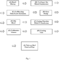
- Another aspect of the invention provides a method of producing a cross-linked polyolefin pipe comprising:
- the pipes of the invention may be used to convey fluids, for example drinking water or hot water. Accordingly, another aspect of the invention provides for the use of a pipe of the invention for the transport of water, e.g. in a water transport system.
- An embodiment provides the use of a pipe of the invention in a drinking water transport system.
- Another embodiment provides use of a pipe of the invention in a hot water transport system.
- Polymeric pipes of this invention may be used for variety of applications.
- One aspect of the present invention discloses the use of the pipes of the invention for water transport, for example for transport of hot and/or cold potable water, radiant floor heating, or waste water.
- the pipes of the present invention can be used in fire sprinklers, process pipes in industries such as the food industry, and for conveying fluids other than water such as gases and slurries, among other uses.
- These polymeric pipes include a base pipe with one or more layers disposed on the base pipe. Examples of various layers that may be disposed on a polymeric base pipe are included in US 2010/0084037 , entitled "Methods and Compositions for Coating Pipe".
- the polymeric pipe of the present invention can include base pipe with no layers disposed on the base pipe, i.e. the pipe will consist of a single (i.e. one) layer.
- Pipe standards and standard test procedures referenced in the present disclosure include the following:
- PEX tubing in North America must meet temperature and pressure ratings requirements of 160 psi at 73.4 °F (23 °C), 100 psi at 180 °F (82.2 °C), and 80 psi at 200 °F (93.3 °C). Minimum burst ratings are at 475 psi at 73.4 °F (5/8 inch and larger). Additional performance characteristics and requirements for PEX pipes and tubing are given in ASTM F867.
- Chlorine resistance is measured by ASTM F2023 and requires approximately 12-15 months of testing for completion.
- a qualitative measure of the level of stabilisation may be provided by the oxidative-induction time (OIT) test, as performed in accordance with ASTM D3895.
- OIT oxidative-induction time
- Specific additives are typically needed for any application where polymers are utilized to create consumer products.
- pipes for drinking water applications typically comprise stabilizers, anti-oxidants, crosslinking agents, processing additives, etc. as part of the final pipe composition, regardless of manufacturing method.
- These additives are typically necessary to provide pipes with desirable physical properties, e.g. pipes that satisfy ASTM F876 and / or EN ISO 15875 requirements.
- These chemical additives are, however, typically subject to leaching from the final chemical pipe. Leaching of chemicals into the pipe is, however, undesirable.
- NSF 61 relates to the hygiene requirement and concerns the need to minimize chemical leaching from the finished pipes.
- Drinking water pipes in North America must pass the NSF 61 test.
- the purpose of this test is to assure the customer that the quality of the water inside the pipe is not compromised by chemicals leaching into it.
- the water extracts are analyzed by a Gas Chromatograph equipped with a Mass Selective Detector (GC/MS). If deemed necessary other analytical techniques are also used. Twenty-four hours prior to collecting a sample for analysis some of the samples are heated at 82°C for 30 minutes. The heated extracts are then analyzed by GC/MS for semi-volatile compounds using EPA624 method. The rest of the samples are conditioned at room temperature and then analyzed by GC/MS for volatile compounds using EPA524 method.
- GC/MS Mass Selective Detector
- NSF 61 The allowance limits of NSF 61 were typically in the in the ppm range until recent years when the requirements have become more stringent, for example with the limits set in the ppb range for a number of compounds in current NSF standards.
- the degree of crosslinking can be quantified in accordance with the following citation from ASTM F876: "6.8. Degree of Crosslinking-When tested in accordance with 7.9, the degree of crosslinking for PEX tubing material shall be within the range from 65 to 89% inclusive. Depending on the process used, the following minimum percentages crosslinking values shall be achieved: 70% by peroxides (PEX-a), 65% by Azo compounds, 65% by electron beam (PEX-c), or 65% by silane compounds (PEX-b)". Ideally, pipes should have a high, i.e. at least 50% (preferably at least 65%), level of cross-linking according to the standard. However, in some applications a lower degree of cross-linking may be acceptable.
- the present invention is able to produce extruded pipes that consistently satisfy a defined target level of crosslinking (CCL) of, for example 73%, and importantly we have found that we are able to maintain it at that level at approximately 73 ⁇ 0.5% for a given formulation. In conventional prior art extrusion processes this variation is at least 3% and up to 5%, but can be many times higher.
- CCL crosslinking
- the present invention provides a process for producing pipes that may have a high CCL, i.e. a CCL of at least 65% (e.g. of at least 70%) in a consistent and homogeneous manner, to satisfy or exceed the ASTM F876 standard.
- Pipes of the invention may satisfy the NSF 61 standard for residuals.
- Pipes of the invention may have a high CCL and also satisfy the NSF 61 standard for residuals.
- alkyl C 1 -C 10 alkyl
- C x -C y alkyl (where x is at least 1 and less than 10, and y is a number greater than 10) as used herein include reference to a straight or branched chain alkyl moiety having, e.g. 1, 2, 3, 4, 5, 6, 7, 8, 9 or 10 carbon atoms.
- the term includes reference to, for example, methyl, ethyl, propyl (n-propyl or isopropyl), butyl (n-butyl, sec-butyl or tert-butyl), pentyl, hexyl and the like.
- alkyl may be a "C 1 -C 6 alkyl", i.e. an alkyl having 1, 2, 3, 4, 5 or 6 carbon atoms; or a "C 1 -C 4 alkyl", i.e. an alkyl having 1, 2, 3 or 4 carbon atoms.
- the term "lower alkyl” includes reference to alkyl groups having 1, 2, 3 or 4 carbon atoms.
- alkenyl C 2 -C 10 alkenyl
- C x -C y alkenyl (where x is at least 2 and less than 10, and y is a number greater than 10) as used herein include reference to a straight or branched chain alkyl moiety having, e.g. 2, 3, 4, 5, 6, 7, 8, 9 or 10 carbon atoms and having, in addition, at least one double bond, of either E or Z stereochemistry where applicable.
- alkenyl may be a "C 2 -C 6 alkenyl", i.e. an alkenyl having 2, 3, 4, 5 or 6 carbon atoms; or a "C 2 -C 4 alkenyl", i.e. an alkenyl having 2, 3 or 4 carbon atoms.
- the term "lower alkenyl” includes reference to alkenyl groups having 2, 3 or 4 carbon atoms.
- cycloalkyl as used herein includes reference to an alicyclic moiety having 3, 4, 5, 6, 7 or 8 carbon atoms in a single ring.
- the cycloalkyl may be functionalised with a group such as an epoxide to produce a cycloalkyl epoxide.
- a group of this type will comprise two fused rings.
- the cycloalkyl may be functionalised with a group such as an isocyanate to produce a cycloalkyl isocyanate.
- the group may be a bridged or polycyclic ring system, more than one of which may be functionalised with epoxide.
- a bridged or polycyclic ring system may comprise two rings, both of which are functionalised with epoxide.
- the term cycloalkyl includes reference to groups such as cyclopropyl, cyclobutyl, cyclopentyl, cyclohexyl, norbornyl, bicyclo[2.2.2]octyl and the like.
- alkoxy and C 1 -C 6 alkoxy as used herein include reference to -O-alkyl, wherein alkyl is straight or branched chain and comprises 1, 2, 3, 4, 5 or 6 carbon atoms. In one class of embodiments, alkoxy has 1, 2, 3 or 4 carbon atoms. This term includes reference to, for example, methoxy, ethoxy, propoxy, isopropoxy, butoxy, tert-butoxy, pentoxy, hexoxy and the like.
- lower alkoxy includes reference to alkoxy groups having 1, 2, 3 or 4 carbon atoms.
- halo or halogen as used herein includes reference to F, Cl, Br or I. In a particular class of embodiments, halogen is F or Cl, of which F is more common.
- the disclosure includes such a compound, moiety, process or product having that feature and also such a compound, moiety, process or product not having that feature.
- the disclosure comprises the unsubstituted moiety and the substituted moiety.
- CCL refers to the crosslink density, typically expressed as a percentage. Throughout the description and claims of this specification, the phrases “degree of crosslinking”, “level of crosslinking” and “crosslink density” or similar mean CCL.
- any reference to a specific component e.g. polyolefin structural polymer, photoinitiator, reactive extrusion species, co-agent, hindered amine light stabiliser, antioxidant, or any optional additive
- a specific component e.g. polyolefin structural polymer, photoinitiator, reactive extrusion species, co-agent, hindered amine light stabiliser, antioxidant, or any optional additive
- % by weight is a reference to the component as a % of its weight relative to the total weight of the layer of the pipe in which it is present.
- Polymeric pipes of the invention comprise a polyolefin structural polymer.
- the structural polymer may be polyethylene (PE), those of ordinary skill in the art understand that various other structural polymers may be used in place of polyethylene.
- the structural polymer may be a polyolefin such as PE (e.g., PE-raised temperature, or PE-RT), polypropylene (PP), polybutylenes (PB); any copolymers thereof; polyolefin copolymers such as poly(ethylene-co-maleic anhydride); among other polymers.
- the structual polymer may be polyethylene, polypropylene, polybutylene, and higher olefinic polymers; copolymers of ethylene, propylene, 1-butene, 2-butene, 1-pentene, 1-hexene, 1-heptene and 1-octene and isomers thereof with each other and with other unsaturated monomers. Block copolymers and polymer blends of polymerised monomers of any of the abovementioned polymers are also included.
- the polymeric pipe may have at least 85 % by weight polyolefin structural polymer, at least 90 % by weight polyolefin structural polymer, or at least 95 % by weight polyolefin structural polymer.
- Preferred polyolefin structural polymers for use in the present invention include polyethylene, polypropylene, and mixtures thereof.
- PE Polyethylene
- HDPE high density polyethylene
- MDPE medium density polyethylene
- UHMWPE ultra-high molecular weight polyethylene
- Examples of commercially available PE that may be used in pipes of the present invention include Basell Q 456, Basell Q 456B, Basell New Resin, Basell Q 471, (all three of which are available from Equistar Chemicals, LP Lyondell Basell Company, Clinton Iowa, United States) Borealis HE 1878, Borealis HE 1878 E, Borealis HE 2550 (all three of which are available from Borealis AG).
- the polymeric pipes of the invention may comprise cross-linked polyethylene (PEX) as the polyolefin structural polymer, in which case the pipe may be a PEX pipe.
- PEX polyethylene
- the structural polymer in such a pipe may comprise or consist of any of the varieties of polyethylene mentioned herein which has been crosslinked, preferably by the action of UV-radiation.
- the pipes of the invention may be pipes, for example PEX pipes, that meet temperature and pressure ratings requirements of 160 psi at 23 °C (73.4 °F), 100 psi at 82.2 °C (180 °F), and 80 psi at 93.3 °C (200 °F). Minimum burst ratings are at 475 psi at 23 °C (73.4 °F) (5/8 inch and larger). PEX pipes of the invention may also meet additional performance characteristics and requirements set out in the ASTM F 876 approved February 1, 2010, which is incorporated by reference in its entirety.
- Polymeric pipes may comprise a photoinitiator, for example one or more photoinitiators; e.g. at least 1, at least 2, at least 3, at least 4 or at least 5 photoinitiators as defined herein.
- the photoinitiator may be present in an amount of 0.02 to 3% by weight, for example 0.2 to 3% by weight, e.g. the photoinitiator may be present in an amount of 0.2 to 2.5% by weight or 0.2 to 2% by weight.
- the photoinitiator may be present in an amount of 0.3 to 1.5% by weight, 0.4 to 1.2% by weight, or 0.4 to 1% by weight; e.g. about 0.5 % by weight, about 0.75 % by weight or about 1% by weight.
- the photoinitiator has an important role in crosslinking the polyolefin structural polymer.
- the photoinitiator may be selected from the class of "Type II free radical Photoinitiators".
- Exemplary Type II photoinitiators include benzophenone and its derivatives, thioxanthone and its derivatives, anthraquinone and its derivatives, camphorquinone, benzyl, and dibenzosuberenone.
- Type II photoinitiators undergo a bimolecular reaction where the excited state of the photoinitiator normally interacts with a second molecule (co-initiator) to generate free radicals.
- the excited state can also abstract hydrogens from the surrounding polymer matrix, e.g., from a polyethylene polymer backbone, to induce and complete the necessary crosslinking, as being relevant in the present invention.
- the photoinitiator may be benzophenone or a benzophenone derivative.
- the photoinitiator may be selected from one or more of benzophenone, benzophenone substituted at the 4-position and benzophenone substituted at the 4 and 4'-position.
- the crosslinking process involves a radical mechanism to facilitate crosslinking. This process is illustrated below for the photoinitiator benzophenone and PE and comprises the steps of initiation, hydrogen abstraction and crosslinking.
- the photoinitiator is a benzophenone substituted at the 4-position or 4 and 4'-position of the following formula I :
- R 2 is selected from -H, -OH, -halo, -(C 1 - C 4 )alkyl, -(C 2 - C 4 )alkenyl, and formula II: R 2 may be selected from -H, -halo, -(C 1 - C 4 )alkyl and formula II. For example, R 2 may be -H or of formula II. For example, R 2 may be H.
- R 2 may be of formula II.
- R 3 is selected from -H, -halo, -OH, -(C 1 - C 4 )alkyl, -(C 2 - C 4 )alkenyl, -O(C 1 - C 4 )alkyl, and -O(C 2 - C 4 )alkenyl.
- R 3 may be selected from -H, -halo, and -OH.
- R 3 may be -H.
- R 3 may be -(C 1 - C 4 )alkyl.
- R 3 may be -O(C 1 - C4)alkyl.
- n 0, 1 or 2.
- m is 0 or 1.
- n 2, 3, 4, 5, 6.
- n is 3, 4 or 5.
- p is 2 - 10.
- p is 4, 5, 6, 7 or 8.
- q is 0, 1 or 2.
- q is 0 or 1.
- n and q may both be 1 and / or m and q may both be 0.
- n may be 3, 4 or 5 (e.g. 4) and p may be 3, 4, 5 or 6.
- Oligomeric / polymeric benzophenones are preferred, as these may result in less leaching of photoinitiator residues into fluid contained within the pipe.
- the photoinitiator may be a compound selected from benzophenone, 4-hydroxybenzophenone laurate, 4-hydroxybenzophenone stearate, 4-chloro-4'-hydroxybenzophenone laurate, 4-chloro-4'-hydroxybenzophenone stearate, 4, 4'-dimethylbenzophenone, 4, 4'-dimethoxybenzophenone, 4-chlorobenzophenone, 4-fluorobenzophenone, 4-fluoro-4'-hydroxybenzophenone, 4,4'-diallyloxybenzophenone, Omnipol BP, and Genopol BP.
- Omnipol BP is the compound:
- Genopol BP is the compound:
- the photoinitiator is Omnipol BP a satisfactory crosslinking value is obtained for the polyolefin polymer and we can meet the NSF 61 requirement for residuals, e.g. when used in a pipe of the invention comprising a scavenger.
- Polymeric pipes of the invention comprise a scavenger, for example one or more scavengers; e.g. at least 1, at least 2, at least 3, at least 4 or at least 5 scavengers ; wherein the scavenger is selected from (C 6 -C 30 alkyl)NCO, OCN(C 6 -C 30 alkyl)NCO, cycloalkyl isocyanate, multi-functional isocyanates, oligomeric isocyanates and polymeric isocyanate and/or cycloaliphatic epoxide and/or a cycloalkyloxetane, and/or nanoparticles, wherein the nanoparticles are defined as material having one dimension below 200 nm and are selected from nano-clays and aluminium oxide.
- a scavenger for example one or more scavengers; e.g. at least 1, at least 2, at least 3, at least 4 or at least 5 scavengers ; wherein the
- the scavenger (or total amount of scavengers) is present in an amount of 0.01 to 2% by weight.
- the scavenger may be present in an amount of 0.2 to 1% by weight, 0.3 to 0.7% by weight, e.g. about 0.5 % by weight.
- the scavenger is a reactive extrusion species
- the interaction is based on a reaction.
- the reactive extrusion species is an alkyl isocyanate
- the alkyl isocyanate is able to react with a hydroxyl group of a photoinitiator or a hydroxyl group residue of a photoinitiator to form a covalent linkage.
- an alkyl isocyanate would react with hydroxybenzophenone to form a urethane linkage between the alkyl group of the isocyanate and the benzophenone.
- the reactive extrusion species is an epoxide (e.g. a cycloalkyl epoxide)
- the epoxy moiety may react with an appropriate substituent of the photoinitiator (or residue of the photoinitiator) to form a covalent linkage.
- the alkyl or cycloaliphatic groups of the reactive extrusion species contribute to reduced leaching from the polymer matrix of the residues after reaction to form a covalent linkage.
- the alkyl or cycloaliphatic groups of the reactive extrusion species provide a portion of the compound that is compatible with a polyolefin structural polymer (e.g. a polyethylene). This compatibility provides a level of miscibility and homogeneity in the polymer blend that prevents the leaching of the reactive extrusion species and any bound residues out of the pipe.
- the reactive extrusion species may comprise (or be) an alkyl isocyanate, cycloalkyl isocyanate, an oligomeric isocyanate, and/or polymeric isocyanate.
- An alkyl isocyanate or cycloalkyl isocyanate may be a monofunctional or multi-functional isocyanate, e.g. may be a diisocyanate.
- the isocyanate may comprise an alkyl isocyanate, e.g. (C 6 - C 30 alkyl)NCO or e.g. OCN(C 6 - C 30 alkyl)NCO.
- the alkyl may be a straight chain or branched.
- the alkyl isocyanate may be a C12, C13, C13, C14, C15, C16, C17, C18, C19, C20, C21 or C22 alkylisocyanate, e.g. octadecylisocyanate.
- the isocyanate may comprise a cycloalkyl isocyanate, for example isophorone diisocyanate.
- the isocyanate may comprise a polymeric isocyanate, e.g. a polymeric isocyanate based on hexamethylene diisocyanate and/or isophorone diisocyanate. Mixtures of isocyanates may be used in the present invention.
- Exemplary isocyanates include octadecyl isocyanate, trans-cyclohexane diisocyanate (e.g. available from DuPont), Krasol NN32 (9% NCO, MDI based, available from Cray Valley, Exton, PA, USA); and Desmodur polyisocyanates available from Bayer Material Science (e.g. Desmodur W, BL 3175A, 4265 SN, DA-L, DN, HL BA, I, N 100, N 3200, N 3300A, N 3400, N 3600, XP 2617 and H).
- Desmodur polyisocyanates available from Bayer Material Science (e.g. Desmodur W, BL 3175A, 4265 SN, DA-L, DN, HL BA, I, N 100, N 3200, N 3300A, N 3400, N 3600, XP 2617 and H).
- isocyanates useful in the present invention are methylene diphenyl diisocyanate (MDI); Desmodur ® W (hydrogenated MDI); monomeric toluene diisocyanate (TDI) based derivatives such as Desmodur ® T65N, Desmodur ® T80, Desmodur ® T100; and L 67 MPA/X, L 67 BA (isocyanurate), L 1470 (isocyanurate), IL BA (isocyanurate), IL EA (isocyanurate), IL 1351 (isocyanurate), IL 1351 EA (isocyanurate), IL 1451 (isocyanurate), IL 1451 EA (isocyanurate), IL 1451 EA (isocyanurate), IL 1451 EA (isocyanurate), IL 1451 EA (isocyanurate), HL BA (isocyanurate), HL EA (isocyanurate); and prepolymers based on
- Examples of further isocyanates useful in the present invention are Rubinate M, Rubinate 5025, Rubinate 1245, Rubinate 1820, Rubinate 9016, Rubinate 9257, Rubinate 44, Rubinate 1680, Rubinate 9447, Rubinate 9480, Rubinate 9495, Rubinate 9009, Rubinate 9259, Rubinate 9041, Rubinate 9236, Rubinate 9040, Rubinate 9272, Rubinate 9511, Rubinate 9234, Rubinate 9271, Rubinate 1790, Rubinate 1670, Rubinate 1209, Rubinate 9465, Rubinate 1234; Suprasec 5025, Suprasec 9615, Suprasec 9582, Suprasec 9602, Suprasec 2004, Suprasec 9150, Suprasec 9561, Suprasec 9603, Suprasec 9608, Suprasec 9616, Suprasec 9611, Suprasec 9584, Suprasec 9610, Suprasec 2496, Suprasec 9600, Suprasec 9577, Suprasec 2029, Suprasec 7316,
- the reactive extrusion species may comprise (or be) an epoxide or another cyclic ether derivative (e.g. an oxetane); for example a cycloalkyl epoxide or a cycloalkyl ether derivative (e.g. a cycloalkyl oxetane).
- an epoxide or another cyclic ether derivative e.g. an oxetane
- a cycloalkyl epoxide or a cycloalkyl ether derivative e.g. a cycloalkyl oxetane
- cycloaliphatic epoxides useful as in the present invention are 3,4-epoxycyclohexylmethyl-3,4-epoxycyclohexane carboxylate, bis-(3,4-epoxycyclohexyl)adipate, methyl 3,4-epoxy-cyclobexane-carboxylate, ethyl 3,4-epoxycyclohexane-carboxylate, propyl 3,4-epoxycyclohexane-carboxylate,isopropyl 3,4-epoxycyclohexane-carboxylate, n-butyl-, s-butyl-, and t-butyl 3,4-epoxycydohexane-carboxylate; the various amyl and hexyl 3,4-epoxycyclohexane-carboxylates, methyl 3,4-epoxy-3-methyl-cyclohexane carboxylate, bis-
- the scavenger may comprise (or be) nanoparticles, for example inorganic nanoparticles.
- Nanoparticles are defined as materials having one dimension below 200 nm. Without being bound by any theory, it is believed that nanoparticles may act to adsorb residues of the photoinitiator or other polar components, thereby leading to reduced leaching of photoinitiator residues from the polymer matrix into any fluid (for example water) that is resident in the pipe.
- the improved results obtained using nanoparticles may be due in part to their extremely high aspect ratio compared to conventional fillers.
- Nanoparticles that are used as scavengers in the present invention are selected from nano-clays (e.g. intercalated and exfoiated (delaminated) clays (layered silicates)), aluminium oxide.
- nano-clays e.g. intercalated and exfoiated (delaminated) clays (layered silicates)
- aluminium oxide Preferably at least 50% of the nanoparticles are less than about 20 layers thick, the layers of the nanoparticles having a unit thickness of from about 0.7nm to 1.2nm.
- the nanoparticles may be layered silicates.
- Polymer-layered silicate composites can be divided into three general types; composites where the layered silicate acts as a normal filler, intercalated nanocomposites consisting of a regular insertion of the polymer material in between the silicate layers and exfoliated nanocomposites where 1 nm-thick layers are dispersed in the polymer material forming a monolithic structure on the microscale. All three types can be used in the pipes of the present invention.
- Layered silicates are believed to be especially beneficial in polymer compositions in accordance with the Invention due to their large surface area in comparison with some other nanoparticles.
- layered silicates includes natural clays and minerals, for example, montmorillonite and talc, and also synthesized layered silicates such as magadiite, mica, laponite, and fluorohectorite. These layered silicates may be subjected to various surface treatments with organic wetting or coating agents as appropriate to introduce pendant polar groups. Mixtures of different layered silicates, and mixtures of layered silicates with other nanoparticles, may also be used.
- suitable nanoparticles include montmorillonites, such as Cloisite 6A and Cloisite 15A (sodium montmorillonite modified with a quaternary ammonium salt) manufactured by Southern Clay Products. Further examples of suitable nanoparticles include aluminium oxide particles and/or a nanoclay such Nanomer 1.31 PS, surface modified nanoclay (Aldrich product No. 682632, available from Sigma-Aldrich, St-Loius, MO, USA on 01/04/2013).
- Polymeric pipes of the invention may comprise a co-agent, for example one or more co-agents; e.g. at least 1, at least 2, at least 3, at least 4 or at least 5 co-agents as defined herein.
- the selected co-agents (monomers and/or oligomers) used in the formulations in the present invention comprise at least one polymerizable double bond or reactive group.
- the co-agent provides additional crosslinks between the polyolefin chains of the polyolefin structural polymer.
- the co-agent thus acts to promote and enhance the efficiency of the crosslinking process, e.g. where the polyolefin structural polymer is polyethylene the co-agent enhances the crosslinking of the polyethylene chains to produce PEX.
- the co-agent (or total amount of co-agents) may be present in an amount of 0.02 to 10% by weight.
- the co-agent may be present in an amount of 0.1 to 5% by weight, 0.2 to 1% by weight, 0.3 to 0.7% by weight, e.g. about 0.5 % by weight.
- the co-agent may be selected from co-agents comprising reactive groups such as acrylates, allyl ethers, polybutadienes, vinyl ethers, and also unsaturated vegetable oils, such as soybean oil.
- the co-agent may be selected from acrylates, allyl ethers, polybutadienes and vinyl ethers.
- the co-agent may comprise a reactive carbon-carbon double bond.
- a reactive carbon-carbon double bond may be a carbon-carbon double bond that is a terminal carbon-carbon bond.
- a reactive carbon-carbon double bond may be a carbon-carbon double bond where one of the carbon atoms comprises two geminal hydrogen atoms.
- the co-agent may comprise multiple double bonds. We have discovered that this enhances the level of crosslinking.
- Preferred co-agents comply with NSF 61 requirements.
- Polymeric co-agents such as polybutadienes, or any polymer backbone containing unsaturated moieties may be used within the framework of the present invention, and will typically comply with NSF 61 requirements when used in pipes of the invention.
- acrylates can be used as co-agents, and include: 1,6-hexanediol diacrylate, 1,3-bytylene glycol diacrylate, diethylene glycol diacrylate, trimethylolpropane triacrylate, neopentyl glycol diacrylate, polyethylene glycol 200 diacrylate, tetraethylene glycol diacrylate, triethylene diacrylate, pentaerythritol tetraacrylate, tripropylene glycol diacrylate, ethoxylated bisphenol-A diacrylate, propylene glycol (mono) dimethacrylate, trimethylolpropane diacrylate, di-trimethylolpropane tetraacrylate, triacrylate of tris(hydroxyethyl) isocyanurate, dipentaerythritol hydroxypentaacrylate, pentaerythritol triacrylate, ethoxylated trimethylolpropane tri
- the co-agent may be an oligomer or a pre-polymer.
- the co-agent may be an oligomer or a pre-polymer having acrylate functionality, e.g. selected from polyurethane acrylates, epoxy acrylates, silicone acrylates, and polyester acrylates.
- Other exemplary co-agents include (meth)acrylated epoxies, (meth)acrylated polyesters, (meth)-acrylated silicones, (meth)acrylated urethanes/polyurethanes, (meth)acrylated polybutadiene, (meth)acrylated acrylic oligomers and polymers, and the like, and any combinations thereof.
- a preferred co-agent is an oligomer or pre-polymer that is a polyurethane acrylate, for example a Krasol NN prepolymer (available from Cray Valley, Inc., Exton, PA, USA).
- TMPTA trimethylolpropane triacrylate
- co-agents of use in the invention include the following:
- Poly BD 600E Hydroxy terminated and epoxidized polybutadiene having an average molecular weight of about 2,100 g/mol.
- Polybutadiene-Ricon wherein x and y are selected such that the average molecular weight is from about 1,000 to about 10,000 g/mol, preferably from about 2,000 to about 7,000 g/mol.
- Polybutadiene-Ricon 142 of average molecular weight 4,100 g/mol (CAS # 9003-17-2).
- Polybutadiene-Ricon 152 of average molecular weight 2,900 g/mol (CAS # 9003-17-2).
- Polybutadiene-Ricon 156 of average molecular weight 2,900 g/mol.
- Polybutadiene-Ricon 157 of average molecular weight 1,800 g/mol.
- TMPTA Trimethylolpropane triacrylate
- Poly(ethylene glycol) diacrylate (CAS #: 26570-48-9) where n is selected such that the average molecular weight is about 575 g/mol.
- Polybutadiene diacrylate (CAS #: 9003-17-2) of average molecular weight 2,200 g/mol.
- Krasol ® NN polyurethane prepolymer available from Cray Valley, Inc., Exton, PA, USA
- Krasol ® NN 32 9% NCO, MDI based, 56% vinyl content, viscosity of 12,000 Cps at 25 °C and/or Krasol ® NN 35.
- Polymeric pipes of the invention may comprise a hindered amine light stabilizer (HALS), for example one or more HALS; e.g. at least 1, at least 2, at least 3, at least 4 or at least 5 HALS as defined herein.
- HALS are compounds in which an amine group is sterically hindered by adjacent functional groups.
- the physical properties of structural polymers such as PE may tend to degrade over time when exposed to ultraviolet (UV) wavelengths of light.
- UV ultraviolet
- the total amount of HALS may be from 0.05 to 1% by weight, from 0.05 to 0.5 % by weight, from 0.07 to 0.3 % by weight, from 0.1 to 0.25 % by weight, or from 0.1 to 0.2 % by weight; or about 0.1 % by weight, or about 0.15 % by weight.
- WO 2010/138816 A1 discloses, at paragraph [0050] on pages 15 to 17, HALS that may be used in the pipes of the invention.
- the HALS may comprise a piperidine group.
- the HALS may be a compound of the following formula:
- Each R 7 and R 8 may be hydrogen or a C 1 -C 30 saturated or unsaturated aliphatic moiety.
- R 9 may be a C 2 -C 30 saturated or unsaturated straight, branched or cyclic aliphatic moiety such as a hydrocarbon (consisting only of carbon and hydrogen), an ester, an ether, or other suitable functional group.
- At least one of the R 7 groups at each of the 2 and 6 positions is a C 1 -C 30 saturated or unsaturated straight, branched or cyclic aliphatic moiety, while in other embodiments both of the R 7 groups at each of the 2 and 6 positions is a C 1 -C 30 saturated or unsaturated straight, branched or cyclic aliphatic moiety.
- one or both of the R 7 groups at the 2 and 6 positions in the piperidine ring are alkyl groups (e.g., a methyl or ethyl group), and R 8 is a hydrogen, methyl or ethyl group.
- R 9 may be a long chain (C 6 or greater, C 8 or greater, C12 or greater, or C 16 or greater) straight or branched aliphatic functional group, at least a portion of which is compatible with a nonpolar polyolefin structural polymer such as PE.
- R 9 may include an alicyclic structure such as a second piperidine ring. Where R 9 includes a piperidine ring, a portion of R 9 may act as a bridge between two piperidine rings. In some such embodiments, the bridge between the two piperidine rings may be a saturated aliphatic moiety or an unsaturated aliphatic moiety (e.g., it may contain a C-C double bond such as methylene).
- R 9 may also be included at other positions on the piperidine ring, for example at any one, any two, or at all three of, the 3, 4 and 5 positions on the piperidine ring.
- R 9 may be an ester of formula -R 10 C(O)OR 11 or -R 11 C(O)OR 10 .
- R 10 may be either the piperidine ring (where the ester moiety is attached directly to the piperidine ring) or an additional functional group (e.g., a C 1 -C 30 saturated or unsaturated aliphatic functional group) that functions as a bridging group between the ester moiety and the piperidine ring.
- R 11 may be a C 2 -C 30 saturated or unsaturated carbon-containing moiety, for example an aliphatic function group (e.g., a straight, branched or cyclic aliphatic group). R 11 together with the carbon atom of the ester moiety may form a C 2 -C 30 saturated or unsaturated ester.
- HALS of use in the present invention are the following:
- Cyasorb 3853 which may represented by formula which has a molecular weight of 379 g/mol.
- Chimassorb 944LD which may be represented by formula which has a molecular weight of 2000 to 3100 g/mol.
- Tinuvin 770 which may be represented by formula which has a molecular weight of 481 g/mol.
- Tinuvin 622 which may be represented by formula which has a molecular weight of 3100 to 4000 g/mol.
- the structure of the HALS of the invention contributes to reduced leaching from the polymer matrix.
- the relatively long chain fatty acid portions that do not act as bridging groups in the HALS Cyasorb 3853 provide a portion of the compound that is compatible with a polyolefin structural polymer (e.g. a polyethylene).
- This compatibility provides a level of miscibility and homogeneity in the polymer blend that both improves the burst strength of the finished pipe and prevents and / or reduces the leaching of the Cyasorb 3853 into any water that is resident within the pipe.
- Polymeric pipes of the invention may comprise an antioxidant, for example one or more phenolic antioxidants; e.g. at least 1, at least 2, at least 3, at least 4 or at least 5 antioxidants as defined herein.
- Antioxidants may be used to preserve the polymer blend during the production process, for example when the polymer blend is exposed to the elevated heat and pressure of the extrusion process. Specifically, the mechanical properties of some structural polymers, such as PE, will tend to deteriorate due to oxidative degradation when exposed to heat and pressure. For example, in some cases the deterioration will evidence as the formation of shorter chains, effectively decreasing the average molecular weight of the structural polymer and changing the characteristics of the structural polymer. Antioxidants act to prevent or limit such deterioration.
- Antioxidants may also facilitate the maintenance of pipe properties over time, especially when the pipe is exposed to chlorine or other oxidizing agents.
- a fluid e.g. potable water
- oxidizing agents such as chlorine
- Such oxidation may cause degradation in the properties of the structural polymer and the finished pipe.
- antioxidants tend to preserve the properties of the structural polymer in the presence of an oxidative environment.
- the total amount of antioxidant may be from 0.1 to 1 % by weight, from 0.25 to 0.75 % by weight, from 0.2 to 0.6 % by weight, from 0.38 to 0.57 % by weight, or about 0.5 wt%.
- Suitable antioxidants include phenolic antioxidants. Examples of such antioxidants are described in WO 2010/138816 A1 , which is incorporated by reference in its entirety. For example, WO 2010/138816 A1 discloses, at paragraph [0048] on pages 12 to 14, antioxidants that may be used in the pipes of the invention. Exemplary antioxidants that may be used in the polymeric pipes of the invention include:
- Certain pipes of the invention that comprise a hindered amine light stabilizer and / or an antioxidant may provide an oxidative resistance as measured under the OR test (described under the subheading "Assays" below) of greater than 50 years, greater than 75 years, greater than 100 years, greater than 150 years, or greater than 200 years. Certain AO/HALS combinations may also provide greater than 60 minutes, greater than 75 minutes, greater than 90 minutes, greater than 100 minutes, or greater than 125 minutes under the OIT test.
- Pipes of the invention may comprise further additives, for example the pipes may comprise processing aids, e.g. fluoropolymers.
- pipes of the present invention may comprise a fluoropolymer that is selected from 3M TM Dynamar TM polymer processing additives, e.g. 3M TM Dynamar TM Polymer Processing Additive FX 9613 (available from 3M Center, St. Paul, MN).
- the processing aid may be present at a level of from 0.01 to 1% by weight, for example 0.01 to 0.5% by weight; e.g. 0.02 to 0.4% by weight, 0.02 to 0.1% by weight.
- the material compositions for the pipes include combinations of at least one component selected from each of the following six classes of chemical compounds (and may include more than one component from one or more classes): polyolefin, most preferably polyethylene; photoinitiator(s); co-agent(s) (monomers and/or unsaturated oligomers and/or unsaturated polymers); anti-oxidant(s); and processing aids.
- polyolefin most preferably polyethylene
- photoinitiator(s) co-agent(s) (monomers and/or unsaturated oligomers and/or unsaturated polymers); anti-oxidant(s); and processing aids.
- the required components further include light stabilisers, such as hindered amine light stabilizer(s); and scavengers(s). All of these components may be as defined previously.
- Pipes may be manufactured in accordance with a method or process of the invention.
- the process of the present invention requires a co-rotating twin screw extruder to produce PEX pipes from an extrusion mixture, which comprises the polyolefin structural polmer, a photoinitiator in an amount of 0.02 to 3% by weight and a scavenger in an amount of 0.01 to 2% by weight; and a co-agent in an amount of 0.02 - 10% by weight, wherein the co-agent comprises at least one carbon-carbon double bond, and a phenolic antioxidant in an amount of 0.1 to 1% by weight; wherein the photoinitiator is a compound of formula I as defined above and wherein the scavenger is selected from (C 6 -C 30 alkyl)NCO, OCN(C 6 -C 30 alkyl)NCO, cycloalkyl isocyanate, multi functional isocyanates, oligomeric isocyanates and polymeric isocyanate and/or cycl
- the process requires the presence of at least one UV irradiator to achieve the crosslinking.
- the process may include a gear pump to ensure consistency of the extrudate.
- the process is based on photo-induced crosslinking (UV irradiation) which is very fast and has flexibility in material choice. However there is no premature crosslinking in the extruder.
- the apparatus of the invention is typically arrange "in line" as a single production line, for example to provide greater convenience. For the purposes of providing enhanced clarity in the schematic drawings, however, the apparatus has been split over Figure 2 and Figure 3 .
- the apparatus typically includes the following components:
- the process is based on the use of a photo-crosslinkable pipe formulation where a photoinitiator (PI) is added.
- PI photoinitiator
- the PI interacts with the UV irradiation to induce crosslinking of the pipe formulation to form crosslinked polyethylene, i.e., PEX.
- PEX crosslinked polyethylene
- the presence of the photoinitiator allows for the tubing to be crosslinked throughout the entire pipe wall.
- the pipes may be formulated according to the compositions and components described herein above. Pipes may also be formed using the formulations of the examples.
- the twin screws used in the extruder can in principle be constructed in two different ways, i.e., with a co-rotating or a counter-rotating design.
- the choice made in the case of the present invention is critical for a number of reasons. Ordinarily, it would be expected that a counter-rotating screw would be an efficient material pump relative to a single screw or a RAM extruder. This means it would be expected to increase the productivity i.e. line speed.
- a co-rotating extruder is actually an excellent tool for advanced material development and leads to consistent material as well as superior line speed.
- the co-rotating twin screws to be excellent material pumps for a material such as a thermoplastic polyolefin. Advantages of the arrangement used in this invention include excellent pipe homogeneity and efficient optimisation of pipe tolerances.
- the co-rotating twin screws are configured with a number of screw elements along the screw axis, which may be combined in a number of different configurations according to the nature of the input raw olefin and additives.
- the extruder body of typical co-rotating twin screws is constructed of barrels, which can be seen as separate reactors which also provide the flexibility to dedicate one or more specific barrels to perform in certain ways. For example, it is possible to performed direct injection of raw materials into specific zones of the process i.e. into specific barrels. It is also possible to control the conditions in each barrel independently.
- the two parallel co-rotating screws consist of a number of designed screw elements. They are arranged in a modular flexible design with typically 10 operative zones (barrels). Each barrel can have its own design and function (heating, cooling, etc.).
- the geometry of the screws is such that the channels are lengthwise open, i.e., there is opportunity for flow in axial direction; flow is possible both upstream and upstream.
- the screws are crosswise closed with conveying elements, i.e., multiple parallel paths along machine axis, i.e., no communication possible between channels. However, the screws can be made crosswise open with kneading elements, which gives opportunity for distributive mixing at expense of pressure generating capacity.
- the extruder can be designed to act as a true and efficient mixer.
- the co-rotating twin screws are drag flow pumps with forced displacement at intermesh.
- the heat introduced in the process of the invention is fundamentally controlled by shear rate, i.e., mechanical energy, optionally supplemented with heat added from external sources (barrel heating).
- Fibre, nanoparticles, and/or other fillers may be added directly to the extruder in controlled manner. Fibre for example, may be destroyed by a high shear counter-rotating screw if pre-mixed. For a co-rotating screw however, the fibre can be added late in the process at the end of the screw. This opens up the opportunity to produce composite pipes, as a homogeneous composite, in one single operation. Accordingly in the processes of the invention, Fibre, nanoparticles, and/or other fillers may be added near the end of the screw, thereby reducing the length of time that these components are exposed to shear forces compared to the other components.
- Liquids can be added in a controlled fashion, for example at the end of the extruder.
- a vacuum can be applied in a specific zone, which makes it possible to add components available as slurries or other liquids.
- the solvent can be removed prior to exit of the extrudate from the twin-screw extruder.
- Pigments, stabilizers, additional high performance polymers, etc. can also potentially be added sequentially in the extrusion process.
- the apparatus used in the methods of the invention is flexible in terms of the processing of different materials and dimensions of the produced pipes, for example because the screw design can easily be altered by re-designing individual screw elements, and/or by moving around existing screw elements.
- the method of the present invention may be performed with an extruder output of greater than 100 kg/h, e.g. greater than 150 kg/hr, greater than 200 kg/h, greater than 250 kg/hr or greater than 300 kg/h.
- a method of the invention may be performed at an extrusion rate of 100 to 500 kg / hr, 150 to 450 kg/hr, or 200 to 400 kg/hr.
- Pipe dimensions may be in the range 1 ⁇ 2" to 8" diameter, e.g. in the range 1 ⁇ 2" to 4" diameter.
- a 1 ⁇ 2" pipe may be extruded in the method of the present invention at a rate of about 140 kg/h and extrusion speed of about 30 m/min; while a 4" pipe may be extruded at a rate of about 2 m/min.
- the extrusion may be performed at a temperature of about 200 °C. It is therefore preferred that the additives used in the methods of the invention, e.g. photoinitiator(s); and/or co-agent(s); and/or anti-oxidant(s); and/or hindered amine light stabilizer(s); and/or scavengers(s); and/or and processing aids, are not subject to fuming at 200 °C.
- the additives used in the methods of the invention e.g. photoinitiator(s); and/or co-agent(s); and/or anti-oxidant(s); and/or hindered amine light stabilizer(s); and/or scavengers(s); and/or and processing aids, are not subject to fuming at 200 °C.
- the term UV curing is normally used when a combination of a photoinitiator and an appropriate monomer/oligomer UV lacquer formulation is exposed to ultraviolet radiation to form high performance thin coatings for various commercially established and well known applications.
- the methods of the invention may use highly efficient microwave powered UV lamps (for example microwave powered UV lamps provided by, e.g. Fusion UV Systems).
- the methods of the invention may use microwave powered UV lamps, e.g. highly efficient microwave powered UV lamps, to provide the UV radiation, which in combination with a photoinitiator and an optional co-agent facilitates crosslinking of for example polyethylene to form PEX pipes and tubing.
- Pipes of the invention can be assessed in relation to a number of parameters using standard tests that would be known to the person skilled in the art.
- a number of suitable assays are described below and other suitable assays have been described previously under the heading "Pipe Standards and Certifications".
- Parameters of interest include NSF 61 requirements for residues in drinking water conveyed by pipes and ASTM F2023 requirements for chlorine resistance.
- NSF 61 and ASTM F2023 are both incorporated herein by reference in their entirety.
- Stabiliser functionality testing is a measure of resistance to oxidative degradation and provides an indication of the long-term performance of pipes (e.g. PEX pipes), in relation to oxidative degradation, e.g. by chlorine in potable water.
- pipes e.g. PEX pipes
- OIT Oxidative Induction Time
- Oxidative Resistance (OR) test Another test that is performed on pipe samples to evaluate oxidative resistance is called the Oxidative Resistance (OR) test. This test is described in ASTM F 2023, which is incorporated herein by reference in its entirety. This test places chlorinated water in a pipe under a number of different combinations of elevated pressure and temperature until the pipe fails. The time until failure of the pipe at the different combinations of temperature and pressure is used to estimate the life of the pipe.
- ASTM F 876 Another test described in ASTM F 876 is the "Hoop Stress Stabilizer Test”. This test is used to demonstrate a pipe material's ability to withstand long term elevated temperature conditions and is described at point 7.10 of ASTM F 876. The method provides that the functionality of a stabilizer of a specific PEX compound shall be verified by hydrostatic testing of pipe made from compound. Test six pipe samples continuously for 3000h at a hoop stress of 0.70 MPa at 120 °C, or for 8000h at a hoop stress of 0.70 MPa at 110 °C. This test is used to demonstrate the specific compound's ability to withstand long temperature conditions set forth elsewhere in this standard.
- polyethyene pipes of the invention exceeded the standard and demonstrated effective stabilization for over 12500 hours.
- the tested pipes were made in accordance with the co-rotating twin screw method of the invention.
- the tested pipes comprised polyethylene as the structural polymer, 0.75 % by weight photoinitiator, 0.5% by weight phenolic antioxidant, 0.15 % by weight HALS and 1% by weight of a polybutadiene co-agent. This is better than the results obtained previously for other pipes made using prior art methods and different formulations.
- polyethylene pipes made using RAM extrusion demonstrated effective stabilisation for 3,000 to 3,500 hours or for over 5,000 hours.
- the improvement in this key performance parameter may be due to the improved homogeneity and distribution of the raw materials in the pipe wall.
- This effect is associated with the co-rotating twin screw extrusion method combined with photo-induced crosslinking to form a crosslinked polyolefin pipe. It is believed that this combination of features has a synergistic effect.
- Pipes of the invention when tested in accordance with an assay as set out in NSF 61, may have levels of residual that are less than or equal to the levels set out in Table 1.
- a pipe of the invention when tested in accordance with NSF 61 may have levels of benzene of less than or equal to 5 ppb, benzophenone of less than or equal to 30 ppb, benzhydrol of less than or equal to 50 ppb, p -hydroxybenzophenone of less than or equal to 10 ppb, p -hydroxybenzhydrol of less than or equal to 10 ppb, and p- formylbenzophenone of less than or equal to 10 ppb.
- a pipe of the invention when tested in accordance with NSF 61 may have levels of each of benzophenone, benzhydrol, p -hydroxybenzophenone, p -hydroxybenzhydrol and p -formylbenzophenone of less than or equal to 10 ppb; e.g. the level of each of these compounds may be less than 5 ppb.
- a pipe of the invention when tested in accordance with NSF 61 may have levels of each of benzophenone and p -hydroxybenzophenone of less than 8 ppb, e.g. less than 5 ppb.
- an NSF 61 analysis for a PEX pipe of the invention comprising octadecyl isocyanate scavenger revealed benzophenone at 5.5 ppb, benzhydrol at 1 ppb, p-hydroxybenzophenone at 6 ppm and, p -hydroxybenzhydrol at 2.5 ppb.
- Pipe homogeneity can be determined by analysis of tubing cross-sections by
- FTIR microscopy to determine the distribution of additives in the polymeric material across the wall of the pipe.
- the samples are prepared for analysis by cutting thin (approximately 25 ⁇ m thick) cross-sections of the polymeric pipe wall with a razor.
- the cross-sections are then transferred to a KBr salt plate for analysis with suitable FTIR microscope, for example a Nicolet iN10 FTIR microscope equipped with a mapping stage and integrated video camera for locating and specifying areas for analysis.
- An area map was defined for each sample to include both the inner and outer walls. Data is collected and processed to provide an area map that indicates the distribution of assayed additives in the pipe wall.
- This assay was performed on a PEX pipe made in accordance with the invention using a co-rotating twin screw extruder and a corresponding PEX pipe extruded by a single screw extruder.
- the results of the pipe homogeneity assay indicated that both the antioxidant Irganox 1076 and hindered amine light stabilizer Cyasorb 3853 were more homogeneously distributed in the PEX pipe of the invention.
- the degree of crosslinking may be measured in accordance with the testing protocol set out in ASTM F 876 at 7.9.
- a pipe of the invention may have a degree of crosslinking of about 65% to about 89%.
- the degree of crosslinking may be measured to be about 70% to about 80%, e.g. about 70% to about 75%.
- the degree of crosslinking may be about 73%, e.g. 73 ⁇ 1% or 73 ⁇ 0.5%.
- the components present in a polymeric pipe may be assessed by performing an assay that comprises taking a section of the pipe, extracting the section of the pipe with an organic solvent under controlled conditions and analysis the compounds extracted into the solvent using an analytical technique such as GC/MS.
- a suitable protocol for organic extraction is provided by the following method. 1 g of pipe sample is placed in 2 mL of xylene and allowed to condition at 70°C for 24 hours. After that, the remaining solid pipe sample is removed (for example by filtration) providing an extract comprising xylene and components extracted from the pipe sample. If a different amount of pipe sample is used, the amount of xylene may be varied in proportion to the amount of pipe sample.
- the extract may then be analysed by GC/MS to determine the components extracted from the pipe using standard methods.
- a suitable standard method of GC/MS analysis is set out in NSF International Standard / American National Standard for Drinking Water Additives 61-2011 (June 10, 2011) ("NSF 61") at B.7.4.2 "Gas chromatography/mass spectroscopy (GC/MS) analysis” and further specified under subheadings B.7.4.2.1 - B.7.4.2.4 on pages B14 to B16, the content of which is incorporated herein by reference.
- Table 2 lists the PE resins used in the examples and lists a number of properties of these resins, including density, melt flow, melting point and crystallinity.
- Table 3 indicates the molecular weight and molecular weight distribution of the PE resins. The molecular weight and molecular weight distributions were determined using gel permeation chromatography.
- CCL crosslinking
- Pipes have been manufactured on a co-rotating twin screw extruder in accordance with the methods of the invention for various pipes sizes. Exemplary line speeds and extruder outputs were as follows:
Claims (17)
- Tuyau polymère formé de :un polymère structurel polyoléfine ;un photoinitiateur en une quantité de 0,02 à 3 % en poids, etun capteur en une quantité de 0,01 à 2 % en poids ;dans lequel le photoinitiateur est un composé de formule I :
 R1 est choisi parmi -(CH2)m(C=O)[O(CH2)n]pO(C=O)(CH2)q-, -(C=O)(C5 à C24 alkyle), et -(C=O)(C5 à C24 alcényle) ;R2 est choisi parmi -H, -OH, -halo, -(C1 - C4) alkyle, -(C2 - C4) alcényle, et la formule II :
 R3 est choisi parmi -H, -halo, -OH, -(C1 - C4) alkyle, -(C2 - C4) alcényle, -O(C1 - C4) alkyle, et -O(C2 à C4) alcényle ;m vaut 0, 1 ou 2 ;n vaut 2, 3, 4, 5, 6 ;p vaut 2 à 10 ; ety vaut 0, 1 ou 2 ;dans lequel le capteur est choisi parmi (C6 - C30 alkyle)NCO, OCN(C6 - C30 alkyle)NCO, les isocyanates de cycloalkyle, les isocyanates multifonctionnels, les isocyanates oligomères et les isocyanates polymères, et/ou un époxyde cycloaliphatique, et/ou un cycloalkyloxétane , et/ou des nanoparticules, dans lequel les nanoparticules sont définies comme des matériaux ayant une dimension inférieure à 200 nm et sont choisis parmi les nano-argiles et l'oxyde d'aluminium.
 - Tuyau selon la revendication 1, dans lequel le capteur est une espèce d'extrusion réactive choisie parmi (C6 - C30 alkyle)NCO, OCN(C6 - C30 alkyle)NCO, l'isocyanate de cycloalkyle, l'isocyanate polymère et l'époxyde de cycloalkyle ; oudans lequel le capteur est ou comprend un ou plusieurs parmi (C6 - C30 alkyle)NCO, OCN(C6 - C30 alkyle)NCO, l'isocyanate de cycloalkyle, l'isocyanate polymère ; oudans lequel le capteur est CH3(CH2)16NCO ; oudans lequel le capteur est un isocyanate polymère, éventuellement un isocyanate polymère à base d'hexaméthylène diisocyanate et/ou d'isophorone diisocyanate ; oudans lequel le capteur est le 3,4-époxycyclohexylméthly-3,4-époxycyclohexanecarboxylate ; et/oudans lequel le capteur est présent à raison de 0,2 à 1 % en poids.
- Tuyau selon la revendication 1 ou 2, comprenant en outre :un co-agent en une quantité de 0,02 à 10 % en poids, dans lequel le co-agent comprend au moins une liaison double carbone-carbone réactive ; et/ouun antioxydant en une quantité de 0,1 à 1 % en poids.
- Tuyau selon l'une quelconque des revendications 1 à 3,dans lequel R2 est de formule II ou H ; et/oudans lequel R3 est H ; et/oudans lequel R1 est -(CH2)m(C=O)[O(CH2)n]pO(C=O)(CH2)q- ; éventuellement dans lequel m et q valent tous les deux 1 et/ou dans lequel n vaut 4 et p vaut 3 à 6; ou dans lequel R1 est - (C=O)(C5 - C24 alkyle) ; ou dans lequel le photoinitiateur est
 dans lequel r vaut entre 2 à 8, éventuellement dans lequel r est choisi de telle sorte que le photoinitiateur ait un poids moléculaire moyen d'environ 700 à environ 800 g/mol.
 - Tuyau selon l'une quelconque des revendications précédentes, dans lequel le photoinitiateur est en une quantité de 0,3 à 1,5 % en poids.
- Tuyau selon l'une quelconque des revendications précédentes, dans lequel le co-agent comprend au moins deux liaisons doubles réactives carbone-carbone ; et/oudans lequel le co-agent est choisi parmi ou comprend des acrylates, des polybutadiènes, des éthers allyliques, des éthers vinyliques et des huiles mono ou polyinsaturées ; et/oudans lequel le co-agent comprend un oligomère ou un prépolymère qui est un acrylate de polyuréthane ; oudans lequel le co-agent comprend un composé de formule suivante :
 où x et y sont choisis de telle sorte que le poids moléculaire moyen soit d'environ 1 000 à environ 10 000 g/mol, de préférence d'environ 2 000 à environ 7 000 g/mol ; oudans lequel le co-agent comprend au moins l'un parmi le triallylcyanurate ; le polybutadiène éventuellement choisi parmi le polybutadiène
 dans lequel n est choisi de telle sorte que le poids moléculaire moyen soit d'environ 2 000 à environ 10 000 g/mol, de préférence d'environ 4 000 à environ 7 000 g/mol, et il peut être de 3 000 ou 5 000 g/mol,le polybutadiène à terminaison hydroxy, le polybutadiène à terminaison hydroxy et époxyde, le diacrylate de polybutadiène ; ou le triacétate de triméthylolpropane ; ou dans lequel le co-agent comprend du triacétate de triméthylolpropane ; et/ou dans lequel le co-agent est en une quantité de 0,2 à 2 % en poids, éventuellement de 0,3 à 1,5 % en poids.
 - Tuyau selon l'une quelconque des revendications précédentes, comprenant en outre un stabilisateur de lumière à amine encombrée en une quantité de 0,05 à 1 % en poids ; éventuellement :dans lequel le stabilisateur de lumière à amine encombrée est choisi parmi :


 où R5 est un groupe alkyle enC2 - C24,
 qui a un poids moléculaire de 2000 à 3100 g/mol, ou
 qui a un poids moléculaire de 3100 à 4000 g/mol ; et/oudans lequel le stabilisateur de lumière à amine encombrée est en une quantité de 0,05 à 0,5 % ou de 0,1 à 0,3 % en poids.
 - Tuyau selon l'une quelconque des revendications précédentes, dans lequel l'antioxydant est un antioxydant phénolique ; éventuellement
dans lequel l'antioxydant comprend

- Tuyau selon l'une quelconque des revendications précédentes, dans lequel le polymère structurel polyoléfine est choisi parmi le polyéthylène, le polypropylène, le polybutylène, tout copolymère de ceux-ci ; et les copolymères polyoléfines tels que le poly(éthylène-co-anhydride maléique) ; oudans lequel le polymère structurel polyoléfine est choisi parmi le polyéthylène, le polypropylène et leurs mélanges ; oudans lequel le polymère structurel polyoléfine est choisi parmi le polyéthylène et le polypropylène ; oudans lequel le polymère structurel polyoléfine est ou comprend du polyéthylène haute densité (PEHD) avec un indice de fluidité à chaud (MFI) d'au moins 2 ou avec un indice de fluidité à chaud d'au moins 5.
- Tuyau selon l'une quelconque des revendications précédentes, dans lequel, lorsqu'il est testé conformément à la norme NSF 61, le niveau de résidus des composés suivants est au niveau spécifié :le benzène est inférieur ou égal à 5 ppb ;la benzophénone est inférieure ou égale à 30 ppb,le benzydrol est inférieur ou égal à 50 ppb,la p-hydroxybenzophénone est inférieure ou égale à 10 ppb,le p-hydroxybenzhydrol est inférieur ou égal à 10 ppb, etle p-formylbenzophénone est inférieur ou égal à 10 ppb ; et/oudans lequel le tuyau est un tuyau réticulé, éventuellement dans lequel le degré de réticulation est dans la plage d'environ 60 à environ 80 %, en outre éventuellement dans lequel le degré de réticulation est dans la plage d'environ 70 à environ 80 %, encore éventuellement dans lequel le degré de réticulation est dans la plage d'environ 70 % à environ 75 %.
- Tuyau selon l'une quelconque des revendications précédentes, dans lequel le tuyau est un tuyau en polyoléfine réticulée avec les caractéristiques d'un tuyau pouvant être obtenu par :extrusion d'un mélange comprenant le polymère structurel polyoléfine, le photoinitiateur et le capteur à partir d'une extrudeuse à double vis co-rotative pour former un tuyau extrudé ; etréticulation du polymère structurel en irradiant le tuyau extrudé par rayonnement UV.
- Tuyau selon l'une quelconque des revendications précédentes, dans lequel l'extrusion comprend le passage du mélange depuis l'extrudeuse à travers une pompe à engrenages puis une tête de filière.
- Procédé de production d'un tuyau en polyoléfine réticulée comprenant :l'extrusion d'un mélange à partir d'une extrudeuse à double vis co-rotative pour former un tuyau extrudé ; etla réticulation d'un polymère structurel polyoléfine en irradiant le tube extrudé par rayonnement UV,dans lequel le mélange d'extrusion comprend le polymère structurel polyoléfine, un photoinitiateur en une quantité de 0,02 à 3 % en poids et un capteur en une quantité de 0,01 à 2 % en poids ; et un co-agent en une quantité de 0,02 à 10 % en poids, dans lequel le co-agent comprend au moins une liaison double carbone-carbone réactive, et un antioxydant phénolique en une quantité de 0,1 à 1 % en poids ;dans lequel le photoinitiateur est un composé de formule I :
 R1 est choisi parmi -(CH2)m(C=O)[O(CH2)n]pO(C=O)(CH2)q-, -(C=O)(C5 - C24 alkyle), et -(C=O)(C5 - C24 alcényle) ;R2 est choisi parmi -H, -OH, -halo, -(C1 - C4) alkyle, -(C2 - C4) alcényle, et la formule II :
 R3 est choisi parmi -H, -halo, -OH, -(C1 - C4) alkyle, -(C2 - C4) alcényle, -O(C1 - C4) alkyle, et -O (C2 - C4) alcényle ;m vaut 0, 1 ou 2 ;n vaut 2, 3, 4, 5, 6 ;p vaut 2 à 10 ; etq vaut 0, 1 ou 2 ; etdans lequel le capteur est choisi parmi (C6 - C30 alkyle)NCO, OCN(C6 - C30 alkyle)NCO, les isocyanates de cycloalkyle, les isocyanates multifonctionnels, les isocyanates oligomères et les isocyanates polymères, et/ou un époxyde cycloaliphatique, et/ou des nanoparticules, dans lequel les nanoparticules sont définies comme des matériaux ayant une dimension inférieure à 200 nm et sont choisies parmi les nano-argiles et l'oxyde d'aluminium.
 - Procédé selon la revendication 13, dans lequel le polymère structurel polyoléfine est tel que défini dans la revendication 9 ; et/oudans lequel le capteur est une espèce d'extrusion réactive choisie parmi (C6 - C30 alkyle)NCO, OCN(C6 - C30 alkyle)NCO, l'isocyanate de cycloalkyle, l'isocyanate polymère et l'époxyde de cycloalkyle ; et/oudans lequel le capteur est présent à raison de 0,2 à 1 % en poids ; et/oudans lequel le photoinitiateur est tel que défini en outre dans la revendication 4 ou 5 ; et/oudans lequel le co-agent est tel que défini en outre dans la revendication 6 ; et/oudans lequel le mélange comprend en outre un stabilisateur à la lumière amine encombrée tel que défini dans la revendication 7 ; et/oudans lequel l'antioxydant est tel que défini en outre dans la revendication 8.
- Procédé selon la revendication 13 ou la revendication 14,dans lequel le tuyau en polyoléfine réticulée a un degré de réticulation dans la plage d'environ 60 à environ 90 %, éventuellement dans lequel le degré de réticulation est dans la plage d'environ 65 à environ 80 %, en outre éventuellement dans lequel le degré de réticulation est dans la plage d'environ 70 % à environ 80 %, encore éventuellement dans lequel le tuyau en polyoléfine réticulée a un degré de réticulation d'environ 70 à environ 75 % ; et/oudans lequel l'extrusion comprend le passage du mélange depuis l'extrudeuse à travers une pompe à engrenages puis une tête de filière ; et/oudans lequel, après irradiation, le tuyau en polyoléfine réticulée est étalonné par un dispositif d'étalonnage ; et/oudans lequel l'extrusion est réalisée à un débit d'extrudeuse supérieur à 100 kg/h, éventuellement supérieur à 200 kg/h.
- Procédé selon l'une quelconque des revendications 13 à 15, dans lequel le polymère structurel polyoléfine et au moins un composant sont injectés séparément dans l'extrudeuse,dans lequel l'au moins un composant est choisi parmi le photoinitiateur et, lorsqu'il est présent, le capteur et/ou le co-agent, et/ou l'antioxydant phénolique, et/ou le stabilisateur de lumière à amine encombrée ; etdans lequel le polymère structurel polyoléfine et l'au moins un composant sont mélangés par un élément de mélange de l'extrudeuse à double vis ; éventuellement :dans lequel l'au moins un composant comprend deux composants ou plus ; et/oudans lequel l'au moins un composant comprend soit le photoinitiateur soit le capteur ; ou le photoinitiateur, le co-agent et l'antioxydant phénolique ; et/oudans lequel l'au moins un composant comprend le photoinitiateur, le capteur, le co-agent, l'antioxydant phénolique et le stabilisateur de lumière à amine encombrée.
- Utilisation d'un tuyau polyoléfine selon l'une quelconque des revendications 1 à 12 pour le transport d'eau.
Priority Applications (1)
| Application Number | Priority Date | Filing Date | Title |
|---|---|---|---|
| PL14721288T PL2992044T3 (pl) | 2013-05-03 | 2014-04-23 | Rura poliolefinowa |
Applications Claiming Priority (2)
| Application Number | Priority Date | Filing Date | Title |
|---|---|---|---|
| US201361819038P | 2013-05-03 | 2013-05-03 | |
| PCT/EP2014/058218 WO2014177435A1 (fr) | 2013-05-03 | 2014-04-23 | Tuyau en polyoléfine |
Publications (2)
| Publication Number | Publication Date |
|---|---|
| EP2992044A1 EP2992044A1 (fr) | 2016-03-09 |
| EP2992044B1 true EP2992044B1 (fr) | 2022-01-12 |
Family
ID=54956172
Family Applications (1)
| Application Number | Title | Priority Date | Filing Date |
|---|---|---|---|
| EP14721288.0A Active EP2992044B1 (fr) | 2013-05-03 | 2014-04-23 | Tuyau en polyoléfine |
Country Status (11)
| Country | Link |
|---|---|
| US (2) | US9963573B2 (fr) |
| EP (1) | EP2992044B1 (fr) |
| JP (1) | JP6403230B2 (fr) |
| CN (1) | CN105209526B (fr) |
| CA (1) | CA2911329C (fr) |
| DK (1) | DK2992044T3 (fr) |
| ES (1) | ES2907046T3 (fr) |
| LT (1) | LT2992044T (fr) |
| PL (1) | PL2992044T3 (fr) |
| PT (1) | PT2992044T (fr) |
| WO (1) | WO2014177435A1 (fr) |
Families Citing this family (21)
| Publication number | Priority date | Publication date | Assignee | Title |
|---|---|---|---|---|
| CA2911329C (fr) | 2013-05-03 | 2021-05-18 | Uponor Innovation Ab | Tuyau en polyolefine |
| GB2525453A (en) * | 2014-04-23 | 2015-10-28 | Uponor Innovation Ab | Polyolefin pipe |
| GB201506876D0 (en) * | 2015-04-22 | 2015-06-03 | Uponor Innovation Ab | Polyolefin pipe |
| CN105482257B (zh) * | 2016-01-04 | 2019-03-08 | 武汉工程大学 | 一种自修复型高强度耐老化薄膜材料及其制备方法 |
| US11541581B2 (en) | 2016-09-02 | 2023-01-03 | Zurn Industries, Llc | Injection molded cold-expansion compression collar |
| US11543065B2 (en) | 2016-09-02 | 2023-01-03 | Zurn Industries, Llc | Extruded cold-expansion compression collar |
| US11054076B2 (en) | 2016-11-04 | 2021-07-06 | Zurn Industries, Llc | Reinforcing ring with sleeve |
| JP6863557B2 (ja) * | 2016-12-05 | 2021-04-21 | 出光興産株式会社 | 潤滑油組成物及びその製造方法 |
| DE202018107371U1 (de) * | 2018-12-21 | 2020-03-24 | Rehau Ag + Co | Formteil und vernetzbare Zusammensetzung zur Bildung des Formteils |
| CN109867864A (zh) * | 2018-12-27 | 2019-06-11 | 重庆普利特新材料有限公司 | 一种低密度高降噪聚丙烯纳米复合材料及其制备方法 |
| US11480271B2 (en) | 2019-03-26 | 2022-10-25 | Titeflex Corporation | Multilayer composite pipe and pipe assemblies including reflective insulation |
| US11466799B2 (en) | 2019-03-26 | 2022-10-11 | Titeflex Corporation | Multilayer composite pipe and pipe assemblies including reflective insulation |
| US11846370B2 (en) | 2019-03-26 | 2023-12-19 | Titeflex Corporation | Multilayer composite pipe and pipe assemblies including reflective insulation |
| US10995884B1 (en) | 2019-03-26 | 2021-05-04 | Titeflex Corporation | Multilayer composite pipe and pipe assemblies including reflective insulation |
| US11466798B2 (en) | 2019-03-26 | 2022-10-11 | Titeflex Corporation | Multilayer composite pipe and pipe assemblies including reflective insulation |
| CN113795368A (zh) * | 2019-05-02 | 2021-12-14 | Sabic环球技术有限责任公司 | 输送氯化水的管 |
| DE202019102584U1 (de) * | 2019-05-08 | 2020-08-11 | Rehau Ag + Co | Formteil und vernetzbare Zusammensetzung zur Bildung des Formteils |
| DE202019103147U1 (de) * | 2019-06-05 | 2020-09-08 | Rehau Ag + Co | Formteil und vernetzbare Zusammensetzung zur Bildung des Formteils |
| CA3226016A1 (fr) | 2021-07-08 | 2023-01-12 | Borealis Ag | Polyethylene destine a etre utilise dans la production de polyethylene reticule (per) |
| GB2607979B (en) * | 2021-11-30 | 2024-01-31 | Wavin Bv | Multi-layered pipe |
| CN115093633B (zh) * | 2022-06-08 | 2022-12-30 | 宝新高分子科技(广州)有限公司 | 一种陶瓷化防火阻燃电缆材料及其加工装置 |
Citations (3)
| Publication number | Priority date | Publication date | Assignee | Title |
|---|---|---|---|---|
| US20080045619A1 (en) * | 2006-08-02 | 2008-02-21 | Shawcor Ltd. | Photo-crosslinkable polyolefin compositions |
| WO2009072073A1 (fr) * | 2007-12-05 | 2009-06-11 | Uponor Innovation Ab | Tuyau en matière plastique fait de polyoléfine |
| US20100272937A1 (en) * | 2009-04-28 | 2010-10-28 | Sherman Jr Robert L | Polyethylene pipe resins |
Family Cites Families (36)
| Publication number | Priority date | Publication date | Assignee | Title |
|---|---|---|---|---|
| IN164745B (fr) | 1984-05-11 | 1989-05-20 | Stamicarbon | |
| JPH03180323A (ja) | 1989-12-08 | 1991-08-06 | Toyo Echo Kk | 熱収縮性蓋の製造方法 |
| JPH04185651A (ja) * | 1990-11-21 | 1992-07-02 | Fujikura Ltd | 架橋ポリオレフィン成形物の製法 |
| SE500503C2 (sv) * | 1990-12-07 | 1994-07-04 | Inst Polymerutveckling Ab | Förfarande och bestrålningsenhet för kontinuerlig tvärbindning av polyeten |
| JPH054235A (ja) * | 1991-06-25 | 1993-01-14 | Hitachi Cable Ltd | 樹脂成形体の製造方法 |
| FR2710344B1 (fr) | 1993-09-21 | 1995-11-17 | Inst Francais Du Petrole | Compositions de polyéthylènes réticulables, utilisées notamment pour la fabrication de tubes et de gaines flexibles. |
| DE4404041C1 (de) | 1994-02-09 | 1995-03-23 | Ruesch Willy Ag | Polymermaterial von medizinischen Instrumenten und Verfahren zur Herstellung des Polymermaterials |
| NL1008960C2 (nl) | 1998-04-22 | 1999-10-25 | Wavin Bv | Kunststofbuis met een uit meerdere lagen samengestelde wand. |
| AR023110A1 (es) | 1999-03-22 | 2002-09-04 | Loctite Corp | Articulos roscados con revestimiento deformable curado sobre los mismos |
| JP2001074182A (ja) | 1999-09-07 | 2001-03-23 | Toyo Tire & Rubber Co Ltd | 可とう伸縮継手の製造方法 |
| DE10058290A1 (de) | 2000-11-23 | 2002-05-29 | Basf Ag | Verfahren zur Stabilisierung von Polyolefinen |
| IL140541A0 (en) | 2000-12-25 | 2002-02-10 | Syfan Saad 99 Ltd | Improved process for the manufacture of thermoplastic shrink films |
| US6652943B2 (en) | 2001-06-04 | 2003-11-25 | Saint-Gobain Performance Plastics Corporation | Multilayer polymeric article with intercrosslinked polymer layers and method of making same |
| GB0125099D0 (en) * | 2001-10-18 | 2001-12-12 | Coates Brothers Plc | Multi-functional photoinitiators |
| GB2410308B (en) | 2004-01-20 | 2008-06-25 | Uponor Innovation Ab | Multilayer pipe |
| DE102004061983A1 (de) | 2004-12-23 | 2006-07-06 | Rehau Ag + Co. | Materialzusammensetzung zur Vernetzung |
| DE102004061987A1 (de) | 2004-12-23 | 2006-07-06 | Rehau Ag + Co. | UV-vernetzbare Materialzusammensetzung zur Herstellung von dampfsterilisierbaren mehrschichtigen Schläuchen |
| DE102004061986A1 (de) | 2004-12-23 | 2006-07-06 | Rehau Ag + Co. | Vernetzungsverfahren zur Herstellung von dampfsterilisierbaren mehrschichtigen Portschläuchen |
| DE102004061985A1 (de) | 2004-12-23 | 2006-07-06 | Rehau Ag + Co | TPV-Alternative |
| DE102004061982A1 (de) | 2004-12-23 | 2006-07-06 | Rehau Ag + Co. | Materialzusammensetzung zur UV-Vernetzung |
| DE102004061981A1 (de) | 2004-12-23 | 2006-07-06 | Rehau Ag + Co. | Materialzusammensetzung zur UV-Vernetzung |
| EP1731535A1 (fr) | 2005-06-07 | 2006-12-13 | Saudi Basic Industries Corporation Inc. | Procédé pour la polymérisation d'oléfines |
| US20070003720A1 (en) | 2005-06-22 | 2007-01-04 | Fina Technology, Inc. | Cocatalysts useful for preparing polyethylene pipe |
| DE102006017446A1 (de) | 2006-04-13 | 2007-10-18 | Rehau Ag + Co | Materialzusammensetzung für UV-vernetzbaren Portschlauch |
| DE102006017445A1 (de) | 2006-04-13 | 2007-10-18 | Rehau Ag + Co | Materialzusammensetzung für ein UV-vernetzbares Formteil |
| WO2008012325A2 (fr) | 2006-07-25 | 2008-01-31 | Coloplast A/S | Photo-durcissement de revêtements thermoplastiques |
| WO2008016518A2 (fr) | 2006-08-02 | 2008-02-07 | Exxonmobil Chemical Patents Inc. | Article en polymère à base de propylène |
| CN100546797C (zh) | 2006-09-06 | 2009-10-07 | 中国科学技术大学 | 紫外光交联聚烯烃绝缘电线电缆的生产方法及其紫外光辐照交联设备 |
| EP2126358A2 (fr) | 2007-03-07 | 2009-12-02 | Saint-Gobain Performance Plastics Corporation | Tubes multicouches |
| DE102007026751A1 (de) * | 2007-06-09 | 2008-12-11 | Inoex Gmbh | Verfahren zur Herstellung von peroxidvernetzten Polyethylen-Rohren in einer Extrusionslinie |
| WO2010040079A1 (fr) * | 2008-10-03 | 2010-04-08 | Uponor Innovation Ab | Procédés et compositions de revêtement de conduite |
| ES2607784T3 (es) | 2009-05-29 | 2017-04-04 | Uponor Innovation Ab | Métodos y composiciones para producir tubería que tiene resistencia oxidativa mejorada |
| BR112012008208A2 (pt) * | 2009-07-31 | 2016-03-08 | Coloplast As | método de preparação de elemento de dispositivo medico e dispositivo médico |
| DE102010046715A1 (de) | 2010-09-28 | 2012-03-29 | Rehau Ag + Co. | Verfahren zur Herstellung eines vernetzten Formteils und vernetztes Formteil, hergestellt nach dem Verfahren |
| CN103012939B (zh) * | 2012-09-29 | 2016-03-02 | 深圳市沃尔核材股份有限公司 | 一种紫外光交联热缩管材料及紫外光交联热缩管的生产方法 |
| CA2911329C (fr) | 2013-05-03 | 2021-05-18 | Uponor Innovation Ab | Tuyau en polyolefine |
-
2014
- 2014-04-23 CA CA2911329A patent/CA2911329C/fr active Active
- 2014-04-23 WO PCT/EP2014/058218 patent/WO2014177435A1/fr active Application Filing
- 2014-04-23 EP EP14721288.0A patent/EP2992044B1/fr active Active
- 2014-04-23 DK DK14721288.0T patent/DK2992044T3/da active
- 2014-04-23 JP JP2016511006A patent/JP6403230B2/ja active Active
- 2014-04-23 PL PL14721288T patent/PL2992044T3/pl unknown
- 2014-04-23 LT LTEPPCT/EP2014/058218T patent/LT2992044T/lt unknown
- 2014-04-23 CN CN201480024950.6A patent/CN105209526B/zh active Active
- 2014-04-23 ES ES14721288T patent/ES2907046T3/es active Active
- 2014-04-23 PT PT147212880T patent/PT2992044T/pt unknown
- 2014-04-23 US US14/787,865 patent/US9963573B2/en active Active
-
2018
- 2018-04-27 US US15/964,129 patent/US10392496B2/en active Active
Patent Citations (3)
| Publication number | Priority date | Publication date | Assignee | Title |
|---|---|---|---|---|
| US20080045619A1 (en) * | 2006-08-02 | 2008-02-21 | Shawcor Ltd. | Photo-crosslinkable polyolefin compositions |
| WO2009072073A1 (fr) * | 2007-12-05 | 2009-06-11 | Uponor Innovation Ab | Tuyau en matière plastique fait de polyoléfine |
| US20100272937A1 (en) * | 2009-04-28 | 2010-10-28 | Sherman Jr Robert L | Polyethylene pipe resins |
Non-Patent Citations (1)
| Title |
|---|
| KRUMM K: "ADVANCED EXTRUSION PROCESSES FOR POLYETHYLENES", PLASTICS, RUBBER AND COMPOSITES PROCESSING AND APPLICATIONS, ESSEX, GB, vol. 20, no. 4, 1 January 1993 (1993-01-01), pages 193 - 200, XP001041252 * |
Also Published As
| Publication number | Publication date |
|---|---|
| EP2992044A1 (fr) | 2016-03-09 |
| LT2992044T (lt) | 2022-03-25 |
| US20180258255A1 (en) | 2018-09-13 |
| DK2992044T3 (da) | 2022-04-04 |
| PT2992044T (pt) | 2022-02-22 |
| JP2016518498A (ja) | 2016-06-23 |
| CA2911329C (fr) | 2021-05-18 |
| US9963573B2 (en) | 2018-05-08 |
| WO2014177435A1 (fr) | 2014-11-06 |
| ES2907046T3 (es) | 2022-04-21 |
| CN105209526B (zh) | 2018-04-20 |
| US10392496B2 (en) | 2019-08-27 |
| CN105209526A (zh) | 2015-12-30 |
| US20160130420A1 (en) | 2016-05-12 |
| CA2911329A1 (fr) | 2014-11-06 |
| JP6403230B2 (ja) | 2018-10-10 |
| PL2992044T3 (pl) | 2022-05-02 |
Similar Documents
| Publication | Publication Date | Title |
|---|---|---|
| US10392496B2 (en) | Polyolefin pipe | |
| EP3134669B1 (fr) | Tuyau en polyoléfine | |
| EP2352785B1 (fr) | Procédés et compositions de revêtement de conduite | |
| EP3286260B1 (fr) | Tuyau en polyoléfine | |
| US7255134B2 (en) | Carbon black-containing crosslinked polyethylene pipe having resistance to chlorine and hypochlorous acid | |
| EP1654322A2 (fr) | Materiaux composites contenant des materiaux plastiques et du bois | |
| KR101583908B1 (ko) | 절연재 제조용 수지 조성물 및 절연재의 제조방법 | |
| US20060263603A1 (en) | Multilayer pellet and method for producing the same | |
| JP6604723B2 (ja) | 流体輸送配管 | |
| FR2710344A1 (fr) | Compositions de polyéthylènes réticulables, utilisées notamment pour la fabrication de tubes et de gaines flexibles. |
Legal Events
| Date | Code | Title | Description |
|---|---|---|---|
| PUAI | Public reference made under article 153(3) epc to a published international application that has entered the european phase |
Free format text: ORIGINAL CODE: 0009012 |
|
| 17P | Request for examination filed |
Effective date: 20151119 |
|
| AK | Designated contracting states |
Kind code of ref document: A1 Designated state(s): AL AT BE BG CH CY CZ DE DK EE ES FI FR GB GR HR HU IE IS IT LI LT LU LV MC MK MT NL NO PL PT RO RS SE SI SK SM TR |
|
| AX | Request for extension of the european patent |
Extension state: BA ME |
|
| DAX | Request for extension of the european patent (deleted) | ||
| STAA | Information on the status of an ep patent application or granted ep patent |
Free format text: STATUS: EXAMINATION IS IN PROGRESS |
|
| 17Q | First examination report despatched |
Effective date: 20171220 |
|
| RIC1 | Information provided on ipc code assigned before grant |
Ipc: F16L 9/12 20060101ALI20190730BHEP Ipc: B29C 35/10 20060101ALI20190730BHEP Ipc: C08K 5/132 20060101ALI20190730BHEP Ipc: C08J 3/28 20060101AFI20190730BHEP |
|
| GRAJ | Information related to disapproval of communication of intention to grant by the applicant or resumption of examination proceedings by the epo deleted |
Free format text: ORIGINAL CODE: EPIDOSDIGR1 |
|
| GRAP | Despatch of communication of intention to grant a patent |
Free format text: ORIGINAL CODE: EPIDOSNIGR1 |
|
| GRAP | Despatch of communication of intention to grant a patent |
Free format text: ORIGINAL CODE: EPIDOSNIGR1 |
|
| STAA | Information on the status of an ep patent application or granted ep patent |
Free format text: STATUS: GRANT OF PATENT IS INTENDED |
|
| INTG | Intention to grant announced |
Effective date: 20191111 |
|
| INTC | Intention to grant announced (deleted) | ||
| INTG | Intention to grant announced |
Effective date: 20191118 |
|
| GRAJ | Information related to disapproval of communication of intention to grant by the applicant or resumption of examination proceedings by the epo deleted |
Free format text: ORIGINAL CODE: EPIDOSDIGR1 |
|
| STAA | Information on the status of an ep patent application or granted ep patent |
Free format text: STATUS: EXAMINATION IS IN PROGRESS |
|
| INTC | Intention to grant announced (deleted) | ||
| GRAJ | Information related to disapproval of communication of intention to grant by the applicant or resumption of examination proceedings by the epo deleted |
Free format text: ORIGINAL CODE: EPIDOSDIGR1 |
|
| STAA | Information on the status of an ep patent application or granted ep patent |
Free format text: STATUS: GRANT OF PATENT IS INTENDED |
|
| GRAP | Despatch of communication of intention to grant a patent |
Free format text: ORIGINAL CODE: EPIDOSNIGR1 |
|
| GRAJ | Information related to disapproval of communication of intention to grant by the applicant or resumption of examination proceedings by the epo deleted |
Free format text: ORIGINAL CODE: EPIDOSDIGR1 |
|
| STAA | Information on the status of an ep patent application or granted ep patent |
Free format text: STATUS: EXAMINATION IS IN PROGRESS |
|
| INTG | Intention to grant announced |
Effective date: 20200911 |
|
| GRAP | Despatch of communication of intention to grant a patent |
Free format text: ORIGINAL CODE: EPIDOSNIGR1 |
|
| STAA | Information on the status of an ep patent application or granted ep patent |
Free format text: STATUS: GRANT OF PATENT IS INTENDED |
|
| INTC | Intention to grant announced (deleted) | ||
| INTG | Intention to grant announced |
Effective date: 20201012 |
|
| GRAJ | Information related to disapproval of communication of intention to grant by the applicant or resumption of examination proceedings by the epo deleted |
Free format text: ORIGINAL CODE: EPIDOSDIGR1 |
|
| STAA | Information on the status of an ep patent application or granted ep patent |
Free format text: STATUS: EXAMINATION IS IN PROGRESS |
|
| GRAP | Despatch of communication of intention to grant a patent |
Free format text: ORIGINAL CODE: EPIDOSNIGR1 |
|
| STAA | Information on the status of an ep patent application or granted ep patent |
Free format text: STATUS: GRANT OF PATENT IS INTENDED |
|
| INTC | Intention to grant announced (deleted) | ||
| INTG | Intention to grant announced |
Effective date: 20210310 |
|
| GRAJ | Information related to disapproval of communication of intention to grant by the applicant or resumption of examination proceedings by the epo deleted |
Free format text: ORIGINAL CODE: EPIDOSDIGR1 |
|
| STAA | Information on the status of an ep patent application or granted ep patent |
Free format text: STATUS: EXAMINATION IS IN PROGRESS |
|
| INTC | Intention to grant announced (deleted) | ||
| GRAP | Despatch of communication of intention to grant a patent |
Free format text: ORIGINAL CODE: EPIDOSNIGR1 |
|
| STAA | Information on the status of an ep patent application or granted ep patent |
Free format text: STATUS: GRANT OF PATENT IS INTENDED |
|
| INTG | Intention to grant announced |
Effective date: 20210804 |
|
| GRAS | Grant fee paid |
Free format text: ORIGINAL CODE: EPIDOSNIGR3 |
|
| GRAA | (expected) grant |
Free format text: ORIGINAL CODE: 0009210 |
|
| STAA | Information on the status of an ep patent application or granted ep patent |
Free format text: STATUS: THE PATENT HAS BEEN GRANTED |
|
| AK | Designated contracting states |
Kind code of ref document: B1 Designated state(s): AL AT BE BG CH CY CZ DE DK EE ES FI FR GB GR HR HU IE IS IT LI LT LU LV MC MK MT NL NO PL PT RO RS SE SI SK SM TR |
|
| REG | Reference to a national code |
Ref country code: GB Ref legal event code: FG4D |
|
| REG | Reference to a national code |
Ref country code: CH Ref legal event code: EP |
|
| REG | Reference to a national code |
Ref country code: DE Ref legal event code: R096 Ref document number: 602014082140 Country of ref document: DE |
|
| REG | Reference to a national code |
Ref country code: IE Ref legal event code: FG4D |
|
| REG | Reference to a national code |
Ref country code: AT Ref legal event code: REF Ref document number: 1462353 Country of ref document: AT Kind code of ref document: T Effective date: 20220215 |
|
| REG | Reference to a national code |
Ref country code: PT Ref legal event code: SC4A Ref document number: 2992044 Country of ref document: PT Date of ref document: 20220222 Kind code of ref document: T Free format text: AVAILABILITY OF NATIONAL TRANSLATION Effective date: 20220216 |
|
| REG | Reference to a national code |
Ref country code: NL Ref legal event code: FP |
|
| REG | Reference to a national code |
Ref country code: NO Ref legal event code: T2 Effective date: 20220112 |
|
| REG | Reference to a national code |
Ref country code: FI Ref legal event code: FGE |
|
| REG | Reference to a national code |
Ref country code: DK Ref legal event code: T3 Effective date: 20220328 |
|
| REG | Reference to a national code |
Ref country code: SE Ref legal event code: TRGR |
|
| REG | Reference to a national code |
Ref country code: ES Ref legal event code: FG2A Ref document number: 2907046 Country of ref document: ES Kind code of ref document: T3 Effective date: 20220421 |
|
| REG | Reference to a national code |
Ref country code: AT Ref legal event code: MK05 Ref document number: 1462353 Country of ref document: AT Kind code of ref document: T Effective date: 20220112 |
|
| PG25 | Lapsed in a contracting state [announced via postgrant information from national office to epo] |
Ref country code: RS Free format text: LAPSE BECAUSE OF FAILURE TO SUBMIT A TRANSLATION OF THE DESCRIPTION OR TO PAY THE FEE WITHIN THE PRESCRIBED TIME-LIMIT Effective date: 20220112 Ref country code: HR Free format text: LAPSE BECAUSE OF FAILURE TO SUBMIT A TRANSLATION OF THE DESCRIPTION OR TO PAY THE FEE WITHIN THE PRESCRIBED TIME-LIMIT Effective date: 20220112 Ref country code: BG Free format text: LAPSE BECAUSE OF FAILURE TO SUBMIT A TRANSLATION OF THE DESCRIPTION OR TO PAY THE FEE WITHIN THE PRESCRIBED TIME-LIMIT Effective date: 20220412 |
|
| PG25 | Lapsed in a contracting state [announced via postgrant information from national office to epo] |
Ref country code: LV Free format text: LAPSE BECAUSE OF FAILURE TO SUBMIT A TRANSLATION OF THE DESCRIPTION OR TO PAY THE FEE WITHIN THE PRESCRIBED TIME-LIMIT Effective date: 20220112 Ref country code: GR Free format text: LAPSE BECAUSE OF FAILURE TO SUBMIT A TRANSLATION OF THE DESCRIPTION OR TO PAY THE FEE WITHIN THE PRESCRIBED TIME-LIMIT Effective date: 20220413 Ref country code: AT Free format text: LAPSE BECAUSE OF FAILURE TO SUBMIT A TRANSLATION OF THE DESCRIPTION OR TO PAY THE FEE WITHIN THE PRESCRIBED TIME-LIMIT Effective date: 20220112 |
|
| PG25 | Lapsed in a contracting state [announced via postgrant information from national office to epo] |
Ref country code: IS Free format text: LAPSE BECAUSE OF FAILURE TO SUBMIT A TRANSLATION OF THE DESCRIPTION OR TO PAY THE FEE WITHIN THE PRESCRIBED TIME-LIMIT Effective date: 20220512 |
|
| REG | Reference to a national code |
Ref country code: DE Ref legal event code: R097 Ref document number: 602014082140 Country of ref document: DE |
|
| PG25 | Lapsed in a contracting state [announced via postgrant information from national office to epo] |
Ref country code: SM Free format text: LAPSE BECAUSE OF FAILURE TO SUBMIT A TRANSLATION OF THE DESCRIPTION OR TO PAY THE FEE WITHIN THE PRESCRIBED TIME-LIMIT Effective date: 20220112 Ref country code: SK Free format text: LAPSE BECAUSE OF FAILURE TO SUBMIT A TRANSLATION OF THE DESCRIPTION OR TO PAY THE FEE WITHIN THE PRESCRIBED TIME-LIMIT Effective date: 20220112 Ref country code: RO Free format text: LAPSE BECAUSE OF FAILURE TO SUBMIT A TRANSLATION OF THE DESCRIPTION OR TO PAY THE FEE WITHIN THE PRESCRIBED TIME-LIMIT Effective date: 20220112 Ref country code: EE Free format text: LAPSE BECAUSE OF FAILURE TO SUBMIT A TRANSLATION OF THE DESCRIPTION OR TO PAY THE FEE WITHIN THE PRESCRIBED TIME-LIMIT Effective date: 20220112 Ref country code: CZ Free format text: LAPSE BECAUSE OF FAILURE TO SUBMIT A TRANSLATION OF THE DESCRIPTION OR TO PAY THE FEE WITHIN THE PRESCRIBED TIME-LIMIT Effective date: 20220112 |
|
| PLBE | No opposition filed within time limit |
Free format text: ORIGINAL CODE: 0009261 |
|
| STAA | Information on the status of an ep patent application or granted ep patent |
Free format text: STATUS: NO OPPOSITION FILED WITHIN TIME LIMIT |
|
| PG25 | Lapsed in a contracting state [announced via postgrant information from national office to epo] |
Ref country code: AL Free format text: LAPSE BECAUSE OF FAILURE TO SUBMIT A TRANSLATION OF THE DESCRIPTION OR TO PAY THE FEE WITHIN THE PRESCRIBED TIME-LIMIT Effective date: 20220112 |
|
| 26N | No opposition filed |
Effective date: 20221013 |
|
| PG25 | Lapsed in a contracting state [announced via postgrant information from national office to epo] |
Ref country code: MC Free format text: LAPSE BECAUSE OF FAILURE TO SUBMIT A TRANSLATION OF THE DESCRIPTION OR TO PAY THE FEE WITHIN THE PRESCRIBED TIME-LIMIT Effective date: 20220112 Ref country code: LU Free format text: LAPSE BECAUSE OF NON-PAYMENT OF DUE FEES Effective date: 20220423 |
|
| PG25 | Lapsed in a contracting state [announced via postgrant information from national office to epo] |
Ref country code: SI Free format text: LAPSE BECAUSE OF FAILURE TO SUBMIT A TRANSLATION OF THE DESCRIPTION OR TO PAY THE FEE WITHIN THE PRESCRIBED TIME-LIMIT Effective date: 20220112 |
|
| PG25 | Lapsed in a contracting state [announced via postgrant information from national office to epo] |
Ref country code: IE Free format text: LAPSE BECAUSE OF NON-PAYMENT OF DUE FEES Effective date: 20220423 |
|
| PGFP | Annual fee paid to national office [announced via postgrant information from national office to epo] |
Ref country code: LT Payment date: 20230324 Year of fee payment: 10 |
|
| PGFP | Annual fee paid to national office [announced via postgrant information from national office to epo] |
Ref country code: NL Payment date: 20230419 Year of fee payment: 10 |
|
| P01 | Opt-out of the competence of the unified patent court (upc) registered |
Effective date: 20230602 |
|
| PGFP | Annual fee paid to national office [announced via postgrant information from national office to epo] |
Ref country code: PT Payment date: 20230413 Year of fee payment: 10 Ref country code: NO Payment date: 20230421 Year of fee payment: 10 Ref country code: IT Payment date: 20230420 Year of fee payment: 10 Ref country code: FR Payment date: 20230424 Year of fee payment: 10 Ref country code: ES Payment date: 20230627 Year of fee payment: 10 Ref country code: DK Payment date: 20230421 Year of fee payment: 10 Ref country code: DE Payment date: 20230420 Year of fee payment: 10 Ref country code: CH Payment date: 20230502 Year of fee payment: 10 |
|
| PGFP | Annual fee paid to national office [announced via postgrant information from national office to epo] |
Ref country code: SE Payment date: 20230420 Year of fee payment: 10 Ref country code: PL Payment date: 20230418 Year of fee payment: 10 Ref country code: FI Payment date: 20230419 Year of fee payment: 10 |
|
| PGFP | Annual fee paid to national office [announced via postgrant information from national office to epo] |
Ref country code: BE Payment date: 20230419 Year of fee payment: 10 |
|
| PGFP | Annual fee paid to national office [announced via postgrant information from national office to epo] |
Ref country code: GB Payment date: 20230419 Year of fee payment: 10 |
|
| PG25 | Lapsed in a contracting state [announced via postgrant information from national office to epo] |
Ref country code: HU Free format text: LAPSE BECAUSE OF FAILURE TO SUBMIT A TRANSLATION OF THE DESCRIPTION OR TO PAY THE FEE WITHIN THE PRESCRIBED TIME-LIMIT; INVALID AB INITIO Effective date: 20140423 |
|
| PGFP | Annual fee paid to national office [announced via postgrant information from national office to epo] |
Ref country code: LT Payment date: 20240327 Year of fee payment: 11 |