EP2991807B1 - Elektrowerkzeug mit hochsetzsteller - Google Patents
Elektrowerkzeug mit hochsetzsteller Download PDFInfo
- Publication number
- EP2991807B1 EP2991807B1 EP14720607.2A EP14720607A EP2991807B1 EP 2991807 B1 EP2991807 B1 EP 2991807B1 EP 14720607 A EP14720607 A EP 14720607A EP 2991807 B1 EP2991807 B1 EP 2991807B1
- Authority
- EP
- European Patent Office
- Prior art keywords
- output
- threshold
- bypass
- battery
- converter
- Prior art date
- Legal status (The legal status is an assumption and is not a legal conclusion. Google has not performed a legal analysis and makes no representation as to the accuracy of the status listed.)
- Active
Links
Images

Classifications
-
- H—ELECTRICITY
- H02—GENERATION; CONVERSION OR DISTRIBUTION OF ELECTRIC POWER
- H02J—CIRCUIT ARRANGEMENTS OR SYSTEMS FOR SUPPLYING OR DISTRIBUTING ELECTRIC POWER; SYSTEMS FOR STORING ELECTRIC ENERGY
- H02J7/00—Circuit arrangements for charging or depolarising batteries or for supplying loads from batteries
-
- B—PERFORMING OPERATIONS; TRANSPORTING
- B25—HAND TOOLS; PORTABLE POWER-DRIVEN TOOLS; MANIPULATORS
- B25F—COMBINATION OR MULTI-PURPOSE TOOLS NOT OTHERWISE PROVIDED FOR; DETAILS OR COMPONENTS OF PORTABLE POWER-DRIVEN TOOLS NOT PARTICULARLY RELATED TO THE OPERATIONS PERFORMED AND NOT OTHERWISE PROVIDED FOR
- B25F5/00—Details or components of portable power-driven tools not particularly related to the operations performed and not otherwise provided for
-
- H—ELECTRICITY
- H02—GENERATION; CONVERSION OR DISTRIBUTION OF ELECTRIC POWER
- H02M—APPARATUS FOR CONVERSION BETWEEN AC AND AC, BETWEEN AC AND DC, OR BETWEEN DC AND DC, AND FOR USE WITH MAINS OR SIMILAR POWER SUPPLY SYSTEMS; CONVERSION OF DC OR AC INPUT POWER INTO SURGE OUTPUT POWER; CONTROL OR REGULATION THEREOF
- H02M3/00—Conversion of dc power input into dc power output
- H02M3/02—Conversion of dc power input into dc power output without intermediate conversion into ac
- H02M3/04—Conversion of dc power input into dc power output without intermediate conversion into ac by static converters
- H02M3/06—Conversion of dc power input into dc power output without intermediate conversion into ac by static converters using resistors or capacitors, e.g. potential divider
- H02M3/07—Conversion of dc power input into dc power output without intermediate conversion into ac by static converters using resistors or capacitors, e.g. potential divider using capacitors charged and discharged alternately by semiconductor devices with control electrode, e.g. charge pumps
-
- H—ELECTRICITY
- H02—GENERATION; CONVERSION OR DISTRIBUTION OF ELECTRIC POWER
- H02J—CIRCUIT ARRANGEMENTS OR SYSTEMS FOR SUPPLYING OR DISTRIBUTING ELECTRIC POWER; SYSTEMS FOR STORING ELECTRIC ENERGY
- H02J2207/00—Indexing scheme relating to details of circuit arrangements for charging or depolarising batteries or for supplying loads from batteries
- H02J2207/20—Charging or discharging characterised by the power electronics converter
Definitions
- the present invention relates to a power tool as defined in the preamble of claim 1.
- the present invention also relates to a method for providing an electrical motor unit of a power tool with an output voltage U output , as defined in the preamble of claim 24.
- the present invention also relates to a computer program and to a computer program product.
- Power tools including an electrical motor unit are often provided with electrical power from a battery unit.
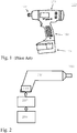
- Figure 1 schematically shows an example of such a power tool 100.
- the power tool 100 includes a body/housing 101 and a shaft/spindle 102.
- An electrical motor unit is used for driving the shaft 102.
- the electrical motor is driven by a battery unit 104.
- the battery unit 104 can be mounted at a handle 103 of the power tool, as shown in figure 1 , but can also be mounted on other parts of the power tool 100. However, the battery unit 104 can also be located separated from the power tool 100, and the electrical power can then be provided to the electrical motor unit by one or more cables that are connected between the external battery unit and the power tool 100.
- the power tool 100 further includes a number of parts not shown in figure 1 , as is understood by a skilled person.
- Power tools of today such as nut-runners, generally have problems relating to the size and weight of the power tool.
- There is generally a demand for reducing the size and/or the weight of the power tools since a small and lightweight power tool is very useful for the consumer, because it is easy to transport and also practical to use, since it is not too heavy to hold and handle.
- Power tools include a number of parts adding to the size and/or weight of the tool.
- One part having a big influence on the both the size and the weight of the tool is the battery unit.
- the performance of the power tool is today directly related to the power being supplied by the battery unit, and is thereby also directly related to the size and weight of the battery unit. For example, both the run-down speed and the torque provided by a nut-runner are directly related to a voltage level of the battery unit. Therefore an efficient and high performing nut-runner today has to be provided with a large and heavy battery pack.
- the set of battery units that can be used in the power tool must still be carried along with the power tool by a user to achieve adaptability of performance and size of the tool. Also, all battery units have to be charged for the user to be able to adapt the battery supply during work with the tool, which makes this solution not very practical. Also, battery units and/or batteries having different powers and/or voltages are today often provided with different connection interfaces. Thus, a first battery having a first voltage/power may be directly connectable to the power tool while a second battery having a second voltage/power is often not directly connectable to the power tool. It might therefore be difficult to efficiently interchange the batteries, at least without the use of one or more battery adapters.
- the present invention aims to provide a more compact and lightweight power tool than the power tools known in the background art.
- the object is also achieved by the above mentioned method for providing an electrical motor unit of a power tool with an output voltage U output , according to the characterizing portion of claim 25.
- the power tool and method according to the present invention are characterized in that an output voltage U output that is provided to an electrical motor unit in the tool may be switched between a battery voltage U battery and a higher step-up voltage U step-up .
- This switchable output voltage U output is according to the claimed invention achieved by a step-up converter, a bypass circuit, and at least one control unit controlling the step-up converter and the bypass circuit.
- the step-up converter is connectable between a battery unit and the electrical motor unit and is arranged for converting, when enabled, a battery voltage U battery being provided to the step-up converter by the battery unit to a higher step-up voltage U step-up ; U step-up > U battery .
- This step-up voltage U step-up is then provided to the electrical motor unit as an output voltage U output ;
- U output U step-up ⁇
- At least one control unit is arranged for controlling the step-up converter and the bypass circuit in order to switch the output voltage U output between the battery voltage U battery and the step-up voltage U step-up .
- This controlled switching can be achieved by generating a bypass enabling/disabling signal S bypass_on/off and a step-up enabling/disabling signal S step-lip_on/off , and by proving these enabling/disabling signals to the bypass circuit and the step-up converter, respectively.
- the power tool according to the present invention can utilize enabling/disabling of the bypass circuit and the step-up converter, respectively, to alter the output voltage U output that is provided to the motor unit such that a temporally increased rotational speed of the electrical motor unit is achieved.
- productivity of the power tool is increased.
- a smaller and lighter battery unit, and thereby a more compact and less heavy power tool, as compared to prior art power tools, can be provided by the present invention.
- a compact and lightweight power tool is easily handled and therefore the usage of the power tool is improved by the present invention.
- the power tool can be particularly adapted to perform certain activations of the tool, such as tightening and/or loosening of nuts, during which the speed and/or torque should change during the activation to achieve optimal performance.
- the step-up converter can be enabled and the bypass circuit can be disabled during a first phase of the tool activation.
- the bypass circuit can be enabled and the step-up converter can be disabled.
- a high rotational speed and low torque is provided by the power tool during the first phase, followed by a lower rotational speed and higher torque during the second phase. This gives an optimal performance for e.g.
- this optimal performance is achievable with a compact and lightweight power tool.
- the first phase can instead provide a high torque T and low rotational speed
- the second phase can provide a high rotational speed and a low torque.
- This is achieved by enabling the bypass circuit and disabling the step-up converter during the first phase of the activation, followed by enabling the step-up converter and disabling the bypass circuit during the second phase.
- This gives an optimal performance to e.g. a compact and lightweight nut-runner when loosening a nut, where much rotational force is needed during the first phase, and much less rotational force is needed during the second phase.
- the power tool includes a step-up converter, a bypass circuit, and at least one control unit as will be explained in detail below.
- Figure 2 schematically shows such a power tool 200.
- the step-up converter, the bypass circuit, and the one or more control units are illustrated as a step-up/bypass module 202 being connectable between a battery unit 204 and an electrical motor unit 203 located within the body 201 of the tool 200.
- the step-up module 202 i.e. the step-up converter, the bypass circuit, and the one or more control units, is arranged integrated within the body 201 of the power tool 200, and is connected to the electrical motor unit 203 and to the battery unit 203.
- the step-up/bypass module 202 is integrated with the battery unit 204.
- the integrated battery and step-up/bypass module 202, 204 is connectable to the motor unit 203 of the tool 200.
- the step-up/bypass module 202 is arranged separately, i.e. as a separate unit, between the battery unit 204 and the motor unit 203.
- the separately arranged step-up/bypass module 202 is here thus connectable to both the battery unit 204 and to the motor unit 203.
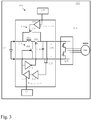
- FIG. 3 schematically shows a power tool 300 according to the present invention.
- the power tool 300 is schematically illustrated as including the battery unit 304 and the step-up/bypass module 302.
- the battery unit 304 and/or the step-up/bypass unit 302 and/or the one or more control units 331, 332 can also be arranged separately from the power tool 300, i.e. external from the body of the power tool.
- the power tool 300 includes an electrical motor unit 303, which is connectable to the battery unit 304 via the step-up/bypass module 302.
- an inverter 305 is included in the electrical motor unit 303.
- the inverter 305 may be omitted in the power tool 300 depending on the construction of the electrical motor unit 303 and/or of the step-up/bypass module 302, the inverter 305 may be omitted in the power tool 300.
- the step-up/bypass module 302 includes a step-up converter 310 and a bypass circuit 320.
- the step-up converter 310 is connectable between the battery unit 304 and the electrical motor unit 303.
- the step-up converter 310 can be enabled and disabled, and is arranged for converting, when enabled, a battery voltage U battery being provided to the step-up converter 310 by the battery unit 304.
- the step-up converter 310 thereby converts the battery voltage U battery to a higher step-up voltage U step-up ; U step-up > U battery .
- the electrical motor unit 303 is provided with the higher step-up voltage U step-up when the step-up converter 310 is enabled.
- the bypass circuit 320 is arranged in parallel with the step-up converter 310, and is thus also connectable between the battery unit 304 and the electrical motor unit 303.
- the bypass circuit 320 When the bypass circuit 320 is enabled, the battery unit 304 is connected to the electrical motor unit 303 through the bypass circuit 320.
- the power tool can also be equipped with a brake chopper arranged for protecting the battery unit 304 by preventing the output voltage U output on the output DC bus 325 to reach too high levels when the electrical motor unit 325 is braked/decelerated.
- a brake chopper arranged for protecting the battery unit 304 by preventing the output voltage U output on the output DC bus 325 to reach too high levels when the electrical motor unit 325 is braked/decelerated.
- energy is created by the electrical motor unit 303 when a user lets go of the tool trigger, whereby the rotational speed of the power tool is reduced, especially if the higher step-up voltage U step-up has been provided to the electrical motor unit before braking the electrical motor unit is initiated.
- the brake chopper can be arranged at the output DC bus 325, between the step-up/bypass module 302 and the electrical motor unit 303.
- the brake chopper can be implemented as a resistance coupled in series with a switch, such as a MOSFET (Metal Oxide Semiconductor Field Effect Transistor), over the output DC bus 325, and with a diode coupled in parallel with the resistance.
- a switch such as a MOSFET (Metal Oxide Semiconductor Field Effect Transistor)
- MOSFET Metal Oxide Semiconductor Field Effect Transistor
- the power tool 300 further includes at least one control unit 331, 332.
- the at least one control unit 331, 332 is arranged for controlling the step-up converter 310 and the bypass circuit 320 by enabling/disabling the step-up converter 310 and the bypass circuit 320.
- the output voltage U output on the output DC bus 325 may hereby be switched between the battery voltage U battery and the step-up voltage U step-up .
- the output voltage U output on the output DC bus 325 can be toggled between the lower battery voltage U battery and the higher step-up voltage U step-up ;
- the power tool 300 according to the present invention can thus temporally increase the rotational speed of the electrical motor unit 303 by providing the temporally increased step-up voltage U step-up to the electrical motor unit 303.
- the productivity of the power tool 300 is increased.
- a smaller and lighter battery unit 304, and thereby a more compact and less heavy power tool 300 is provided by the present invention.
- a compact and lightweight power tool 300 is easily handled, and therefore easier more attractive usage of the power tool 300 is facilitated by the invention.
- the step-up and bypass module 302 can be made compact and lightweight according to the solution of the present invention. This is due to the use of the bypass circuit 320 according to the invention.
- the bypass circuit 320 When the motor 303 provides a high effect during heavy load, the bypass circuit 320 is enabled and the step-up converter 310 is disabled, whereby the battery unit 304 is directly coupled to the motor unit 303, possibly including an inverter 305.
- the components of the step-up converter 310 only have to be able to cope with a limited power, since the step-up converter 310 is bypassed when a maximum power is provided from the battery unit 304 to the motor unit 303.
- the step-up and bypass module 302 can be designed to be compact and lightweight, which also reduces the total size and weight of the power tool 300.
- the step-up converter 310 is a synchronous step-up converter, which is arranged for creating the higher step-up voltage U step-up , said step-up converter including at least one step-up transistor 311, at least one inductor 313, and at least one step-up switch 312.
- the at least one step-up transistor 311 and/or the at least one step-up switch 312 can typically be switched at a relatively high frequency, e.g. at a frequency in the kilohertz (kHz) range.
- the inductor 313 is coupled in series with the battery unit 304 and the step-up switch 312.
- the step-up transistor 311 is coupled in parallel with the battery unit 304 and in parallel with an output capacitor 314 that is coupled over the output DC bus 325.
- the step-up converter can further include a step-up control circuitry being arranged for controlling the at least one step-up transistor 311 and/or the at least one step-up switch 312, where the step-up switch 312 can be used for connecting the step-up converter 310 to the output DC bus 325, i.e. to the electrical motor unit 303, when enabled.
- the step-up control circuitry includes a voltage regulation circuitry 316 and a PWM (Pulse Width Modulation) circuit 317.
- the voltage regulation circuitry 316 which can be implemented as an amplifier, is arranged for controlling the level of the higher step-up voltage U step-up towards its target voltage U target by controlling the PWM circuit 317.
- the voltage regulation circuitry 316 has the output DC bus 325 as an input 315.
- the PWM circuit 317 also includes an overload limiting function, which limits/reduces the step-up voltage U step-up if the step-up converter 310 is overloaded.
- the PWM circuit 317 also has an input receiving a control signal S step-up_on/off being provided from a control unit 332 as an input signal.
- the function of the at least one step-up transistor 311 and the at least one step-up switch 312 is thus controlled by the step-up control circuitry, and in particular by the PWM circuit 317.
- the control signal that is used for controlling the step-up transistor 311 is provided directly by the PWM circuit 317.
- the control signal that is used for controlling the step-up switch 312 is an amplified and inverted version of the control signal provided by the PWM circuit 317, where the amplification and inversion are performed by the amplifier/inverter 318.
- the bypass circuit 320 includes a bypass switch 321, which is controllable by a control unit 331 providing a bypass control signal S bypass_on/off .
- the bypass switch 321 is switched at a very low frequency, e.g. twice per activation of the tool, as will be described more in detail below.
- An amplifier 322 can be used for amplifying the bypass control signal S bypass_on/off from the control unit 331 before providing the amplified control signal to the bypass switch 321.
- control units 331, 332 providing the control signals S bypass_on/off and S step-up_on/off are illustrated as two separate control units. However, as is clear for a skilled person, both of these control signals S bypass_on/off and S step-up_on/off can also be provided by a single control unit, essentially including the above and/or below described functions of both of these control units 331, 332.
- one or more of the at least one step-up switch 311, the step-up switch 312, and the at least one bypass switch 321 are implemented as an N-channel MOSFET (Metal Oxide Semiconductor Field Effect Transistor), an P-channel MOSFET (Metal Oxide Semiconductor Field Effect Transistor), or another suitable controllable switching device.
- MOSFET Metal Oxide Semiconductor Field Effect Transistor
- P-channel MOSFET Metal Oxide Semiconductor Field Effect Transistor
- At least one of the step-up switch 312 and the at least one bypass switch 321 are implemented as power diodes, which are especially suitable for lower power applications.
- the step-up converter 310 is a multi-phase converter that is adapted to convert the battery voltage U battery to a higher step-up voltage U step-up .
- the multi-phase converter can be a boost type converter, being controllable by the control signal S step-up_on/off .
- the step-up converter 310 is implemented as including two step-up transistor circuits that is operated in mutually opposite phases.
- a smooth output step-up voltage U step-up can be provided by the step-up converter 310, since a voltage/current ripple on the output DC bus 325 can be reduced by the opposite phase coupled transistor configuration.
- the battery unit 304 includes at least one super capacitor.
- Super capacitors have a very high capacitance value per unit volume and a very high energy density.
- the super capacitors can thus be utilized as a reliable energy source, as an alternative to a conventional battery.
- the super capacitors are also very lightweight, much lighter than a corresponding conventional battery energy source.
- One problem with super capacitors is that they lose their power after a while. However, it is possible to very quickly recharge them again.
- the output voltage of the super capacitor can be boosted when needed, e.g. when the super capacitor has lost some of its power.
- the power tool according to the invention e.g.
- a super capacitor in the battery unit can be used in an assembly line, where the tool could be used for sequential relatively short time periods and could be recharged between these short time periods.
- the tool could be used for sequential relatively short time periods and could be recharged between these short time periods.
- the at least one control unit 331, 332 is, according to the invention, arranged for providing the bypass circuit 320 with a bypass enabling/disabling signal S bypass_on/off .
- the bypass circuit 320 is arranged for enabling/disabling the bypass, i.e. for connecting/disconnecting the battery unit 304 to the electrical motor unit 303 based on the bypass enabling/disabling signal S bypass_on/off .
- the at least one control unit 331, 332 is arranged for providing the step-up converter 310 with a step-up enabling/disabling signal S step-up_on/off .
- the step-up converter 310 is arranged for enabling/disabling the voltage conversion of the step-up converter 310 based on that step-up enabling/disabling signal S step-up_on/off .
- the bypass enabling/disabling signal S bypass_on/off and the step-up enabling/disabling signal S step-up_on/off are complementary signals.
- the bypass enabling/disabling signal S bypass_on/off and the step-up enabling/disabling signal S step-up_on/off have inverse values.
- the bypass enabling/disabling signal S bypass_on/off is an inverse/negated version of the step-up enabling/disabling signal S step-up_on/off .
- the at least one control unit 331,332 can preferably be utilized for toggling the output DC bus 325 between the battery voltage U battery and the higher step-up voltage U step-up , thereby providing a power tool 300 having the above mentioned advantages of the present invention.
- a compact and lightweight power tool having high productivity is thus provided by the invention.
- the voltage on the output DC bus 325 can be switched between the battery voltage U battery and the higher step-up voltage U step-up based on an step-up enabling/disabling signal S step-up_on/off that is provided to the PWM circuit 317 by the at least one control unit 331, 332 and/or based on a bypass enabling/disabling signal S bypass_on/off that is provided to the bypass switch 321 by the at least one control unit 331, 332.
- step-up enabling/disabling signals S step-up_on/off and the bypass enabling/disabling signals S bypass_on/off are thus created in the at least one control unit 331, 332.
- the form of these step-up enabling/disabling signals S step-up_on/off and bypass enabling/disabling signals S bypass_on/off can be determined by the at least one control unit based on a number of different parameters, either based on single parameter values taken alone, or on two or more parameters in combination.
- the at least one control unit is arranged to base the step-up S step-up_on/off and/or bypass S bypass_on/off enabling/disabling signals on a relation between the output voltage U output on the output DC bus 325 and a voltage threshold U threshold .
- a step-up enabling signal S step-up_on and a bypass disabling signal S bypass_off are generated by the at least one control unit 331, 332 when the output voltage U output is equal to or higher than the voltage threshold U threshold ; U output ⁇ U threshold .
- the at least one control unit 331, 332 is arranged to base the step-up S step-up_on/off and/or S bypass_on/off bypass enabling/disabling signals on a relation between an output current I output that is provided to the motor unit 325 on the output DC bus 325 and a current threshold I threshold .
- a step-up disabling signal S step-up_off and a bypass enabling signal S bypass_on are generated by the at least one control unit 331, 332 when the output current I output is equal to or higher than the current threshold I threshold ; I output ⁇ I threshold .
- the at least one control unit 331, 332 is arranged to base the step-up S step-up_on/off and/or bypass S bypass_on/off enabling/disabling signals on a relation between a rotational speed ⁇ motor of the motor unit 303 multiplied with a torque T that is provided by the tool 300; ⁇ motor *T; and a speed and torque threshold ⁇ T threshold .
- the rotational speed ⁇ motor and the torque T that is provided by the shaft/spindle 102 of the power tool is here compared with the speed and torque threshold ⁇ T threshold .
- a step-up enabling signal S step-up_on and a bypass disabling signal S bypass_off is according to the embodiment generated by the at least one control unit 331, 332 when the rotational speed ⁇ motor multiplied with the torque T; ⁇ motor *T; is lower than the speed and torque threshold ⁇ T threshold ; ⁇ motor *T ⁇ ⁇ T threshold .
- the embodiment is described more in detail below.
- the at least one control unit 331, 332 is arranged to base the step-up S step-up_on/off and/or bypass S bypass_on/off enabling/disabling signals on a relation between an output power P output that is provided to the electrical motor unit 303 on the output DC bus 325 and a power threshold P threshold .
- a step-up enabling signal S step-up_on and a bypass disabling signal S bypass_off are generated by the at least one control unit 331, 332 when the output power P output on the output DC bus 325 is lower than the power threshold P threshold ; P output ⁇ P threshold .
- a method for providing an electrical motor unit 304 of a power tool 300 with an output voltage U output is presented.
- at least one control unit 331, 332 is used for controlling the step-up converter 310 and the bypass circuit 320, as described above, such that the output voltage U output on the output DC bus 325 may be switched between the battery voltage U battery and the step-up voltage U step-up ; U battery ⁇ U output ⁇ U step-up .
- This toggling output voltage is achieved by converting, when the step-up converter 310 is enabled, the battery voltage U battery that is provided to the step-up converter 310 by the battery unit 304 to the higher step-up voltage U step-up ; U step-up > U battery .
- This step-up voltage U step-up is then provided to the electrical motor unit 303 as an output voltage U output ;
- U output U step-up .
- the toggling output voltage is also achieved by connecting, when the bypass circuit 320 is enabled, the battery unit 304 to the electrical motor unit 303, whereby the battery voltage U battery is provided to the electrical motor unit 303 as an output voltage U output ;
- U output U battery .
- the power tool 300 can be made compact in size and light in weight at the same time as it is possible to provide a high productivity when using the tool.
- the at least one control unit 331, 332 thus controls the output voltage U output on the output DC bus 325 to switch between the battery voltage U battery and the step-up voltage U step-up ; U battery ⁇ U output ⁇ U step-up .
- the at least one control unit can determine the suitable output voltage U output based on a number of parameters.
- One such parameter is the level of the output voltage U output itself, whereby the at least one control unit 331, 332 disables the step-up converter 310 and enables the bypass circuit 320 when the output voltage U output is lower than a voltage threshold U threshold ; U output ⁇ U threshold .
- the PWM circuit 317 can include an overload limiting function, which reduces the step-up voltage U step-up if the step-up converter 310 is overloaded.
- U output ⁇ U threshold resulting from such step-up converter overload and the following step-up voltage U step-up reduction, can be utilized as a parameter to base control of the step-up converter 310 and/or bypass circuit 320 on.
- Another such parameter is the output current I output , whereby the at least one control unit 331, 332 disables the step-up converter 310 and enables the bypass circuit 320 when the output current I output is higher than or equal to a current threshold I threshold ; I output ⁇ I threshold .
- the output current I output can here (and in table 1 below) either correspond to the current on the output DC bus 325, or to a motor current I motor , that is provided to, and measured at, the motor, i.e. between the inverter 305 and the motor.
- the motor current I motor is normally already measured in power tools of today. Therefore, it adds very little complexity to use the motor current I motor as the output current I output parameter, since this parameter is today already available in power tools.
- the motor current I motor and the current on the output DC bus 325 can differ, since the motor current I motor is dependent on the torque T that is provided by the tool, whereas the current on the output DC bus 325 is dependent on the electrical power that is provided to the inverter 305.
- the tool trigger signal has the value 1 when the tool motor unit 303 is running and the value 0 when the motor unit 303 is not running.
- Table 1 S bypass_on/off S step-up_on/off U output I output Tool trigger 0 1 U output ⁇ U threshold I output ⁇ I threshold 1 1 0 U output ⁇ U threshold I output ⁇ I threshold 1 1 0 U output > U threshold I output ⁇ I threshold 1 1 0 U output ⁇ U threshold I output ⁇ I threshold 1 1 0 Ignored Ignored 0
- the U output and I output values in the tables correspond to the voltage and current values on the output DC bus 325.
- the I output values may correspond to the above mentioned motor current I motor , as described above.
- one or more of these values U output , I output can e.g. be used as conditions for triggering the one or more control units 331, 332 to enable the bypass circuit S bypass_on and to disable the step-up converter S step-up_off when the output voltage U output on the DC-bus 325 drops below a preset value U threshold while the tool trigger is in condition on, i.e. when the tool 300 is activated.
- control units 331, 332 can be triggered to enable the bypass circuit S bypass_on and disable the step-up converter S step-up_off when the output current I output on the DC-bus 325 is higher than or equal to a preset value I threshold while the tool trigger is in condition on.
- Another such parameter is the rotational speed ⁇ motor and torque T that is provided by the power tool 300, whereby the at least one control unit 331, 332 enables the step-up converter 310 and disables the bypass circuit 320 when the rotational speed ⁇ motor of the motor unit 303 multiplied with a torque T that is provided by the power tool 300; ⁇ motor *T; is lower than the speed and torque threshold ⁇ T threshold ; ⁇ motor *T ⁇ ⁇ T threshold .
- ⁇ is the rotational speed of the tool in rad/s and T is the torque in Nm that is provided by the tool.
- the parameter values for ⁇ motor *T can be used as conditions for triggering the one or more control units 331, 332 to enable the bypass circuit S bypass_on and to disable the step-up converter S step-up_off when ⁇ *T ⁇ ⁇ T threshold while the tool trigger is in condition on, i.e. when the tool 300 is activated.
- the one or more control units 331, 332 can be triggered to disable the bypass circuit S bypass_off and enable the step-up converter S step-up_on when ⁇ *T ⁇ ⁇ T threshold while the tool trigger is in condition on.
- Another such parameter is the output power P output on the output DC bus 325, whereby the at least one control unit 331, 332 enables the step-up converter 310 and disables the bypass circuit 320 when the output power P output that is provided to said electrical motor unit 303 is lower than a power threshold P threshold ; P output ⁇ P threshold .
- the parameter values for the output power P output can be used as conditions for triggering the one or more control units 331, 332 to enable the bypass circuit S bypass_on and to disable the step-up converter S step-up_off when P output ⁇ P threshold while the tool trigger is in condition on. Also, the one or more control units 331, 332 can be triggered to disable the bypass circuit S bypass_off and enable the step-up converter S step-up_on when P output ⁇ P threshold while the tool trigger is in condition on.
- the at least one control unit 331, 332 can base the enabling/disabling signals for the step-up converter S step-up_on/off and/or for the bypass circuit S bypass_on/off on a combination of two or more of these parameters, i.e. on two or more of the output voltage U output , the output current I output , the rotational speed ⁇ motor and torque T, and the output power P output .
- Figure 4 schematically illustrates a non-limiting example describing a possible use of the present invention, which could correspond e.g. to a tool use including tightening of a nut.
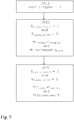
- Figure 5 shows a flow sheet diagram for the corresponding method according to an embodiment of the invention.
- a first step 501 of the method the power tool 300 is activated, i.e. the tool trigger has the value 1. In figure 4 , this happens at the position "Tool trigger" along the time axis.
- the rotational speed ⁇ motor of the motor unit 303 is increased (curve 1 in figure 4 ) as a result of the higher step-up voltage U step-up that is input to the motor unit 303.
- the output current I output and/or the torque T (curve 3 in figure 4 ) is slightly increased.
- an increased rotational speed ⁇ motor can be achieved by the present invention, which means that the nut can be quickly tightened during a phase where not too much torque is needed for the tightening.
- the rotational speed ⁇ motor of the motor unit 303 is decreased (curve 1 in figure 4 ) as a result of the lower battery voltage U battery that is input to the motor unit 303, and also due to the increased resistance of the nut because of the higher torque needed.
- the output current I output and/or the torque T (curve 3 in figure 4 ) is increased.
- an increased torque can be achieved by the present invention during the second phase where a high torque T is needed for the tightening.
- the power tool 300 is arranged for providing a high torque T during a first activation phase, and a high rotational speed ⁇ motor during a second activation phase.
- This embodiment can be particularly useful e.g. for loosening of nuts, where a high torque T is needed for the first actual loosening phase and a high speed ⁇ motor and low torque T is needed for the second phase, when the nut is already loosened.
- the battery voltage U battery is thereby provided to the electrical motor unit 303 as an output voltage U output , whereby high torque T and low speed ⁇ motor is provided.
- a low torque T and high speed ⁇ motor is provided during the second phase.
- the bypass circuit 320 is enabled and the step-up converter 310 is disabled during retardation, i.e. deceleration, of the rotational speed of the power tool.
- the electrical motor unit 303 is coupled directly to the battery unit 304 and not to the step-up converter 310.
- the rotational energy of the electrical motor unit 303 and of the spindle/shaft 102, that is set free during the retardation can be converted to electrical energy and can be utilized for charging the battery unit 304.
- the battery unit 304 includes one or more super capacitors
- the electrical energy that is extracted from the rotational energy made free during the retardation can be used for charging the super capacitors.
- the power tool of the invention can be adapted to perform any of the steps of the method of the invention.
- the different steps of the method of the invention described above can be combined or performed in any suitable order.
- the method of the invention can implemented by a computer program, having code means, which when run in a computer causes the computer to execute the steps of the method.
- the computer program is included in a computer readable medium of a computer program product.
- the computer readable medium may consist of essentially any memory, such as a ROM (Read-Only Memory), a PROM (Programmable Read-Only Memory), an EPROM (Erasable PROM), a Flash memory, an EEPROM (Electrically Erasable PROM), or a hard disk drive.
- the power tool and the methods according to the invention may be modified by those skilled in the art, as compared to the exemplary embodiments described above.
Landscapes
- Engineering & Computer Science (AREA)
- Power Engineering (AREA)
- Mechanical Engineering (AREA)
- Dc-Dc Converters (AREA)
- Portable Power Tools In General (AREA)
- Charge And Discharge Circuits For Batteries Or The Like (AREA)
Claims (33)
- Elektrowerkzeug (300), umfassend:eine Elektromotoreinheit (303), die mit einer Batterieeinheit (304) verbindbar ist;- einen Hochsetzsteller (310), der zwischen der Batterieeinheit (304) und der Elektromotoreinheit (303) anschließbar ist, der so angeordnet ist, dass er, wenn er aktiviert ist, eine Batteriespannung UBatterie die dem Hochsetzsteller (310) von der Batterieeinheit (304) geliefert wird, in eine höhere hochtransformierte Spannung UErhöhung umwandelt; UErhöhung > UBatterie; wobei die hochtransformierte Spannung UErhöhung der Elektromotoreinheit (303) als Ausgangsspannung UAusgang geliefert wird; UAusgang =UErhöhung;- eine Überbrückungsschaltung (320), die parallel zu dem Hochsetzsteller (310) angeordnet ist und, wenn sie aktiviert ist, die Batterieeinheit (304) mit der Elektromotoreinheit (303) verbindet und der Elektromotoreinheit (303) die Batteriespannung UBatterie als Ausgangsspannung UAusgang liefert; UAusgang = UBatterie; und- mindestens eine Steuereinheit (331, 332), die so angeordnet ist, dass sie den Hochsetzsteller (310) und die Überbrückungsschaltung (320) so steuert, dass die Ausgangsspannung UAusgang zwischen der Batteriespannung UBatterie und der hochtransformierten Spannung UErhöhung umgeschaltet werden kann, dadurch gekennzeichnet, dassdie Steuereinheit (331, 332) so angeordnet ist, dass sie den Hochsetzsteller (310) und die Überbrückungsschaltung (320) auf Grundlage mehrerer unterschiedlicher Parameter, für sich allein oder kombiniert verwendet, steuert, wobei die Parameter die Ausgangsspannung UAusgang, einen dem Motor gelieferten Ausgangsstrom IAusgang, eine Winkelgeschwindigkeit ωMotor der Motoreinheit (303) multipliziert mit einem von dem Werkzeug (300) gelieferten Drehmoment T; ωMotor*T, und eine der Elektromotoreinheit (303) gelieferte Ausgangsleistung PAusgang umfassen.
- Elektrowerkzeug (300) nach Anspruch 1, wobei der Hochsetzsteller (310) ein Synchron-Hochsetzsteller ist, der mindestens einen Spannungserhöhungstransistor (311), mindestens eine Induktivität (313) und mindestens einen Spannungserhöhungsschalter (312) aufweist.
- Elektrowerkzeug (300) nach Anspruch 2, wobei der Hochsetzsteller (310) eine Spannungserhöhungs-Steuerschaltungsanordnung (316, 317) aufweist, die so angeordnet ist, dass sie den mindestens einen Spannungserhöhungstransistor (311) und den mindestens einen Spannungserhöhungsschalter (312) steuert, der den Hochsetzsteller (310) mit der Elektromotoreinheit (303) verbindet, wenn er betätigt wird.
- Elektrowerkzeug (300) nach Anspruch 3, wobei die Spannungserhöhungs-Steuerschaltungsanordnung (316, 317) eine Spannungsreglerschaltungsanordnung (316) aufweist, die so angeordnet ist, dass sie die höhere Spannung UErhöhung hin zu einer Zielspannung UZiel steuert und einen Ausgang (325) des Hochsetzstellers (310) als Eingang aufweist.
- Elektrowerkzeug (300) nach einem der Ansprüche 1 bis 4, wobei die Überbrückungsschaltung (320) einen von der mindestens einen Steuereinheit (331) gesteuerten Überbrückungsschalter (321) aufweist.
- Elektrowerkzeug (300) nach Anspruch 3 oder 5, wobei der Spannungserhöhungsschalter (312), der Spannungserhöhungstransistor (311) und/oder der Überbrückungsschalter (321) umgesetzt ist bzw. sind als ein beliebiges Element in der Gruppe bestehend aus:- einem n-Kanal-MOSFET (Metall-Oxid-Halbleiter-Feldeffekttransistor) und- einem p-Kanal-MOSFET (Metall-Oxid-Halbleiter-Feldeffekttransistor).
- Elektrowerkzeug (300) nach einem der Ansprüche 1 bis 6, wobei die mindestens eine Steuereinheit (331, 332) so angeordnet ist, dass sie der Überbrückungsschaltung (320) ein Überbrückungs-Aktivierungs-/Deaktivierungssignal SÜberbrückung_an/aus liefert, wobei die Überbrückungsschaltung (320) so angeordnet ist, dass sie die Verbindung der Batterieeinheit (304) mit der Elektromotoreinheit (303) auf Grundlage des Überbrückungs-Aktivierungs-/Deaktivierungssignals SÜberbrückung_an/aus herstellt/trennt.
- Elektrowerkzeug (300) nach einem der Ansprüche 1 bis 7, wobei die mindestens eine Steuereinheit (331, 332) so angeordnet ist, dass sie dem Hochsetzsteller ein Spannungserhöhungs-Aktivierungs-/Deaktivierungssignal SErhöhung_an/aus liefert, wobei der Hochsetzsteller (310) so angeordnet ist, dass er die Spannungsumwandlung des Hochsetzstellers (310) auf Grundlage des Spannungserhöhungs-Aktivierungs-/Deaktivierungssignals SErhöhung_an/aus aktiviert/deaktiviert.
- Elektrowerkzeug (300) nach Anspruch 7 oder 8, wobei die mindestens eine Steuereinheit (331, 332) so angeordnet ist, dass sie bei dem Spannungserhöhungs-Aktivierungs-/Deaktivierungssignal SErhöhung_an/aus und/oder dem Überbrückungs-Aktivierungs-/Deaktivierungssignal SÜberbrückung_an/aus von einem Verhältnis zwischen mindestens einem der Parameter (UAusgang, IAusgang, ωMotor*T, PAusgang) Und einem Schwellenwert (USchwelle, ISchwelle, ωSchwelle*T, PSchwelle) ausgeht, der sich auf den- bzw. dieselben Parameter bezieht.
- Elektrowerkzeug (300) nach Anspruch 7 oder 8, wobei die mindestens eine Steuereinheit (331, 332) so angeordnet ist, dass sie bei dem Spannungserhöhungs-Aktivierungs-/Deaktivierungssignal SErhöhung_an/aus und/oder dem Überbrückungs-Aktivierungs-/Deaktivierungssignal SÜberbrückung_an/aus von einem Verhältnis zwischen der Ausgangsspannung UAusgang und einem Spannungsschwellenwert USchwelle ausgeht.
- Elektrowerkzeug (300) nach Anspruch 9, wobei die mindestens eine Steuereinheit (331, 332) so angeordnet ist, dass sie ein Spannungserhöhungs-Aktivierungssignal SErhöhung_an und ein Überbrückungs-Deaktivierungssignal SÜberbrückung_aus erzeugt, wenn die Ausgangsspannung UAusgang größer gleich dem Spannungsschwellenwert USchwelle ist, UAusgang ≥ USchwelle.
- Elektrowerkzeug (300) nach Anspruch 7 oder 8, wobei die mindestens eine Steuereinheit (331, 332) so angeordnet ist, dass sie bei dem Spannungserhöhungs-Aktivierungs-/Deaktivierungssignal SErhöhung_an/aus und/oder dem Überbrückungs-Aktivierungs-/Deaktivierungssignal SÜberbrückung_an/aus von einem Verhältnis zwischen einem der Motoreinheit (303) gelieferten Ausgangsstrom IAusgang und einem Stromschwellenwert ISchwelle ausgeht.
- Elektrowerkzeug (300) nach Anspruch 12, wobei die mindestens eine Steuereinheit (331, 332) so angeordnet ist, dass sie ein Spannungserhöhungs-Deaktivierungssignal SErhöhung_aus und ein Überbrückungs-Aktivierungssignal SÜberbrückung_an erzeugt, wenn der Ausgangsstrom IAusgang größer gleich dem Stromschwellenwert ISchwelle ist; IAusgang ≥ ISchwelle.
- Elektrowerkzeug (300) nach Anspruch 7 oder 8, wobei die mindestens eine Steuereinheit (331, 332) so angeordnet ist, dass sie bei dem Spannungserhöhungs-Aktivierungs-/Deaktivierungssignal SErhöhung_an/aus und/oder dem Überbrückungs-Aktivierungs-/Deaktivierungssignal SÜberbrückung_an/aus von einem Verhältnis zwischen einer Winkelgeschwindigkeit ωMotor der Motoreinheit (303) multipliziert mit einem von dem Werkzeug (300) gelieferten Drehmoment T; ωMotor*T, und einem Schwellenwert von Geschwindigkeit und Drehmoment ωTSchwelle ausgeht.
- Elektrowerkzeug (300) nach Anspruch 14, wobei die mindestens eine Steuereinheit (331, 332) so angeordnet ist, dass sie ein Spannungserhöhungs-Aktivierungssignal SErhöhung_an und ein Überbrückungs-Deaktivierungssignal SÜberbrückung_aus erzeugt, wenn die Winkelgeschwindigkeit ωMotor multipliziert mit dem Drehmoment T; ωMotor*T; geringer ist als der Schwellenwert von Geschwindigkeit und Drehmoment ωTSchwelle; ωMotor*T < ωTSchwelle.
- Elektrowerkzeug (300) nach Anspruch 7 oder 8, wobei die mindestens eine Steuereinheit (331, 332) so angeordnet ist, dass sie bei dem Spannungserhöhungs-Aktivierungs-/Deaktivierungssignal SErhöhung_an/aus und/oder dem Überbrückungs-Aktivierungs-/Deaktivierungssignal SÜberbrückung_an/aus von einem Verhältnis zwischen einer der Elektromotoreinheit (303) gelieferten Ausgangsleistung PAusgang und einem Leistungsschwellenwert PSchwelle ausgeht.
- Elektrowerkzeug (300) nach Anspruch 16, wobei die mindestens eine Steuereinheit (331, 332) so angeordnet ist, dass sie ein Spannungserhöhungs-Aktivierungssignal SErhöhung_an und ein Überbrückungs-Deaktivierungssignal SÜberbrückung_aus erzeugt, wenn die Ausgangsleistung PAusgang geringer ist als der Leistungsschwellenwert, PSchwelle; PAusgang < PSchwelle.
- Elektrowerkzeug (300) nach einem der Ansprüche 7 bis 17, wobei das Überbrückungs-Aktivierungs-/Deaktivierungssignal SÜberbrückung_an/aus und das Spannungserhöhungs-Aktivierungs-/Deaktivierungssignal SErhöhung_an/aus komplementäre Signale sind.
- Elektrowerkzeug (300) nach einem der Ansprüche 1 bis 18, wobei der Hochsetzsteller (310) zwei in jeweils entgegengesetzten Phasen betriebene Spannungserhöhungstransistorschaltungen aufweist.
- Elektrowerkzeug (300) nach einem der Ansprüche 1 bis 19, wobei der Hochsetzsteller (310) und die Überbrückungsschaltung (320) integriert in einen Körper des Elektrowerkzeugs (300) angeordnet sind, wobei der Hochsetzsteller (310) und die Überbrückungsschaltung (320) mit der Motoreinheit (303) verbunden und mit der Batterieeinheit (304) verbindbar sind.
- Elektrowerkzeug (300) nach einem der Ansprüche 1 bis 19, wobei der Hochsetzsteller (310) und die Überbrückungsschaltung (320) integriert in die und verbunden mit der Batterieeinheit (304) angeordnet sind und mit der Motoreinheit (303) verbindbar sind.
- Elektrowerkzeug (300) nach einem der Ansprüche 1 bis 19, wobei der Hochsetzsteller (310) und die Überbrückungsschaltung (320) getrennt zwischen der Batterieeinheit (304) und der Motoreinheit (303) angeordnet sind, wobei der Hochsetzsteller (310) und die Überbrückungsschaltung (320) mit der Batterieeinheit (304) und mit der Motoreinheit (303) verbindbar sind.
- Elektrowerkzeug (300) nach einem der Ansprüche 1 bis 22, wobei die Batterieeinheit (304) mindestens einen Superkondensator aufweist.
- Elektrowerkzeug (300) nach einem der Ansprüche 1 bis 23, wobei das Elektrowerkzeug (300) einen Brems-Chopper aufweist, der zum Verbrauchen von Energie angeordnet ist, die die Elektromotoreinheit (303) liefert, wenn eine Winkelgeschwindigkeit der Elektromotoreinheit (303) reduziert wird.
- Verfahren zum Liefern einer Ausgangsspannung UAusgang an eine Elektromotoreinheit (303) eines Elektrowerkzeugs (300);- Umwandeln, wenn ein Hochsetzsteller (310), der zwischen einer Batterieeinheit (304) und der Elektromotoreinheit (303) anschließbar ist, aktiviert wird, einer Batteriespannung UBatterie, die dem Hochsetzsteller (310) von der Batterieeinheit (304) geliefert wird, in eine höhere hochtransformierte Spannung UErhöhung; UErhöhung > UBatterie, und Liefern der hochtransformierten Spannung UErhöhung an die Elektromotoreinheit (303) als Ausgangsspannung UAusgang; UAusgang = UErhöhung;- Verbinden, wenn eine Überbrückungsschaltung (320), die parallel zu dem Hochsetzsteller (310) angeordnet ist, aktiviert ist, der Batterieeinheit (304) mit der Elektromotoreinheit (303), und Liefern der Batteriespannung UBatterie an die Elektromotoreinheit (303) als Ausgangsspannung UAusgang; UAusgang = UBatterie; und- Steuern, unter Verwendung von mindestens einer Steuereinheit (331, 332), des Hochsetzstellers (310) und der Überbrückungsschaltung (320) derart, dass die Ausgangsspannung UAusgang zwischen der Batteriespannung UBatterie und der hochtransformierten Spannung UErhöhung umgeschaltet werden kann, wobei die Steuerung des Hochsetzstellers (310) und der Überbrückungsschaltung (320) auf Grundlage mehrerer unterschiedlicher Parameter, für sich allein oder kombiniert verwendet, erfolgt, wobei die Parameter die Ausgangsspannung UAusgang, einen dem Motor gelieferten Ausgangsstrom IAusgang, eine Winkelgeschwindigkeit ωMotor der Motoreinheit (303) multipliziert mit einem von dem Werkzeug (300) gelieferten Drehmoment T; ωMotor*T, und eine der Elektromotoreinheit (303) gelieferte Ausgangsleistung PAusgang umfassen.
- Verfahren nach Anspruch 25, wobei die mindestens eine Steuereinheit (331, 332) den Hochsetzsteller (310) deaktiviert und die Überbrückungsschaltung (320) aktiviert, wenn zumindest einer von den mehreren unterschiedlichen Parametern (UAusgang, IAusgang, ωMotor*T, PAusgang) über einen bestimmten Schwellenwert (USchwelle, ISchwelle, ωSchwelle* T, PSchwelle) kommt oder darunter fällt.
- Verfahren nach Anspruch 25, wobei die mindestens eine Steuereinheit (331, 332) den Hochsetzsteller (310) deaktiviert und die Überbrückungsschaltung (320) aktiviert, wenn die Ausgangsspannung UAusgang niedriger ist als ein Spannungsschwellenwert USchwelle; UAusgang < USchwelle.
- Verfahren nach Anspruch 25, wobei die mindestens eine Steuereinheit (331, 332) den Hochsetzsteller (310) deaktiviert und die Überbrückungsschaltung (320) aktiviert, wenn ein Ausgangsstrom IAusgang größer gleich einem Stromschwellenwert ISchwelle ist; IAusgang ≥ ISchwelle.
- Verfahren nach Anspruch 25, wobei die mindestens eine Steuereinheit (331, 332) den Hochsetzsteller (310) aktiviert und die Überbrückungsschaltung (320) deaktiviert, wenn eine Winkelgeschwindigkeit ωMotor der Motoreinheit (303) multipliziert mit einem von dem Elektrowerkzeug (300) gelieferten Drehmoment T; ωMotor*T, geringer ist als der Schwellenwert von Geschwindigkeit und Drehmoment ωTSchwelle; ωMotor*T < ωTSchwelle.
- Verfahren nach Anspruch 25, wobei die mindestens eine Steuereinheit (331, 332) den Hochsetzsteller (310) aktiviert und die Überbrückungsschaltung (320) deaktiviert, wenn eine der Elektromotoreinheit (303) gelieferte Ausgangsleistung PAusgang niedriger ist als ein Leistungsschwellenwert PSchwelle; PAusgang < PSchwelle.
- Verfahren nach einem der Ansprüche 25 bis 30, wobei eine Betätigung des Elektrowerkzeugs (300) Folgendes umfasst:- Aktivieren des Hochsetzstellers (310) und Deaktivieren der Überbrückungsschaltung (320) während einer ersten Phase der Betätigung, wodurch der Elektromotoreinheit (303) die hochtransformierte Spannung UErhöhung als Ausgangsspannung UAusgang geliefert wird; UAusgang = UErhöhung; wodurch eine Winkelgeschwindigkeit ωMotor der Motoreinheit (303) infolge der höheren hochtransformierten Spannung UErhöhung erhöht wird;- Aktivieren der Überbrückungsschaltung (320) und Deaktivieren des Hochsetzstellers (310) während einer zweiten Phase der Betätigung, wodurch der Elektromotoreinheit (303) die Batteriespannung UBatterie als Ausgangsspannung UAusgang geliefert wird; UAusgang = UBatterie; wodurch die Winkelgeschwindigkeit ωMotor der Motoreinheit (303) infolge der niedrigeren Batteriespannung UBatterie vermindert wird.
- Computerprogramm, gekennzeichnet durch ein Codemittel, das bei Ausführung auf einem Computer bewirkt, dass das Elektrowerkzeug nach Anspruch 1 das Verfahren nach einem der Ansprüche 25 bis 31 ausführt.
- Computerprogrammprodukt, das ein computerlesbares Medium und ein Computerprogramm nach Anspruch 32 aufweist, wobei das Computerprogramm in dem computerlesbaren Medium enthalten ist.
Applications Claiming Priority (2)
| Application Number | Priority Date | Filing Date | Title |
|---|---|---|---|
| SE1350546 | 2013-05-03 | ||
| PCT/EP2014/058835 WO2014177618A2 (en) | 2013-05-03 | 2014-04-30 | Power tool with step-up converter |
Publications (2)
| Publication Number | Publication Date |
|---|---|
| EP2991807A2 EP2991807A2 (de) | 2016-03-09 |
| EP2991807B1 true EP2991807B1 (de) | 2017-08-02 |
Family
ID=50628824
Family Applications (1)
| Application Number | Title | Priority Date | Filing Date |
|---|---|---|---|
| EP14720607.2A Active EP2991807B1 (de) | 2013-05-03 | 2014-04-30 | Elektrowerkzeug mit hochsetzsteller |
Country Status (5)
| Country | Link |
|---|---|
| US (1) | US10498151B2 (de) |
| EP (1) | EP2991807B1 (de) |
| JP (1) | JP6356225B2 (de) |
| CN (1) | CN105189049B (de) |
| WO (1) | WO2014177618A2 (de) |
Families Citing this family (7)
| Publication number | Priority date | Publication date | Assignee | Title |
|---|---|---|---|---|
| DE102013200602B4 (de) * | 2013-01-16 | 2023-07-13 | Robert Bosch Gmbh | Elektrowerkzeug mit verbesserter Bedienbarkeit |
| JP6152241B2 (ja) * | 2014-04-23 | 2017-06-21 | レノボ・シンガポール・プライベート・リミテッド | 電力システム、携帯式電子機器および電力の供給方法 |
| EP3435474A1 (de) * | 2017-07-27 | 2019-01-30 | HILTI Aktiengesellschaft | Bypass-schaltung an einem akkumulator |
| US11469661B2 (en) * | 2019-10-25 | 2022-10-11 | Cirrus Logic, Inc. | Multiphase inductive boost converter with multiple operational phases |
| WO2021247827A1 (en) * | 2020-06-04 | 2021-12-09 | Milwaukee Electric Tool Corporation | Power supply with high and low power operating modes |
| US20220190767A1 (en) * | 2020-12-11 | 2022-06-16 | Snap-On Incorporated | Tool brownout management |
| TWI817740B (zh) * | 2022-09-27 | 2023-10-01 | 宏碁股份有限公司 | 馬達控制器及其控制方法 |
Family Cites Families (15)
| Publication number | Priority date | Publication date | Assignee | Title |
|---|---|---|---|---|
| JP3478110B2 (ja) * | 1998-01-27 | 2003-12-15 | 松下電工株式会社 | モータ駆動用制御回路 |
| CN1305260A (zh) * | 2001-01-21 | 2001-07-25 | 顺德市力威电器实业有限公司 | 脉宽调整式直流变交流高效逆变电源 |
| TW579289B (en) * | 2001-05-23 | 2004-03-11 | Toshiba Tec Kk | Vacuum cleaner |
| JP2003250737A (ja) * | 2001-12-25 | 2003-09-09 | Toshiba Tec Corp | 電気掃除機 |
| JP3960931B2 (ja) * | 2003-02-27 | 2007-08-15 | シャープ株式会社 | 電池駆動装置及び電源供給方法 |
| CN1549419A (zh) * | 2003-05-08 | 2004-11-24 | 友昕科技股份有限公司 | 用以产生各种类型脉冲的电源模块 |
| JP4593973B2 (ja) * | 2004-05-26 | 2010-12-08 | トヨタ自動車株式会社 | モータ駆動装置 |
| JP4070750B2 (ja) * | 2004-06-21 | 2008-04-02 | シャープ株式会社 | 電池駆動装置 |
| US20060119322A1 (en) * | 2004-12-04 | 2006-06-08 | Hossein Maleki | Battery pack with temperature activated boost |
| JP5029337B2 (ja) * | 2007-12-12 | 2012-09-19 | 株式会社ニコン | 電源回路 |
| US7977816B2 (en) | 2008-12-19 | 2011-07-12 | Silicon Laboratories Inc. | DC/DC boost converter with bypass feature |
| JP5408535B2 (ja) * | 2009-07-10 | 2014-02-05 | 日立工機株式会社 | 電動工具 |
| JP5476177B2 (ja) * | 2010-03-26 | 2014-04-23 | パナソニック株式会社 | 電動工具 |
| JP2014036521A (ja) * | 2012-08-09 | 2014-02-24 | Panasonic Corp | アダプタ及び電動工具 |
| JP2014148019A (ja) * | 2013-02-01 | 2014-08-21 | Makita Corp | 電動作業機 |
-
2014
- 2014-04-30 EP EP14720607.2A patent/EP2991807B1/de active Active
- 2014-04-30 WO PCT/EP2014/058835 patent/WO2014177618A2/en active Application Filing
- 2014-04-30 CN CN201480025047.1A patent/CN105189049B/zh active Active
- 2014-04-30 JP JP2016511056A patent/JP6356225B2/ja active Active
- 2014-04-30 US US14/783,371 patent/US10498151B2/en active Active
Non-Patent Citations (1)
| Title |
|---|
| None * |
Also Published As
| Publication number | Publication date |
|---|---|
| WO2014177618A2 (en) | 2014-11-06 |
| CN105189049B (zh) | 2017-09-29 |
| CN105189049A (zh) | 2015-12-23 |
| JP2016516605A (ja) | 2016-06-09 |
| EP2991807A2 (de) | 2016-03-09 |
| JP6356225B2 (ja) | 2018-07-11 |
| WO2014177618A3 (en) | 2015-02-19 |
| US20160049817A1 (en) | 2016-02-18 |
| US10498151B2 (en) | 2019-12-03 |
Similar Documents
| Publication | Publication Date | Title |
|---|---|---|
| EP2991807B1 (de) | Elektrowerkzeug mit hochsetzsteller | |
| EP3252938B1 (de) | Vorladungsvorrichtung für stromumwandlungssystem | |
| JP5433608B2 (ja) | 電力変換装置 | |
| US20160380563A1 (en) | Power conversion control apparatus | |
| JP2014069252A (ja) | 電動工具 | |
| EP3138725B1 (de) | Doppelquellen-mehrfachmodus-fahrzeugstromversorgung | |
| EP1862348A1 (de) | Motorsteuervorrichtung und Motorantriebssystem in einem Fahrzeug | |
| RU2657103C2 (ru) | Приводной блок для управления двигателем | |
| US10848073B2 (en) | Motor drive apparatus equipped with discharge circuit of capacitor of DC link | |
| JP6185860B2 (ja) | 双方向コンバータ | |
| JP6496371B2 (ja) | Pwmコンバータの昇圧率が制御されるモータ駆動装置 | |
| KR101835742B1 (ko) | 이중 배터리 패키지 및 이의 작동방법 | |
| JP6426775B2 (ja) | モータ駆動装置 | |
| JP2014110666A (ja) | 放電制御システム及び放電装置 | |
| JP2010051111A (ja) | モータ駆動装置 | |
| US8390260B2 (en) | Power supply for negative voltage load | |
| US20210083588A1 (en) | Power Conversion Device | |
| US20190337474A1 (en) | In-vehicle power supply device | |
| KR101686864B1 (ko) | 이중 배터리 패키지 | |
| WO2016190031A1 (ja) | 電力変換装置及びこれを用いた電源システム | |
| WO2009043373A1 (en) | A drive unit for an electric motor | |
| JP7420032B2 (ja) | 過電流検出装置 | |
| JP5508870B2 (ja) | モータ制御装置 | |
| JP2023062621A (ja) | 電力変換装置 | |
| JP2019197978A (ja) | 抑制回路 |
Legal Events
| Date | Code | Title | Description |
|---|---|---|---|
| PUAI | Public reference made under article 153(3) epc to a published international application that has entered the european phase |
Free format text: ORIGINAL CODE: 0009012 |
|
| 17P | Request for examination filed |
Effective date: 20151113 |
|
| AK | Designated contracting states |
Kind code of ref document: A2 Designated state(s): AL AT BE BG CH CY CZ DE DK EE ES FI FR GB GR HR HU IE IS IT LI LT LU LV MC MK MT NL NO PL PT RO RS SE SI SK SM TR |
|
| AX | Request for extension of the european patent |
Extension state: BA ME |
|
| DAX | Request for extension of the european patent (deleted) | ||
| GRAP | Despatch of communication of intention to grant a patent |
Free format text: ORIGINAL CODE: EPIDOSNIGR1 |
|
| INTG | Intention to grant announced |
Effective date: 20170418 |
|
| GRAS | Grant fee paid |
Free format text: ORIGINAL CODE: EPIDOSNIGR3 |
|
| GRAA | (expected) grant |
Free format text: ORIGINAL CODE: 0009210 |
|
| AK | Designated contracting states |
Kind code of ref document: B1 Designated state(s): AL AT BE BG CH CY CZ DE DK EE ES FI FR GB GR HR HU IE IS IT LI LT LU LV MC MK MT NL NO PL PT RO RS SE SI SK SM TR |
|
| REG | Reference to a national code |
Ref country code: CH Ref legal event code: EP Ref country code: AT Ref legal event code: REF Ref document number: 913936 Country of ref document: AT Kind code of ref document: T Effective date: 20170815 |
|
| REG | Reference to a national code |
Ref country code: IE Ref legal event code: FG4D |
|
| REG | Reference to a national code |
Ref country code: DE Ref legal event code: R096 Ref document number: 602014012550 Country of ref document: DE |
|
| REG | Reference to a national code |
Ref country code: NL Ref legal event code: MP Effective date: 20170802 |
|
| REG | Reference to a national code |
Ref country code: AT Ref legal event code: MK05 Ref document number: 913936 Country of ref document: AT Kind code of ref document: T Effective date: 20170802 |
|
| REG | Reference to a national code |
Ref country code: LT Ref legal event code: MG4D |
|
| PG25 | Lapsed in a contracting state [announced via postgrant information from national office to epo] |
Ref country code: SE Free format text: LAPSE BECAUSE OF FAILURE TO SUBMIT A TRANSLATION OF THE DESCRIPTION OR TO PAY THE FEE WITHIN THE PRESCRIBED TIME-LIMIT Effective date: 20170802 Ref country code: LT Free format text: LAPSE BECAUSE OF FAILURE TO SUBMIT A TRANSLATION OF THE DESCRIPTION OR TO PAY THE FEE WITHIN THE PRESCRIBED TIME-LIMIT Effective date: 20170802 Ref country code: HR Free format text: LAPSE BECAUSE OF FAILURE TO SUBMIT A TRANSLATION OF THE DESCRIPTION OR TO PAY THE FEE WITHIN THE PRESCRIBED TIME-LIMIT Effective date: 20170802 Ref country code: AT Free format text: LAPSE BECAUSE OF FAILURE TO SUBMIT A TRANSLATION OF THE DESCRIPTION OR TO PAY THE FEE WITHIN THE PRESCRIBED TIME-LIMIT Effective date: 20170802 Ref country code: NL Free format text: LAPSE BECAUSE OF FAILURE TO SUBMIT A TRANSLATION OF THE DESCRIPTION OR TO PAY THE FEE WITHIN THE PRESCRIBED TIME-LIMIT Effective date: 20170802 Ref country code: FI Free format text: LAPSE BECAUSE OF FAILURE TO SUBMIT A TRANSLATION OF THE DESCRIPTION OR TO PAY THE FEE WITHIN THE PRESCRIBED TIME-LIMIT Effective date: 20170802 Ref country code: NO Free format text: LAPSE BECAUSE OF FAILURE TO SUBMIT A TRANSLATION OF THE DESCRIPTION OR TO PAY THE FEE WITHIN THE PRESCRIBED TIME-LIMIT Effective date: 20171102 |
|
| PG25 | Lapsed in a contracting state [announced via postgrant information from national office to epo] |
Ref country code: IS Free format text: LAPSE BECAUSE OF FAILURE TO SUBMIT A TRANSLATION OF THE DESCRIPTION OR TO PAY THE FEE WITHIN THE PRESCRIBED TIME-LIMIT Effective date: 20171202 Ref country code: PL Free format text: LAPSE BECAUSE OF FAILURE TO SUBMIT A TRANSLATION OF THE DESCRIPTION OR TO PAY THE FEE WITHIN THE PRESCRIBED TIME-LIMIT Effective date: 20170802 Ref country code: ES Free format text: LAPSE BECAUSE OF FAILURE TO SUBMIT A TRANSLATION OF THE DESCRIPTION OR TO PAY THE FEE WITHIN THE PRESCRIBED TIME-LIMIT Effective date: 20170802 Ref country code: RS Free format text: LAPSE BECAUSE OF FAILURE TO SUBMIT A TRANSLATION OF THE DESCRIPTION OR TO PAY THE FEE WITHIN THE PRESCRIBED TIME-LIMIT Effective date: 20170802 Ref country code: GR Free format text: LAPSE BECAUSE OF FAILURE TO SUBMIT A TRANSLATION OF THE DESCRIPTION OR TO PAY THE FEE WITHIN THE PRESCRIBED TIME-LIMIT Effective date: 20171103 Ref country code: LV Free format text: LAPSE BECAUSE OF FAILURE TO SUBMIT A TRANSLATION OF THE DESCRIPTION OR TO PAY THE FEE WITHIN THE PRESCRIBED TIME-LIMIT Effective date: 20170802 Ref country code: BG Free format text: LAPSE BECAUSE OF FAILURE TO SUBMIT A TRANSLATION OF THE DESCRIPTION OR TO PAY THE FEE WITHIN THE PRESCRIBED TIME-LIMIT Effective date: 20171102 |
|
| REG | Reference to a national code |
Ref country code: FR Ref legal event code: PLFP Year of fee payment: 5 |
|
| PG25 | Lapsed in a contracting state [announced via postgrant information from national office to epo] |
Ref country code: CZ Free format text: LAPSE BECAUSE OF FAILURE TO SUBMIT A TRANSLATION OF THE DESCRIPTION OR TO PAY THE FEE WITHIN THE PRESCRIBED TIME-LIMIT Effective date: 20170802 Ref country code: RO Free format text: LAPSE BECAUSE OF FAILURE TO SUBMIT A TRANSLATION OF THE DESCRIPTION OR TO PAY THE FEE WITHIN THE PRESCRIBED TIME-LIMIT Effective date: 20170802 Ref country code: DK Free format text: LAPSE BECAUSE OF FAILURE TO SUBMIT A TRANSLATION OF THE DESCRIPTION OR TO PAY THE FEE WITHIN THE PRESCRIBED TIME-LIMIT Effective date: 20170802 |
|
| REG | Reference to a national code |
Ref country code: DE Ref legal event code: R097 Ref document number: 602014012550 Country of ref document: DE |
|
| PG25 | Lapsed in a contracting state [announced via postgrant information from national office to epo] |
Ref country code: EE Free format text: LAPSE BECAUSE OF FAILURE TO SUBMIT A TRANSLATION OF THE DESCRIPTION OR TO PAY THE FEE WITHIN THE PRESCRIBED TIME-LIMIT Effective date: 20170802 Ref country code: SM Free format text: LAPSE BECAUSE OF FAILURE TO SUBMIT A TRANSLATION OF THE DESCRIPTION OR TO PAY THE FEE WITHIN THE PRESCRIBED TIME-LIMIT Effective date: 20170802 Ref country code: SK Free format text: LAPSE BECAUSE OF FAILURE TO SUBMIT A TRANSLATION OF THE DESCRIPTION OR TO PAY THE FEE WITHIN THE PRESCRIBED TIME-LIMIT Effective date: 20170802 Ref country code: IT Free format text: LAPSE BECAUSE OF FAILURE TO SUBMIT A TRANSLATION OF THE DESCRIPTION OR TO PAY THE FEE WITHIN THE PRESCRIBED TIME-LIMIT Effective date: 20170802 |
|
| PLBE | No opposition filed within time limit |
Free format text: ORIGINAL CODE: 0009261 |
|
| STAA | Information on the status of an ep patent application or granted ep patent |
Free format text: STATUS: NO OPPOSITION FILED WITHIN TIME LIMIT |
|
| 26N | No opposition filed |
Effective date: 20180503 |
|
| PG25 | Lapsed in a contracting state [announced via postgrant information from national office to epo] |
Ref country code: SI Free format text: LAPSE BECAUSE OF FAILURE TO SUBMIT A TRANSLATION OF THE DESCRIPTION OR TO PAY THE FEE WITHIN THE PRESCRIBED TIME-LIMIT Effective date: 20170802 |
|
| PG25 | Lapsed in a contracting state [announced via postgrant information from national office to epo] |
Ref country code: MC Free format text: LAPSE BECAUSE OF FAILURE TO SUBMIT A TRANSLATION OF THE DESCRIPTION OR TO PAY THE FEE WITHIN THE PRESCRIBED TIME-LIMIT Effective date: 20170802 |
|
| REG | Reference to a national code |
Ref country code: CH Ref legal event code: PL |
|
| REG | Reference to a national code |
Ref country code: BE Ref legal event code: MM Effective date: 20180430 |
|
| REG | Reference to a national code |
Ref country code: IE Ref legal event code: MM4A |
|
| PG25 | Lapsed in a contracting state [announced via postgrant information from national office to epo] |
Ref country code: LU Free format text: LAPSE BECAUSE OF NON-PAYMENT OF DUE FEES Effective date: 20180430 |
|
| PG25 | Lapsed in a contracting state [announced via postgrant information from national office to epo] |
Ref country code: BE Free format text: LAPSE BECAUSE OF NON-PAYMENT OF DUE FEES Effective date: 20180430 Ref country code: CH Free format text: LAPSE BECAUSE OF NON-PAYMENT OF DUE FEES Effective date: 20180430 Ref country code: LI Free format text: LAPSE BECAUSE OF NON-PAYMENT OF DUE FEES Effective date: 20180430 |
|
| PG25 | Lapsed in a contracting state [announced via postgrant information from national office to epo] |
Ref country code: IE Free format text: LAPSE BECAUSE OF NON-PAYMENT OF DUE FEES Effective date: 20180430 |
|
| PG25 | Lapsed in a contracting state [announced via postgrant information from national office to epo] |
Ref country code: MT Free format text: LAPSE BECAUSE OF NON-PAYMENT OF DUE FEES Effective date: 20180430 |
|
| PG25 | Lapsed in a contracting state [announced via postgrant information from national office to epo] |
Ref country code: TR Free format text: LAPSE BECAUSE OF FAILURE TO SUBMIT A TRANSLATION OF THE DESCRIPTION OR TO PAY THE FEE WITHIN THE PRESCRIBED TIME-LIMIT Effective date: 20170802 |
|
| PG25 | Lapsed in a contracting state [announced via postgrant information from national office to epo] |
Ref country code: PT Free format text: LAPSE BECAUSE OF FAILURE TO SUBMIT A TRANSLATION OF THE DESCRIPTION OR TO PAY THE FEE WITHIN THE PRESCRIBED TIME-LIMIT Effective date: 20170802 |
|
| PG25 | Lapsed in a contracting state [announced via postgrant information from national office to epo] |
Ref country code: MK Free format text: LAPSE BECAUSE OF NON-PAYMENT OF DUE FEES Effective date: 20170802 Ref country code: HU Free format text: LAPSE BECAUSE OF FAILURE TO SUBMIT A TRANSLATION OF THE DESCRIPTION OR TO PAY THE FEE WITHIN THE PRESCRIBED TIME-LIMIT; INVALID AB INITIO Effective date: 20140430 Ref country code: CY Free format text: LAPSE BECAUSE OF FAILURE TO SUBMIT A TRANSLATION OF THE DESCRIPTION OR TO PAY THE FEE WITHIN THE PRESCRIBED TIME-LIMIT Effective date: 20170802 |
|
| PG25 | Lapsed in a contracting state [announced via postgrant information from national office to epo] |
Ref country code: AL Free format text: LAPSE BECAUSE OF FAILURE TO SUBMIT A TRANSLATION OF THE DESCRIPTION OR TO PAY THE FEE WITHIN THE PRESCRIBED TIME-LIMIT Effective date: 20170802 |
|
| P01 | Opt-out of the competence of the unified patent court (upc) registered |
Effective date: 20230525 |
|
| PGFP | Annual fee paid to national office [announced via postgrant information from national office to epo] |
Ref country code: FR Payment date: 20230425 Year of fee payment: 10 Ref country code: DE Payment date: 20230427 Year of fee payment: 10 |
|
| PGFP | Annual fee paid to national office [announced via postgrant information from national office to epo] |
Ref country code: GB Payment date: 20230427 Year of fee payment: 10 |