EP2989376B1 - Beleuchtungsanordnung mit länglichem leuchtengehäuse - Google Patents
Beleuchtungsanordnung mit länglichem leuchtengehäuse Download PDFInfo
- Publication number
- EP2989376B1 EP2989376B1 EP14722143.6A EP14722143A EP2989376B1 EP 2989376 B1 EP2989376 B1 EP 2989376B1 EP 14722143 A EP14722143 A EP 14722143A EP 2989376 B1 EP2989376 B1 EP 2989376B1
- Authority
- EP
- European Patent Office
- Prior art keywords
- light
- light sources
- lighting arrangement
- group
- arrangement according
- Prior art date
- Legal status (The legal status is an assumption and is not a legal conclusion. Google has not performed a legal analysis and makes no representation as to the accuracy of the status listed.)
- Active
Links
- 238000000149 argon plasma sintering Methods 0.000 description 2
- 238000000265 homogenisation Methods 0.000 description 2
- 230000002411 adverse Effects 0.000 description 1
- 230000001419 dependent effect Effects 0.000 description 1
- 238000011161 development Methods 0.000 description 1
- 230000018109 developmental process Effects 0.000 description 1
- 230000003287 optical effect Effects 0.000 description 1
Images
Classifications
-
- G—PHYSICS
- G08—SIGNALLING
- G08B—SIGNALLING OR CALLING SYSTEMS; ORDER TELEGRAPHS; ALARM SYSTEMS
- G08B7/00—Signalling systems according to more than one of groups G08B3/00 - G08B6/00; Personal calling systems according to more than one of groups G08B3/00 - G08B6/00
- G08B7/06—Signalling systems according to more than one of groups G08B3/00 - G08B6/00; Personal calling systems according to more than one of groups G08B3/00 - G08B6/00 using electric transmission, e.g. involving audible and visible signalling through the use of sound and light sources
- G08B7/066—Signalling systems according to more than one of groups G08B3/00 - G08B6/00; Personal calling systems according to more than one of groups G08B3/00 - G08B6/00 using electric transmission, e.g. involving audible and visible signalling through the use of sound and light sources guiding along a path, e.g. evacuation path lighting strip
-
- F—MECHANICAL ENGINEERING; LIGHTING; HEATING; WEAPONS; BLASTING
- F21—LIGHTING
- F21S—NON-PORTABLE LIGHTING DEVICES; SYSTEMS THEREOF; VEHICLE LIGHTING DEVICES SPECIALLY ADAPTED FOR VEHICLE EXTERIORS
- F21S4/00—Lighting devices or systems using a string or strip of light sources
- F21S4/20—Lighting devices or systems using a string or strip of light sources with light sources held by or within elongate supports
- F21S4/28—Lighting devices or systems using a string or strip of light sources with light sources held by or within elongate supports rigid, e.g. LED bars
-
- F—MECHANICAL ENGINEERING; LIGHTING; HEATING; WEAPONS; BLASTING
- F21—LIGHTING
- F21V—FUNCTIONAL FEATURES OR DETAILS OF LIGHTING DEVICES OR SYSTEMS THEREOF; STRUCTURAL COMBINATIONS OF LIGHTING DEVICES WITH OTHER ARTICLES, NOT OTHERWISE PROVIDED FOR
- F21V23/00—Arrangement of electric circuit elements in or on lighting devices
- F21V23/04—Arrangement of electric circuit elements in or on lighting devices the elements being switches
- F21V23/0442—Arrangement of electric circuit elements in or on lighting devices the elements being switches activated by means of a sensor, e.g. motion or photodetectors
- F21V23/0471—Arrangement of electric circuit elements in or on lighting devices the elements being switches activated by means of a sensor, e.g. motion or photodetectors the sensor detecting the proximity, the presence or the movement of an object or a person
-
- F—MECHANICAL ENGINEERING; LIGHTING; HEATING; WEAPONS; BLASTING
- F21—LIGHTING
- F21S—NON-PORTABLE LIGHTING DEVICES; SYSTEMS THEREOF; VEHICLE LIGHTING DEVICES SPECIALLY ADAPTED FOR VEHICLE EXTERIORS
- F21S8/00—Lighting devices intended for fixed installation
- F21S8/02—Lighting devices intended for fixed installation of recess-mounted type, e.g. downlighters
- F21S8/026—Lighting devices intended for fixed installation of recess-mounted type, e.g. downlighters intended to be recessed in a ceiling or like overhead structure, e.g. suspended ceiling
-
- F—MECHANICAL ENGINEERING; LIGHTING; HEATING; WEAPONS; BLASTING
- F21—LIGHTING
- F21Y—INDEXING SCHEME ASSOCIATED WITH SUBCLASSES F21K, F21L, F21S and F21V, RELATING TO THE FORM OR THE KIND OF THE LIGHT SOURCES OR OF THE COLOUR OF THE LIGHT EMITTED
- F21Y2103/00—Elongate light sources, e.g. fluorescent tubes
- F21Y2103/10—Elongate light sources, e.g. fluorescent tubes comprising a linear array of point-like light-generating elements
-
- F—MECHANICAL ENGINEERING; LIGHTING; HEATING; WEAPONS; BLASTING
- F21—LIGHTING
- F21Y—INDEXING SCHEME ASSOCIATED WITH SUBCLASSES F21K, F21L, F21S and F21V, RELATING TO THE FORM OR THE KIND OF THE LIGHT SOURCES OR OF THE COLOUR OF THE LIGHT EMITTED
- F21Y2113/00—Combination of light sources
- F21Y2113/10—Combination of light sources of different colours
- F21Y2113/13—Combination of light sources of different colours comprising an assembly of point-like light sources
-
- F—MECHANICAL ENGINEERING; LIGHTING; HEATING; WEAPONS; BLASTING
- F21—LIGHTING
- F21Y—INDEXING SCHEME ASSOCIATED WITH SUBCLASSES F21K, F21L, F21S and F21V, RELATING TO THE FORM OR THE KIND OF THE LIGHT SOURCES OR OF THE COLOUR OF THE LIGHT EMITTED
- F21Y2115/00—Light-generating elements of semiconductor light sources
- F21Y2115/10—Light-emitting diodes [LED]
Definitions
- the present invention relates to a lighting arrangement according to the preamble of claim 1, which has an elongated luminaire housing which is closed on one light exit side by a light-emitting element, light sources being provided within the luminaire housing and arranged substantially uniformly distributed over the entire length of the lighting arrangement are.
- a lighting arrangement is, for example, from EP 0 609 170 A1 known.
- Luminaires that are part of larger systems, e.g. for illuminating buildings or building complexes, fulfill different tasks.
- luminaires are primarily used for room lighting, for example to illuminate certain rooms or areas, their workplaces or the like in accordance with the needs of the people inside.
- escape sign luminaires of this type serve to indicate an escape route in order to enable people to leave the building safely in the event of an emergency.
- escape sign luminaires usually have a pictogram which represents the direction of the escape route and is illuminated with the aid of light sources.
- the present invention is therefore based on the task of specifying a novel concept for realizing a luminaire or a lighting arrangement, which makes it possible to combine different tasks of lighting technology in a common arrangement.
- a novel concept for realizing a luminaire or a lighting arrangement which makes it possible to combine different tasks of lighting technology in a common arrangement.
- as few separate units as possible should be installed in a room, which despite everything can then perform different tasks.
- the solution according to the invention is based on the idea of using a luminaire with an elongated luminaire housing and first light sources arranged therein, which are used for room lighting and are arranged essentially uniformly distributed over the entire length of the lighting arrangement.
- These light sources preferably ensure that a light emission element, which closes the lamp housing, is brightened as homogeneously or uniformly as possible when the light sources are in operation.
- at least one further light source and one sensor are arranged within the lamp housing in areas between the first light sources, this further light source using the light exit element of the lamp in the same way for emitting light or the sensor detecting data through the light emitting element for the desired lighting control ,
- a lighting arrangement with an elongated luminaire housing is proposed, which is closed off on one light exit side by a light exit element, a first group of similar light sources being provided within the luminaire housing, which are essentially: are evenly distributed over the entire length of the lighting arrangement.
- a further light source and a sensor are arranged, which uses the emitting element for emitting light or detects sensor data through the light emitting element.
- the lighting arrangement according to the invention thus results in the appearance of a single elongated luminaire which can be used in a conventional manner for room lighting or for lighting aisles or the like.
- additional light sources and a sensor are now integrated in the luminaire, which use the light emitting element in the same way and can be used, for example, to represent an escape route or to record data for automated lighting control.
- these additional components do not impair the appearance of the entire arrangement, since they are not recognizable from the outside during normal operation and - in the case of the additional light sources - only in the event that their use is actually required, a light signal recognizable for an observer or provide appropriate information.
- a plurality of light sources, which form a second group of light sources, which can be controlled separately from the first group, are preferably arranged in intermediate regions between the light sources of the first group.
- the first group is preferably used for general room lighting.
- the sources are usually white light. They are preferably essentially point-shaped light sources, that is to say in particular LEDs, particularly preferably white light LEDs.
- the second group of light sources is then intended to represent the direction of an escape route, it is preferably colored light sources, in particular light sources which emit green light, for example.
- the direction of an escape route can then be indicated, if necessary, by means of a corresponding control of these colored light sources, which may be coordinated with one another, which is done, for example, by the display of a green red dot moving in the direction of the escape route.
- the light exit element of FIG Lighting arrangement used, which is intended for general light emission.
- the light emission element is preferably designed in such a way that it brings about a certain homogenization of the light emission, which can be realized in that the light emission element contains light-scattering material. With a similar control of the light sources of the first group, a uniform, uniform light emission is achieved over the entire length of the lamp.
- the solution according to the invention thus creates a lighting arrangement which has a simple appearance, namely that of a conventional elongated luminaire or a strip of light, in spite of which different tasks can be performed for the purpose of lighting.
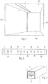
- an elongated space 100 is shown.
- it can be a corridor in a building that is to be illuminated along its length.
- the lighting arrangement according to the invention generally provided with reference number 1, is provided, which is located on the ceiling 101 of the room or hallway 100 is arranged.
- the lighting arrangement 1 it would also be conceivable to arrange the lighting arrangement 1 on one of the side walls 102, 103.
- the lighting arrangement 1 is designed as a recessed luminaire, that is to say it is arranged in an elongated opening within the ceiling 101 and is preferably designed in such a way that its light exit disc 5 is flush with the ceiling 101.
- an elongated so-called light line which preferably extends over the entire length of the room 100, is realized in this way, which has an extremely attractive appearance.
- the generation of such light lines is already known in principle and is carried out with the aid of so-called slotlight lamps.
- the structure of the lighting arrangement according to the invention can be closer to the representations of the Figures 2 and 3 are taken from Figure 3 shows a sectional view of the lighting arrangement 1 and Figure 2 from the bottom shows the arrangement of the light sources located therein and possibly other sensors.
- the lighting arrangement 1 has an elongated support element in the form of a U-shaped support rail 2 which is open at the bottom.
- This mounting rail 2 is arranged within the mounting opening of the ceiling 101 of the room 100 to be illuminated and serves as a central support element for the lighting arrangement 1 Figure 3 shown operating devices 7 arranged for the power supply of the light sources.
- power supply lines for supplying the light sources run in the longitudinal direction.
- the mounting rail 2 is fastened in the ceiling opening by means of mounting elements (not shown), and as already mentioned the arrangement is selected such that the elongated light outlet element 5 located on the underside of the mounting rail 2 is as flush as possible with the underside of the ceiling.
- the light exit element 5 itself is formed by one or more elongated disks which are attached to the underside of the mounting rail 2.
- the light sources responsible for the light emission are then also arranged within the mounting rail 2.
- a first group of light sources 10 is initially provided, which - as in FIG Figure 3 shown - distributed as evenly as possible over the entire Length of the lighting arrangement 1 are arranged away.
- These first light sources 10 are responsible for general lighting and are intended to form the light line already mentioned above.
- the light sources are white light, which are preferably formed by white light LEDs. It is important for the concept of the present invention that the light sources are not elongated and extend continuously over the entire length of the lighting arrangement 1. Instead, essentially point-shaped light sources are provided, which form free areas in between, which - as will be explained in more detail below - can be used to arrange further components.
- the light sources 10 are not recognizable as individual light sources. This can be done, for example, by assigning corresponding optical elements to the white light LEDs 10, which bring about a very strong distribution in the longitudinal direction of the lighting arrangement 1.
- the light emitting element 5 itself is designed such that it ensures a corresponding homogenization of the light output. Corresponding light-scattering materials can be used for this, from which the light-emitting element 5 is made or which are part of the light-emitting element 5.
- a classic slotlight luminaire is in turn first formed, which enables the realization of light lines.
- additional components are now arranged within the carrier element 2, which are used to record sensor data, for example for automated control of the lighting or for an additional light emission.
- a sensor 15 and on the other hand further light sources 20 from a second group which are arranged, for example, in the end region of the lighting arrangement 1.
- the sensor 15 can, for example, be a brightness sensor or a presence sensor.
- the information recorded by the sensor 15 can then be used for the automated control of, for example, the light sources of the first group 10, it being possible in the usual way to adjust the brightness of the light sources 10 or the light sources 10 when the presence of a person is detected be activated at all. If, however, it is a brightness sensor, they can Corresponding information for setting the brightness for the light sources 10 can be used in order to enable optimal energy-efficient lighting using the ambient light.
- the light sources 20 of the second group serve to represent an escape route.
- LEDs are preferably used for this purpose, which can be controlled independently of the light sources 10 of the first group, since the representation of an escape route should only take place when necessary.
- both the sensor 15 and the light sources 20 of the second group are arranged in the same way within the lighting arrangement 1 and in particular also use the light emission element 5 in the same way as the light sources of the first group 10. That is, the light sources 20 of the second group also emit light via the light emitting element 5 if necessary.
- the sensor 15, on the other hand, is designed to record sensor data through the light-emitting element 5, that is to say, for example, to record the brightness present outside the lamp or to detect the presence of people. Both the sensor 15 and the light sources of the second group 20 are therefore not arranged outside the lighting arrangement 1 and need not be part of separate elements which would impair the overall appearance of the arrangement.
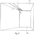
- the function of the light sources 20 of the second group for representing an escape route is shown schematically in FIG Figure 4 recognizable.
- the aid of the light sources 10 of the first group With the aid of the light sources 10 of the first group, a uniformly bright light line that extends over the entire length of the room 100 is generated.
- the direction of an escape route is to be displayed, which according to the present invention takes place with the aid of the light sources 20 of the second group such that a green light traveling in the direction of the escape route is displayed.
- the lighting arrangement according to the invention can therefore also be used for additional purposes, in particular for the representation of an escape route, it not being necessary to install separate units for this.
- the lighting arrangement according to the invention can therefore also be used for additional purposes, in particular for the representation of an escape route, it not being necessary to install separate units for this.
- In the normal state there is only the desired representation of a light line, so that an appealing appearance is achieved overall.
- the light sources of the first group do not always have to be controlled uniformly. If this is desired for aesthetic reasons, it is of course also possible to control the white light LEDs in a time-coordinated manner, in order, for example, to achieve a wave-shaped white light emission over the entire length. In this case, however, this is primarily for aesthetic purposes, but not for displaying additional information or the like.
- a lighting arrangement is accordingly created which meets the highest demands with regard to its external appearance, but which can now be used to display additional information or to record data for automated lighting control by means of sensors.
Description
- Die vorliegende Erfindung betrifft eine Beleuchtungsanordnung gemäß dem Oberbegriff des Anspruchs 1, welche ein längliches Leuchtengehäuse aufweist, das an einer Lichtaustrittsseite durch ein Lichtabgabeelement abgeschlossen ist, wobei innerhalb des Leuchtengehäuses Lichtquellen vorgesehen sind, die im Wesentlichen gleichmäßig verteilt über die gesamte Länge der Beleuchtungsanordnung hinweg angeordnet sind. Eine derartige Beleuchtungsanordnung ist z.B. aus
EP 0 609 170 A1 bekannt. - Leuchten, die Bestandteil größerer Systeme, bspw. zum Beleuchten von Gebäuden oder Gebäudekomplexen sind, erfüllen unterschiedliche Aufgabenstellungen. Primär werden selbstverständlich Leuchten zur Raumbeleuchtung eingesetzt, um also bspw. bestimmte Räume oder Bereiche, deren Arbeitsplätze oder dergleichen entsprechend dem Bedürfnis der darin befindlichen Personen zu beleuchten. Ein anderer Typ von Leuchten, die in größeren Gebäuden, insbesondere in öffentlichen Gebäuden eingesetzt werden, sind sog. Rettungszeichenleuchten, deren Aufgabe nicht in dem Beleuchten eines bestimmten Bereichs besteht. Stattdessen dienen derartige Rettungszeichenleuchten dazu, einen Fluchtweg anzuzeigen, um Personen im Falle eines Notfalls ein sicheres Verlassen des Gebäudes zu ermöglichen. Üblicherweise weisen derartige Rettungszeichenleuchten ein Piktogramm auf, welches die Richtung des Rettungswegs darstellt und mit Hilfe von Lichtquellen beleuchtet wird. Denkbar wäre allerdings auch, durch entsprechend farbige Lichtquellen bzw. eine entsprechend farbige Lichtabgabe situationsbedingt die Richtung eines Fluchtwegs anzuzeigen. Unabhängig davon, in welcher Weise derartige Rettungsleuchten oder Anzeigen von Fluchtwegen realisiert werden, kommen allerdings in der Regel zu diesem Zweck separate Leuchten zum Einsatz, welche unabhängig von den für die Raumbeleuchtung vorgesehenen Leuchten sind. Es handelt sich also um zusätzliche Elemente bzw. Einheiten, die in dem Gebäude zu montieren sind und möglicherweise das Erscheinungsbild beeinträchtigen. Gleiches gilt für zusätzliche Komponenten, die oftmals für eine automatisierte Steuerung der Beleuchtung genutzt werden, also z.B. für Sensoren wie z.B. Helligkeitssensoren oder Anwesenheitssensoren. Auch hier handelt es sich oftmals um separate Elemente oder Einheiten, die zusätzlich zu den Leuchten für die Raumbeleuchtung und etwaigen Rettungszeichenleuchten montiert werden, also wiederum eigenen Platz beanspruchen und ggf. das Erscheinungsbild negativ beeinträchtigen.
- Der vorliegenden Erfindung liegt deshalb die Aufgabenstellung zugrunde, ein neuartiges Konzept zum Realisieren einer Leuchte bzw. einer Beleuchtungsanordnung anzugeben, welches es ermöglicht, verschiedene Aufgabenstellungen der Beleuchtungstechnologie in einer gemeinsamen Anordnung zusammenzufassen. Vorzugsweise sollen also möglichst wenig separate Einheiten in einem Raum zu montieren sein, welche trotz allem dann unterschiedliche Aufgabenstellungen erfüllen können.
- Die Aufgabe wird durch eine Beleuchtungsanordnung mit den Merkmalen des Anspruchs 1 gelöst. Vorteilhafte Weiterbildungen der Erfindung sind Gegenstand der abhängigen Ansprüche.
- Die erfindungsgemäße Lösung beruht auf dem Gedanken, eine Leuchte mit einem länglichen Leuchtengehäuse sowie darin angeordneten ersten Lichtquellen zu nutzen, welche der Raumbeleuchtung dienen und im Wesentlichen gleichmäßig verteilt über die gesamte Länge der Beleuchtungsanordnung hinweg angeordnet sind. Vorzugsweise sorgen diese Lichtquellen dafür, dass ein Lichtabstrahlelement, welches das Leuchtengehäuse verschließt, bei Betrieb der Lichtquellen möglichst homogen bzw. gleichmäßig aufgehellt wird. Erfindungsgemäß sind allerdings innerhalb des Leuchtengehäuses, in Bereichen zwischen den ersten Lichtquellen zumindest eine weitere Lichtquelle und ein Sensor angeordnet, wobei diese weitere Lichtquelle das Lichtaustrittselement der Leuchte in gleicher Weise zur Lichtabgabe nutzt bzw. der Sensor durch das Lichtabstrahlelement hindurch Daten für die gewünschte Beleuchtungssteuerung erfasst.
- Erfindungsgemäß wird also eine Beleuchtungsanordnung mit einem länglichen Leuchtengehäuse vorgeschlagen, welches an einer Lichtaustrittsseite durch ein Lichtaustrittselement abgeschlossen ist, wobei innerhalb des Leuchtengehäuses eine erste Gruppe von gleichartigen Lichtquellen vorgesehen ist, die im Wesentlichen gleichmäßig verteilt über die gesamte Länge der Beleuchtungsanordnung hinweg angeordnet sind. In Bereichen zwischen den Lichtquellen der ersten Gruppe sind zumindest eine weitere Lichtquelle und ein Sensor angeordnet, welche das Abstrahlelement zur Lichtabgabe nutzt bzw. durch das Lichtabstrahlelement hindurch Sensordaten erfasst.
- Letztendlich ergibt sich bei der erfindungsgemäßen Beleuchtungsanordnung also das Erscheinungsbild einer einzigen langgestreckten Leuchte, welche in üblicher Weise zur Raumbeleuchtung bzw. zur Beleuchtung von Gängen oder dergleichen genutzt werden kann. Zusätzlich werden allerdings nunmehr weitere Lichtquellen und ein Sensor in die Leuchte integriert, die in gleicher Weise das Lichtabstrahlelement nutzen und bspw. zur Darstellung eines Fluchtweges bzw. zum Erfassen von Daten für die automatisierte Beleuchtungssteuerung genutzt werden können. Diese weiteren Komponenten beeinträchtigen allerdings das Erscheinungsbild der gesamten Anordnung nunmehr nicht, da sie während eines Normalbetriebs von außen nicht erkennbar sind und - im Falle der zusätzlichen Lichtquellen - nur für den Fall, dass ihr Einsatz tatsächlich erforderlich ist, ein für einen Beobachter erkennbares Lichtsignal bzw. eine entsprechende Information abgeben.
- Vorzugsweise sind in Zwischenbereichen zwischen den Lichtquellen der ersten Gruppe mehrere Lichtquellen angeordnet, die eine zweite Gruppe von Lichtquellen bilden, welche getrennt von der ersten Gruppe steuerbar ist. Die erste Gruppe dient, wie bereits erwähnt, vorzugsweise der allgemeinen Raumbeleuchtung. Es handelt sich also in diesem Fall um in der Regel Weißlichtquellen. Vorzugsweise handelt es sich um im Wesentlichen punktförmige Lichtquellen, also insbesondere um LEDs, besonders bevorzugt um Weißlicht-LEDs. Soll die zweite Gruppe von Lichtquellen dann der Darstellung der Richtung eines Fluchtwegs dienen, so handelt es sich vorzugsweise um farbige Lichtquellen, insbesondere um Lichtquellen, die bspw. grünes Licht abgeben. Durch eine entsprechende, ggf. zeitlich aufeinander abgestimmte Ansteuerung dieser farbigen Lichtquellen kann dann im Bedarfsfall die Richtung eines Fluchtwegs angezeigt werden, was bspw. durch die Darstellung eines in Richtung des Fluchtwegs wandernden grünen Leuchtpunkts erfolgt. Wie bereits erwähnt wird hierzu in gleicher Weise das Lichtaustrittselement der Beleuchtungsanordnung genutzt, welches für die allgemeine Lichtabgabe vorgesehen ist.
- Das Lichtabstrahlelement ist vorzugsweise derart ausgebildet, dass es eine gewisse Vergleichmäßigung der Lichtabgabe bewirkt, was dadurch realisiert werden kann, dass das Lichtabgabeelement lichtstreuendes Material beinhaltet. Bei einer gleichartigen Ansteuerung der Lichtquellen der ersten Gruppe wird hierdurch eine einheitliche, gleichmäßige Lichtabgabe über die gesamte Länge der Leuchte hinweg erzielt.
- Letztendlich wird also durch die erfindungsgemäße Lösung eine Beleuchtungsanordnung geschaffen, welche ein einfaches Erscheinungsbild, nämlich das einer herkömmlichen länglichen Leuchte bzw. eines Lichtbandes aufweist, wobei trotz allem unterschiedliche Aufgaben zum Zwecke der Beleuchtung erfüllt werden können.
- Nachfolgend soll die Erfindung anhand der beiliegenden Zeichnung näher erläutert werden. Es zeigen:
- Figur 1
- ein Anwendungsbeispiel einer erfindungsgemäßen Beleuchtungsanordnung zur Beleuchtung eines länglichen Raums, bspw. eines Gangs eines Gebäudes;
- Figuren 2 und 3
- den schematischen Aufbau der erfindungsgemäßen Beleuchtungsanordnung;
- Figur 4
- eine Darstellung zur Nutzung der zusätzlichen Lichtquellen zur Anzeige der Richtung eines Rettungswegs.
- Als Anwendungsbeispiel der erfindungsgemäßen Beleuchtungsanordnung ist in
Figur 1 ein länglicher Raum 100 dargestellt. Es kann sich bspw. um einen Gang in einem Gebäude handeln, der über seine Länge hinweg beleuchtet werden soll. Hierzu ist die erfindungsgemäße, allgemein mit dem Bezugszeichen 1 versehene Beleuchtungsanordnung vorgesehen, welche an der Decke 101 des Raums bzw. Gangs 100 angeordnet ist. Theoretisch wäre es auch denkbar, die Beleuchtungsanordnung 1 an einer der Seitenwände 102, 103 anzuordnen. - Die erfindungsgemäße Beleuchtungsanordnung 1 ist im dargestellten Anwendungsbeispiel als Einbauleuchte ausgeführt, sie ist also in einer länglichen Öffnung innerhalb der Decke 101 angeordnet und vorzugsweise derart ausgestaltet, dass ihre Lichtaustrittsscheibe 5 bündig mit der Decke 101 abschließt. Bei einer gleichmäßigen Beleuchtung wird auf diese Weise eine längliche, sich vorzugsweise über die gesamte Länge des Raums 100 erstreckende sog. Lichtlinie realisiert, welche optisch äußerst ansprechend wirkt. Das Erzeugen derartiger Lichtlinien ist bereits grundsätzlich bekannt und erfolgt mit Hilfe sog. Slotlight-Leuchten.
- Der Aufbau der erfindungsgemäßen Beleuchtungsanordnung kann näher den Darstellungen der
Figuren 2 und 3 entnommen werden, wobeiFigur 3 eine Schnittdarstellung der Beleuchtungsanordnung 1 zeigt undFigur 2 von der Unterseite her die Anordnung der darin befindlichen Lichtquellen sowie evtl. weiterer Sensoren zeigt. In üblicher Weise weist hierbei die Beleuchtungsanordnung 1 ein langgestrecktes Trägerelement in Form einer nach unten geöffneten U-förmigen Tragschiene 2 auf. Diese Tragschiene 2 wird innerhalb der Montageöffnung der Decke 101 des zu beleuchtenden Raums 100 angeordnet und dient als zentrales Trägerelement für die Beleuchtungsanordnung 1. In ihr sind z.B. inFigur 3 gezeigte Betriebsgeräte 7 zur Stromversorgung der Lichtquellen angeordnet. Ferner verlaufen in Längsrichtung Stromversorgungsleitungen zur Versorgung der Lichtquellen. Mittels nicht näher dargestellter Montageelemente erfolgt hierbei die Befestigung der Tragschiene 2 in der Deckenöffnung, wobei wie bereits erwähnt die Anordnung derart gewählt ist, dass das an der Unterseite der Tragschiene 2 befindliche längliche Lichtaustrittselement 5 möglichst bündig mit der Deckenunterseite abschließt. Das Lichtaustrittselement 5 selbst ist durch eine oder mehrere längliche Scheiben gebildet, die an der Unterseite der Tragschiene 2 befestigt werden. Innerhalb der Tragschiene 2 sind dann darüber hinaus auch die für die Lichtabgabe verantwortlichen Lichtquellen angeordnet. - Im vorliegenden Fall ist zunächst eine erste Gruppe von Lichtquellen 10 vorgesehen, welche - wie in
Figur 3 dargestellt - möglichst gleichmäßig verteilt über die gesamte Länge der Beleuchtungsanordnung 1 hinweg angeordnet sind. Diese ersten Lichtquellen 10 sind für die Allgemeinbeleuchtung verantwortlich und sollen die bereits oben erwähnte Lichtlinie bilden. Es handelt sich dementsprechend um Weißlicht-Lichtquellen, die vorzugsweise durch Weißlicht-LEDs gebildet werden. Wichtig für das Konzept der vorliegenden Erfindung ist hierbei, dass es sich nicht um längliche Lichtquellen handelt, die sich kontinuierlich über die gesamte Länge der Beleuchtungsanordnung 1 hinweg erstrecken. Stattdessen sind im Wesentlichen punktförmige Lichtquellen vorgesehen, die dazwischen liegende freie Bereiche bilden, die - wie nachfolgen noch näher erläutert - zur Anordnung weiterer Komponenten genutzt werden können. Da allerdings trotz allem ein längliches Lichtband möglichst gleichmäßiger Helligkeit erwünscht ist, müssen entsprechende Maßnahmen getroffen werden, dass die Lichtquellen 10 nicht als individuelle Lichtquellen erkennbar sind. Dies kann bspw. dadurch erfolgen, dass den Weißlicht-LEDs 10 entsprechende optische Elemente zugeordnet sind, welche in Längsrichtung der Beleuchtungsanordnung 1 eine sehr starke Verteilung bewirken. Darüber hinaus ist das Lichtabstrahlelement 5 selbst derart ausgebildet, dass es für eine entsprechende Vergleichmäßigung der Lichtabgabe sorgt. Hierzu können entsprechende lichtstreuende Materialien verwendet werden, aus denen das Lichtabstrahlelement 5 besteht bzw. welche Bestandteil des Lichtabstrahlelements 5 sind. - Mit Hilfe der bislang beschriebenen Komponenten wird also wiederum zunächst eine klassische Slotlight-Leuchte gebildet, welche die Realisierung von Lichtlinien ermöglicht. Erfindungsgemäß sind nunmehr allerdings innerhalb des Trägerelements 2 zusätzliche Komponenten angeordnet, welche der Erfassung von Sensordaten bspw. für eine automatisierte Steuerung der Beleuchtung oder einer zusätzlichen Lichtabgabe dienen. Dargestellt sind in
Figur 2 zum einen ein Sensor 15 sowie zum anderen weitere Lichtquellen 20 einer zweiten Gruppe, die bspw. im Endbereich der Beleuchtungsanordnung 1 angeordnet sind. Bei dem Sensor 15 kann es sich bspw. um einen Helligkeitssensor oder um einen Anwesenheitssensor handeln. Die von dem Sensor 15 erfassten Informationen können dann zur automatisierten Steuerung bspw. der Lichtquellen der ersten Gruppe 10 genutzt werden, wobei in üblicher Weise vorgesehen sein kann, dass bei Erkennen der Anwesenheit einer Person die Helligkeit der Lichtquellen 10 angepasst wird bzw. die Lichtquellen 10 überhaupt aktiviert werden. Handelt es sich hingegen um einen Helligkeitssensor, so können die entsprechenden Informationen zum Einstellen der Helligkeit für die Lichtquellen 10 genutzt werden, um unter Nutzung des Umgebungslichts eine optimale energieeffiziente Beleuchtung zu ermöglichen. - Die Lichtquellen 20 der zweiten Gruppe dienen im nachfolgend beschriebenen Ausführungsbeispiel der Darstellung eines Fluchtwegs. Es handelt sich zunächst wiederum um im Wesentlichen punktförmige Lichtquellen, welche nunmehr Licht vorzugsweise in grüner Farbe abgeben. Wiederum kommen hierfür bevorzugt LEDs zum Einsatz, welche unabhängig von den Lichtquellen 10 der ersten Gruppe ansteuerbar sind, da die Darstellung eines Fluchtwegs nur im Bedarfsfall erfolgen sollte.
- Wesentlich ist, dass sowohl der Sensor 15 als auch die Lichtquellen 20 der zweiten Gruppe in gleicher Weise innerhalb der Beleuchtungsanordnung 1 angeordnet sind und insbesondere auch in gleicher Weise wie die Lichtquellen der ersten Gruppe 10 das Lichtabstrahlelement 5 nutzen. D.h., die Lichtquellen 20 der zweiten Gruppe geben im Bedarfsfall auch über das Lichtabstrahlelement 5 Licht ab. Der Sensor 15 hingegen ist dazu ausgebildet, durch das Lichtabstrahlelement 5 hindurch Sensordaten zu erfassen, also bspw. die außerhalb der Leuchte vorliegende Helligkeit zu erfassen oder die Anwesenheit von Personen zu erkennen. Sowohl der Sensor 15 als auch die Lichtquellen der zweiten Gruppe 20 sind also nicht außerhalb der Beleuchtungsanordnung 1 angeordnet und müssen nicht Bestandteil separater Elemente sein, welche das Erscheinungsbild der Anordnung insgesamt beeinträchtigen würden.
- Die Funktion der Lichtquellen 20 der zweiten Gruppe zur Darstellung eines Fluchtwegs ist schematisch in
Figur 4 erkennbar. Wie bereits erwähnt ist üblicherweise vorgesehen, dass in einem Normalbetrieb mit Hilfe der Lichtquellen 10 der ersten Gruppe eine gleichmäßig helle, sich über die gesamte Länge des Raums 100 hinweg erstreckende Lichtlinie erzeugt wird. Im Falle eines Notzustands hingegen soll die Richtung eines Fluchtwegs dargestellt werden, was gemäß der vorliegenden Erfindung mit Hilfe der Lichtquellen 20 der zweiten Gruppe derart erfolgt, dass ein in Richtung des Fluchtwegs wanderndes grünes Licht dargestellt wird. Wird also davon ausgegangen, dass - wie inFigur 2 dargestellt - drei grüne LEDs 20 vorhanden sind, so werden diese bspw. zeitlich abgestimmt derart angesteuert, dass ein in Pfeilrichtung wandernder grüner Leuchtpunkt 30 an der Lichtaustrittsscheibe 5 der Beleuchtungsanordnung 1 erscheint. Wurde die letzte LED der zweiten Gruppe angesteuert, so wird wieder zurückgesprungen und der wandernde Leuchtpunkt wird wieder von Neuem generiert, sodass eine wellenartige Bewegung eines grünen Bereichs erzielt wird, durch den in einfacher und verständlicher Weise die Richtung des Fluchtwegs dargestellt wird. Im Bedarfsfall könnte selbstverständlich auch die Ansteuerung der Lichtquellen 20 der zweiten Gruppe umgekehrt werden, um die Richtung des Fluchtwegs zu invertieren. - Die erfindungsgemäße Beleuchtungsanordnung kann also neben der allgemeinen Raumbeleuchtung auch zu zusätzlichen Zwecken, insbesondere der Darstellung eines Fluchtwegs genutzt werden, wobei hierfür keine separaten Einheiten montiert werden müssen. Im Normalzustand ergibt sich ausschließlich die gewünschte Darstellung einer Lichtlinie, sodass ein ansprechendes Erscheinungsbild insgesamt erzielt wird.
- Selbstverständlich müssen die Lichtquellen der ersten Gruppe nicht grundsätzlich einheitlich angesteuert werden. Ist dies aus ästhetischen Gründen gewünscht, besteht selbstverständlich auch die Möglichkeit, die Weißlicht-LEDs zeitlich aufeinander abgestimmt anzusteuern, um bspw. wiederum eine wellenförmige Weißlichtabgabe über die gesamte Länge hinweg zu erzielen. In diesem Fall dient dies allerdings in erster Linie ästhetischen Zwecken, nicht jedoch der Darstellung zusätzlicher Informationen oder dergleichen.
- Insgesamt wird dementsprechend mit Hilfe der vorliegenden Erfindung eine Beleuchtungsanordnung geschaffen, welche hinsichtlich ihres äußeren Erscheinungsbildes höchsten Ansprüchen genügt, allerdings nunmehr dazu genutzt werden kann, zusätzliche Informationen darzustellen oder durch Sensoren Daten für eine automatisierte Beleuchtungssteuerung zu erfassen.
Claims (8)
- Beleuchtungsanordnung (1) mit einem länglichen Leuchtengehäuse (2), welches an einer Lichtaustrittsseite durch ein Lichtabgabeelement (5) abgeschlossen ist,
wobei innerhalb des Leuchtengehäuses (2) eine erste Gruppe von gleichartigen Lichtquellen (10) angeordnet ist, die im Wesentlichen gleichmäßig verteilt über die gesamte Länge der Beleuchtungsanordnung (1) hinweg angeordnet sind,
dadurch gekennzeichnet,
dass in Bereichen zwischen den Lichtquellen (10) der ersten Gruppe zumindest eine weitere Lichtquelle (20) und ein Sensor (15) angeordnet sind, wobei die weitere Lichtquelle (20) das Lichtabgabeelement (5) zur Lichtabgabe nutzt, und wobei der Sensor (15) durch das Lichtabgabeelement (5) hindurch Sensordaten erfasst. - Beleuchtungsanordnung nach Anspruch 1,
dadurch gekennzeichnet,
dass in Zwischenbereichen zwischen den Lichtquellen (10) der ersten Gruppe eine Gruppe von weiteren Lichtquellen (20) angeordnet ist, die getrennt von der ersten Gruppe steuerbar ist. - Beleuchtungsanordnung nach Anspruch 1 oder 2,
dadurch gekennzeichnet,
dass die weitere Lichtquelle (20) bzw. die Gruppe von weiteren Lichtquellen (20) Licht einer anderen Farbe abgibt. - Beleuchtungsanordnung nach einem der vorherigen Ansprüche,
dadurch gekennzeichnet,
dass es sich bei dem Sensor (15) um einen Anwesenheitssensor bzw. einen Bewegungssensor handelt. - Beleuchtungsanordnung nach einem der vorherigen Ansprüche,
dadurch gekennzeichnet,
dass es sich bei den ersten Lichtquellen (10) um im Wesentlichen punktförmige Lichtquellen, insbesondere um LEDs, besonders bevorzugt um Weißlicht-LEDs handelt. - Beleuchtungsanordnung nach einem der vorherigen Ansprüche,
dadurch gekennzeichnet,
dass das Lichtabgabeelement (5) streuend ausgebildet ist. - Beleuchtungsanordnung nach einem der vorhergehenden Ansprüche,
dadurch gekennzeichnet,
dass die weiteren Lichtquelle (20) bzw. die Gruppe von weiteren Lichtquellen (20) der Darstellung bzw. Anzeige eines Rettungswegs dient. - Beleuchtungsanordnung nach Anspruch 7,
dadurch gekennzeichnet,
dass zur Darstellung der Richtung des Rettungswegs die weiteren Lichtquellen (20) zeitlich aufeinander abgestimmt angesteuert werden, um an dem Lichtabgabeelement (5) einen in Richtung des Rettungswegs wandernden Leuchtpunkt (30) darzustellen.
Applications Claiming Priority (2)
| Application Number | Priority Date | Filing Date | Title |
|---|---|---|---|
| DE202013101827.9U DE202013101827U1 (de) | 2013-04-26 | 2013-04-26 | Beleuchtungsanordnung mit länglichem Leuchtengehäuse |
| PCT/EP2014/058378 WO2014174032A1 (de) | 2013-04-26 | 2014-04-24 | Beleuchtungsanordnung mit länglichem leuchtengehäuse |
Publications (2)
| Publication Number | Publication Date |
|---|---|
| EP2989376A1 EP2989376A1 (de) | 2016-03-02 |
| EP2989376B1 true EP2989376B1 (de) | 2019-12-18 |
Family
ID=50680013
Family Applications (1)
| Application Number | Title | Priority Date | Filing Date |
|---|---|---|---|
| EP14722143.6A Active EP2989376B1 (de) | 2013-04-26 | 2014-04-24 | Beleuchtungsanordnung mit länglichem leuchtengehäuse |
Country Status (3)
| Country | Link |
|---|---|
| EP (1) | EP2989376B1 (de) |
| DE (1) | DE202013101827U1 (de) |
| WO (1) | WO2014174032A1 (de) |
Families Citing this family (3)
| Publication number | Priority date | Publication date | Assignee | Title |
|---|---|---|---|---|
| DE102014013148A1 (de) * | 2014-09-04 | 2016-03-10 | Eaton Protection Systems Ip Gmbh & Co. Kg | Leuchte und Verfahren zur Anwesenheitsdetektion mittels einer solchen |
| DE102015013027B4 (de) * | 2015-10-09 | 2019-07-04 | Edgar Burr | Beleuchtungseinrichtung für ein Erschließungsbauwerk und Erschließungsbauwerk mit einer solchen Beleuchtungseinrichtung und Verfahren zum Betreiben einer Beleuchtungseinrichtung eines Erschließungsbauwerkes |
| DE202017001514U1 (de) * | 2017-03-21 | 2017-04-20 | Tridonic Gmbh & Co Kg | Vorrichtung und System zum betrieb von Leuchtmitteln sowie Sensor zum Erfassen einer Anwsenheit einer Person |
Family Cites Families (12)
| Publication number | Priority date | Publication date | Assignee | Title |
|---|---|---|---|---|
| US5130909A (en) * | 1991-04-18 | 1992-07-14 | Wickes Manufacturing Company | Emergency lighting strip |
| US5343375A (en) * | 1993-01-28 | 1994-08-30 | H. Koch & Sons Company | Emergency egress illuminator and marker light strip |
| NO934463L (no) * | 1993-12-08 | 1995-06-09 | Jan Erik Vadseth | Lysanordning med styrbare lyskilder samt lyslist med sådanne lyskilder |
| US20070171649A1 (en) * | 2003-06-23 | 2007-07-26 | Advanced Optical Technologies, Llc | Signage using a diffusion chamber |
| US7255454B2 (en) * | 2004-06-24 | 2007-08-14 | Peterson John W | Emergency lighting system and method |
| EP2088362A1 (de) * | 2006-10-25 | 2009-08-12 | Osaka Prefectural Government | Aussenbeleuchtungsvorrichtung und beleuchtungsverfahren |
| DK2019250T3 (da) * | 2007-07-26 | 2012-03-12 | Innolumis Public Lighting B V | Gadebelysningsindretning |
| DE102008042611A1 (de) * | 2008-10-06 | 2010-04-08 | Robert Bosch Gmbh | Signaleinrichtung zur Signalisierung eines Fluchtweges sowie Fluchtwegsignalisierungssystem |
| US8083367B2 (en) * | 2008-12-12 | 2011-12-27 | Anderson Jerry T | Emergency exit route illumination system and methods |
| TW201118306A (en) * | 2009-11-20 | 2011-06-01 | Kai-Bo Chen | Light emitting device having sensing function(3) |
| US8401231B2 (en) * | 2010-11-09 | 2013-03-19 | Biological Illumination, Llc | Sustainable outdoor lighting system for use in environmentally photo-sensitive area |
| DE202012001906U1 (de) * | 2012-02-24 | 2012-03-23 | Ledboss Ug | LED-Leuchtröhre |
-
2013
- 2013-04-26 DE DE202013101827.9U patent/DE202013101827U1/de not_active Expired - Lifetime
-
2014
- 2014-04-24 WO PCT/EP2014/058378 patent/WO2014174032A1/de active Application Filing
- 2014-04-24 EP EP14722143.6A patent/EP2989376B1/de active Active
Non-Patent Citations (1)
| Title |
|---|
| None * |
Also Published As
| Publication number | Publication date |
|---|---|
| EP2989376A1 (de) | 2016-03-02 |
| DE202013101827U1 (de) | 2014-07-29 |
| WO2014174032A1 (de) | 2014-10-30 |
Similar Documents
| Publication | Publication Date | Title |
|---|---|---|
| EP2239494B1 (de) | Anordnung zur Raumbeleuchtung | |
| EP1951004A2 (de) | Leuchtensteuerungssystem | |
| EP2893775A1 (de) | Leuchte | |
| EP2989376B1 (de) | Beleuchtungsanordnung mit länglichem leuchtengehäuse | |
| DE19722406B4 (de) | Rettungszeichenleuchte und Sicherheitssystem | |
| EP3189269A1 (de) | Leuchte und verfahren zur anwesenheitsdetektion mittels einer solchen | |
| DE102011015905A1 (de) | Profilelement | |
| DE102007012560B4 (de) | Schaltschrank | |
| EP2886950B1 (de) | Leuchte | |
| EP2834080B1 (de) | Glasverbund mit funktionselement | |
| EP2367401A2 (de) | Vorrichtung mit einem Leuchtmittel und Verfahren zu dessen Steuerung | |
| EP3042120A1 (de) | Anordnung zur lichtabgabe | |
| EP2556289B1 (de) | Leuchte mit länglichem gehäuse | |
| EP2474966B1 (de) | Leuchte mit Trägereinheit und scheibenartigem Leuchtmodul | |
| DE102013225889A1 (de) | Panelleuchte | |
| EP1870632B1 (de) | Beleuchtungsanordnung für Bahnsteige | |
| WO2015162153A1 (de) | Anordnung und verfahren zur beleuchtung von arbeitsbereichen | |
| EP1106915B1 (de) | Anordnung von lichtstrahlenden plattenförmigen Elementen | |
| EP2348245B1 (de) | System und Leuchteneinheit zur Aufhellung bzw. Beleuchtung einer Fassadenstruktur | |
| DE102013200142A1 (de) | Krankenhaus-Versorgungseinrichtung mit Patienten-Leselicht | |
| EP1106914A1 (de) | Anordnung von lichtabstrahlenden plattenförmigen Elementen | |
| EP2131627B1 (de) | Leuchte | |
| EP3138369B1 (de) | Verfahren zum betreiben einer leuchte mit mehreren hintereinander angeordneten leuchtmittel-einheiten | |
| DE102012005480A1 (de) | Außenlichtanordnung für ein Schienenfahrzeug | |
| EP2710191B1 (de) | Leuchtvorrichtung und deren verwendung |
Legal Events
| Date | Code | Title | Description |
|---|---|---|---|
| PUAI | Public reference made under article 153(3) epc to a published international application that has entered the european phase |
Free format text: ORIGINAL CODE: 0009012 |
|
| 17P | Request for examination filed |
Effective date: 20150904 |
|
| AK | Designated contracting states |
Kind code of ref document: A1 Designated state(s): AL AT BE BG CH CY CZ DE DK EE ES FI FR GB GR HR HU IE IS IT LI LT LU LV MC MK MT NL NO PL PT RO RS SE SI SK SM TR |
|
| AX | Request for extension of the european patent |
Extension state: BA ME |
|
| DAX | Request for extension of the european patent (deleted) | ||
| GRAP | Despatch of communication of intention to grant a patent |
Free format text: ORIGINAL CODE: EPIDOSNIGR1 |
|
| STAA | Information on the status of an ep patent application or granted ep patent |
Free format text: STATUS: GRANT OF PATENT IS INTENDED |
|
| INTG | Intention to grant announced |
Effective date: 20190802 |
|
| GRAS | Grant fee paid |
Free format text: ORIGINAL CODE: EPIDOSNIGR3 |
|
| GRAA | (expected) grant |
Free format text: ORIGINAL CODE: 0009210 |
|
| STAA | Information on the status of an ep patent application or granted ep patent |
Free format text: STATUS: THE PATENT HAS BEEN GRANTED |
|
| AK | Designated contracting states |
Kind code of ref document: B1 Designated state(s): AL AT BE BG CH CY CZ DE DK EE ES FI FR GB GR HR HU IE IS IT LI LT LU LV MC MK MT NL NO PL PT RO RS SE SI SK SM TR |
|
| REG | Reference to a national code |
Ref country code: CH Ref legal event code: EP |
|
| REG | Reference to a national code |
Ref country code: DE Ref legal event code: R096 Ref document number: 502014013282 Country of ref document: DE |
|
| REG | Reference to a national code |
Ref country code: IE Ref legal event code: FG4D Free format text: LANGUAGE OF EP DOCUMENT: GERMAN |
|
| REG | Reference to a national code |
Ref country code: AT Ref legal event code: REF Ref document number: 1214997 Country of ref document: AT Kind code of ref document: T Effective date: 20200115 |
|
| REG | Reference to a national code |
Ref country code: CH Ref legal event code: NV Representative=s name: VENI GMBH, CH |
|
| REG | Reference to a national code |
Ref country code: NL Ref legal event code: MP Effective date: 20191218 |
|
| PG25 | Lapsed in a contracting state [announced via postgrant information from national office to epo] |
Ref country code: GR Free format text: LAPSE BECAUSE OF FAILURE TO SUBMIT A TRANSLATION OF THE DESCRIPTION OR TO PAY THE FEE WITHIN THE PRESCRIBED TIME-LIMIT Effective date: 20200319 Ref country code: NO Free format text: LAPSE BECAUSE OF FAILURE TO SUBMIT A TRANSLATION OF THE DESCRIPTION OR TO PAY THE FEE WITHIN THE PRESCRIBED TIME-LIMIT Effective date: 20200318 Ref country code: LT Free format text: LAPSE BECAUSE OF FAILURE TO SUBMIT A TRANSLATION OF THE DESCRIPTION OR TO PAY THE FEE WITHIN THE PRESCRIBED TIME-LIMIT Effective date: 20191218 Ref country code: BG Free format text: LAPSE BECAUSE OF FAILURE TO SUBMIT A TRANSLATION OF THE DESCRIPTION OR TO PAY THE FEE WITHIN THE PRESCRIBED TIME-LIMIT Effective date: 20200318 Ref country code: FI Free format text: LAPSE BECAUSE OF FAILURE TO SUBMIT A TRANSLATION OF THE DESCRIPTION OR TO PAY THE FEE WITHIN THE PRESCRIBED TIME-LIMIT Effective date: 20191218 Ref country code: SE Free format text: LAPSE BECAUSE OF FAILURE TO SUBMIT A TRANSLATION OF THE DESCRIPTION OR TO PAY THE FEE WITHIN THE PRESCRIBED TIME-LIMIT Effective date: 20191218 Ref country code: LV Free format text: LAPSE BECAUSE OF FAILURE TO SUBMIT A TRANSLATION OF THE DESCRIPTION OR TO PAY THE FEE WITHIN THE PRESCRIBED TIME-LIMIT Effective date: 20191218 |
|
| REG | Reference to a national code |
Ref country code: LT Ref legal event code: MG4D |
|
| PG25 | Lapsed in a contracting state [announced via postgrant information from national office to epo] |
Ref country code: RS Free format text: LAPSE BECAUSE OF FAILURE TO SUBMIT A TRANSLATION OF THE DESCRIPTION OR TO PAY THE FEE WITHIN THE PRESCRIBED TIME-LIMIT Effective date: 20191218 Ref country code: HR Free format text: LAPSE BECAUSE OF FAILURE TO SUBMIT A TRANSLATION OF THE DESCRIPTION OR TO PAY THE FEE WITHIN THE PRESCRIBED TIME-LIMIT Effective date: 20191218 |
|
| PG25 | Lapsed in a contracting state [announced via postgrant information from national office to epo] |
Ref country code: AL Free format text: LAPSE BECAUSE OF FAILURE TO SUBMIT A TRANSLATION OF THE DESCRIPTION OR TO PAY THE FEE WITHIN THE PRESCRIBED TIME-LIMIT Effective date: 20191218 |
|
| PG25 | Lapsed in a contracting state [announced via postgrant information from national office to epo] |
Ref country code: EE Free format text: LAPSE BECAUSE OF FAILURE TO SUBMIT A TRANSLATION OF THE DESCRIPTION OR TO PAY THE FEE WITHIN THE PRESCRIBED TIME-LIMIT Effective date: 20191218 Ref country code: NL Free format text: LAPSE BECAUSE OF FAILURE TO SUBMIT A TRANSLATION OF THE DESCRIPTION OR TO PAY THE FEE WITHIN THE PRESCRIBED TIME-LIMIT Effective date: 20191218 Ref country code: PT Free format text: LAPSE BECAUSE OF FAILURE TO SUBMIT A TRANSLATION OF THE DESCRIPTION OR TO PAY THE FEE WITHIN THE PRESCRIBED TIME-LIMIT Effective date: 20200513 Ref country code: CZ Free format text: LAPSE BECAUSE OF FAILURE TO SUBMIT A TRANSLATION OF THE DESCRIPTION OR TO PAY THE FEE WITHIN THE PRESCRIBED TIME-LIMIT Effective date: 20191218 Ref country code: RO Free format text: LAPSE BECAUSE OF FAILURE TO SUBMIT A TRANSLATION OF THE DESCRIPTION OR TO PAY THE FEE WITHIN THE PRESCRIBED TIME-LIMIT Effective date: 20191218 |
|
| PG25 | Lapsed in a contracting state [announced via postgrant information from national office to epo] |
Ref country code: SM Free format text: LAPSE BECAUSE OF FAILURE TO SUBMIT A TRANSLATION OF THE DESCRIPTION OR TO PAY THE FEE WITHIN THE PRESCRIBED TIME-LIMIT Effective date: 20191218 Ref country code: SK Free format text: LAPSE BECAUSE OF FAILURE TO SUBMIT A TRANSLATION OF THE DESCRIPTION OR TO PAY THE FEE WITHIN THE PRESCRIBED TIME-LIMIT Effective date: 20191218 Ref country code: IS Free format text: LAPSE BECAUSE OF FAILURE TO SUBMIT A TRANSLATION OF THE DESCRIPTION OR TO PAY THE FEE WITHIN THE PRESCRIBED TIME-LIMIT Effective date: 20200418 |
|
| REG | Reference to a national code |
Ref country code: DE Ref legal event code: R097 Ref document number: 502014013282 Country of ref document: DE |
|
| PLBE | No opposition filed within time limit |
Free format text: ORIGINAL CODE: 0009261 |
|
| STAA | Information on the status of an ep patent application or granted ep patent |
Free format text: STATUS: NO OPPOSITION FILED WITHIN TIME LIMIT |
|
| PG25 | Lapsed in a contracting state [announced via postgrant information from national office to epo] |
Ref country code: DK Free format text: LAPSE BECAUSE OF FAILURE TO SUBMIT A TRANSLATION OF THE DESCRIPTION OR TO PAY THE FEE WITHIN THE PRESCRIBED TIME-LIMIT Effective date: 20191218 Ref country code: ES Free format text: LAPSE BECAUSE OF FAILURE TO SUBMIT A TRANSLATION OF THE DESCRIPTION OR TO PAY THE FEE WITHIN THE PRESCRIBED TIME-LIMIT Effective date: 20191218 |
|
| 26N | No opposition filed |
Effective date: 20200921 |
|
| PG25 | Lapsed in a contracting state [announced via postgrant information from national office to epo] |
Ref country code: MC Free format text: LAPSE BECAUSE OF FAILURE TO SUBMIT A TRANSLATION OF THE DESCRIPTION OR TO PAY THE FEE WITHIN THE PRESCRIBED TIME-LIMIT Effective date: 20191218 Ref country code: SI Free format text: LAPSE BECAUSE OF FAILURE TO SUBMIT A TRANSLATION OF THE DESCRIPTION OR TO PAY THE FEE WITHIN THE PRESCRIBED TIME-LIMIT Effective date: 20191218 |
|
| PG25 | Lapsed in a contracting state [announced via postgrant information from national office to epo] |
Ref country code: LU Free format text: LAPSE BECAUSE OF NON-PAYMENT OF DUE FEES Effective date: 20200424 Ref country code: IT Free format text: LAPSE BECAUSE OF FAILURE TO SUBMIT A TRANSLATION OF THE DESCRIPTION OR TO PAY THE FEE WITHIN THE PRESCRIBED TIME-LIMIT Effective date: 20191218 |
|
| REG | Reference to a national code |
Ref country code: BE Ref legal event code: MM Effective date: 20200430 |
|
| PG25 | Lapsed in a contracting state [announced via postgrant information from national office to epo] |
Ref country code: BE Free format text: LAPSE BECAUSE OF NON-PAYMENT OF DUE FEES Effective date: 20200430 Ref country code: PL Free format text: LAPSE BECAUSE OF FAILURE TO SUBMIT A TRANSLATION OF THE DESCRIPTION OR TO PAY THE FEE WITHIN THE PRESCRIBED TIME-LIMIT Effective date: 20191218 |
|
| PG25 | Lapsed in a contracting state [announced via postgrant information from national office to epo] |
Ref country code: IE Free format text: LAPSE BECAUSE OF NON-PAYMENT OF DUE FEES Effective date: 20200424 |
|
| PG25 | Lapsed in a contracting state [announced via postgrant information from national office to epo] |
Ref country code: TR Free format text: LAPSE BECAUSE OF FAILURE TO SUBMIT A TRANSLATION OF THE DESCRIPTION OR TO PAY THE FEE WITHIN THE PRESCRIBED TIME-LIMIT Effective date: 20191218 Ref country code: MT Free format text: LAPSE BECAUSE OF FAILURE TO SUBMIT A TRANSLATION OF THE DESCRIPTION OR TO PAY THE FEE WITHIN THE PRESCRIBED TIME-LIMIT Effective date: 20191218 Ref country code: CY Free format text: LAPSE BECAUSE OF FAILURE TO SUBMIT A TRANSLATION OF THE DESCRIPTION OR TO PAY THE FEE WITHIN THE PRESCRIBED TIME-LIMIT Effective date: 20191218 |
|
| PG25 | Lapsed in a contracting state [announced via postgrant information from national office to epo] |
Ref country code: MK Free format text: LAPSE BECAUSE OF FAILURE TO SUBMIT A TRANSLATION OF THE DESCRIPTION OR TO PAY THE FEE WITHIN THE PRESCRIBED TIME-LIMIT Effective date: 20191218 |
|
| PGFP | Annual fee paid to national office [announced via postgrant information from national office to epo] |
Ref country code: CH Payment date: 20220421 Year of fee payment: 9 Ref country code: AT Payment date: 20220419 Year of fee payment: 9 |
|
| REG | Reference to a national code |
Ref country code: DE Ref legal event code: R084 Ref document number: 502014013282 Country of ref document: DE |
|
| P01 | Opt-out of the competence of the unified patent court (upc) registered |
Effective date: 20230530 |
|
| PGFP | Annual fee paid to national office [announced via postgrant information from national office to epo] |
Ref country code: FR Payment date: 20230421 Year of fee payment: 10 Ref country code: DE Payment date: 20230427 Year of fee payment: 10 |
|
| PGFP | Annual fee paid to national office [announced via postgrant information from national office to epo] |
Ref country code: GB Payment date: 20230418 Year of fee payment: 10 |
|
| REG | Reference to a national code |
Ref country code: CH Ref legal event code: PL |
|
| REG | Reference to a national code |
Ref country code: AT Ref legal event code: MM01 Ref document number: 1214997 Country of ref document: AT Kind code of ref document: T Effective date: 20230424 |
|
| PG25 | Lapsed in a contracting state [announced via postgrant information from national office to epo] |
Ref country code: LI Free format text: LAPSE BECAUSE OF NON-PAYMENT OF DUE FEES Effective date: 20230430 Ref country code: CH Free format text: LAPSE BECAUSE OF NON-PAYMENT OF DUE FEES Effective date: 20230430 Ref country code: AT Free format text: LAPSE BECAUSE OF NON-PAYMENT OF DUE FEES Effective date: 20230424 |