EP2989348B1 - Lastschaltgetriebe, insbesondere für elektroantriebe - Google Patents
Lastschaltgetriebe, insbesondere für elektroantriebe Download PDFInfo
- Publication number
- EP2989348B1 EP2989348B1 EP14715014.8A EP14715014A EP2989348B1 EP 2989348 B1 EP2989348 B1 EP 2989348B1 EP 14715014 A EP14715014 A EP 14715014A EP 2989348 B1 EP2989348 B1 EP 2989348B1
- Authority
- EP
- European Patent Office
- Prior art keywords
- gear
- gear wheel
- locking element
- drive shaft
- rotationally
- Prior art date
- Legal status (The legal status is an assumption and is not a legal conclusion. Google has not performed a legal analysis and makes no representation as to the accuracy of the status listed.)
- Active
Links
- 230000005540 biological transmission Effects 0.000 title claims description 20
- 230000008878 coupling Effects 0.000 description 10
- 238000010168 coupling process Methods 0.000 description 10
- 238000005859 coupling reaction Methods 0.000 description 10
- 238000011161 development Methods 0.000 description 2
- 230000018109 developmental process Effects 0.000 description 2
- 238000000034 method Methods 0.000 description 2
- 230000001419 dependent effect Effects 0.000 description 1
- 230000001360 synchronised effect Effects 0.000 description 1
Images


Classifications
-
- F—MECHANICAL ENGINEERING; LIGHTING; HEATING; WEAPONS; BLASTING
- F16—ENGINEERING ELEMENTS AND UNITS; GENERAL MEASURES FOR PRODUCING AND MAINTAINING EFFECTIVE FUNCTIONING OF MACHINES OR INSTALLATIONS; THERMAL INSULATION IN GENERAL
- F16H—GEARING
- F16H3/00—Toothed gearings for conveying rotary motion with variable gear ratio or for reversing rotary motion
- F16H3/02—Toothed gearings for conveying rotary motion with variable gear ratio or for reversing rotary motion without gears having orbital motion
- F16H3/08—Toothed gearings for conveying rotary motion with variable gear ratio or for reversing rotary motion without gears having orbital motion exclusively or essentially with continuously meshing gears, that can be disengaged from their shafts
- F16H3/10—Toothed gearings for conveying rotary motion with variable gear ratio or for reversing rotary motion without gears having orbital motion exclusively or essentially with continuously meshing gears, that can be disengaged from their shafts with one or more one-way clutches as an essential feature
-
- F—MECHANICAL ENGINEERING; LIGHTING; HEATING; WEAPONS; BLASTING
- F16—ENGINEERING ELEMENTS AND UNITS; GENERAL MEASURES FOR PRODUCING AND MAINTAINING EFFECTIVE FUNCTIONING OF MACHINES OR INSTALLATIONS; THERMAL INSULATION IN GENERAL
- F16H—GEARING
- F16H2200/00—Transmissions for multiple ratios
- F16H2200/0021—Transmissions for multiple ratios specially adapted for electric vehicles
-
- F—MECHANICAL ENGINEERING; LIGHTING; HEATING; WEAPONS; BLASTING
- F16—ENGINEERING ELEMENTS AND UNITS; GENERAL MEASURES FOR PRODUCING AND MAINTAINING EFFECTIVE FUNCTIONING OF MACHINES OR INSTALLATIONS; THERMAL INSULATION IN GENERAL
- F16H—GEARING
- F16H2200/00—Transmissions for multiple ratios
- F16H2200/003—Transmissions for multiple ratios characterised by the number of forward speeds
- F16H2200/0034—Transmissions for multiple ratios characterised by the number of forward speeds the gear ratios comprising two forward speeds
Definitions
- the present invention relates to a power shift transmission according to the preamble of claim 1.
- a two-speed transmission could e.g. be represented as a planetary gear with two clutches or brakes. Each of the two gears would then have its own clutch. To engage a gear would have to be one of the two clutches z. B. be closed hydraulically. The switching process could then be traction interruption free and comfortable. However, due to the second clutch or brake which runs in an open manner in the oil bath, slip losses which are not negligible would arise.
- a two-speed transmission could also be represented as a dual-clutch transmission.
- Each of the two gears would have its own clutch, the would be controlled hydraulically or electromechanically. Again, there would be considerable slippage on the open clutch.
- the object of the invention is to provide a power shift transmission, in particular for electric vehicles, which is structurally simple and which has a high efficiency.
- the starting point of the invention is a transmission, in particular a power shift transmission, with a drive shaft on which a first gear and a second gear are each arranged rotatably.
- a countershaft / output shaft is arranged, via the torque z. B. can be transferred to a differential gear.
- a third gear is rotatably arranged, which permanently meshes with the arranged on the drive shaft first gear.
- a fourth gear is rotatably disposed on the countershaft / output shaft, which meshes permanently with the rotatably mounted on the drive shaft second gear.
- a first "positive locking element” is rotatably and slidably disposed on the countershaft / output shaft.
- the interlocking element can assume a first switching position in which it is from the first gear is "decoupled".
- the first gear may rotate in both possible directions of rotation relative to the first interlocking element and the drive shaft.
- the positive-locking element is rotationally coupled to the first gear at least in one direction of rotation.
- the first positive locking element is rotationally coupled in its second switching position in a first rotational direction of the gear to the first gear and is decoupled in a first rotational direction opposite second rotational direction of the first gear via a freewheel of the first gear.
- the first gear can thus rotate in the second direction of rotation even when the positive locking element is closed relative to this or relative to the drive shaft rotatably connected to the first positive locking element.
- the freewheel is arranged on the first positive-locking element and is displaceable relative thereto with respect to the drive shaft. In the second shift position, the freewheel is in engagement with the first gear, which allows a torque transmission in the first direction of rotation. In contrast, in the second direction of rotation, the gearwheel can rotate relative to the first form-locking element or to the drive shaft.
- a second positive locking element is provided, which is arranged rotationally fixed and displaceable on the countershaft / output shaft.
- a coupling may be provided, the z. B. may be formed as a multi-plate clutch and having a first coupling element which is rotatably connected to the second gear, and a second coupling element.
- the second form-fitting element can assume a first switching position, in which it is non-rotatably coupled to the first gear.
- the second positive locking element is in its first switching position, the first gear is rotatably coupled in both directions of rotation with the drive shaft.
- the second positive-locking element in the first switching position reaches or engages over the first positive-locking element.
- the second positive locking element is in engagement with the first gear, so it blocks the provided on the first positive-locking element freewheel, d. H.
- the first gear is then permanently and rotatably coupled in both directions with the drive shaft.
- the second form-fitting element can also assume a second switching position in which it is decoupled from the first gear and non-rotatably coupled to the second coupling element.
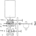
- FIG. 1 shows a jaw-connected gear 1 with two independently movable positive-locking elements A, B, which are designed here as sliding sleeves.
- the two sliding sleeves A, B are rotatably but slidably mounted on a drive shaft 2.
- the Drive shaft 2 is driven by a drive motor 3, in which it is z. B. may be an electric motor.
- a first gear 4 and a second gear 5 are rotatably arranged.
- a countershaft / output shaft 6 is arranged.
- a third gear 7 is rotatably disposed, which meshes with the first gear 4.
- a fourth gear 8 is rotatably disposed on the countershaft / output shaft 6, which meshes with the second gear 5.
- the first positive locking element formed by the sliding sleeve A rotatably and slidably disposed on the drive shaft 2.
- first shift position (open position) of the sliding sleeve A this is decoupled from the first gear 4.
- the first gear 4 can thus rotate independently of the sliding sleeve A and the thus rotatably coupled drive shaft 2.
- a freewheel 9 is arranged, which can be brought by moving the sliding sleeve A to the right into engagement with a form-locking element 10 of the first gear 4, which will be explained later in more detail.
- the second form-locking element B formed by the second sliding sleeve B is arranged rotatably and displaceably on the drive shaft 2.
- the clutch K has a first coupling element 11 (outer disk carrier), which is non-rotatably connected to the second gear 5, and a second Coupling element 12 (inner disk carrier), which can be rotationally coupled by moving the second sliding sleeve B with this.
- an output gear 13 is arranged, which meshes with a drive wheel 14 of a differential gear 15, which has a left output shaft 16 and a right output shaft 17.
- FIG. 2 shows the operating state in which the first gear is engaged.
- the sliding sleeve A is in a shift position shifted to the right, in which the freewheel 9 is in engagement with the first gear 4.
- the second shift sleeve B is also shifted to the right in a shift position, which is referred to as "first shift position".
- first shift position In the first switching position of the sliding sleeve B is a positive connection element 18 of the second sliding sleeve B in engagement with the first gear 4.
- the positive locking element 18 of the second sliding sleeve B passes through the first sliding sleeve A.
- the first gear in both directions with the second sliding sleeve B and thus rotatably coupled to the drive shaft 2, ie both in overrun mode and in train operation.
- FIG. 3 shows an operating state in which a gear change from the first to the second gear is prepared.
- the clutch K is opened, unless it was already open anyway.
- the sliding sleeve B is moved to the left, in a position in which the Positive locking element 18 of the sliding sleeve B disengaged, that is no longer in engagement with the first gear 4 is.
- FIG. 4 shows the phase of the engagement of the second gear, ie the phase of the torque transfer from the first gear to the second gear. This is done by closing the clutch K. As indicated by the dashed line, the torque flow takes place with second gear engaged, ie with the clutch K, from the drive shaft 2 via the sliding sleeve B to the second coupling element 12 and from this via the first coupling element 13 on the second gear 5 and from this to the fourth gear. 8
- FIG. 4 it can be seen, in this phase, the sliding sleeve A is still in its right switching position (second switching position), in which the freewheel 9 is still in engagement with the first gear 4. Since in the second gear at the same drive motor speed, the countershaft / output shaft 6 rotates faster than in the first gear, and the first gear 4 rotates correspondingly faster than the drive shaft 2. This is made possible by the freewheel 9. The freewheel 9 thus allows the first gear 4 to "overtake" the drive shaft 2 with respect to its rotational speed.
- FIG. 5 shows the completion of the gear change from first gear to second gear.
- the sliding sleeve A in their already in FIG. 1 shown shifted first position to the left, in which the freewheel 9 is decoupled from the first gear 4.
- FIG. 6 shows the preparation of a downshift, ie a shift from second gear to first gear.
- the sliding sleeve A is first moved to the right in its second switching position.
- the freewheel 9 is brought into engagement with the first gear 4. Since the first gear 4 is driven by the third gear 7, the first gear 4 rotates faster than the drive shaft 2.
- the freewheel 9 is thus in the freewheeling state, which allows the already mentioned above overtaking the drive shaft 2 by the first gear 4.
- FIG. 7 shows the next phase of the downshift.
- the clutch K is opened, which causes the freewheel is "overtaken", ie that the freewheel takes over the torque transmission.
- the sliding sleeve B moved to the right.
- the second coupling element 12 is decoupled from the sliding sleeve B and the interlocking element 18 of the sliding sleeve B is locked to the first gear 4.
- the actuation of the sliding sleeves A, B can, for. B. done electromechanically by servo motors.
- a hydraulic actuation of the sliding sleeves by means of a system with a hydraulic pressure accumulator would be conceivable.
- a hydraulic system with a pressure accumulator would be significantly more efficient.
- the loss of friction during normal operation in first gear or in second gear can be minimized. This is achieved by using the lossy elements "clutch” and “freewheel” only during the shifts and the number of gearing interventions is minimal.
- these can be switched by means of simple directional control valves. A fine adjustment is not required. Even with a failure of the Kupplungsaktutechnik circuits are still possible with traction interruption. Thus, a high system availability is guaranteed.
Landscapes
- Engineering & Computer Science (AREA)
- General Engineering & Computer Science (AREA)
- Mechanical Engineering (AREA)
- Structure Of Transmissions (AREA)
- Arrangement And Mounting Of Devices That Control Transmission Of Motive Force (AREA)
Description
- Die vorliegende Erfindung betrifft ein Lastschaltgetriebe gemäß dem Oberbegriff des Patentanspruches 1.
- Aus der gattungsgemäßen
WO 2008/096140 A1 ist eine Antriebseinrichtung bekannt. Aus derDE 218 543 C ist ein Zahnräder-Wechsel- und Wendegetriebe bekannt. - Bei Pkw-Fahrzeugen mit reinem Elektroantrieb werden bislang überwiegend Elektroantriebe mit festem Übersetzungsverhältnis eingesetzt. Auch ein Elektromotor ist aber nicht über sein gesamtes Drehmoment-/Drehzahlkennfeld gleichermaßen effizient. Um die Effizienz weiter zu optimieren, wäre eine zweite Gangstufe von Vorteil.
- Ein Zweiganggetriebe könnte z.B. als Planetengetriebe mit zwei Kupplungen bzw. Bremsen dargestellt werden. Jeder der beiden Gänge hätte dann seine eigene Kupplung. Um einen Gang einzulegen müsste eine der beiden Kupplungen z. B. hydraulisch geschlossen werden. Der Schaltvorgang könnte dann zugkraftunterbrechungsfrei und komfortabel ausgeführt werden. Aufgrund der im Ölbad offen mitlaufenden zweiten Kupplung bzw. Bremse entstünden aber nicht zu vernachlässigende Schlupfverluste.
- Ein Zweiganggetriebe könnte auch als Doppelkupplungsgetriebe dargestellt werden. Jeder der beiden Gänge hätte seine eigene Kupplung, die hydraulisch oder elektromechanisch angesteuert würde. Auch hier träten an der offenen Kupplung beträchtliche Schlupfverluste auf.
- Eine weitere Möglichkeit bestünde in einer synchronisierten Klauenschaltung. Um einen komfortablen Gangwechsel zu ermöglichen, müsste der Elektromotor in der Drehzahl vor dem Einlegen eines Ganges "angeglichen" werden. Der Schaltvorgang könnte aber nicht zugkraftunterbrechungsfrei ausgeführt werden. Lastschaltungen wären somit nicht möglich.
- Aufgabe der Erfindung ist es, ein Lastschaltgetriebe, insbesondere für Elektrofahrzeuge, anzugeben, das konstruktiv einfach aufgebaut ist und das einen hohen Wirkungsgrad aufweist.
- Diese Aufgabe wird durch die Merkmale des Patentanspruches 1 gelöst. Vorteilhafte Ausgestaltungen und Weiterbildungen der Erfindung sind den Unteransprüchen zu entnehmen.
- Ausgangspunkt der Erfindung ist ein Getriebe, insbesondere ein Lastschaltgetriebe, mit einer Antriebswelle, auf der ein erstes Zahnrad und ein zweites Zahnrad jeweils drehbar angeordnet ist.
- Parallel zur Antriebswelle ist eine Vorgelege-/Abtriebswelle angeordnet, über die Drehmoment z. B. auf ein Differentialgetriebe übertragen werden kann. Auf der Vorgelege-/Abtriebswelle ist ein drittes Zahnrad drehfest angeordnet, welches permanent mit dem auf der Antriebswelle angeordneten ersten Zahnrad kämmt. Ferner ist auf der Vorgelege-/Abtriebswelle ein viertes Zahnrad drehfest angeordnet, das permanent mit dem auf der Antriebswelle drehbar angeordneten zweiten Zahnrad kämmt.
- Desweiteren ist ein erstes "Formschlusselement" drehfest und verschieblich auf der Vorgelege-/Abtriebswelle angeordnet. Das Formschlusselement kann eine erste Schaltposition einnehmen, in der es von dem ersten Zahnrad "entkoppelt" ist. In der ersten Schaltposition kann sich somit das erste Zahnrad in beide möglichen Drehrichtungen relativ zu dem ersten Formschlusselement und der Antriebswelle drehen. In einer zweiten Schaltposition ist das Formschlusselement zumindest in einer Drehrichtung mit dem ersten Zahnrad drehgekoppelt.
- Ein wesentlicher Gedanke der Erfindung besteht darin, dass das erste Formschlusselement in seiner zweiten Schaltposition in einer ersten Drehrichtung des Zahnrads mit dem ersten Zahnrad drehgekoppelt ist und in einer der ersten Drehrichtung entgegengesetzten zweiten Drehrichtung des ersten Zahnrads über einen Freilauf von dem ersten Zahnrad entkoppelt ist. Das erste Zahnrad kann sich somit in der zweiten Drehrichtung auch bei geschlossenem Formschlusselement relativ zu diesem bzw. relativ zu der drehfest mit dem ersten Formschlusselement verbundenen Antriebswelle drehen.
- Es kann vorgesehen sein, dass der Freilauf an dem ersten Formschlusselement angeordnet und zusammen mit diesem relativ zur Antriebswelle verschiebbar ist. In der zweiten Schaltposition steht der Freilauf in Eingriff mit dem ersten Zahnrad, was eine Drehmomentübertragung in der ersten Drehrichtung ermöglicht. In der zweiten Drehrichtung hingegen kann sich das Zahnrad relativ zu dem ersten Formschlusselement bzw. zu der Antriebswelle drehen.
- Nach einer Weiterbildung der Erfindung ist ein zweites Formschlusselement vorgesehen, das drehfest und verschieblich auf der Vorgelege-/Abtriebswelle angeordnet ist.
- Ferner kann eine Kupplung vorgesehen sein, die z. B. als Lamellenkupplung ausgebildet sein kann und die ein erstes Kupplungselement aufweist, das drehfest mit dem zweiten Zahnrad verbunden ist, und ein zweites Kupplungselement.
- Das zweite Formschlusselement kann eine erste Schaltposition einnehmen, in der es drehfest mit dem ersten Zahnrad gekoppelt ist. Befindet sich das zweite Formschlusselement in seiner ersten Schaltposition, so ist das erste Zahnrad in beide Drehrichtungen drehfest mit der Antriebswelle gekoppelt.
- Erfindungsgemäß ist vorgesehen, dass das zweite Formschlusselement in der ersten Schaltposition das erste Formschlusselement durchgreift oder übergreift. Befindet sich das zweite Formschlusselement in Eingriff mit dem ersten Zahnrad, so sperrt es den am ersten Formschlusselement vorgesehenen Freilauf, d. h. das erste Zahnrad ist dann permanent und in beide Drehrichtungen drehfest mit der Antriebswelle gekoppelt.
- Das zweite Formschlusselement kann ferner eine zweite Schaltposition einnehmen, in der es von dem ersten Zahnrad entkoppelt und drehfest mit dem zweiten Kupplungselement gekoppelt ist.
- Im Folgenden wird die Erfindung im Zusammenhang mit der Zeichnung näher erläutert. Es zeigen:
-
Figur 1 den konstruktiven Aufbau eines Zwei-Gang-Lastschaltgetriebes gemäß der Erfindung; -
Figur 2 - 10 verschiedene Betriebszustände des inFigur 1 gezeigten Getriebes. -
Figur 1 zeigt ein klauengeschaltetes Getriebe 1 mit zwei unabhängig voneinander verschiebbaren Formschlusselementen A, B, die hier als Schiebemuffen ausgebildet sind. Die beiden Schiebemuffen A, B sind drehfest aber verschieblich auf einer Antriebswelle 2 angeordnet. Die Antriebswelle 2 wird von einem Antriebsmotor 3 angetrieben, bei dem es sich z. B. um einen Elektromotor handeln kann. - Auf der Antriebswelle 2 sind drehbar ein erstes Zahnrad 4 und eine zweites Zahnrad 5 angeordnet.
- Parallel zur Antriebswelle 2 ist eine Vorgelege-/Abtriebswelle 6 angeordnet. Auf der Vorgelege-/Abtriebswelle 8 ist drehfest ein drittes Zahnrad 7 angeordnet, das mit dem ersten Zahnrad 4 kämmt. Ferner ist auf der Vorgelege-/Abtriebswelle 6 ein viertes Zahnrad 8 drehfest angeordnet, das mit dem zweiten Zahnrad 5 kämmt.
- Das durch die Schiebemuffe A gebildete erste Formschlusselement ist, wie bereits erwähnt, drehfest und verschieblich auf der Antriebswelle 2 angeordnet. In der in
Figur 1 gezeigten ersten Schaltposition (Öffnungsstellung) der Schiebemuffe A ist diese entkoppelt von dem ersten Zahnrad 4. Das erste Zahnrad 4 kann sich also unabhängig von der Schiebemuffe A bzw. der damit drehgekoppelten Antriebswelle 2 drehen. - An der Schiebemuffe A ist ein Freilauf 9 angeordnet, der durch Verschieben der Schiebemuffe A nach rechts in Eingriff mit einem Formschlusselement 10 des ersten Zahnrads 4 gebracht werden kann, was später noch näher erläutert wird.
- Links neben der Schiebemuffe A ist das durch die zweite Schiebemuffe B gebildete zweite Formschlusselement B drehfest und verschieblich auf der Antriebswelle 2 angeordnet.
- Ebenfalls auf der Antriebswelle 2 bzw. koaxial dazu ist eine Kupplung K angeordnet, die hier durch eine Lamellenkupplung gebildet ist. Die Kupplung K weist ein erstes Kupplungselement 11 (Außenlamellenträger) auf, das drehfest mit dem zweiten Zahnrad 5 verbunden ist, sowie ein zweites Kupplungselement 12 (Innenlamellenträger), das durch Verschieben der zweiten Schiebemuffe B mit dieser drehgekoppelt werden kann.
- Auf der Vorgelege-/Abtriebswelle 6 ist ein Abtriebszahnrad 13 angeordnet, welches mit einem Antriebsrad 14 eines Differentialgetriebes 15 kämmt, das eine linke Abtriebswelle 16 und ein reche Abtriebswelle 17 aufweist.
-
Figur 2 zeigt den Betriebszustand, bei dem der erste Gang eingelegt ist. In diesem Betriebszustand befindet sich die Schiebemuffe A in einer nach rechts verschobenen Schaltposition, in der der Freilauf 9 in Eingriff mit dem ersten Zahnrad 4 steht. - Die zweite Schiebemuffe B ist ebenfalls nach rechts in eine Schaltposition verschoben, die als "erste Schaltposition" bezeichnet wird. In der ersten Schaltposition der Schiebemuffe B befindet sich ein Formschlusselement 18 der zweiten Schiebemuffe B in Eingriff mit dem ersten Zahnrad 4. Wie aus
Figur 2 ersichtlich ist, durchgreift das Formschlusselement 18 der zweiten Schiebemuffe B die erste Schiebemuffe A. Über das Formschlusselement 18 ist das erste Zahnrad in beide Drehrichtungen mit der zweiten Schiebemuffe B und somit mit der Antriebswelle 2 drehgekoppelt, d. h. sowohl im Schubbetrieb als auch im Zugbetrieb. - Der Drehmomentfluss in diesem Betriebszustand ist gestrichelt eingezeichnet. Im Zugbetrieb wird Drehmoment von der Antriebswelle 2 über die Schiebemuffe A, den Freilauf 9, das erste Zahnrad 4, das dritte Zahnrad 7, das Abtriebsrad 13, und das Antriebsrad 14 auf das Differentialgetriebe 15 übertragen.
-
Figur 3 zeigt einen Betriebszustand, in dem ein Gangwechsel vom ersten auf den zweiten Gang vorbereitet wird. Hierzu wird zunächst die Kupplung K geöffnet, sofern sie nicht ohnehin bereits offen war. Anschließend wird die Schiebemuffe B nach links verschoben, in eine Stellung, in der das Formschlusselement 18 der Schiebemuffe B außer Eingriff, d. h. nicht mehr im Eingriff mit dem ersten Zahnrad 4 steht. - Durch das nach links Verschieben der Schiebemuffe B wird diese in Eingriff mit dem zweiten Kupplungselement 12 (Innenlamellenträger) gebracht. Der zweite Gang überträgt zunächst noch kein Drehmoment, da die Kupplung K geöffnet ist. Drehmoment wird vielmehr weiterhin von der Antriebswelle 2 auf die Schiebmuffe A und von dieser über den Freilauf 9 auf das erste Zahnrad 4 übertragen.
-
Figur 4 zeigt die Phase des Einlegens des zweiten Gangs, d. h. die Phase der Momentenübergabe vom ersten Gang auf den zweiten Gang. Dies geschieht durch Schließen der Kupplung K. Wie durch die gestrichelte Linie angedeutet ist, erfolgt der Drehmomentfluss bei eingelegtem zweiten Gang, d. h. bei geschlossener Kupplung K, von der Antriebswelle 2 über die Schiebemuffe B auf das zweite Kupplungselement 12 und von diesem über das erste Kupplungselement 13 auf das zweite Zahnrad 5 und von diesem auf das vierte Zahnrad 8. - Wie aus
Figur 4 ersichtlich ist, befindet sich in dieser Phase die Schiebemuffe A noch in ihrer rechten Schaltposition (zweite Schaltposition), in der der Freilauf 9 weiterhin in Eingriff mit dem ersten Zahnrad 4 steht. Da sich im zweiten Gang bei gleicher Antriebsmotordrehzahl die Vorgelegewelle-/Abtriebswelle 6 schneller dreht als im ersten Gang, dreht sich auch das erste Zahnrad 4 entsprechend schneller als die Antriebswelle 2. Dies wird durch den Freilauf 9 ermöglicht. Der Freilauf 9 gestattet es also, dass das erste Zahnrad 4 hinsichtlich seiner Drehzahl die Antriebswelle 2 "überholt". -
Figur 5 zeigt den Abschluss des Gangwechsels vom ersten Gang in den zweiten Gang. Hierzu wird die Schiebemuffe A in ihre bereits inFigur 1 gezeigte erste Position nach links verschoben, in der der Freilauf 9 vom ersten Zahnrad 4 entkoppelt ist. - Wie anhand der einzelnen Figuren nachvollziehbar ist, erfolgt das Schalten vom ersten in den zweiten Gang ohne jeglichen Drehmomenteinbruch.
-
Figur 6 zeigt die Vorbereitung einer Rückschaltung, d. h. einer Schaltung vom zweiten Gang in den ersten Gang. Hierzu wird zunächst die Schiebemuffe A nach rechts in ihre zweite Schaltposition verschoben. Dadurch wird der Freilauf 9 in Eingriff mit dem ersten Zahnrad 4 gebracht. Da das erste Zahnrad 4 durch das dritte Zahnrad 7 angetrieben wird, dreht das erste Zahnrad 4 schneller als die Antriebswelle 2. Der Freilauf 9 befindet sich also im Freilaufzustand, was das oben bereits erwähnte Überholen der Antriebswelle 2 durch das erste Zahnrad 4 ermöglicht. -
Figur 7 zeigt die nächste Phase des Rückschaltvorgangs. Hierbei wird die Kupplung K geöffnet, was dazu führt, dass der Freilauf "eingeholt" wird, d. h. dass der Freilauf die Drehmomentübertragung übernimmt. Anschließend wird, wie inFigur 8 dargestellt, bei geöffneter Kupplung K die Schiebemuffe B nach rechts verschoben. Dadurch wird das zweite Kupplungselement 12 von der Schiebemuffe B entkoppelt und das Formschlusselement 18 der Schiebemuffe B mit dem ersten Zahnrad 4 verriegelt. - Dadurch wird in
Figur 9 wieder der inFigur 2 gezeigte Schaltzustand erreicht, wobei die gestrichelte Linie inFigur 9 den Drehmomentfluss im Zugbetrieb zeigt. - Die Aktuierung der Schiebemuffen A, B kann z. B. elektromechanisch mittels Servomotoren erfolgen. Alternativ dazu wäre auch eine hydraulische Aktuierung der Schiebemuffen mittels eines Systems mit einem hydraulischen Druckspeicher denkbar. Im Vergleich zu permanent fördernden Hydrauliksystemen, wie sie z. b. von Automatik- oder Doppelkupplungsgetrieben bekannt sind, wäre ein hydraulisches System mit einem Druckspeicher deutlich effizienter.
- Mit dem erfindungsgemäßen Getriebe kann die Verlustreibung während des normalen Betriebs im ersten Gang oder im zweiten Gang minimiert werden. Dies wird dadurch erreicht, dass die verlustbehafteten Elemente "Kupplung" und "Freilauf" nur während der Schaltvorgänge verwendet werden und die Anzahl der Verzahnungseingriffe minimal ist. Für den Fall einer hydraulischen Aktuierung der Schiebemuffen A, B können diese mittels einfacher Wegeventile umgeschaltet werden. Eine Feinregulierung ist nicht erforderlich. Selbst bei einem Ausfall der Kupplungsaktuierung sind immer noch Schaltungen mit Zugkraftunterbrechung möglich. Somit ist eine hohe Systemverfügbarkeit gewährleistet.
Claims (6)
- Lastschaltgetriebe (1), mit- einer Antriebswelle (2),- einem ersten Zahnrad (4) und einem zweiten Zahnrad (5), die jeweils drehbar auf der Antriebswelle (2) angeordnet sind,- einer Vorgelege-/Abtriebswelle (6),- einem dritten Zahnrad (7), das drehfest auf der Vorgelege-/Abtriebswelle (6) angeordnet ist und das mit dem ersten Zahnrad (4) kämmt,- einem vierten Zahnrad (8), das drehfest auf der Vorgelege-/Abtriebswelle (6) angeordnet ist und das mit dem zweiten Zahnrad (5) kämmt,- einem ersten Formschlusselement (A), das drehfest und verschieblich auf der Antriebswelle (2) angeordnet ist- und das in einer ersten Schaltposition entkoppelt von dem ersten Zahnrad (4) ist- und das in einer zweiten Schaltposition mit dem ersten Zahnrad (4) drehgekoppelt istwobei das erste Formschlusselement (A) in der zweiten Schaltposition- in einer ersten Drehrichtung des ersten Zahnrads (4) mit dem ersten Zahnrad (4) drehgekoppelt ist und- in einer der ersten Drehrichtung entgegengesetzten zweiten Drehrichtung des ersten Zahnrads (4) über einen Freilauf (9) von dem ersten Zahnrad (4) entkoppelt ist und wobeiein zweites Formschlusselement (B) vorgesehen ist, das drehfest und verschieblich auf der Antriebswelle angeordnet ist und wobei das zweite Formschlusselement (B) eine erste Schaltposition einnehmen kann, in der es drehfest mit dem ersten Zahnrad (4) gekoppelt ist
dadurch gekennzeichnet, dass
das zweite Formschlusselement (B) in der ersten Schaltposition das erste Formschlusselement (A) durchgreift oder übergreift. - Lastschaltgetriebe nach Anspruch 1, dadurch gekennzeichnet, dass der Freilauf (9) an dem ersten Formschlusselement (A) angeordnet und in der zweiten Schaltposition in Eingriff mit dem ersten Zahnrad (4) ist.
- Lastschaltgetriebe nach einem der Ansprüche 1, dadurch gekennzeichnet, dass eine Kupplung (K) vorgesehen ist, die ein erstes Kupplungselement (11) aufweist, das drehfest mit dem zweiten Zahnrad (5) verbunden ist, und ein zweites Kupplungselement (12).
- Lastschaltgetriebe nach einem der Ansprüche 1 bis 3, dadurch gekennzeichnet, dass das zweite Formschlusselement (B) eine zweite Schaltposition einnehmen kann, in der es von dem ersten Zahnrad (4) entkoppelt ist und drehfest mit dem zweiten Kupplungselement (12) gekoppelt ist.
- Lastschaltgetriebe nach einem der Ansprüche 1 bis 4, dadurch gekennzeichnet, dass ein Elektromotor (3) zum Antreiben der Antriebswelle (2) vorgesehen ist.
- Lastschaltgetriebe nach einem der Ansprüche 1 bis 5, dadurch gekennzeichnet, dass auf der Vorgelege-/Abtriebswelle (6) ein fünftes Rad (13) angeordnet ist, das mit einem Antriebsrad (14) eines Differentialgetriebes (15) kämmt.
Applications Claiming Priority (2)
| Application Number | Priority Date | Filing Date | Title |
|---|---|---|---|
| DE102013207413.1A DE102013207413B4 (de) | 2013-04-24 | 2013-04-24 | Lastschaltgetriebe, insbesondere für Elektroantriebe |
| PCT/EP2014/056764 WO2014173651A1 (de) | 2013-04-24 | 2014-04-04 | Lastschaltgetriebe, insbesondere für elektroantriebe |
Publications (2)
| Publication Number | Publication Date |
|---|---|
| EP2989348A1 EP2989348A1 (de) | 2016-03-02 |
| EP2989348B1 true EP2989348B1 (de) | 2019-11-06 |
Family
ID=50434202
Family Applications (1)
| Application Number | Title | Priority Date | Filing Date |
|---|---|---|---|
| EP14715014.8A Active EP2989348B1 (de) | 2013-04-24 | 2014-04-04 | Lastschaltgetriebe, insbesondere für elektroantriebe |
Country Status (3)
| Country | Link |
|---|---|
| EP (1) | EP2989348B1 (de) |
| DE (1) | DE102013207413B4 (de) |
| WO (1) | WO2014173651A1 (de) |
Families Citing this family (10)
| Publication number | Priority date | Publication date | Assignee | Title |
|---|---|---|---|---|
| DE102015110839A1 (de) * | 2015-07-06 | 2017-01-12 | Dr. Ing. H.C. F. Porsche Aktiengesellschaft | Elektrischer Achsantrieb für ein Kraftfahrzeug |
| CN105041988A (zh) * | 2015-08-25 | 2015-11-11 | 重庆青山工业有限责任公司 | 一种两档纯电动汽车变速器 |
| DE102016205491A1 (de) * | 2016-04-04 | 2017-10-05 | Zf Friedrichshafen Ag | Getriebeanordnung zum Antrieb eines Kraftfahrzeugs |
| CN105864368B (zh) * | 2016-06-24 | 2018-02-13 | 包凯 | 一种电动车无动力中断换挡变速箱及其换挡控制方法 |
| CN106114202A (zh) * | 2016-07-26 | 2016-11-16 | 连云港北方变速器有限责任公司 | 电动汽车两档amt后桥总成 |
| CN108131426A (zh) * | 2017-11-17 | 2018-06-08 | 南京航空航天大学 | 一种摩擦片离合器式两级自动换挡变扭齿轮机构 |
| DE102018129269A1 (de) | 2017-12-06 | 2019-06-27 | Schaeffler Technologies AG & Co. KG | Geteilte Schiebemuffe |
| DE102019202015A1 (de) * | 2019-02-14 | 2020-08-20 | Robert Bosch Gmbh | Lastschaltbares Mehr-Gang-Getriebe mit Freilauf |
| DE102019121735B3 (de) * | 2019-08-13 | 2020-12-17 | Iav Gmbh Ingenieurgesellschaft Auto Und Verkehr | Fahrzeugantrieb mit einer elektrischen Maschine und Untersetzungsgetriebe |
| CN113771608B (zh) * | 2021-09-26 | 2023-04-14 | 东莞市零越传动科技有限公司 | 用于电动车辆的驱动系统 |
Citations (2)
| Publication number | Priority date | Publication date | Assignee | Title |
|---|---|---|---|---|
| DE967545C (de) * | 1953-10-13 | 1957-11-21 | Georg Heim | Zahnraederwechselgetriebe, insbesondere fuer Kraftfahrzeuge mit Verbrennungsmotoren |
| DE10149173A1 (de) * | 2001-10-04 | 2003-04-17 | Werenfrid Doepper | Verbindungsglied (Kupplungselement)zur torsionsmomentenunterbrechungsfreien Übersetzungsumschaltung in Getrieben |
Family Cites Families (11)
| Publication number | Priority date | Publication date | Assignee | Title |
|---|---|---|---|---|
| DE218543C (de) * | ||||
| GB363772A (en) * | 1930-10-30 | 1931-12-31 | Egon Neurath | Speed-changing mechanism for motor car gearings |
| DE969740C (de) * | 1953-11-10 | 1958-07-10 | Georg Heim | Zahnraederwechselgetriebe, insbesondere fuer Kraftfahrzeuge mit Verbrennungsmotoren |
| FR1420205A (fr) * | 1965-01-09 | 1965-12-03 | Enclenchement des rapports par roues libres sur boîte à vitesse mécanique | |
| JPH08226501A (ja) * | 1995-02-20 | 1996-09-03 | Toyota Motor Corp | 自動変速機 |
| DE19824415A1 (de) * | 1998-05-30 | 1999-12-02 | Volkswagen Ag | Doppelwellengetriebe und ein Verfahren zu dessen Betrieb |
| DE10037398A1 (de) * | 2000-08-01 | 2002-02-14 | Daimler Chrysler Ag | Zahnräderwechselgetriebe |
| FR2819570B1 (fr) * | 2001-01-16 | 2003-04-11 | Renault | Boite de vitesses a commande robotisee de vehicule automobile et procede de gestion d'une unite electronique de commande d'une telle boite |
| GB0702548D0 (en) * | 2007-02-09 | 2007-03-21 | Zeroshift Ltd | Gearbox |
| FR2946293B1 (fr) * | 2009-06-08 | 2013-01-25 | Renault Sas | Groupe motopropulseur pour vehicule electrique a trois arbres permettant d'obtenir deux rapports de transmission |
| DE102011112091A1 (de) * | 2011-09-02 | 2013-03-07 | Lsp Innovative Automotive Systems Gmbh | Elektrisches Antriebssystem für ein batteriegetriebenes Leichtfahrzeug |
-
2013
- 2013-04-24 DE DE102013207413.1A patent/DE102013207413B4/de active Active
-
2014
- 2014-04-04 EP EP14715014.8A patent/EP2989348B1/de active Active
- 2014-04-04 WO PCT/EP2014/056764 patent/WO2014173651A1/de active Application Filing
Patent Citations (2)
| Publication number | Priority date | Publication date | Assignee | Title |
|---|---|---|---|---|
| DE967545C (de) * | 1953-10-13 | 1957-11-21 | Georg Heim | Zahnraederwechselgetriebe, insbesondere fuer Kraftfahrzeuge mit Verbrennungsmotoren |
| DE10149173A1 (de) * | 2001-10-04 | 2003-04-17 | Werenfrid Doepper | Verbindungsglied (Kupplungselement)zur torsionsmomentenunterbrechungsfreien Übersetzungsumschaltung in Getrieben |
Also Published As
| Publication number | Publication date |
|---|---|
| DE102013207413B4 (de) | 2017-03-30 |
| EP2989348A1 (de) | 2016-03-02 |
| WO2014173651A1 (de) | 2014-10-30 |
| DE102013207413A1 (de) | 2014-10-30 |
Similar Documents
| Publication | Publication Date | Title |
|---|---|---|
| EP2989348B1 (de) | Lastschaltgetriebe, insbesondere für elektroantriebe | |
| EP1781968B1 (de) | Lastschaltgetriebe und schaltverfahren dafür | |
| DE2342771C2 (de) | Wechselgetriebe mit Bereichsumschaltung | |
| DE4400701C2 (de) | Übertragungsvorrichtung zur Übertragung einer Motorleistung auf Antriebsräder eines Fahrzeuges | |
| EP2652363B1 (de) | Verfahren zum betreiben einer getriebevorrichtung eines fahrzeugantriebsstranges | |
| WO2015014453A1 (de) | Schaltgetriebe für eine antriebseinheit eines elektrofahrzeugs und verfahren zum betrieb des schaltgetriebes | |
| EP1817515A1 (de) | Aktuatoranordnung mit schaltwalzen für ein doppelkupplungsgetriebe | |
| WO2018072780A1 (de) | Doppelkupplungsgetriebe | |
| DE102012206936A1 (de) | Hybridgetriebe | |
| DE102012209999B4 (de) | Doppelkupplungsgetriebe und Verfahren zum Schalten eines Doppelkupplungsgetriebes | |
| WO2008092566A1 (de) | Schaltgetriebe mit doppelter kupplung | |
| EP3679273A1 (de) | Achsantriebseinheit mit einem lastschaltbaren 2-gang getriebe | |
| DE112014000378T5 (de) | Getriebe für ein Fahrzeug und Fahrzeug mit einem derartigen Getriebe | |
| EP2828558A1 (de) | Kraftfahrzeugantriebsstrangvorrichtung mit einem mehrgruppengetriebe | |
| DE112014000456T5 (de) | Handschaltgetriebe | |
| AT512917B1 (de) | Verfahren zum Betreiben eines Doppelkupplungsgetriebes | |
| WO2013127510A1 (de) | Schaltvorrichtung für geschwindigkeits-wechselgetriebe | |
| EP1002971B1 (de) | Kraftfahrzeug-Antriebsstrang und Verfahren zum Steuern eines Schaltvorganges eines Kraftfahrzeug-Antriebsstranges | |
| DE19930972C1 (de) | Verfahren zum Lastschalten eines Antriebsstranges, lastschaltbarer Antriebsstrang und Kupplungseinrichtung für einen lastschaltbaren Antriebsstrang | |
| DE102014115371B4 (de) | Schaltanordnung für ein Kraftfahrzeuggetriebe und Schaltverfahren | |
| WO2003085287A2 (de) | Lastschaltgetriebe und verfahren zur steuerung eines doppelkupplungsgetriebes | |
| DE102010024768A1 (de) | Kraftfahrzeuggruppengetriebevorrichtung | |
| DE102018220895A1 (de) | Antriebsanordnung für ein Fahrzeug mit zwei gleichwertigen Fahrtrichtungen und Verfahren | |
| DE102021130319B4 (de) | Steuervorrichtung und Verfahren zum Einlegen eines Startganges in einem Getriebe | |
| DE102011105065A1 (de) | Zweiwellenschaltgetriebe für ein Kraftfahrzeug |
Legal Events
| Date | Code | Title | Description |
|---|---|---|---|
| PUAI | Public reference made under article 153(3) epc to a published international application that has entered the european phase |
Free format text: ORIGINAL CODE: 0009012 |
|
| 17P | Request for examination filed |
Effective date: 20150730 |
|
| AK | Designated contracting states |
Kind code of ref document: A1 Designated state(s): AL AT BE BG CH CY CZ DE DK EE ES FI FR GB GR HR HU IE IS IT LI LT LU LV MC MK MT NL NO PL PT RO RS SE SI SK SM TR |
|
| AX | Request for extension of the european patent |
Extension state: BA ME |
|
| DAX | Request for extension of the european patent (deleted) | ||
| STAA | Information on the status of an ep patent application or granted ep patent |
Free format text: STATUS: EXAMINATION IS IN PROGRESS |
|
| 17Q | First examination report despatched |
Effective date: 20181126 |
|
| GRAP | Despatch of communication of intention to grant a patent |
Free format text: ORIGINAL CODE: EPIDOSNIGR1 |
|
| STAA | Information on the status of an ep patent application or granted ep patent |
Free format text: STATUS: GRANT OF PATENT IS INTENDED |
|
| INTG | Intention to grant announced |
Effective date: 20190724 |
|
| GRAS | Grant fee paid |
Free format text: ORIGINAL CODE: EPIDOSNIGR3 |
|
| GRAA | (expected) grant |
Free format text: ORIGINAL CODE: 0009210 |
|
| STAA | Information on the status of an ep patent application or granted ep patent |
Free format text: STATUS: THE PATENT HAS BEEN GRANTED |
|
| AK | Designated contracting states |
Kind code of ref document: B1 Designated state(s): AL AT BE BG CH CY CZ DE DK EE ES FI FR GB GR HR HU IE IS IT LI LT LU LV MC MK MT NL NO PL PT RO RS SE SI SK SM TR |
|
| REG | Reference to a national code |
Ref country code: GB Ref legal event code: FG4D Free format text: NOT ENGLISH |
|
| REG | Reference to a national code |
Ref country code: CH Ref legal event code: EP Ref country code: AT Ref legal event code: REF Ref document number: 1199144 Country of ref document: AT Kind code of ref document: T Effective date: 20191115 |
|
| REG | Reference to a national code |
Ref country code: IE Ref legal event code: FG4D Free format text: LANGUAGE OF EP DOCUMENT: GERMAN |
|
| REG | Reference to a national code |
Ref country code: DE Ref legal event code: R096 Ref document number: 502014013000 Country of ref document: DE |
|
| REG | Reference to a national code |
Ref country code: NL Ref legal event code: MP Effective date: 20191106 |
|
| REG | Reference to a national code |
Ref country code: LT Ref legal event code: MG4D |
|
| PG25 | Lapsed in a contracting state [announced via postgrant information from national office to epo] |
Ref country code: FI Free format text: LAPSE BECAUSE OF FAILURE TO SUBMIT A TRANSLATION OF THE DESCRIPTION OR TO PAY THE FEE WITHIN THE PRESCRIBED TIME-LIMIT Effective date: 20191106 Ref country code: BG Free format text: LAPSE BECAUSE OF FAILURE TO SUBMIT A TRANSLATION OF THE DESCRIPTION OR TO PAY THE FEE WITHIN THE PRESCRIBED TIME-LIMIT Effective date: 20200206 Ref country code: NO Free format text: LAPSE BECAUSE OF FAILURE TO SUBMIT A TRANSLATION OF THE DESCRIPTION OR TO PAY THE FEE WITHIN THE PRESCRIBED TIME-LIMIT Effective date: 20200206 Ref country code: GR Free format text: LAPSE BECAUSE OF FAILURE TO SUBMIT A TRANSLATION OF THE DESCRIPTION OR TO PAY THE FEE WITHIN THE PRESCRIBED TIME-LIMIT Effective date: 20200207 Ref country code: LT Free format text: LAPSE BECAUSE OF FAILURE TO SUBMIT A TRANSLATION OF THE DESCRIPTION OR TO PAY THE FEE WITHIN THE PRESCRIBED TIME-LIMIT Effective date: 20191106 Ref country code: NL Free format text: LAPSE BECAUSE OF FAILURE TO SUBMIT A TRANSLATION OF THE DESCRIPTION OR TO PAY THE FEE WITHIN THE PRESCRIBED TIME-LIMIT Effective date: 20191106 Ref country code: PL Free format text: LAPSE BECAUSE OF FAILURE TO SUBMIT A TRANSLATION OF THE DESCRIPTION OR TO PAY THE FEE WITHIN THE PRESCRIBED TIME-LIMIT Effective date: 20191106 Ref country code: PT Free format text: LAPSE BECAUSE OF FAILURE TO SUBMIT A TRANSLATION OF THE DESCRIPTION OR TO PAY THE FEE WITHIN THE PRESCRIBED TIME-LIMIT Effective date: 20200306 Ref country code: LV Free format text: LAPSE BECAUSE OF FAILURE TO SUBMIT A TRANSLATION OF THE DESCRIPTION OR TO PAY THE FEE WITHIN THE PRESCRIBED TIME-LIMIT Effective date: 20191106 Ref country code: SE Free format text: LAPSE BECAUSE OF FAILURE TO SUBMIT A TRANSLATION OF THE DESCRIPTION OR TO PAY THE FEE WITHIN THE PRESCRIBED TIME-LIMIT Effective date: 20191106 |
|
| PG25 | Lapsed in a contracting state [announced via postgrant information from national office to epo] |
Ref country code: IS Free format text: LAPSE BECAUSE OF FAILURE TO SUBMIT A TRANSLATION OF THE DESCRIPTION OR TO PAY THE FEE WITHIN THE PRESCRIBED TIME-LIMIT Effective date: 20200306 Ref country code: RS Free format text: LAPSE BECAUSE OF FAILURE TO SUBMIT A TRANSLATION OF THE DESCRIPTION OR TO PAY THE FEE WITHIN THE PRESCRIBED TIME-LIMIT Effective date: 20191106 Ref country code: HR Free format text: LAPSE BECAUSE OF FAILURE TO SUBMIT A TRANSLATION OF THE DESCRIPTION OR TO PAY THE FEE WITHIN THE PRESCRIBED TIME-LIMIT Effective date: 20191106 |
|
| PG25 | Lapsed in a contracting state [announced via postgrant information from national office to epo] |
Ref country code: AL Free format text: LAPSE BECAUSE OF FAILURE TO SUBMIT A TRANSLATION OF THE DESCRIPTION OR TO PAY THE FEE WITHIN THE PRESCRIBED TIME-LIMIT Effective date: 20191106 |
|
| PG25 | Lapsed in a contracting state [announced via postgrant information from national office to epo] |
Ref country code: ES Free format text: LAPSE BECAUSE OF FAILURE TO SUBMIT A TRANSLATION OF THE DESCRIPTION OR TO PAY THE FEE WITHIN THE PRESCRIBED TIME-LIMIT Effective date: 20191106 Ref country code: DK Free format text: LAPSE BECAUSE OF FAILURE TO SUBMIT A TRANSLATION OF THE DESCRIPTION OR TO PAY THE FEE WITHIN THE PRESCRIBED TIME-LIMIT Effective date: 20191106 Ref country code: RO Free format text: LAPSE BECAUSE OF FAILURE TO SUBMIT A TRANSLATION OF THE DESCRIPTION OR TO PAY THE FEE WITHIN THE PRESCRIBED TIME-LIMIT Effective date: 20191106 Ref country code: CZ Free format text: LAPSE BECAUSE OF FAILURE TO SUBMIT A TRANSLATION OF THE DESCRIPTION OR TO PAY THE FEE WITHIN THE PRESCRIBED TIME-LIMIT Effective date: 20191106 Ref country code: EE Free format text: LAPSE BECAUSE OF FAILURE TO SUBMIT A TRANSLATION OF THE DESCRIPTION OR TO PAY THE FEE WITHIN THE PRESCRIBED TIME-LIMIT Effective date: 20191106 |
|
| REG | Reference to a national code |
Ref country code: DE Ref legal event code: R097 Ref document number: 502014013000 Country of ref document: DE |
|
| PG25 | Lapsed in a contracting state [announced via postgrant information from national office to epo] |
Ref country code: SK Free format text: LAPSE BECAUSE OF FAILURE TO SUBMIT A TRANSLATION OF THE DESCRIPTION OR TO PAY THE FEE WITHIN THE PRESCRIBED TIME-LIMIT Effective date: 20191106 Ref country code: SM Free format text: LAPSE BECAUSE OF FAILURE TO SUBMIT A TRANSLATION OF THE DESCRIPTION OR TO PAY THE FEE WITHIN THE PRESCRIBED TIME-LIMIT Effective date: 20191106 |
|
| PLBE | No opposition filed within time limit |
Free format text: ORIGINAL CODE: 0009261 |
|
| STAA | Information on the status of an ep patent application or granted ep patent |
Free format text: STATUS: NO OPPOSITION FILED WITHIN TIME LIMIT |
|
| 26N | No opposition filed |
Effective date: 20200807 |
|
| PG25 | Lapsed in a contracting state [announced via postgrant information from national office to epo] |
Ref country code: SI Free format text: LAPSE BECAUSE OF FAILURE TO SUBMIT A TRANSLATION OF THE DESCRIPTION OR TO PAY THE FEE WITHIN THE PRESCRIBED TIME-LIMIT Effective date: 20191106 Ref country code: MC Free format text: LAPSE BECAUSE OF FAILURE TO SUBMIT A TRANSLATION OF THE DESCRIPTION OR TO PAY THE FEE WITHIN THE PRESCRIBED TIME-LIMIT Effective date: 20191106 |
|
| REG | Reference to a national code |
Ref country code: CH Ref legal event code: PL |
|
| PG25 | Lapsed in a contracting state [announced via postgrant information from national office to epo] |
Ref country code: LU Free format text: LAPSE BECAUSE OF NON-PAYMENT OF DUE FEES Effective date: 20200404 Ref country code: CH Free format text: LAPSE BECAUSE OF NON-PAYMENT OF DUE FEES Effective date: 20200430 Ref country code: LI Free format text: LAPSE BECAUSE OF NON-PAYMENT OF DUE FEES Effective date: 20200430 |
|
| REG | Reference to a national code |
Ref country code: BE Ref legal event code: MM Effective date: 20200430 |
|
| PG25 | Lapsed in a contracting state [announced via postgrant information from national office to epo] |
Ref country code: BE Free format text: LAPSE BECAUSE OF NON-PAYMENT OF DUE FEES Effective date: 20200430 |
|
| PG25 | Lapsed in a contracting state [announced via postgrant information from national office to epo] |
Ref country code: IE Free format text: LAPSE BECAUSE OF NON-PAYMENT OF DUE FEES Effective date: 20200404 |
|
| REG | Reference to a national code |
Ref country code: AT Ref legal event code: MM01 Ref document number: 1199144 Country of ref document: AT Kind code of ref document: T Effective date: 20200404 |
|
| PG25 | Lapsed in a contracting state [announced via postgrant information from national office to epo] |
Ref country code: AT Free format text: LAPSE BECAUSE OF NON-PAYMENT OF DUE FEES Effective date: 20200404 |
|
| PG25 | Lapsed in a contracting state [announced via postgrant information from national office to epo] |
Ref country code: TR Free format text: LAPSE BECAUSE OF FAILURE TO SUBMIT A TRANSLATION OF THE DESCRIPTION OR TO PAY THE FEE WITHIN THE PRESCRIBED TIME-LIMIT Effective date: 20191106 Ref country code: MT Free format text: LAPSE BECAUSE OF FAILURE TO SUBMIT A TRANSLATION OF THE DESCRIPTION OR TO PAY THE FEE WITHIN THE PRESCRIBED TIME-LIMIT Effective date: 20191106 Ref country code: CY Free format text: LAPSE BECAUSE OF FAILURE TO SUBMIT A TRANSLATION OF THE DESCRIPTION OR TO PAY THE FEE WITHIN THE PRESCRIBED TIME-LIMIT Effective date: 20191106 |
|
| PG25 | Lapsed in a contracting state [announced via postgrant information from national office to epo] |
Ref country code: MK Free format text: LAPSE BECAUSE OF FAILURE TO SUBMIT A TRANSLATION OF THE DESCRIPTION OR TO PAY THE FEE WITHIN THE PRESCRIBED TIME-LIMIT Effective date: 20191106 |
|
| P01 | Opt-out of the competence of the unified patent court (upc) registered |
Effective date: 20230502 |
|
| PGFP | Annual fee paid to national office [announced via postgrant information from national office to epo] |
Ref country code: GB Payment date: 20240423 Year of fee payment: 11 |
|
| PGFP | Annual fee paid to national office [announced via postgrant information from national office to epo] |
Ref country code: DE Payment date: 20240416 Year of fee payment: 11 |
|
| PGFP | Annual fee paid to national office [announced via postgrant information from national office to epo] |
Ref country code: IT Payment date: 20240430 Year of fee payment: 11 Ref country code: FR Payment date: 20240422 Year of fee payment: 11 |