EP2989348B1 - Boîte de vitesses couplable sous charge, destinée en particulier à des entraînements électriques - Google Patents
Boîte de vitesses couplable sous charge, destinée en particulier à des entraînements électriques Download PDFInfo
- Publication number
- EP2989348B1 EP2989348B1 EP14715014.8A EP14715014A EP2989348B1 EP 2989348 B1 EP2989348 B1 EP 2989348B1 EP 14715014 A EP14715014 A EP 14715014A EP 2989348 B1 EP2989348 B1 EP 2989348B1
- Authority
- EP
- European Patent Office
- Prior art keywords
- gear
- gear wheel
- locking element
- drive shaft
- rotationally
- Prior art date
- Legal status (The legal status is an assumption and is not a legal conclusion. Google has not performed a legal analysis and makes no representation as to the accuracy of the status listed.)
- Active
Links
Images


Classifications
-
- F—MECHANICAL ENGINEERING; LIGHTING; HEATING; WEAPONS; BLASTING
- F16—ENGINEERING ELEMENTS AND UNITS; GENERAL MEASURES FOR PRODUCING AND MAINTAINING EFFECTIVE FUNCTIONING OF MACHINES OR INSTALLATIONS; THERMAL INSULATION IN GENERAL
- F16H—GEARING
- F16H3/00—Toothed gearings for conveying rotary motion with variable gear ratio or for reversing rotary motion
- F16H3/02—Toothed gearings for conveying rotary motion with variable gear ratio or for reversing rotary motion without gears having orbital motion
- F16H3/08—Toothed gearings for conveying rotary motion with variable gear ratio or for reversing rotary motion without gears having orbital motion exclusively or essentially with continuously meshing gears, that can be disengaged from their shafts
- F16H3/10—Toothed gearings for conveying rotary motion with variable gear ratio or for reversing rotary motion without gears having orbital motion exclusively or essentially with continuously meshing gears, that can be disengaged from their shafts with one or more one-way clutches as an essential feature
-
- F—MECHANICAL ENGINEERING; LIGHTING; HEATING; WEAPONS; BLASTING
- F16—ENGINEERING ELEMENTS AND UNITS; GENERAL MEASURES FOR PRODUCING AND MAINTAINING EFFECTIVE FUNCTIONING OF MACHINES OR INSTALLATIONS; THERMAL INSULATION IN GENERAL
- F16H—GEARING
- F16H2200/00—Transmissions for multiple ratios
- F16H2200/0021—Transmissions for multiple ratios specially adapted for electric vehicles
-
- F—MECHANICAL ENGINEERING; LIGHTING; HEATING; WEAPONS; BLASTING
- F16—ENGINEERING ELEMENTS AND UNITS; GENERAL MEASURES FOR PRODUCING AND MAINTAINING EFFECTIVE FUNCTIONING OF MACHINES OR INSTALLATIONS; THERMAL INSULATION IN GENERAL
- F16H—GEARING
- F16H2200/00—Transmissions for multiple ratios
- F16H2200/003—Transmissions for multiple ratios characterised by the number of forward speeds
- F16H2200/0034—Transmissions for multiple ratios characterised by the number of forward speeds the gear ratios comprising two forward speeds
Definitions
- the present invention relates to a power shift transmission according to the preamble of claim 1.
- a two-speed transmission could e.g. be represented as a planetary gear with two clutches or brakes. Each of the two gears would then have its own clutch. To engage a gear would have to be one of the two clutches z. B. be closed hydraulically. The switching process could then be traction interruption free and comfortable. However, due to the second clutch or brake which runs in an open manner in the oil bath, slip losses which are not negligible would arise.
- a two-speed transmission could also be represented as a dual-clutch transmission.
- Each of the two gears would have its own clutch, the would be controlled hydraulically or electromechanically. Again, there would be considerable slippage on the open clutch.
- the object of the invention is to provide a power shift transmission, in particular for electric vehicles, which is structurally simple and which has a high efficiency.
- the starting point of the invention is a transmission, in particular a power shift transmission, with a drive shaft on which a first gear and a second gear are each arranged rotatably.
- a countershaft / output shaft is arranged, via the torque z. B. can be transferred to a differential gear.
- a third gear is rotatably arranged, which permanently meshes with the arranged on the drive shaft first gear.
- a fourth gear is rotatably disposed on the countershaft / output shaft, which meshes permanently with the rotatably mounted on the drive shaft second gear.
- a first "positive locking element” is rotatably and slidably disposed on the countershaft / output shaft.
- the interlocking element can assume a first switching position in which it is from the first gear is "decoupled".
- the first gear may rotate in both possible directions of rotation relative to the first interlocking element and the drive shaft.
- the positive-locking element is rotationally coupled to the first gear at least in one direction of rotation.
- the first positive locking element is rotationally coupled in its second switching position in a first rotational direction of the gear to the first gear and is decoupled in a first rotational direction opposite second rotational direction of the first gear via a freewheel of the first gear.
- the first gear can thus rotate in the second direction of rotation even when the positive locking element is closed relative to this or relative to the drive shaft rotatably connected to the first positive locking element.
- the freewheel is arranged on the first positive-locking element and is displaceable relative thereto with respect to the drive shaft. In the second shift position, the freewheel is in engagement with the first gear, which allows a torque transmission in the first direction of rotation. In contrast, in the second direction of rotation, the gearwheel can rotate relative to the first form-locking element or to the drive shaft.
- a second positive locking element is provided, which is arranged rotationally fixed and displaceable on the countershaft / output shaft.
- a coupling may be provided, the z. B. may be formed as a multi-plate clutch and having a first coupling element which is rotatably connected to the second gear, and a second coupling element.
- the second form-fitting element can assume a first switching position, in which it is non-rotatably coupled to the first gear.
- the second positive locking element is in its first switching position, the first gear is rotatably coupled in both directions of rotation with the drive shaft.
- the second positive-locking element in the first switching position reaches or engages over the first positive-locking element.
- the second positive locking element is in engagement with the first gear, so it blocks the provided on the first positive-locking element freewheel, d. H.
- the first gear is then permanently and rotatably coupled in both directions with the drive shaft.
- the second form-fitting element can also assume a second switching position in which it is decoupled from the first gear and non-rotatably coupled to the second coupling element.
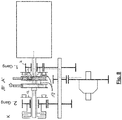
- FIG. 1 shows a jaw-connected gear 1 with two independently movable positive-locking elements A, B, which are designed here as sliding sleeves.
- the two sliding sleeves A, B are rotatably but slidably mounted on a drive shaft 2.
- the Drive shaft 2 is driven by a drive motor 3, in which it is z. B. may be an electric motor.
- a first gear 4 and a second gear 5 are rotatably arranged.
- a countershaft / output shaft 6 is arranged.
- a third gear 7 is rotatably disposed, which meshes with the first gear 4.
- a fourth gear 8 is rotatably disposed on the countershaft / output shaft 6, which meshes with the second gear 5.
- the first positive locking element formed by the sliding sleeve A rotatably and slidably disposed on the drive shaft 2.
- first shift position (open position) of the sliding sleeve A this is decoupled from the first gear 4.
- the first gear 4 can thus rotate independently of the sliding sleeve A and the thus rotatably coupled drive shaft 2.
- a freewheel 9 is arranged, which can be brought by moving the sliding sleeve A to the right into engagement with a form-locking element 10 of the first gear 4, which will be explained later in more detail.
- the second form-locking element B formed by the second sliding sleeve B is arranged rotatably and displaceably on the drive shaft 2.
- the clutch K has a first coupling element 11 (outer disk carrier), which is non-rotatably connected to the second gear 5, and a second Coupling element 12 (inner disk carrier), which can be rotationally coupled by moving the second sliding sleeve B with this.
- an output gear 13 is arranged, which meshes with a drive wheel 14 of a differential gear 15, which has a left output shaft 16 and a right output shaft 17.
- FIG. 2 shows the operating state in which the first gear is engaged.
- the sliding sleeve A is in a shift position shifted to the right, in which the freewheel 9 is in engagement with the first gear 4.
- the second shift sleeve B is also shifted to the right in a shift position, which is referred to as "first shift position".
- first shift position In the first switching position of the sliding sleeve B is a positive connection element 18 of the second sliding sleeve B in engagement with the first gear 4.
- the positive locking element 18 of the second sliding sleeve B passes through the first sliding sleeve A.
- the first gear in both directions with the second sliding sleeve B and thus rotatably coupled to the drive shaft 2, ie both in overrun mode and in train operation.
- FIG. 3 shows an operating state in which a gear change from the first to the second gear is prepared.
- the clutch K is opened, unless it was already open anyway.
- the sliding sleeve B is moved to the left, in a position in which the Positive locking element 18 of the sliding sleeve B disengaged, that is no longer in engagement with the first gear 4 is.
- FIG. 4 shows the phase of the engagement of the second gear, ie the phase of the torque transfer from the first gear to the second gear. This is done by closing the clutch K. As indicated by the dashed line, the torque flow takes place with second gear engaged, ie with the clutch K, from the drive shaft 2 via the sliding sleeve B to the second coupling element 12 and from this via the first coupling element 13 on the second gear 5 and from this to the fourth gear. 8
- FIG. 4 it can be seen, in this phase, the sliding sleeve A is still in its right switching position (second switching position), in which the freewheel 9 is still in engagement with the first gear 4. Since in the second gear at the same drive motor speed, the countershaft / output shaft 6 rotates faster than in the first gear, and the first gear 4 rotates correspondingly faster than the drive shaft 2. This is made possible by the freewheel 9. The freewheel 9 thus allows the first gear 4 to "overtake" the drive shaft 2 with respect to its rotational speed.
- FIG. 5 shows the completion of the gear change from first gear to second gear.
- the sliding sleeve A in their already in FIG. 1 shown shifted first position to the left, in which the freewheel 9 is decoupled from the first gear 4.
- FIG. 6 shows the preparation of a downshift, ie a shift from second gear to first gear.
- the sliding sleeve A is first moved to the right in its second switching position.
- the freewheel 9 is brought into engagement with the first gear 4. Since the first gear 4 is driven by the third gear 7, the first gear 4 rotates faster than the drive shaft 2.
- the freewheel 9 is thus in the freewheeling state, which allows the already mentioned above overtaking the drive shaft 2 by the first gear 4.
- FIG. 7 shows the next phase of the downshift.
- the clutch K is opened, which causes the freewheel is "overtaken", ie that the freewheel takes over the torque transmission.
- the sliding sleeve B moved to the right.
- the second coupling element 12 is decoupled from the sliding sleeve B and the interlocking element 18 of the sliding sleeve B is locked to the first gear 4.
- the actuation of the sliding sleeves A, B can, for. B. done electromechanically by servo motors.
- a hydraulic actuation of the sliding sleeves by means of a system with a hydraulic pressure accumulator would be conceivable.
- a hydraulic system with a pressure accumulator would be significantly more efficient.
- the loss of friction during normal operation in first gear or in second gear can be minimized. This is achieved by using the lossy elements "clutch” and “freewheel” only during the shifts and the number of gearing interventions is minimal.
- these can be switched by means of simple directional control valves. A fine adjustment is not required. Even with a failure of the Kupplungsaktutechnik circuits are still possible with traction interruption. Thus, a high system availability is guaranteed.
Claims (6)
- Boîte de vitesse commutable en charge (1) comprenant :- un arbre d'entraînement (2),- un premier pignon (4) et un second pignon (5) montés respectivement à rotation sur l'arbre d'entraînement (2),- un arbre intermédiaire/arbre de sortie (6),- un troisième pignon (7) solidaire en rotation de l'arbre intermédiaire/arbre de sortie (6) et en prise avec le premier pignon (4),- un quatrième pignon (8) solidaire en rotation de l'arbre intermédiaire/arbre de sortie (6) et en prise avec le second pignon (5),- un premier élément liaison par la forme (A) monté solidaire en rotation et coulissant sur l'arbre d'entraînement (2), et qui• dans une première position de commutation, est découplé du premier pignon (4), et• dans une seconde position de commutation, est couplé en rotation avec le premier pignon (4),le premier élément de liaison par la forme (A), dans la seconde position de commutation, est- couplé en rotation au premier pignon (4) dans le premier sens de rotation de ce premier pignon (4), et- dans un second sens de rotation, opposé au premier sens de rotation du premier pignon (4), cet élément est découplé du premier pignons denté (4) par un dispositif à roue libre (9), etil est prévu un second élément de liaison par le forme (B) solidaire en rotation et coulissant sur l'arbre d'entraînement et le second élément de liaison par la forme (B) peut prendre une première position commutation dans laquelle il est solidaire en rotation du premier pignon denté (4), boîte caractérisée en ce que
le second élément de liaison par le forme (B) dans la première position commutation, chevauche ou traverse le premier élément de liaison par la forme (A). - Boîte de vitesse commutable en charge selon la revendication 1, caractérisée en ce que
le dispositif de roue libre (9) est prévu sur le premier élément de liaison par la forme (A) et dans la seconde position de commutation il est en prise avec le premier pignon (4). - Boîte de vitesse commutable en charge selon la revendication 1,
caractérisée en ce qu'
il est prévu un embrayage (K) qui comporte un premier élément d'embrayage (11) solidaire en rotation du second pignon (5) et un second élément d'embrayage (12). - Boîte de vitesse commutable en charge selon l'une des revendications 1 à 3,
caractérisée en ce que
le second élément de liaison par la forme (B) peut prendre une seconde position de commutation dans laquelle il est découplé du premier pignon (4) et couplé solidairement en rotation avec le second élément d'embrayage (12). - Boîte de vitesse commutable en charge selon l'une des revendications 1 à 4,
caractérisée en ce qu'
il est prévu un moteur électrique (3) pour entrer l'arbre d'entraînement (2). - Boîte de vitesse commutable en charge selon l'une des revendications 1 à 5,
caractérisée en ce que
l'arbre intermédiaire/arbre de transmission (6) comporte un cinquième pignon (13) en prise avec le pignon d'entraînement (14) d'un différentiel (15).
Applications Claiming Priority (2)
| Application Number | Priority Date | Filing Date | Title |
|---|---|---|---|
| DE102013207413.1A DE102013207413B4 (de) | 2013-04-24 | 2013-04-24 | Lastschaltgetriebe, insbesondere für Elektroantriebe |
| PCT/EP2014/056764 WO2014173651A1 (fr) | 2013-04-24 | 2014-04-04 | Boîte de vitesses couplable sous charge, destinée en particulier à des entraînements électriques |
Publications (2)
| Publication Number | Publication Date |
|---|---|
| EP2989348A1 EP2989348A1 (fr) | 2016-03-02 |
| EP2989348B1 true EP2989348B1 (fr) | 2019-11-06 |
Family
ID=50434202
Family Applications (1)
| Application Number | Title | Priority Date | Filing Date |
|---|---|---|---|
| EP14715014.8A Active EP2989348B1 (fr) | 2013-04-24 | 2014-04-04 | Boîte de vitesses couplable sous charge, destinée en particulier à des entraînements électriques |
Country Status (3)
| Country | Link |
|---|---|
| EP (1) | EP2989348B1 (fr) |
| DE (1) | DE102013207413B4 (fr) |
| WO (1) | WO2014173651A1 (fr) |
Families Citing this family (10)
| Publication number | Priority date | Publication date | Assignee | Title |
|---|---|---|---|---|
| DE102015110839A1 (de) * | 2015-07-06 | 2017-01-12 | Dr. Ing. H.C. F. Porsche Aktiengesellschaft | Elektrischer Achsantrieb für ein Kraftfahrzeug |
| CN105041988A (zh) * | 2015-08-25 | 2015-11-11 | 重庆青山工业有限责任公司 | 一种两档纯电动汽车变速器 |
| DE102016205491A1 (de) * | 2016-04-04 | 2017-10-05 | Zf Friedrichshafen Ag | Getriebeanordnung zum Antrieb eines Kraftfahrzeugs |
| CN105864368B (zh) * | 2016-06-24 | 2018-02-13 | 包凯 | 一种电动车无动力中断换挡变速箱及其换挡控制方法 |
| CN106114202A (zh) * | 2016-07-26 | 2016-11-16 | 连云港北方变速器有限责任公司 | 电动汽车两档amt后桥总成 |
| CN108131426A (zh) * | 2017-11-17 | 2018-06-08 | 南京航空航天大学 | 一种摩擦片离合器式两级自动换挡变扭齿轮机构 |
| DE102018129269A1 (de) | 2017-12-06 | 2019-06-27 | Schaeffler Technologies AG & Co. KG | Geteilte Schiebemuffe |
| DE102019202015A1 (de) | 2019-02-14 | 2020-08-20 | Robert Bosch Gmbh | Lastschaltbares Mehr-Gang-Getriebe mit Freilauf |
| DE102019121735B3 (de) * | 2019-08-13 | 2020-12-17 | Iav Gmbh Ingenieurgesellschaft Auto Und Verkehr | Fahrzeugantrieb mit einer elektrischen Maschine und Untersetzungsgetriebe |
| CN113771608B (zh) * | 2021-09-26 | 2023-04-14 | 东莞市零越传动科技有限公司 | 用于电动车辆的驱动系统 |
Citations (2)
| Publication number | Priority date | Publication date | Assignee | Title |
|---|---|---|---|---|
| DE967545C (de) * | 1953-10-13 | 1957-11-21 | Georg Heim | Zahnraederwechselgetriebe, insbesondere fuer Kraftfahrzeuge mit Verbrennungsmotoren |
| DE10149173A1 (de) * | 2001-10-04 | 2003-04-17 | Werenfrid Doepper | Verbindungsglied (Kupplungselement)zur torsionsmomentenunterbrechungsfreien Übersetzungsumschaltung in Getrieben |
Family Cites Families (11)
| Publication number | Priority date | Publication date | Assignee | Title |
|---|---|---|---|---|
| DE218543C (fr) * | ||||
| GB363772A (en) * | 1930-10-30 | 1931-12-31 | Egon Neurath | Speed-changing mechanism for motor car gearings |
| DE969740C (de) * | 1953-11-10 | 1958-07-10 | Georg Heim | Zahnraederwechselgetriebe, insbesondere fuer Kraftfahrzeuge mit Verbrennungsmotoren |
| FR1420205A (fr) * | 1965-01-09 | 1965-12-03 | Enclenchement des rapports par roues libres sur boîte à vitesse mécanique | |
| JPH08226501A (ja) * | 1995-02-20 | 1996-09-03 | Toyota Motor Corp | 自動変速機 |
| DE19824415A1 (de) | 1998-05-30 | 1999-12-02 | Volkswagen Ag | Doppelwellengetriebe und ein Verfahren zu dessen Betrieb |
| DE10037398A1 (de) | 2000-08-01 | 2002-02-14 | Daimler Chrysler Ag | Zahnräderwechselgetriebe |
| FR2819570B1 (fr) * | 2001-01-16 | 2003-04-11 | Renault | Boite de vitesses a commande robotisee de vehicule automobile et procede de gestion d'une unite electronique de commande d'une telle boite |
| GB0702548D0 (en) * | 2007-02-09 | 2007-03-21 | Zeroshift Ltd | Gearbox |
| FR2946293B1 (fr) * | 2009-06-08 | 2013-01-25 | Renault Sas | Groupe motopropulseur pour vehicule electrique a trois arbres permettant d'obtenir deux rapports de transmission |
| DE102011112091A1 (de) | 2011-09-02 | 2013-03-07 | Lsp Innovative Automotive Systems Gmbh | Elektrisches Antriebssystem für ein batteriegetriebenes Leichtfahrzeug |
-
2013
- 2013-04-24 DE DE102013207413.1A patent/DE102013207413B4/de active Active
-
2014
- 2014-04-04 WO PCT/EP2014/056764 patent/WO2014173651A1/fr active Application Filing
- 2014-04-04 EP EP14715014.8A patent/EP2989348B1/fr active Active
Patent Citations (2)
| Publication number | Priority date | Publication date | Assignee | Title |
|---|---|---|---|---|
| DE967545C (de) * | 1953-10-13 | 1957-11-21 | Georg Heim | Zahnraederwechselgetriebe, insbesondere fuer Kraftfahrzeuge mit Verbrennungsmotoren |
| DE10149173A1 (de) * | 2001-10-04 | 2003-04-17 | Werenfrid Doepper | Verbindungsglied (Kupplungselement)zur torsionsmomentenunterbrechungsfreien Übersetzungsumschaltung in Getrieben |
Also Published As
| Publication number | Publication date |
|---|---|
| DE102013207413A1 (de) | 2014-10-30 |
| EP2989348A1 (fr) | 2016-03-02 |
| DE102013207413B4 (de) | 2017-03-30 |
| WO2014173651A1 (fr) | 2014-10-30 |
Similar Documents
| Publication | Publication Date | Title |
|---|---|---|
| EP2989348B1 (fr) | Boîte de vitesses couplable sous charge, destinée en particulier à des entraînements électriques | |
| EP1781968B1 (fr) | Boite de vitesses couplable sous charge, et procede de couplage correspondant | |
| DE2342771C2 (de) | Wechselgetriebe mit Bereichsumschaltung | |
| DE4400701C2 (de) | Übertragungsvorrichtung zur Übertragung einer Motorleistung auf Antriebsräder eines Fahrzeuges | |
| EP2652363B1 (fr) | Procédé permettant de faire fonctionner un dispositif de transmission de la chaîne cinématique d'un véhicule | |
| WO2006056326A1 (fr) | Ensemble actionneur avec commutateurs a cames pour une boite de vitesses a embrayage double | |
| WO2015014453A1 (fr) | Boîte de vitesses pour unité d'entraînement d'un véhicule électrique et procédé pour faire fonctionner la boîte de vitesse | |
| WO2018072780A1 (fr) | Boîte de vitesses à double embrayage | |
| DE102012206936A1 (de) | Hybridgetriebe | |
| DE102012209999B4 (de) | Doppelkupplungsgetriebe und Verfahren zum Schalten eines Doppelkupplungsgetriebes | |
| WO2008092566A1 (fr) | Mécanisme de changement de vitesses à double embrayage | |
| EP3679273A1 (fr) | Unité d'entraînement d'essieu comprenant une boîte de vitesses à deux rapports couplable sous charge | |
| WO2013139419A1 (fr) | Dispositif de chaîne cinématique de véhicule automobile comprenant une boîte de vitesses à plusieurs groupes | |
| DE112014000378T5 (de) | Getriebe für ein Fahrzeug und Fahrzeug mit einem derartigen Getriebe | |
| DE112014000456T5 (de) | Handschaltgetriebe | |
| WO2013127510A1 (fr) | Dispositif d'actionnement destiné à des boîtes de vitesses | |
| EP1002971B1 (fr) | Transmission pour véhicule automobile et procédé pour commander le changement de vitesse | |
| DE19930972C1 (de) | Verfahren zum Lastschalten eines Antriebsstranges, lastschaltbarer Antriebsstrang und Kupplungseinrichtung für einen lastschaltbaren Antriebsstrang | |
| DE102014115371B4 (de) | Schaltanordnung für ein Kraftfahrzeuggetriebe und Schaltverfahren | |
| AT512917B1 (de) | Verfahren zum Betreiben eines Doppelkupplungsgetriebes | |
| WO2003085287A2 (fr) | Transmission à changement de vitesses sous charge et procédé de commande d'une transmission à double embrayage | |
| DE102010024768A1 (de) | Kraftfahrzeuggruppengetriebevorrichtung | |
| DE102018220895A1 (de) | Antriebsanordnung für ein Fahrzeug mit zwei gleichwertigen Fahrtrichtungen und Verfahren | |
| DE102021130319B4 (de) | Steuervorrichtung und Verfahren zum Einlegen eines Startganges in einem Getriebe | |
| DE102011105065A1 (de) | Zweiwellenschaltgetriebe für ein Kraftfahrzeug |
Legal Events
| Date | Code | Title | Description |
|---|---|---|---|
| PUAI | Public reference made under article 153(3) epc to a published international application that has entered the european phase |
Free format text: ORIGINAL CODE: 0009012 |
|
| 17P | Request for examination filed |
Effective date: 20150730 |
|
| AK | Designated contracting states |
Kind code of ref document: A1 Designated state(s): AL AT BE BG CH CY CZ DE DK EE ES FI FR GB GR HR HU IE IS IT LI LT LU LV MC MK MT NL NO PL PT RO RS SE SI SK SM TR |
|
| AX | Request for extension of the european patent |
Extension state: BA ME |
|
| DAX | Request for extension of the european patent (deleted) | ||
| STAA | Information on the status of an ep patent application or granted ep patent |
Free format text: STATUS: EXAMINATION IS IN PROGRESS |
|
| 17Q | First examination report despatched |
Effective date: 20181126 |
|
| GRAP | Despatch of communication of intention to grant a patent |
Free format text: ORIGINAL CODE: EPIDOSNIGR1 |
|
| STAA | Information on the status of an ep patent application or granted ep patent |
Free format text: STATUS: GRANT OF PATENT IS INTENDED |
|
| INTG | Intention to grant announced |
Effective date: 20190724 |
|
| GRAS | Grant fee paid |
Free format text: ORIGINAL CODE: EPIDOSNIGR3 |
|
| GRAA | (expected) grant |
Free format text: ORIGINAL CODE: 0009210 |
|
| STAA | Information on the status of an ep patent application or granted ep patent |
Free format text: STATUS: THE PATENT HAS BEEN GRANTED |
|
| AK | Designated contracting states |
Kind code of ref document: B1 Designated state(s): AL AT BE BG CH CY CZ DE DK EE ES FI FR GB GR HR HU IE IS IT LI LT LU LV MC MK MT NL NO PL PT RO RS SE SI SK SM TR |
|
| REG | Reference to a national code |
Ref country code: GB Ref legal event code: FG4D Free format text: NOT ENGLISH |
|
| REG | Reference to a national code |
Ref country code: CH Ref legal event code: EP Ref country code: AT Ref legal event code: REF Ref document number: 1199144 Country of ref document: AT Kind code of ref document: T Effective date: 20191115 |
|
| REG | Reference to a national code |
Ref country code: IE Ref legal event code: FG4D Free format text: LANGUAGE OF EP DOCUMENT: GERMAN |
|
| REG | Reference to a national code |
Ref country code: DE Ref legal event code: R096 Ref document number: 502014013000 Country of ref document: DE |
|
| REG | Reference to a national code |
Ref country code: NL Ref legal event code: MP Effective date: 20191106 |
|
| REG | Reference to a national code |
Ref country code: LT Ref legal event code: MG4D |
|
| PG25 | Lapsed in a contracting state [announced via postgrant information from national office to epo] |
Ref country code: FI Free format text: LAPSE BECAUSE OF FAILURE TO SUBMIT A TRANSLATION OF THE DESCRIPTION OR TO PAY THE FEE WITHIN THE PRESCRIBED TIME-LIMIT Effective date: 20191106 Ref country code: BG Free format text: LAPSE BECAUSE OF FAILURE TO SUBMIT A TRANSLATION OF THE DESCRIPTION OR TO PAY THE FEE WITHIN THE PRESCRIBED TIME-LIMIT Effective date: 20200206 Ref country code: NO Free format text: LAPSE BECAUSE OF FAILURE TO SUBMIT A TRANSLATION OF THE DESCRIPTION OR TO PAY THE FEE WITHIN THE PRESCRIBED TIME-LIMIT Effective date: 20200206 Ref country code: GR Free format text: LAPSE BECAUSE OF FAILURE TO SUBMIT A TRANSLATION OF THE DESCRIPTION OR TO PAY THE FEE WITHIN THE PRESCRIBED TIME-LIMIT Effective date: 20200207 Ref country code: LT Free format text: LAPSE BECAUSE OF FAILURE TO SUBMIT A TRANSLATION OF THE DESCRIPTION OR TO PAY THE FEE WITHIN THE PRESCRIBED TIME-LIMIT Effective date: 20191106 Ref country code: NL Free format text: LAPSE BECAUSE OF FAILURE TO SUBMIT A TRANSLATION OF THE DESCRIPTION OR TO PAY THE FEE WITHIN THE PRESCRIBED TIME-LIMIT Effective date: 20191106 Ref country code: PL Free format text: LAPSE BECAUSE OF FAILURE TO SUBMIT A TRANSLATION OF THE DESCRIPTION OR TO PAY THE FEE WITHIN THE PRESCRIBED TIME-LIMIT Effective date: 20191106 Ref country code: PT Free format text: LAPSE BECAUSE OF FAILURE TO SUBMIT A TRANSLATION OF THE DESCRIPTION OR TO PAY THE FEE WITHIN THE PRESCRIBED TIME-LIMIT Effective date: 20200306 Ref country code: LV Free format text: LAPSE BECAUSE OF FAILURE TO SUBMIT A TRANSLATION OF THE DESCRIPTION OR TO PAY THE FEE WITHIN THE PRESCRIBED TIME-LIMIT Effective date: 20191106 Ref country code: SE Free format text: LAPSE BECAUSE OF FAILURE TO SUBMIT A TRANSLATION OF THE DESCRIPTION OR TO PAY THE FEE WITHIN THE PRESCRIBED TIME-LIMIT Effective date: 20191106 |
|
| PG25 | Lapsed in a contracting state [announced via postgrant information from national office to epo] |
Ref country code: IS Free format text: LAPSE BECAUSE OF FAILURE TO SUBMIT A TRANSLATION OF THE DESCRIPTION OR TO PAY THE FEE WITHIN THE PRESCRIBED TIME-LIMIT Effective date: 20200306 Ref country code: RS Free format text: LAPSE BECAUSE OF FAILURE TO SUBMIT A TRANSLATION OF THE DESCRIPTION OR TO PAY THE FEE WITHIN THE PRESCRIBED TIME-LIMIT Effective date: 20191106 Ref country code: HR Free format text: LAPSE BECAUSE OF FAILURE TO SUBMIT A TRANSLATION OF THE DESCRIPTION OR TO PAY THE FEE WITHIN THE PRESCRIBED TIME-LIMIT Effective date: 20191106 |
|
| PG25 | Lapsed in a contracting state [announced via postgrant information from national office to epo] |
Ref country code: AL Free format text: LAPSE BECAUSE OF FAILURE TO SUBMIT A TRANSLATION OF THE DESCRIPTION OR TO PAY THE FEE WITHIN THE PRESCRIBED TIME-LIMIT Effective date: 20191106 |
|
| PG25 | Lapsed in a contracting state [announced via postgrant information from national office to epo] |
Ref country code: ES Free format text: LAPSE BECAUSE OF FAILURE TO SUBMIT A TRANSLATION OF THE DESCRIPTION OR TO PAY THE FEE WITHIN THE PRESCRIBED TIME-LIMIT Effective date: 20191106 Ref country code: DK Free format text: LAPSE BECAUSE OF FAILURE TO SUBMIT A TRANSLATION OF THE DESCRIPTION OR TO PAY THE FEE WITHIN THE PRESCRIBED TIME-LIMIT Effective date: 20191106 Ref country code: RO Free format text: LAPSE BECAUSE OF FAILURE TO SUBMIT A TRANSLATION OF THE DESCRIPTION OR TO PAY THE FEE WITHIN THE PRESCRIBED TIME-LIMIT Effective date: 20191106 Ref country code: CZ Free format text: LAPSE BECAUSE OF FAILURE TO SUBMIT A TRANSLATION OF THE DESCRIPTION OR TO PAY THE FEE WITHIN THE PRESCRIBED TIME-LIMIT Effective date: 20191106 Ref country code: EE Free format text: LAPSE BECAUSE OF FAILURE TO SUBMIT A TRANSLATION OF THE DESCRIPTION OR TO PAY THE FEE WITHIN THE PRESCRIBED TIME-LIMIT Effective date: 20191106 |
|
| REG | Reference to a national code |
Ref country code: DE Ref legal event code: R097 Ref document number: 502014013000 Country of ref document: DE |
|
| PG25 | Lapsed in a contracting state [announced via postgrant information from national office to epo] |
Ref country code: SK Free format text: LAPSE BECAUSE OF FAILURE TO SUBMIT A TRANSLATION OF THE DESCRIPTION OR TO PAY THE FEE WITHIN THE PRESCRIBED TIME-LIMIT Effective date: 20191106 Ref country code: SM Free format text: LAPSE BECAUSE OF FAILURE TO SUBMIT A TRANSLATION OF THE DESCRIPTION OR TO PAY THE FEE WITHIN THE PRESCRIBED TIME-LIMIT Effective date: 20191106 |
|
| PLBE | No opposition filed within time limit |
Free format text: ORIGINAL CODE: 0009261 |
|
| STAA | Information on the status of an ep patent application or granted ep patent |
Free format text: STATUS: NO OPPOSITION FILED WITHIN TIME LIMIT |
|
| 26N | No opposition filed |
Effective date: 20200807 |
|
| PG25 | Lapsed in a contracting state [announced via postgrant information from national office to epo] |
Ref country code: SI Free format text: LAPSE BECAUSE OF FAILURE TO SUBMIT A TRANSLATION OF THE DESCRIPTION OR TO PAY THE FEE WITHIN THE PRESCRIBED TIME-LIMIT Effective date: 20191106 Ref country code: MC Free format text: LAPSE BECAUSE OF FAILURE TO SUBMIT A TRANSLATION OF THE DESCRIPTION OR TO PAY THE FEE WITHIN THE PRESCRIBED TIME-LIMIT Effective date: 20191106 |
|
| REG | Reference to a national code |
Ref country code: CH Ref legal event code: PL |
|
| PG25 | Lapsed in a contracting state [announced via postgrant information from national office to epo] |
Ref country code: LU Free format text: LAPSE BECAUSE OF NON-PAYMENT OF DUE FEES Effective date: 20200404 Ref country code: CH Free format text: LAPSE BECAUSE OF NON-PAYMENT OF DUE FEES Effective date: 20200430 Ref country code: LI Free format text: LAPSE BECAUSE OF NON-PAYMENT OF DUE FEES Effective date: 20200430 |
|
| REG | Reference to a national code |
Ref country code: BE Ref legal event code: MM Effective date: 20200430 |
|
| PG25 | Lapsed in a contracting state [announced via postgrant information from national office to epo] |
Ref country code: BE Free format text: LAPSE BECAUSE OF NON-PAYMENT OF DUE FEES Effective date: 20200430 |
|
| PG25 | Lapsed in a contracting state [announced via postgrant information from national office to epo] |
Ref country code: IE Free format text: LAPSE BECAUSE OF NON-PAYMENT OF DUE FEES Effective date: 20200404 |
|
| REG | Reference to a national code |
Ref country code: AT Ref legal event code: MM01 Ref document number: 1199144 Country of ref document: AT Kind code of ref document: T Effective date: 20200404 |
|
| PG25 | Lapsed in a contracting state [announced via postgrant information from national office to epo] |
Ref country code: AT Free format text: LAPSE BECAUSE OF NON-PAYMENT OF DUE FEES Effective date: 20200404 |
|
| PG25 | Lapsed in a contracting state [announced via postgrant information from national office to epo] |
Ref country code: TR Free format text: LAPSE BECAUSE OF FAILURE TO SUBMIT A TRANSLATION OF THE DESCRIPTION OR TO PAY THE FEE WITHIN THE PRESCRIBED TIME-LIMIT Effective date: 20191106 Ref country code: MT Free format text: LAPSE BECAUSE OF FAILURE TO SUBMIT A TRANSLATION OF THE DESCRIPTION OR TO PAY THE FEE WITHIN THE PRESCRIBED TIME-LIMIT Effective date: 20191106 Ref country code: CY Free format text: LAPSE BECAUSE OF FAILURE TO SUBMIT A TRANSLATION OF THE DESCRIPTION OR TO PAY THE FEE WITHIN THE PRESCRIBED TIME-LIMIT Effective date: 20191106 |
|
| PG25 | Lapsed in a contracting state [announced via postgrant information from national office to epo] |
Ref country code: MK Free format text: LAPSE BECAUSE OF FAILURE TO SUBMIT A TRANSLATION OF THE DESCRIPTION OR TO PAY THE FEE WITHIN THE PRESCRIBED TIME-LIMIT Effective date: 20191106 |
|
| P01 | Opt-out of the competence of the unified patent court (upc) registered |
Effective date: 20230502 |
|
| PGFP | Annual fee paid to national office [announced via postgrant information from national office to epo] |
Ref country code: IT Payment date: 20230428 Year of fee payment: 10 Ref country code: FR Payment date: 20230417 Year of fee payment: 10 Ref country code: DE Payment date: 20230411 Year of fee payment: 10 |
|
| PGFP | Annual fee paid to national office [announced via postgrant information from national office to epo] |
Ref country code: GB Payment date: 20230420 Year of fee payment: 10 |