EP2989227B1 - Outil revêtu par dépôt chimique en phase vapeur - Google Patents
Outil revêtu par dépôt chimique en phase vapeur Download PDFInfo
- Publication number
- EP2989227B1 EP2989227B1 EP14718568.0A EP14718568A EP2989227B1 EP 2989227 B1 EP2989227 B1 EP 2989227B1 EP 14718568 A EP14718568 A EP 14718568A EP 2989227 B1 EP2989227 B1 EP 2989227B1
- Authority
- EP
- European Patent Office
- Prior art keywords
- layer
- cvd
- range
- precursor gas
- vol
- Prior art date
- Legal status (The legal status is an assumption and is not a legal conclusion. Google has not performed a legal analysis and makes no representation as to the accuracy of the status listed.)
- Active
Links
- 238000000576 coating method Methods 0.000 title claims description 76
- 239000011248 coating agent Substances 0.000 title claims description 57
- 239000010410 layer Substances 0.000 claims description 105
- 239000007789 gas Substances 0.000 claims description 64
- 239000000203 mixture Substances 0.000 claims description 60
- 238000000034 method Methods 0.000 claims description 44
- 239000002243 precursor Substances 0.000 claims description 42
- 230000008569 process Effects 0.000 claims description 38
- ATJFFYVFTNAWJD-UHFFFAOYSA-N Tin Chemical compound [Sn] ATJFFYVFTNAWJD-UHFFFAOYSA-N 0.000 claims description 24
- QGZKDVFQNNGYKY-UHFFFAOYSA-N Ammonia Chemical compound N QGZKDVFQNNGYKY-UHFFFAOYSA-N 0.000 claims description 18
- 238000002441 X-ray diffraction Methods 0.000 claims description 16
- IJGRMHOSHXDMSA-UHFFFAOYSA-N Atomic nitrogen Chemical compound N#N IJGRMHOSHXDMSA-UHFFFAOYSA-N 0.000 claims description 14
- 238000005422 blasting Methods 0.000 claims description 14
- 239000000463 material Substances 0.000 claims description 14
- WEVYAHXRMPXWCK-UHFFFAOYSA-N Acetonitrile Chemical compound CC#N WEVYAHXRMPXWCK-UHFFFAOYSA-N 0.000 claims description 12
- 229910052593 corundum Inorganic materials 0.000 claims description 12
- 229910052757 nitrogen Inorganic materials 0.000 claims description 12
- OAKJQQAXSVQMHS-UHFFFAOYSA-N Hydrazine Chemical compound NN OAKJQQAXSVQMHS-UHFFFAOYSA-N 0.000 claims description 9
- UFHFLCQGNIYNRP-UHFFFAOYSA-N Hydrogen Chemical compound [H][H] UFHFLCQGNIYNRP-UHFFFAOYSA-N 0.000 claims description 8
- 229910000831 Steel Inorganic materials 0.000 claims description 8
- 239000010431 corundum Substances 0.000 claims description 8
- 229910052739 hydrogen Inorganic materials 0.000 claims description 8
- 239000001257 hydrogen Substances 0.000 claims description 8
- 238000004519 manufacturing process Methods 0.000 claims description 8
- 239000010959 steel Substances 0.000 claims description 8
- HSFWRNGVRCDJHI-UHFFFAOYSA-N Acetylene Chemical compound C#C HSFWRNGVRCDJHI-UHFFFAOYSA-N 0.000 claims description 7
- 229910021529 ammonia Inorganic materials 0.000 claims description 7
- 239000012159 carrier gas Substances 0.000 claims description 7
- 229910000997 High-speed steel Inorganic materials 0.000 claims description 6
- 239000000919 ceramic Substances 0.000 claims description 6
- 239000011195 cermet Substances 0.000 claims description 6
- 238000001887 electron backscatter diffraction Methods 0.000 claims description 5
- VSCWAEJMTAWNJL-UHFFFAOYSA-K aluminium trichloride Chemical compound Cl[Al](Cl)Cl VSCWAEJMTAWNJL-UHFFFAOYSA-K 0.000 claims description 4
- 239000003795 chemical substances by application Substances 0.000 claims description 4
- 150000002431 hydrogen Chemical class 0.000 claims description 4
- OTMSDBZUPAUEDD-UHFFFAOYSA-N Ethane Chemical compound CC OTMSDBZUPAUEDD-UHFFFAOYSA-N 0.000 claims description 3
- VGGSQFUCUMXWEO-UHFFFAOYSA-N Ethene Chemical compound C=C VGGSQFUCUMXWEO-UHFFFAOYSA-N 0.000 claims description 3
- 229910003074 TiCl4 Inorganic materials 0.000 claims description 3
- 239000002356 single layer Substances 0.000 claims description 3
- XJDNKRIXUMDJCW-UHFFFAOYSA-J titanium tetrachloride Chemical compound Cl[Ti](Cl)(Cl)Cl XJDNKRIXUMDJCW-UHFFFAOYSA-J 0.000 claims description 3
- 238000012986 modification Methods 0.000 claims description 2
- 230000004048 modification Effects 0.000 claims description 2
- PNEYBMLMFCGWSK-UHFFFAOYSA-N aluminium oxide Inorganic materials [O-2].[O-2].[O-2].[Al+3].[Al+3] PNEYBMLMFCGWSK-UHFFFAOYSA-N 0.000 claims 4
- 229910001845 yogo sapphire Inorganic materials 0.000 claims 4
- 229910000069 nitrogen hydride Inorganic materials 0.000 claims 2
- 229910052594 sapphire Inorganic materials 0.000 claims 2
- 229910003158 γ-Al2O3 Inorganic materials 0.000 claims 1
- 238000005229 chemical vapour deposition Methods 0.000 description 38
- 238000005520 cutting process Methods 0.000 description 32
- 230000035882 stress Effects 0.000 description 22
- 239000013078 crystal Substances 0.000 description 13
- 238000005259 measurement Methods 0.000 description 13
- 238000003801 milling Methods 0.000 description 11
- 229910018072 Al 2 O 3 Inorganic materials 0.000 description 10
- 229910052751 metal Inorganic materials 0.000 description 10
- 239000002184 metal Substances 0.000 description 10
- 239000000835 fiber Substances 0.000 description 8
- 239000000758 substrate Substances 0.000 description 8
- 238000000151 deposition Methods 0.000 description 6
- 230000008021 deposition Effects 0.000 description 6
- 238000002149 energy-dispersive X-ray emission spectroscopy Methods 0.000 description 6
- 238000002360 preparation method Methods 0.000 description 6
- 239000002245 particle Substances 0.000 description 5
- 238000005240 physical vapour deposition Methods 0.000 description 5
- 230000000052 comparative effect Effects 0.000 description 4
- 238000003754 machining Methods 0.000 description 4
- 238000012360 testing method Methods 0.000 description 4
- 238000007514 turning Methods 0.000 description 4
- 229910052782 aluminium Inorganic materials 0.000 description 3
- 238000002474 experimental method Methods 0.000 description 3
- 230000010354 integration Effects 0.000 description 3
- 230000001360 synchronised effect Effects 0.000 description 3
- 229910001060 Gray iron Inorganic materials 0.000 description 2
- PXHVJJICTQNCMI-UHFFFAOYSA-N Nickel Chemical compound [Ni] PXHVJJICTQNCMI-UHFFFAOYSA-N 0.000 description 2
- 229910010037 TiAlN Inorganic materials 0.000 description 2
- 238000004458 analytical method Methods 0.000 description 2
- 238000013459 approach Methods 0.000 description 2
- 230000008901 benefit Effects 0.000 description 2
- 239000000460 chlorine Substances 0.000 description 2
- 150000001805 chlorine compounds Chemical class 0.000 description 2
- 238000009826 distribution Methods 0.000 description 2
- 150000002739 metals Chemical class 0.000 description 2
- 238000005555 metalworking Methods 0.000 description 2
- 230000002441 reversible effect Effects 0.000 description 2
- 239000007858 starting material Substances 0.000 description 2
- ZAMOUSCENKQFHK-UHFFFAOYSA-N Chlorine atom Chemical compound [Cl] ZAMOUSCENKQFHK-UHFFFAOYSA-N 0.000 description 1
- 229910001141 Ductile iron Inorganic materials 0.000 description 1
- 241000976924 Inca Species 0.000 description 1
- 229910001209 Low-carbon steel Inorganic materials 0.000 description 1
- 238000005299 abrasion Methods 0.000 description 1
- 230000001133 acceleration Effects 0.000 description 1
- 230000006978 adaptation Effects 0.000 description 1
- XAGFODPZIPBFFR-UHFFFAOYSA-N aluminium Chemical compound [Al] XAGFODPZIPBFFR-UHFFFAOYSA-N 0.000 description 1
- 230000015572 biosynthetic process Effects 0.000 description 1
- 238000004364 calculation method Methods 0.000 description 1
- 230000008859 change Effects 0.000 description 1
- 229910052801 chlorine Inorganic materials 0.000 description 1
- 230000009918 complex formation Effects 0.000 description 1
- 239000002826 coolant Substances 0.000 description 1
- 238000001816 cooling Methods 0.000 description 1
- 238000012937 correction Methods 0.000 description 1
- 230000007423 decrease Effects 0.000 description 1
- 238000005315 distribution function Methods 0.000 description 1
- 230000000694 effects Effects 0.000 description 1
- 238000002003 electron diffraction Methods 0.000 description 1
- 239000000839 emulsion Substances 0.000 description 1
- 238000005516 engineering process Methods 0.000 description 1
- 239000012530 fluid Substances 0.000 description 1
- 230000004941 influx Effects 0.000 description 1
- 238000007689 inspection Methods 0.000 description 1
- 238000002156 mixing Methods 0.000 description 1
- 229910052759 nickel Inorganic materials 0.000 description 1
- 229910017464 nitrogen compound Inorganic materials 0.000 description 1
- 150000002830 nitrogen compounds Chemical class 0.000 description 1
- TWNQGVIAIRXVLR-UHFFFAOYSA-N oxo(oxoalumanyloxy)alumane Chemical compound O=[Al]O[Al]=O TWNQGVIAIRXVLR-UHFFFAOYSA-N 0.000 description 1
- 238000000623 plasma-assisted chemical vapour deposition Methods 0.000 description 1
- 230000010287 polarization Effects 0.000 description 1
- 238000000984 pole figure measurement Methods 0.000 description 1
- 238000012545 processing Methods 0.000 description 1
- 230000005855 radiation Effects 0.000 description 1
- 230000011514 reflex Effects 0.000 description 1
- 238000000926 separation method Methods 0.000 description 1
- 238000004901 spalling Methods 0.000 description 1
- 239000000126 substance Substances 0.000 description 1
- 230000008646 thermal stress Effects 0.000 description 1
- 230000000930 thermomechanical effect Effects 0.000 description 1
- 230000009466 transformation Effects 0.000 description 1
- 238000000844 transformation Methods 0.000 description 1
- 238000002424 x-ray crystallography Methods 0.000 description 1
Images

Classifications
-
- C—CHEMISTRY; METALLURGY
- C23—COATING METALLIC MATERIAL; COATING MATERIAL WITH METALLIC MATERIAL; CHEMICAL SURFACE TREATMENT; DIFFUSION TREATMENT OF METALLIC MATERIAL; COATING BY VACUUM EVAPORATION, BY SPUTTERING, BY ION IMPLANTATION OR BY CHEMICAL VAPOUR DEPOSITION, IN GENERAL; INHIBITING CORROSION OF METALLIC MATERIAL OR INCRUSTATION IN GENERAL
- C23C—COATING METALLIC MATERIAL; COATING MATERIAL WITH METALLIC MATERIAL; SURFACE TREATMENT OF METALLIC MATERIAL BY DIFFUSION INTO THE SURFACE, BY CHEMICAL CONVERSION OR SUBSTITUTION; COATING BY VACUUM EVAPORATION, BY SPUTTERING, BY ION IMPLANTATION OR BY CHEMICAL VAPOUR DEPOSITION, IN GENERAL
- C23C16/00—Chemical coating by decomposition of gaseous compounds, without leaving reaction products of surface material in the coating, i.e. chemical vapour deposition [CVD] processes
- C23C16/22—Chemical coating by decomposition of gaseous compounds, without leaving reaction products of surface material in the coating, i.e. chemical vapour deposition [CVD] processes characterised by the deposition of inorganic material, other than metallic material
- C23C16/30—Deposition of compounds, mixtures or solid solutions, e.g. borides, carbides, nitrides
- C23C16/34—Nitrides
-
- C—CHEMISTRY; METALLURGY
- C23—COATING METALLIC MATERIAL; COATING MATERIAL WITH METALLIC MATERIAL; CHEMICAL SURFACE TREATMENT; DIFFUSION TREATMENT OF METALLIC MATERIAL; COATING BY VACUUM EVAPORATION, BY SPUTTERING, BY ION IMPLANTATION OR BY CHEMICAL VAPOUR DEPOSITION, IN GENERAL; INHIBITING CORROSION OF METALLIC MATERIAL OR INCRUSTATION IN GENERAL
- C23C—COATING METALLIC MATERIAL; COATING MATERIAL WITH METALLIC MATERIAL; SURFACE TREATMENT OF METALLIC MATERIAL BY DIFFUSION INTO THE SURFACE, BY CHEMICAL CONVERSION OR SUBSTITUTION; COATING BY VACUUM EVAPORATION, BY SPUTTERING, BY ION IMPLANTATION OR BY CHEMICAL VAPOUR DEPOSITION, IN GENERAL
- C23C16/00—Chemical coating by decomposition of gaseous compounds, without leaving reaction products of surface material in the coating, i.e. chemical vapour deposition [CVD] processes
- C23C16/44—Chemical coating by decomposition of gaseous compounds, without leaving reaction products of surface material in the coating, i.e. chemical vapour deposition [CVD] processes characterised by the method of coating
- C23C16/455—Chemical coating by decomposition of gaseous compounds, without leaving reaction products of surface material in the coating, i.e. chemical vapour deposition [CVD] processes characterised by the method of coating characterised by the method used for introducing gases into reaction chamber or for modifying gas flows in reaction chamber
- C23C16/45502—Flow conditions in reaction chamber
- C23C16/45508—Radial flow
Definitions
- the invention relates to a tool having a base body made of hard metal, cermet, ceramic, steel or high-speed steel and a single or multi-layer wear protection coating applied thereon in the CVD method, wherein the wear protection coating has at least one Ti 1-x Al x C y N z layer with stoichiometry coefficients 0.70 ⁇ x ⁇ 1, 0 ⁇ y ⁇ 0.25 and 0.75 ⁇ z ⁇ 1.15 and having a crystallographic preferential orientation. Furthermore, the invention relates to a method for producing such a tool.
- Cutting inserts for material processing consist of a substrate body made of hard metal, cermet, ceramic, steel or high-speed steel, which is provided in most cases to improve the cutting and / or wear properties with a single or multi-layer hard coating.
- the hard material coating consists of superimposed layers of monometallic or mixed metallic hard material phases. Examples of monometallic hard material phases are TiN, TiC, TiCN and Al 2 O 3 . Examples of mixed metallic phases in which one metal is partially replaced by another in one crystal are TiAIN and TiAICN. Coatings of the aforementioned type are applied by CVD (chemical vapor deposition), PCVD (plasma assisted CVD) or PVD (physical vapor deposition).
- certain preferred orientations of the crystal growth in the deposition in the PVD or CVD process can have particular advantages, wherein for different applications of the cutting insert also different preferred orientations of certain layers of a coating can be particularly advantageous.
- the preference orientation of growth is usually in relation to the levels defined above the Miller indices of the crystal lattice and referred to as a crystallographic texture (eg, fiber texture).
- the DE 10 2005 032 860 discloses a hard coating having a face-centered cubic Ti 1-x Al x N layer with an Al content of 0.75 ⁇ x ⁇ 0.93 and a method of making the same.
- the DE 10 2007 000 512 discloses a hard coating with a layer of TiAIN deposited on a first layer of TiN, TiCN or TiC deposited directly on the substrate and a phase gradient bonding layer provided between the two layers.
- the TiAIN layer has a preferential orientation of crystal growth relative to the (200) plane of the crystal lattice.
- WO 2009/112115 disclose CVD-deposited TiAIN and TiAlCN layers with high Al content and cubic face-centered lattice, but no crystallographic preferential orientations of crystal growth are described.
- I. Endler et al. Describe in Surface & Coatings Technologhy 205 (210) 1307-1312 CVD method for aluminum-rich TiAlCN coatings, which have a preferred orientation of ⁇ 111 ⁇ and ⁇ 200 ⁇ planes.
- TiAIN coatings with various crystalline crystallographic preferences of crystal growth produced by PVD processes are known, however, in contrast to CVD coatings, PVD coatings with cubic face-centered lattice of the TiAIN coatings are limited to Al contents of less than 67%.
- TiAIN coatings with a crystallographic preferential orientation of the ⁇ 200 ⁇ plane with respect to the growth direction of the crystallites are described as being advantageous for metalworking (eg. US 2009/0274899 . US 2009/0074521 and WO 2009/127344 ).
- the object of the present invention was to provide cutting inserts for metal cutting, in particular the turning and milling of steel or cast materials, which have a comparison with the prior art improved wear resistance.
- percentages by volume in the precursor gas mixtures relate to the total volume of the gas mixture introduced into the reaction zone from the first and second precursor gas mixtures.
- the process of the invention Ti 1-x Al x C y N z - and Ti 1-x Al x N z layers with stoichiometric 0.70 ⁇ x ⁇ 1, 0 ⁇ y ⁇ 0.25 and 0.75 ⁇ z ⁇ 1.15 and can be made with face-centered cubic lattice having a pronounced orientation of crystal growth relative to the ⁇ 111 ⁇ plane of the crystal lattice.
- the coatings according to the invention have outstanding properties in metalworking. It has further been surprisingly found that in a cutting insert having a coating of the type described herein in metal cutting operations, particularly in turning and milling of steel or cast materials, improved wear resistance over a known cutting insert and a wider range of applications can be achieved.
- the CVD process of the present invention provides two precursor gas mixtures (VG1) and (VG2) wherein the first precursor gas mixture (VG1) contains the metals Ti and Al in the form of their chlorides and carrier gas and the second precursor gas mixture (VG2) contains at least one N-donor contains.
- the first precursor gas mixture (VG1) contains the metals Ti and Al in the form of their chlorides and carrier gas
- the second precursor gas mixture (VG2) contains at least one N-donor contains.
- N-donor ammonia (NH 3 ) or hydrazine (N 2 H 4 ) is used for the preparation TiAlCN layer
- N-donor and C-donor are used, for example, ammonia (NH 3 ) in admixture with ethene (C 2 H 4 ).
- Acetonitrile acts predominantly as a C donor in the process according to the invention and is therefore used in admixture with an N donor.
- N donor be supplied separately from the chlorides of the metals Ti and Al, while the C donor may be supplied via both the first precursor gas mixture (VG1) and the second precursor gas mixture (VG2).
- the N-donor is ammonia (NH 3 ).
- the inventively used CVD process is an MT-CVD process at a process temperature in the CVD reactor in the range of 600 ° C to 850 ° C and a process pressure in the range of 0.2 to 18 kPa.
- the CVD reactor is a substantially cylindrical reactor designed to flow the bodies to be coated with the process gases in a direction substantially radial to the longitudinal axis of the reactor, ie from the central axis of the cylindrical body Reactor in the direction of the outer wall of the reactor formed by the cylinder jacket.
- Such cylindrical reactors are known and commercially available, for example the Bernex® BPXpro CVD coating systems from lonbond AG Olten, Switzerland.
- An essential method of the process of the invention is that the two precursor gas mixtures (VG1) and (VG2) are kept separate prior to entering the reaction zone. If this is not done, the precursor gas streams may already react too early, for example in the supply lines, and the desired coating will not be achieved.
- Another essential method of the method according to the invention is that the ratio of the volume gas flows ( v ⁇ ) of the precursor gas mixtures (VG1, VG2) v ⁇ (VG1) / v ⁇ (VG2) is less than 1.5. If one selects the ratio of the volume gas flows ( v ⁇ ) of the precursor gas mixtures (VG1, VG2) v ⁇ (VG1) / v ⁇ (VG2) greater than 1.5, one does not obtain the desired properties of the Ti 1-x Al x C y N z layer in particular not the preferential orientation of crystal growth with respect to the ⁇ 111 ⁇ plane of the crystal lattice defined herein as the ratio of the intensities of the X-ray diffraction peaks I ⁇ 111 ⁇ / I ⁇ 200 ⁇ and according to the invention should be> 1+ h (In h) 2 where h is the thickness of the Ti 1-x Al x C y N z layer in " ⁇ m".
- the process temperature in the CVD reactor is in the range of 650 ° C to 800 ° C, preferably in the range of 675 ° C to 750 ° C.
- the process temperature in the CVD reactor is too low, the deposition rate may drop to an uneconomic level.
- layers with chlorine contents> 1 at.% And lower hardness are obtained at low temperatures.
- the process pressure in the CVD reactor is in the range from 0.2 to 7 kPa, preferably in the range from 0.4 to 1.8 kPa.
- the ratio of the volume gas flows ( v ⁇ ) of the precursor gas mixtures (VG1, VG2) v ⁇ (VG1) / v ⁇ (VG2) is less than 1.25, preferably less than 1.15.
- the concentration of TiCl 4 in the precursor gas mixture (VG1) and the concentration of nitrogen donor in the precursor gas mixture (VG2) are adjusted so that the molar ratio of Ti to N in the in step c) in the volume of the gas introduced by the reactor is v ⁇ (VG1) and v ⁇ (VG2) ⁇ 0.25.
- the volumetric gas streams v ⁇ (VG1) and v ⁇ (VG2) introduced into the reactor are given very Ti-rich layers, in particular when ammonia (NH 3 ) is used as N 2. donor. It is believed that if the ratio of Ti to N in the bulk gas streams is too high, the reaction of AlCl 3 is suppressed due to complex formation between TiCl 4 and the N donor.
- the second precursor gas mixture (VG2) contains ⁇ 1.0 vol .-%, preferably ⁇ 0.6 vol .-% of the N-donor.
- the concentration of the N-donor, optionally in admixture with C donor, in the second precursor gas mixture (VG2) is too high, the desired composition and crystallographic preferential orientation will not be obtained.
- the wear protection coating is subjected to a blasting treatment with a particulate blasting agent, preferably corundum, under conditions such that the Ti 1-x Al x C y N z layer after the blasting treatment has residual stresses in the range from +300 to -5000 MPa, preferably in the range of -1 to -3500 MPa.
- a particulate blasting agent preferably corundum
- the coating may flake off at the edges of the tool.
- the blast treatment is conveniently carried out at a fluid jet pressure of 1 bar to 10 bar.
- the duration of the jet treatment required for introducing the residual stresses according to the invention and the required jet pressure are parameters which the person skilled in the art can determine by simple experiments within the limits defined herein. A blanket statement is not possible here, since the self-adjusting residual stresses depend not only on the duration of the blast treatment and the jet pressure, but also on the structure and the thickness of the overall coating. However, the jet pressure has the much greater influence on the change in the residual stresses in the coating and the substrate body compared to the jet duration. Suitable jet treatment times are usually in the range of 10 to 600 seconds.
- the beam angle, d. H. the angle between the treatment beam and the surface of the tool also has a significant influence on the introduction of residual stresses. At a beam angle of 90 °, the maximum entry of compressive residual stresses occurs. Lower beam angles, d. H. oblique irradiation of the blasting abrasive, lead to a stronger abrasion of the surface and lower pressure self-tension entry.
- the invention also encompasses a tool having a base body made of cemented carbide, cermet, ceramic, steel or high-speed steel and a single-layer or multi-layer wear protection coating applied thereto by the CVD method, wherein the wear protection coating has at least one Ti 1-x Al x C y N z layer having stoichiometry coefficients 0.70 ⁇ x ⁇ 1, 0 ⁇ y ⁇ 0.25 and 0.75 ⁇ z ⁇ 1.15, characterized in that the Ti 1-x Al x C y N z layer has a thickness in the range of 1 ⁇ m to 25 ⁇ m and has a crystallographic preferential orientation characterized by a ratio of the intensities of the X-ray diffraction peaks of the ⁇ 111 ⁇ crystallographic plane and ⁇ 200 ⁇ Is characterized in that I ⁇ 111 ⁇ / I ⁇ 200 ⁇ > 1 + h (In h) 2 , where h is the thickness of the Ti 1-x Al x C y N z layer in "
- the half-width (FWHM) of the X-ray diffraction peak of the ⁇ 111 ⁇ plane of the Ti 1-x Al x C y N z layer is ⁇ 1 °, preferably ⁇ 0.6 °, particularly preferably ⁇ 0.45 °.
- Too high a full width at half maximum (FWHM) of the X-ray diffraction peak of the ⁇ 111 ⁇ plane of the Ti 1-x Al x C y N z layer indicates smaller grain sizes of the cubic face centered (fcc) phase or even portions of amorphous phases. This has proven in the previous tests as a disadvantage for the wear resistance.
- the Ti 1-x Al x C y N z layer has at least 90 vol.% Ti 1-x Al x C y N z phase with cubic face-centered (fcc) grating, preferably at least 95 Vol .-% Ti 1-x Al x C y N z phase with cubic face centered (fcc) lattice, more preferably at least 98 vol% Ti 1-x Al x C y N z phase with face-centered cubic (fcc) Grid on.
- the Ti 1-x Al x C y N z layer has a thickness in the range from 3 ⁇ m to 20 ⁇ m, preferably in the range from 4 to 15 ⁇ m.
- the layer may flake off due to the internal thermal stresses after the coating.
- the ratio of the intensities of the X-ray diffraction peaks of the ⁇ 111 ⁇ crystallographic plane and the (200) plane of the Ti 1-x Al x C y N z layer is> 1+ (h + 3) x (In h) 2 .
- the Ti 1-x Al x C y N z layer has a Vickers hardness (HV)> 2300 HV, preferably> 2750 HV, particularly preferably> 3000 HV.
- At least one further layer of hard material is arranged between the base body and the Ti 1-x Al x C y N z layer, selected from among a TiN layer, one by means of high-temperature CVD (CVD) or medium-temperature CVD (MT-CVD) deposited TiCN layer, an Al 2 O 3 layer and combinations thereof. It is particularly preferable to apply the further layers in the same temperature range, ie by medium-temperature CVD (MT-CVD), as the Ti 1-x Al x C y N z layer in order to avoid uneconomical cooling times.
- CVD high-temperature CVD
- MT-CVD medium-temperature CVD
- At least one further layer of hard material is arranged above the Ti 1 -x Al x C y N z layer, preferably at least one Al 2 O 3 layer of the modification ⁇ -Al 2 O 3 , ⁇ -Al 2 O 3 or ⁇ -Al 2 O 3 , wherein the Al 2 O 3 layer is deposited by means of high-temperature CVD (CVD) or medium-temperature CVD (MT-CVD).
- CVD high-temperature CVD
- MT-CVD medium-temperature CVD
- the aluminum oxide layer in the same temperature range, ie by medium-temperature CVD (MT-CVD) as the Ti 1-x Al x C y N z layer, in order to allow possible phase transformations of the Ti 1-x Al x C y N z layer to avoid.
- MT-CVD medium-temperature CVD
- Processes for the preparation of ⁇ -Al 2 O 3 , ⁇ -Al 2 O 3 or ⁇ -Al 2 O 3 layers in the range from 600 to 850 ° C. are known to the person skilled in the art, for example from EP 1 122 334 and EP 1 464 727 ,
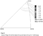
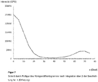
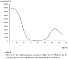
- Decisive in this case is the section through the ⁇ 111 ⁇ pole figure of the fcc-Ti 1-x Al x C y N z after integration of the intensities over the azimuth angle ⁇ (rotation angle around the sample surface normal).
- carbide indexable inserts of the geometry CNMA120412 with a composition of 86.5% by weight of WC, 5.5% by weight of Co, 2% by weight of TiC, 6% by weight (NbC + TaC ) and used with a mixed carbide-free edge zone.
- a Bernex BPX325S CVD coater with a reactor height of 1250 mm and a reactor diameter of 325 mm was used. The gas flow was radial to the longitudinal axis of the reactor.
- a first precursor gas mixture (VG1) with the starting compounds TiCl 4 and AlCl 3 and a second precursor gas mixture were prepared (VG2) with the starting compound NH 3 as a reactive nitrogen compound separated from each other into the reactor, so that a mixing of the two gas streams took place only when it enters the reaction zone.
- the volume gas flows of the precursor gas mixtures (VG1) and (VG2) were adjusted so that when preparing coatings according to the invention, the ratio of the volume gas flows v ⁇ (VG1) / v ⁇ (VG2) was less than 1.5.
- the parameters in the preparation of inventive Ti 1-x Al x C y N z coatings and comparative coatings are shown in Table 3.
- XRD X-ray diffraction
- EBSD electron diffraction methods
- ODF orientation density function
- Their representation in the form of an inverse pole figure shows the location and sharpness of any existing fiber texture.
- the Orientation Density function must either be constructed from a statistically sufficient number of single-orientation measurements (for EBSD) or calculated from measurements of a minimum number of pole figures at different reflections ⁇ hkl ⁇ (at XRD). See also: L. Sp dirt et al., Modern X-ray diffraction, 2nd edition, Vieweg & Teubner, 2009 ,
- X-ray diffraction measurements were taken on a GE Sensing & Inspection Technologies PTS3003 diffractometer using CuK ⁇ radiation.
- a parallel beam optic was used, which consisted on the primary side of a polycapillary and a 2 mm pinhole as a collimator.
- a parallel plate collimator with 0.4 ° divergence and a nickel K ⁇ filter was used.
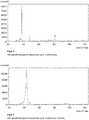
- Peak intensities and half-widths were determined from ⁇ -2 ⁇ measurements. After subtracting the background, pseudo-Voigt functions were fitted to the measured data, the K ⁇ 2 withdrawal taking place by means of K ⁇ 1 / K ⁇ 2 doublet adaptation. The values of the intensities and half-widths listed in Table 4 relate to the K ⁇ 1 -intefeions thus added.
- the lattice constants are calculated according to the Vergard law, assuming the lattice constants of TiN and AIN from the PDF maps 38-1420 and 46-1200, respectively.
- the ⁇ 101 ⁇ or ⁇ 202 ⁇ interferences of hexagonal AIN and the ⁇ 111 ⁇ or ⁇ 222 ⁇ reflections of cubic Ti 1-x Al x C y N z can vary more or less depending on the chemical composition overlap. Only the interference of the ⁇ 200 ⁇ plane of the cubic Ti 1-x Al x C y N z is by no further interference, such as B. by the substrate body or above or below arranged layers superimposed and has for random orientation the highest intensity.
- the measured intensity at 2 ⁇ ⁇ 38.1 ° is attributable primarily to the face-centered cubic Ti 1-x Al x C y N z phase or larger fractions of hexagonal AIN are included in the layer.
- Both X-ray diffraction measurements and EBSD measurements consistently show only very small proportions of hexagonal AIN phase in the layers according to the invention.
- the intensity distribution of all measured and recalculated pole pieces was approximately rotationally symmetric, i. the examined layers had fiber textures.
- pole figures were measured on the ⁇ 200 ⁇ and ⁇ 220 ⁇ reflections in addition to the ⁇ 111 ⁇ pole figure.
- the orientation density distribution function (ODF) was calculated using the LaboTex 3.0 software from LaboSoft, Poland, and the preferred orientation is shown as an inverse pole figure.
- ODF orientation density distribution function
- the intensity maximum was in the ⁇ 111> direction or ⁇ 10 ° angle deviation of ⁇ 111>.
- the ⁇ 222 ⁇ interference of the cubic face-centered Ti 1-x Al x C y N z layer was used and at 25 ⁇ angles from -60 ° to 60 ° (Increment 5 °).
- Residual stresses are usually expressed in units of megapascals (MPa), denoting residual stresses with a positive sign (+) and compressive residual stresses with a negative sign (-).
- EDX measurements were carried out on a Supra 40 VP scanning electron microscope from Carl Zeiss at 15 kV acceleration voltage with an INCA x-act EDX spectrometer from Oxford Instruments, UK.
- microhardness was measured according to DIN EN ISO 14577-1 and -4 using a universal hardness tester Fischerscope H100 from Helmut Fischer GmbH, Sindelfingen, Germany, on a cross-section of the coated body.
- the cemented carbide indexable inserts coated in the examples were subjected to compressed air dry blasting after CVD coating.
- the residual stresses in the Ti 1-x Al x C y N z layer and in the substrate (WC) were measured before and after the blast treatment.
- the beam parameters used and the measured residual stress values are given in Table 5.
- Precursor gas mixture VG1 [% by volume] Precursor gas mixture VG2 [% by volume] Ratio of volumetric gas flows v ⁇ (VG1) / v ⁇ (VG2) Thickness Ti 1-x Al x C y N z [ ⁇ m] H2 N 2 TiCl 4 AlCl 3 CH 3 CN H2 N2 NH 3 1 (Erf.) TiN 700 1 260 40.88 --- 0.08 0.32 0 36.56 21.2 0.96 0.7 12 2 (Erf.) TiN 700 1 260 54.35 --- 0.03 0.25 0 45,00 --- 0.37 1.2 6 3 (Erf.) TiN 700 1 260 53.33 --- 0.06 0.25 0 27,95 16.2 2.21 1.2 11 4 (Erf.) TiN 700 1.2 360 52.69 --- 0.02 0.16 0 46,90 --- 0.23 1.1 11 5 (Erf.) TiN 700 1.2 180 52.69 --- 0.02 0.
- Carbide indexable inserts of geometry CNMA120412 with a composition of 86.5 wt .-% WC, 5.5 wt .-% Co, 2 wt .-% TiC, 6 wt .-% (NbC + TaC) and with a mixed carbide-free edge zone were coated with the CVD coatings No. 1 and No. 8 shown in Table 3 and with the coating No. 9 described above (TiN / MT-Ti (C, N) / TiN).
- the total layer thickness was about 12 ⁇ m for all tools.
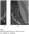
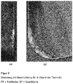
- the two reversible snowboards according to the prior art ( FIG. 1 : Coating 9; FIG. 2 : Coating 8) show extensive flaking of the layer along the cutting edge.
- FIG. 3 Coating 1
- hardly spalling is observed.
- Carbide indexable inserts of geometry SEHW1204AFN with a composition of 90.47 wt.% WC, 8 wt.% Co and 1.53 wt.% TaC / NbC were coated with the CVD coatings Nos. 4 and 3 given in Table 3 No. 8 coated.
- the total layer thickness was about 11 ⁇ m for all tools. Milling operations were carried out with the cutting inserts under the following cutting conditions: Workpiece material: Nodular cast iron GGG70 (strength 680 MPa)
- Working engagement: a e 98 mm
- u e 5 mm
- Carbide indexable inserts of geometry SEHW1204AFN with a composition of 90.47% by weight of WC, 8% by weight of Co and 1.53% by weight of TaC / NbC were coated with the CVD coating No. 5 as shown in Table 3 and coated with the coating No. 10 described above (TiN / MT-Ti (C, N)).
- Indexable inserts with Coating No. 5 were used on the one hand in an unirradiated state and on the other hand after a dry blasting treatment with ZrO 2 as a blasting medium in accordance with Sample S8 in Table 5. Milling operations were carried out with the cutting inserts under the following cutting conditions: Workpiece material: Gray cast iron GG25
- Working engagement: a e 98 mm
- u e 5 mm
- Carbide indexable inserts of geometry SEHW1204AFN with a composition of 90.47% by weight of WC, 8% by weight of Co and 1.53% by weight of TaC / NbC were coated with the CVD coating No. 5 as shown in Table 3 and coated with the coating No. 10 described above (TiN / MT-Ti (C, N)).
- 3 cutting inserts were tested. Milling operations were carried out with the cutting inserts under the following cutting conditions: Workpiece material: Mild steel St37 (strength approx. 500 MPa)
- Working engagement: a e 50 mm
- Got over: u e 350 mm
Claims (17)
- Procédé de fabrication d'un outil comportant un corps de base en métal dur, cermet, céramique, acier ou acier à coupe rapide, et un revêtement de protection contre l'usure, monocouche ou multicouche, appliqué dessus par le procédé CVD, le revêtement de protection contre l'usure présentant au moins une couche de Ti1-xAlxCyNz présentant des coefficients stoechiométriques 0,70 ≤ x < 1, 0 ≤ y < 0,25 et 0,75 ≤ z < 1,15, une épaisseur comprise dans la plage de 1 µm à 25 µm, procédé dans lequel, pour la fabrication de la couche de Ti1-xAlxCyNz,a) on place les corps à revêtir dans un réacteur CVD essentiellement cylindrique, qui est conçu pour insuffler les gaz de procédé sur le corps à revêtir dans une direction pour l'essentiel radiale par rapport à l'axe longitudinal du réacteur,b) on fournit deux mélanges de gaz précurseurs (VG1) et (VG2),
le premier mélange de gaz précurseurs (VG1) contenant0,005 % à 0,2 % en volume de TiCl4, 0,025 % à 0,5 % en volume d'AlCl3, eten tant que gaz support de l'hydrogène (H2) ou un mélange d'hydrogène et d'azote (H2/N2), etle deuxième mélange de gaz précurseurs (VG2) contenant0,1 à 3,0 % en volume d'au moins un donneur de N, choisi parmi l'ammoniac (NH3) et l'hydrazine (N2H4), eten tant que gaz support de l'hydrogène (H2) ou un mélange d'hydrogène et d'azote (H2/N2),et le premier mélange de gaz précurseurs (VG1) et/ou le deuxième mélange de gaz précurseurs (VG2) contenant éventuellement un donneur de C choisi parmi l'acétonitrile (CH3CN), l'éthane (C2H6), l'éthène (C2H4) et l'éthyne (C2H2) et des mélanges de ceux-ci, le pourcentage total en volume du donneur de N et du donneur de C dans les mélanges de gaz précurseurs (VG1, VG2) étant compris dans la plage de 0,1 à 3,0 % en volume,c) on maintient les deux mélanges de gaz précurseurs (VG1, VG2) séparés en amont de leur entrée dans la zone de réaction, et à une température de procédé dans le réacteur CVD comprise dans la plage de 600 °C à 850 °C et sous une pression de procédé dans le réacteur CVD comprise dans la plage de 0,2 à 18 kPa, on les introduit pour l'essentiel radialement par rapport à l'axe longitudinal du réacteur,le rapport entre les débits volumiques de gaz (V̇) des mélanges de gaz précurseurs (VG1, VG2) V̇ (VG1) / V̇ (VG2) étant inférieur à 1,5. - Procédé selon la revendication 1, caractérisé en ce que la température de procédé dans le réacteur CVD est comprise dans la plage de 650 °C à 800 °C, de préférence dans la plage de 675 °C à 750 °C, et/ou que la pression de procédé dans le réacteur CVD est comprise dans la plage de 0,2 à 7 kPa, de préférence dans la plage de 0,4 à 1,8 kPa.
- Procédé selon l'une des revendications précédentes, caractérisé en ce que le rapport entre les débits volumiques de gaz (V̇) des mélanges de gaz précurseurs (VGA, VG2), V̇ (VG1) / V̇ (VG2) est inférieur à 1,25, de préférence inférieur à 1,15.
- Procédé selon l'une des revendications précédentes, caractérisé en ce que la concentration du TiCl4 dans le mélange de gaz précurseurs (VG1) et la concentration du donneur de N dans le mélange de gaz précurseurs (VG2) sont ajustées de telle sorte que le rapport molaire de Ti à N dans les débits volumiques de gaz V̇ (VG1) et V̇ (VG2) introduits à l'étape c) dans le réacteur est ≤ 0,25.
- Procédé selon l'une des revendications précédentes, caractérisé en ce que le deuxième mélange de gaz précurseurs (VG2) contient ≤ 1,0 % en volume, de préférence ≤ 0,6 % en volume du donneur de N.
- Procédé selon l'une des revendications précédentes, caractérisé en ce que le donneur de N est l'ammoniac (NH3).
- Procédé selon l'une des revendications précédentes, caractérisé en ce que le revêtement de protection contre l'usure est soumis à un traitement par sablage à l'aide d'un agent de sablage particulier, de préférence le corindon, dans des conditions telles que la couche de Ti1-xAlxCyNz présente après le traitement de sablage des contraintes internes comprises dans la plage de +300 à -5000 MPa, de préférence dans la plage de -1 à -3500 MPa.
- Outil comportant un corps de base en métal dur, cermet, céramique, acier ou acier à coupe rapide et un revêtement de protection contre l'usure, monocouche ou multicouche, appliqué dessus par le procédé CVD, la couche de protection contre l'usure présentant au moins une couche de Ti1-xAlxCyNz ayant des coefficients stoechiométriques 0,70 ≤ x < 1, 0 ≤ y < 0,25 et 0,75 ≤ z < 1,15, caractérisé en ce que la couche de Ti1-xAlxCyNz présente une épaisseur comprise dans la plage de 1 µm à 25 µm et une orientation cristallographique préférentielle qui est caractérisée par un rapport entre les intensités des pics de diffraction des rayons X du plan cristallographique {111} et du plan {200}, pour lequel I{111}/I{200} > 1+h (ln h)2, h étant l'épaisseur de la couche de Ti1-xAlxCyNz, en « µm ».
- Outil selon la revendication 8, caractérisé en ce que la largeur à mi-hauteur (LMH) du pic de diffraction des rayons X du plan {111} de la couche de Ti1-xAlxCyNz est < 1°, de préférence < 0,6°, d'une manière particulièrement préférée < 0,45°.
- Outil selon l'une des revendications 8 ou 9, caractérisé en ce que la couche de Ti1-xAlxCyNz présente au moins 90 % en volume de phase Ti1-xAlxCyNz présentant une structure cubique à faces centrées (cfc), de préférence au moins 95 % en volume de phase Ti1-xAlxCyNz présentant une structure cubique à faces centrées (cfc), d'une manière particulièrement préférée au moins 98 % en volume de phase Ti1-xAlxCyNz présentant une structure cubique à faces centrées (cfc).
- Outil selon l'une des revendications 8 à 10, caractérisé en ce que la couche de Ti1-xAlxCyNz présente les coefficients stoechiométriques 0,70 ≤ x < 1, y = 0 et 0,95 ≤ z < 1,15.
- Outil selon l'une des revendications 8 à 11, caractérisé en ce que la couche de Ti1-xAlxCyNz présente une épaisseur comprise dans la plage de 3 µm à 20 µm, de préférence dans la plage de 4 à 15 µm.
- Outil selon l'une des revendications 8 à 12, caractérisé en ce que le rapport des intensités des pics de diffraction des rayons X du plan cristallographique {111} et du plan {200} de la couche de Ti1-xAlxCyNz est > 1+(h+3)(ln h)2.
- Outil selon l'une des revendications 8 à 13, caractérisé en ce que la couche de Ti1-xAlxCyNz présente une dureté Vickers (HV) > 2300 HV, de préférence > 2750 HV, d'une manière particulièrement préférée > 3000 HV.
- Outil selon l'une des revendications 8 à 14, caractérisé en ce que, entre le corps de base et la couche de Ti1-xAlxCyNz, est disposée au moins une couche d'un matériau dur, choisi parmi une couche de TiN, une couche de TiCN déposée par CVD à haute température (CVD) ou par CVD à température moyenne (MT-CVD), une couche d'Al2O3 et des combinaisons de celles-ci, et/ou en ce que, par-dessus la couche de Ti1-xAlxCyNz est disposée une couche de matériau dur supplémentaire, de préférence au moins une couche d'Al2O3 de la variété □ -Al2O3, □□-Al2O3 ou □-Al2O3, d'une manière particulièrement préférée une couche d'□-Al2O3, la couche d'Al2O3 étant déposée par CVD à haute température (CVD) ou par CVD à température moyenne (MT-CVD).
- Outil selon l'une des revendications 8 à 15, caractérisé en ce que le maximum absolu, mesuré par radiographie aux rayons X ou par EBSD, de l'intensité de diffraction des plans cristallographiques {111} de la couche de cfc-Ti1-xAlxCyNz se trouve à l'intérieur d'une plage angulaire α = ± 10°, de préférence à l'intérieur de la plage α = ± 5°, d'une manière particulièrement préférée dans la plage α = ± 1°, en partant de la direction normale de la surface de l'échantillon.
- Outil selon l'une des revendications 8 à 16, fabriqué selon l'une des revendications 1 à 16.
Applications Claiming Priority (2)
| Application Number | Priority Date | Filing Date | Title |
|---|---|---|---|
| DE102013104254.6A DE102013104254A1 (de) | 2013-04-26 | 2013-04-26 | Werkzeug mit CVD-Beschichtung |
| PCT/EP2014/057720 WO2014173755A1 (fr) | 2013-04-26 | 2014-04-16 | Outil revêtu par dépôt chimique en phase vapeur |
Publications (2)
| Publication Number | Publication Date |
|---|---|
| EP2989227A1 EP2989227A1 (fr) | 2016-03-02 |
| EP2989227B1 true EP2989227B1 (fr) | 2018-06-27 |
Family
ID=50543043
Family Applications (1)
| Application Number | Title | Priority Date | Filing Date |
|---|---|---|---|
| EP14718568.0A Active EP2989227B1 (fr) | 2013-04-26 | 2014-04-16 | Outil revêtu par dépôt chimique en phase vapeur |
Country Status (8)
| Country | Link |
|---|---|
| US (1) | US9976213B2 (fr) |
| EP (1) | EP2989227B1 (fr) |
| JP (1) | JP6542753B2 (fr) |
| KR (1) | KR102257864B1 (fr) |
| CN (1) | CN105247099B (fr) |
| DE (1) | DE102013104254A1 (fr) |
| ES (1) | ES2684410T3 (fr) |
| WO (1) | WO2014173755A1 (fr) |
Families Citing this family (15)
| Publication number | Priority date | Publication date | Assignee | Title |
|---|---|---|---|---|
| DE102014103220A1 (de) | 2014-03-11 | 2015-09-17 | Walter Ag | TiAIN-Schichten mit Lamellenstruktur |
| CN107771225B (zh) * | 2015-07-27 | 2020-10-30 | 瓦尔特公开股份有限公司 | 具有TiAlN涂层的刀具 |
| CN108884562A (zh) * | 2016-03-31 | 2018-11-23 | 瓦尔特公开股份有限公司 | 用H-ALN层和TI1-XAlXCYNZ层的涂覆的切削刀具 |
| JP6044861B1 (ja) * | 2016-04-08 | 2016-12-14 | 住友電工ハードメタル株式会社 | 表面被覆切削工具およびその製造方法 |
| JP6973699B2 (ja) * | 2016-04-14 | 2021-12-01 | 住友電工ハードメタル株式会社 | 表面被覆切削工具およびその製造方法 |
| JP6045010B1 (ja) * | 2016-04-14 | 2016-12-14 | 住友電工ハードメタル株式会社 | 表面被覆切削工具およびその製造方法 |
| EP3263738B1 (fr) * | 2016-07-01 | 2018-12-05 | Walter Ag | Outil de coupe avec une couche d'alumine texturée |
| US11015242B2 (en) * | 2016-07-07 | 2021-05-25 | Moldino Tool Engineering, Ltd. | Hard coating, hard-coated tool, and their production methods |
| US11020804B2 (en) * | 2017-02-28 | 2021-06-01 | Sumitomo Electric Hardmetal Corp. | Surface-coated cutting tool and method for manufacturing the same |
| KR102064172B1 (ko) * | 2017-09-01 | 2020-01-09 | 한국야금 주식회사 | 내마모성과 인성이 우수한 경질피막 |
| CN109975339B (zh) * | 2017-12-28 | 2023-08-15 | 厦门钨业股份有限公司 | 一种TiCN基金属陶瓷性能的评估方法 |
| JP2020104255A (ja) * | 2018-12-27 | 2020-07-09 | 三菱マテリアル株式会社 | 表面被覆切削工具 |
| CN116847938A (zh) * | 2021-02-12 | 2023-10-03 | 株式会社Moldino | 包覆工具 |
| CN114517283A (zh) * | 2022-01-24 | 2022-05-20 | 赣州澳克泰工具技术有限公司 | 沉积在基体表面的多层涂层系统及其制备方法 |
| US20240051033A1 (en) | 2022-08-10 | 2024-02-15 | Iscar, Ltd. | CUTTING TOOL WITH A TiAlN COATING HAVING RAKE AND RELIEF SURFACES WITH DIFFERENT RESIDUAL STRESSES |
Citations (3)
| Publication number | Priority date | Publication date | Assignee | Title |
|---|---|---|---|---|
| JP2007168032A (ja) * | 2005-12-22 | 2007-07-05 | Mitsubishi Materials Corp | 高速重切削条件で硬質被覆層がすぐれた耐摩耗性および耐チッピング性を発揮する表面被覆切削工具 |
| WO2008031768A1 (fr) | 2006-09-15 | 2008-03-20 | Sandvik Intellectual Property Ab | Outil de découpe revêtu |
| WO2012126030A1 (fr) | 2011-03-18 | 2012-09-27 | Boehlerit Gmbh & Co. Kg. | Corps pourvu d'un revêtement et son procédé de production |
Family Cites Families (25)
| Publication number | Priority date | Publication date | Assignee | Title |
|---|---|---|---|---|
| US5879823A (en) * | 1995-12-12 | 1999-03-09 | Kennametal Inc. | Coated cutting tool |
| FR2745299B1 (fr) * | 1996-02-27 | 1998-06-19 | Centre Nat Rech Scient | Procede de formation de revetements de ti1-xalxn |
| AU4028297A (en) * | 1997-09-12 | 1999-04-05 | Balzers Aktiengesellschaft | Tool having a protective layer system |
| JP3031907B2 (ja) * | 1998-03-16 | 2000-04-10 | 日立ツール株式会社 | 多層膜被覆部材 |
| SE521284C2 (sv) * | 1999-05-19 | 2003-10-21 | Sandvik Ab | Aluminiumoxidbelagt skärverktyg för metallbearbetning |
| US6572991B1 (en) | 2000-02-04 | 2003-06-03 | Seco Tools Ab | Deposition of γ-Al2O3 by means of CVD |
| JP2001341008A (ja) * | 2000-06-02 | 2001-12-11 | Hitachi Tool Engineering Ltd | 窒化チタンアルミニウム膜被覆工具及びその製造方法 |
| EP1698714B1 (fr) | 2000-12-28 | 2009-09-02 | Kabushiki Kaisha Kobe Seiko Sho | Cible pour l'obtention d'un film dur |
| EP1553210B1 (fr) * | 2002-08-08 | 2014-05-28 | Kabushiki Kaisha Kobe Seiko Sho | Procédé de fabrication d'un revetement à base d'alumine composé principalement d'une structure cristalline de type alpha |
| SE526526C3 (sv) | 2003-04-01 | 2005-10-26 | Sandvik Intellectual Property | Sätt att belägga skär med A1203 samt ett med A1203 belagt skärverktyg |
| SE529223C2 (sv) | 2005-05-06 | 2007-06-05 | Seco Tools Ab | Belagt skärverktyg innefattande hexagonal h-(Mel,Me2)Xfas |
| DE102005032860B4 (de) * | 2005-07-04 | 2007-08-09 | Fraunhofer-Gesellschaft zur Förderung der angewandten Forschung e.V. | Hartstoffbeschichtete Körper und Verfahren zu deren Herstellung |
| KR101307125B1 (ko) * | 2005-07-29 | 2013-09-10 | 스미또모 덴꼬오 하드메탈 가부시끼가이샤 | 날끝 교환형 절삭 팁 및 그 제조 방법 |
| US8080312B2 (en) * | 2006-06-22 | 2011-12-20 | Kennametal Inc. | CVD coating scheme including alumina and/or titanium-containing materials and method of making the same |
| SE531971C2 (sv) | 2007-08-24 | 2009-09-15 | Seco Tools Ab | Belagt skärverktyg för allmän svarvning i varmhållfast superlegeringar (HRSA) |
| SE531946C2 (sv) | 2007-08-24 | 2009-09-15 | Seco Tools Ab | Skär för fräsning i gjutjärn |
| DE102007000512B3 (de) | 2007-10-16 | 2009-01-29 | Fraunhofer-Gesellschaft zur Förderung der angewandten Forschung e.V. | Hartstoffbeschichtete Körper und Verfahren zu deren Herstellung |
| DE102008013966A1 (de) | 2008-03-12 | 2009-09-17 | Kennametal Inc. | Hartstoffbeschichteter Körper |
| DE102008013965A1 (de) | 2008-03-12 | 2009-09-17 | Kennametal Inc. | Hartstoffbeschichteter Körper |
| DE102008013964A1 (de) | 2008-03-12 | 2009-09-17 | Kennametal Inc. | Hartstoffbeschichteter Körper |
| DE102008019202A1 (de) | 2008-04-17 | 2009-10-22 | Kennametal Inc. | Beschichtungsverfahren , Werkstück oder Werkzeug und dessen Verwendung |
| DE102009046667B4 (de) * | 2009-11-12 | 2016-01-28 | Fraunhofer-Gesellschaft zur Förderung der angewandten Forschung e.V. | Beschichtete Körper aus Metall, Hartmetal, Cermet oder Keramik sowie Verfahren zur Beschichtung derartiger Körper |
| EP2643498B1 (fr) * | 2010-11-23 | 2018-10-10 | Seco Tools AB | Insert d'outils de coupe revetus pour machinage metallique qui produit des hautes temperatures |
| US8440328B2 (en) | 2011-03-18 | 2013-05-14 | Kennametal Inc. | Coating for improved wear resistance |
| EP2570511B1 (fr) | 2011-09-16 | 2019-03-20 | Walter AG | Outil de découpe revêtu d'alpha-alumine synthétique à joint de grain |
-
2013
- 2013-04-26 DE DE102013104254.6A patent/DE102013104254A1/de not_active Withdrawn
-
2014
- 2014-04-16 WO PCT/EP2014/057720 patent/WO2014173755A1/fr active Application Filing
- 2014-04-16 KR KR1020157031256A patent/KR102257864B1/ko active IP Right Grant
- 2014-04-16 JP JP2016509387A patent/JP6542753B2/ja active Active
- 2014-04-16 EP EP14718568.0A patent/EP2989227B1/fr active Active
- 2014-04-16 ES ES14718568.0T patent/ES2684410T3/es active Active
- 2014-04-16 US US14/781,622 patent/US9976213B2/en active Active
- 2014-04-16 CN CN201480022401.5A patent/CN105247099B/zh active Active
Patent Citations (3)
| Publication number | Priority date | Publication date | Assignee | Title |
|---|---|---|---|---|
| JP2007168032A (ja) * | 2005-12-22 | 2007-07-05 | Mitsubishi Materials Corp | 高速重切削条件で硬質被覆層がすぐれた耐摩耗性および耐チッピング性を発揮する表面被覆切削工具 |
| WO2008031768A1 (fr) | 2006-09-15 | 2008-03-20 | Sandvik Intellectual Property Ab | Outil de découpe revêtu |
| WO2012126030A1 (fr) | 2011-03-18 | 2012-09-27 | Boehlerit Gmbh & Co. Kg. | Corps pourvu d'un revêtement et son procédé de production |
Non-Patent Citations (7)
| Title |
|---|
| "Broschüre Ionbond Bernex CVD", IONBOND, March 2011 (2011-03-01), XP055578861 |
| "Fraunhofer ADVANCER Newsletter", FRAUNHOFER ADVANCER, March 2012 (2012-03-01), XP055578879 |
| "Prospekt TERAspeed", BOEHLERIT, September 2011 (2011-09-01), XP055578886 |
| "TeraSpeed - Renaissance für CVD-Verfahren", WERKZEUG MIT CVD-BESCHICHTUNG, March 2011 (2011-03-01), pages 130 - 133, XP055578860 |
| I. ENDLER ET AL.: "Aluminum-rich TiAlCN coatings by Low Pressure CVD", SURFACE AND COATINGS TECHNOLOGY, vol. 205, no. 5, 7 September 2010 (2010-09-07), pages 1307 - 1312, XP027507482 |
| I. ENDLER ET AL.: "Novel aluminum-rich TiI-xAlxN coatings by LPCVD", SURFACE & COATINGS TECHNOLOGY, vol. 203, no. 5-7, 15 May 2008 (2008-05-15), pages 530 - 533, XP002524222 |
| U. KRETSCHMANN ET AL.: "Over the top - Fräsen ohne Limit", WERKZEUG TEKNIK, vol. 119, April 2011 (2011-04-01), pages 54 - 56, XP055578890 |
Also Published As
| Publication number | Publication date |
|---|---|
| EP2989227A1 (fr) | 2016-03-02 |
| CN105247099A (zh) | 2016-01-13 |
| JP6542753B2 (ja) | 2019-07-10 |
| KR20160002867A (ko) | 2016-01-08 |
| KR102257864B1 (ko) | 2021-05-28 |
| WO2014173755A1 (fr) | 2014-10-30 |
| CN105247099B (zh) | 2019-01-11 |
| DE102013104254A1 (de) | 2014-10-30 |
| US20160053372A1 (en) | 2016-02-25 |
| US9976213B2 (en) | 2018-05-22 |
| ES2684410T3 (es) | 2018-10-02 |
| JP2016522323A (ja) | 2016-07-28 |
Similar Documents
| Publication | Publication Date | Title |
|---|---|---|
| EP2989227B1 (fr) | Outil revêtu par dépôt chimique en phase vapeur | |
| EP3117021B1 (fr) | Couches de tialcn ayant une structure lamellaire | |
| DE102009046667B4 (de) | Beschichtete Körper aus Metall, Hartmetal, Cermet oder Keramik sowie Verfahren zur Beschichtung derartiger Körper | |
| EP2756110B1 (fr) | Organe de coupe et son procédé de fabrication | |
| DE69509218T3 (de) | Oxidbeschichtetes schneidwerkzeug | |
| EP1902155B1 (fr) | Corps recouverts d'une substance dure, et leur procede de production | |
| EP0980445B1 (fr) | Outil rapporte d'usinage, et son procede de fabrication | |
| DE102008009487B4 (de) | Strahlbehandelter Schneideinsatz und Verfahren | |
| DE102012003857B4 (de) | Beschichtete Schneidwerkzeuge | |
| DE102015121206B4 (de) | Widerstandsfähige Nanoverbundbeschichtungen | |
| DE112011100870B4 (de) | Beschichteter keramischer Schneideeinsatz und Verfahren zur Herstellung desselben | |
| DE102019006845B4 (de) | Beschichtetes Schneidwerkzeug | |
| DE112011101379T5 (de) | Beschichtung für Schneidwerkzeuge | |
| WO1992017623A1 (fr) | Corps composite, son utilisation et son procede de production | |
| EP2962794A1 (fr) | Outil de coupe à revêtement de surface | |
| EP2209929A1 (fr) | Objet revêtu | |
| DE102021203039A1 (de) | Beschichtetes schneidwerkzeug | |
| DE102012002394B4 (de) | Beschichtete Substrate und Verfahren zu deren Herstellung | |
| WO2009034036A1 (fr) | Insert de coupe traité par jet de matière et procédé | |
| EP2486164B1 (fr) | Outil de coupe pour l'usinage des matériaux métalliques | |
| DE112019004436T5 (de) | Beschichtetes werkzeug und schneidwerkzeug | |
| DE112021005562T5 (de) | Beschichtetes werkzeug und schneidwerkzeug, welches das beschichtete werkzeug aufweist | |
| DE112021005580T5 (de) | Beschichtetes werkzeug und schneidwerkzeug, welches das beschichtete werkzeug aufweist |
Legal Events
| Date | Code | Title | Description |
|---|---|---|---|
| PUAI | Public reference made under article 153(3) epc to a published international application that has entered the european phase |
Free format text: ORIGINAL CODE: 0009012 |
|
| 17P | Request for examination filed |
Effective date: 20151016 |
|
| AK | Designated contracting states |
Kind code of ref document: A1 Designated state(s): AL AT BE BG CH CY CZ DE DK EE ES FI FR GB GR HR HU IE IS IT LI LT LU LV MC MK MT NL NO PL PT RO RS SE SI SK SM TR |
|
| AX | Request for extension of the european patent |
Extension state: BA ME |
|
| RIN1 | Information on inventor provided before grant (corrected) |
Inventor name: MANNS, THORSTEN Inventor name: RUPPI, SAKARI Inventor name: STIENS, DIRK |
|
| DAX | Request for extension of the european patent (deleted) | ||
| REG | Reference to a national code |
Ref country code: DE Ref legal event code: R079 Ref document number: 502014008661 Country of ref document: DE Free format text: PREVIOUS MAIN CLASS: C23C0016340000 Ipc: C23C0016455000 |
|
| GRAP | Despatch of communication of intention to grant a patent |
Free format text: ORIGINAL CODE: EPIDOSNIGR1 |
|
| STAA | Information on the status of an ep patent application or granted ep patent |
Free format text: STATUS: GRANT OF PATENT IS INTENDED |
|
| RIC1 | Information provided on ipc code assigned before grant |
Ipc: C23C 16/455 20060101AFI20180202BHEP Ipc: C23C 16/34 20060101ALI20180202BHEP |
|
| INTG | Intention to grant announced |
Effective date: 20180220 |
|
| RIN1 | Information on inventor provided before grant (corrected) |
Inventor name: MANNS, THORSTEN Inventor name: RUPPI, SAKARI Inventor name: STIENS, DIRK |
|
| GRAS | Grant fee paid |
Free format text: ORIGINAL CODE: EPIDOSNIGR3 |
|
| GRAA | (expected) grant |
Free format text: ORIGINAL CODE: 0009210 |
|
| STAA | Information on the status of an ep patent application or granted ep patent |
Free format text: STATUS: THE PATENT HAS BEEN GRANTED |
|
| AK | Designated contracting states |
Kind code of ref document: B1 Designated state(s): AL AT BE BG CH CY CZ DE DK EE ES FI FR GB GR HR HU IE IS IT LI LT LU LV MC MK MT NL NO PL PT RO RS SE SI SK SM TR |
|
| REG | Reference to a national code |
Ref country code: GB Ref legal event code: FG4D Free format text: NOT ENGLISH |
|
| REG | Reference to a national code |
Ref country code: AT Ref legal event code: REF Ref document number: 1012426 Country of ref document: AT Kind code of ref document: T Effective date: 20180715 |
|
| REG | Reference to a national code |
Ref country code: DE Ref legal event code: R096 Ref document number: 502014008661 Country of ref document: DE |
|
| REG | Reference to a national code |
Ref country code: IE Ref legal event code: FG4D Free format text: LANGUAGE OF EP DOCUMENT: GERMAN |
|
| REG | Reference to a national code |
Ref country code: ES Ref legal event code: FG2A Ref document number: 2684410 Country of ref document: ES Kind code of ref document: T3 Effective date: 20181002 |
|
| PG25 | Lapsed in a contracting state [announced via postgrant information from national office to epo] |
Ref country code: SE Free format text: LAPSE BECAUSE OF FAILURE TO SUBMIT A TRANSLATION OF THE DESCRIPTION OR TO PAY THE FEE WITHIN THE PRESCRIBED TIME-LIMIT Effective date: 20180627 Ref country code: BG Free format text: LAPSE BECAUSE OF FAILURE TO SUBMIT A TRANSLATION OF THE DESCRIPTION OR TO PAY THE FEE WITHIN THE PRESCRIBED TIME-LIMIT Effective date: 20180927 Ref country code: FI Free format text: LAPSE BECAUSE OF FAILURE TO SUBMIT A TRANSLATION OF THE DESCRIPTION OR TO PAY THE FEE WITHIN THE PRESCRIBED TIME-LIMIT Effective date: 20180627 Ref country code: NO Free format text: LAPSE BECAUSE OF FAILURE TO SUBMIT A TRANSLATION OF THE DESCRIPTION OR TO PAY THE FEE WITHIN THE PRESCRIBED TIME-LIMIT Effective date: 20180927 Ref country code: LT Free format text: LAPSE BECAUSE OF FAILURE TO SUBMIT A TRANSLATION OF THE DESCRIPTION OR TO PAY THE FEE WITHIN THE PRESCRIBED TIME-LIMIT Effective date: 20180627 |
|
| REG | Reference to a national code |
Ref country code: NL Ref legal event code: MP Effective date: 20180627 |
|
| REG | Reference to a national code |
Ref country code: LT Ref legal event code: MG4D |
|
| PG25 | Lapsed in a contracting state [announced via postgrant information from national office to epo] |
Ref country code: GR Free format text: LAPSE BECAUSE OF FAILURE TO SUBMIT A TRANSLATION OF THE DESCRIPTION OR TO PAY THE FEE WITHIN THE PRESCRIBED TIME-LIMIT Effective date: 20180928 Ref country code: HR Free format text: LAPSE BECAUSE OF FAILURE TO SUBMIT A TRANSLATION OF THE DESCRIPTION OR TO PAY THE FEE WITHIN THE PRESCRIBED TIME-LIMIT Effective date: 20180627 Ref country code: LV Free format text: LAPSE BECAUSE OF FAILURE TO SUBMIT A TRANSLATION OF THE DESCRIPTION OR TO PAY THE FEE WITHIN THE PRESCRIBED TIME-LIMIT Effective date: 20180627 Ref country code: RS Free format text: LAPSE BECAUSE OF FAILURE TO SUBMIT A TRANSLATION OF THE DESCRIPTION OR TO PAY THE FEE WITHIN THE PRESCRIBED TIME-LIMIT Effective date: 20180627 |
|
| PG25 | Lapsed in a contracting state [announced via postgrant information from national office to epo] |
Ref country code: NL Free format text: LAPSE BECAUSE OF FAILURE TO SUBMIT A TRANSLATION OF THE DESCRIPTION OR TO PAY THE FEE WITHIN THE PRESCRIBED TIME-LIMIT Effective date: 20180627 |
|
| PG25 | Lapsed in a contracting state [announced via postgrant information from national office to epo] |
Ref country code: RO Free format text: LAPSE BECAUSE OF FAILURE TO SUBMIT A TRANSLATION OF THE DESCRIPTION OR TO PAY THE FEE WITHIN THE PRESCRIBED TIME-LIMIT Effective date: 20180627 Ref country code: CZ Free format text: LAPSE BECAUSE OF FAILURE TO SUBMIT A TRANSLATION OF THE DESCRIPTION OR TO PAY THE FEE WITHIN THE PRESCRIBED TIME-LIMIT Effective date: 20180627 Ref country code: PL Free format text: LAPSE BECAUSE OF FAILURE TO SUBMIT A TRANSLATION OF THE DESCRIPTION OR TO PAY THE FEE WITHIN THE PRESCRIBED TIME-LIMIT Effective date: 20180627 Ref country code: EE Free format text: LAPSE BECAUSE OF FAILURE TO SUBMIT A TRANSLATION OF THE DESCRIPTION OR TO PAY THE FEE WITHIN THE PRESCRIBED TIME-LIMIT Effective date: 20180627 Ref country code: IS Free format text: LAPSE BECAUSE OF FAILURE TO SUBMIT A TRANSLATION OF THE DESCRIPTION OR TO PAY THE FEE WITHIN THE PRESCRIBED TIME-LIMIT Effective date: 20181027 Ref country code: SK Free format text: LAPSE BECAUSE OF FAILURE TO SUBMIT A TRANSLATION OF THE DESCRIPTION OR TO PAY THE FEE WITHIN THE PRESCRIBED TIME-LIMIT Effective date: 20180627 |
|
| PG25 | Lapsed in a contracting state [announced via postgrant information from national office to epo] |
Ref country code: SM Free format text: LAPSE BECAUSE OF FAILURE TO SUBMIT A TRANSLATION OF THE DESCRIPTION OR TO PAY THE FEE WITHIN THE PRESCRIBED TIME-LIMIT Effective date: 20180627 |
|
| REG | Reference to a national code |
Ref country code: DE Ref legal event code: R026 Ref document number: 502014008661 Country of ref document: DE |
|
| PLBI | Opposition filed |
Free format text: ORIGINAL CODE: 0009260 |
|
| PLAX | Notice of opposition and request to file observation + time limit sent |
Free format text: ORIGINAL CODE: EPIDOSNOBS2 |
|
| 26 | Opposition filed |
Opponent name: BOEHLERIT GMBH & CO. KG. Effective date: 20190327 |
|
| PG25 | Lapsed in a contracting state [announced via postgrant information from national office to epo] |
Ref country code: DK Free format text: LAPSE BECAUSE OF FAILURE TO SUBMIT A TRANSLATION OF THE DESCRIPTION OR TO PAY THE FEE WITHIN THE PRESCRIBED TIME-LIMIT Effective date: 20180627 |
|
| PLBB | Reply of patent proprietor to notice(s) of opposition received |
Free format text: ORIGINAL CODE: EPIDOSNOBS3 |
|
| PG25 | Lapsed in a contracting state [announced via postgrant information from national office to epo] |
Ref country code: SI Free format text: LAPSE BECAUSE OF FAILURE TO SUBMIT A TRANSLATION OF THE DESCRIPTION OR TO PAY THE FEE WITHIN THE PRESCRIBED TIME-LIMIT Effective date: 20180627 |
|
| PG25 | Lapsed in a contracting state [announced via postgrant information from national office to epo] |
Ref country code: AL Free format text: LAPSE BECAUSE OF FAILURE TO SUBMIT A TRANSLATION OF THE DESCRIPTION OR TO PAY THE FEE WITHIN THE PRESCRIBED TIME-LIMIT Effective date: 20180627 |
|
| REG | Reference to a national code |
Ref country code: BE Ref legal event code: MM Effective date: 20190430 |
|
| PG25 | Lapsed in a contracting state [announced via postgrant information from national office to epo] |
Ref country code: MC Free format text: LAPSE BECAUSE OF FAILURE TO SUBMIT A TRANSLATION OF THE DESCRIPTION OR TO PAY THE FEE WITHIN THE PRESCRIBED TIME-LIMIT Effective date: 20180627 Ref country code: LU Free format text: LAPSE BECAUSE OF NON-PAYMENT OF DUE FEES Effective date: 20190416 |
|
| PG25 | Lapsed in a contracting state [announced via postgrant information from national office to epo] |
Ref country code: BE Free format text: LAPSE BECAUSE OF NON-PAYMENT OF DUE FEES Effective date: 20190430 |
|
| PG25 | Lapsed in a contracting state [announced via postgrant information from national office to epo] |
Ref country code: TR Free format text: LAPSE BECAUSE OF FAILURE TO SUBMIT A TRANSLATION OF THE DESCRIPTION OR TO PAY THE FEE WITHIN THE PRESCRIBED TIME-LIMIT Effective date: 20180627 |
|
| PG25 | Lapsed in a contracting state [announced via postgrant information from national office to epo] |
Ref country code: IE Free format text: LAPSE BECAUSE OF NON-PAYMENT OF DUE FEES Effective date: 20190416 |
|
| PG25 | Lapsed in a contracting state [announced via postgrant information from national office to epo] |
Ref country code: PT Free format text: LAPSE BECAUSE OF FAILURE TO SUBMIT A TRANSLATION OF THE DESCRIPTION OR TO PAY THE FEE WITHIN THE PRESCRIBED TIME-LIMIT Effective date: 20181029 |
|
| REG | Reference to a national code |
Ref country code: DE Ref legal event code: R100 Ref document number: 502014008661 Country of ref document: DE |
|
| PLCK | Communication despatched that opposition was rejected |
Free format text: ORIGINAL CODE: EPIDOSNREJ1 |
|
| PLBN | Opposition rejected |
Free format text: ORIGINAL CODE: 0009273 |
|
| STAA | Information on the status of an ep patent application or granted ep patent |
Free format text: STATUS: OPPOSITION REJECTED |
|
| 27O | Opposition rejected |
Effective date: 20200911 |
|
| PG25 | Lapsed in a contracting state [announced via postgrant information from national office to epo] |
Ref country code: CY Free format text: LAPSE BECAUSE OF FAILURE TO SUBMIT A TRANSLATION OF THE DESCRIPTION OR TO PAY THE FEE WITHIN THE PRESCRIBED TIME-LIMIT Effective date: 20180627 |
|
| PG25 | Lapsed in a contracting state [announced via postgrant information from national office to epo] |
Ref country code: HU Free format text: LAPSE BECAUSE OF FAILURE TO SUBMIT A TRANSLATION OF THE DESCRIPTION OR TO PAY THE FEE WITHIN THE PRESCRIBED TIME-LIMIT; INVALID AB INITIO Effective date: 20140416 Ref country code: MT Free format text: LAPSE BECAUSE OF FAILURE TO SUBMIT A TRANSLATION OF THE DESCRIPTION OR TO PAY THE FEE WITHIN THE PRESCRIBED TIME-LIMIT Effective date: 20180627 |
|
| PGFP | Annual fee paid to national office [announced via postgrant information from national office to epo] |
Ref country code: CH Payment date: 20220314 Year of fee payment: 9 |
|
| PG25 | Lapsed in a contracting state [announced via postgrant information from national office to epo] |
Ref country code: MK Free format text: LAPSE BECAUSE OF FAILURE TO SUBMIT A TRANSLATION OF THE DESCRIPTION OR TO PAY THE FEE WITHIN THE PRESCRIBED TIME-LIMIT Effective date: 20180627 |
|
| PGFP | Annual fee paid to national office [announced via postgrant information from national office to epo] |
Ref country code: ES Payment date: 20220506 Year of fee payment: 9 |
|
| PGFP | Annual fee paid to national office [announced via postgrant information from national office to epo] |
Ref country code: AT Payment date: 20220325 Year of fee payment: 9 |
|
| PGFP | Annual fee paid to national office [announced via postgrant information from national office to epo] |
Ref country code: FR Payment date: 20230328 Year of fee payment: 10 |
|
| PGFP | Annual fee paid to national office [announced via postgrant information from national office to epo] |
Ref country code: IT Payment date: 20230310 Year of fee payment: 10 Ref country code: GB Payment date: 20230302 Year of fee payment: 10 |
|
| P01 | Opt-out of the competence of the unified patent court (upc) registered |
Effective date: 20230603 |
|
| PGFP | Annual fee paid to national office [announced via postgrant information from national office to epo] |
Ref country code: DE Payment date: 20230307 Year of fee payment: 10 |
|
| REG | Reference to a national code |
Ref country code: CH Ref legal event code: PL |
|
| REG | Reference to a national code |
Ref country code: AT Ref legal event code: MM01 Ref document number: 1012426 Country of ref document: AT Kind code of ref document: T Effective date: 20230416 |
|
| PG25 | Lapsed in a contracting state [announced via postgrant information from national office to epo] |
Ref country code: LI Free format text: LAPSE BECAUSE OF NON-PAYMENT OF DUE FEES Effective date: 20230430 Ref country code: CH Free format text: LAPSE BECAUSE OF NON-PAYMENT OF DUE FEES Effective date: 20230430 Ref country code: AT Free format text: LAPSE BECAUSE OF NON-PAYMENT OF DUE FEES Effective date: 20230416 |