EP2989227B1 - Tool having cvd coating - Google Patents
Tool having cvd coating Download PDFInfo
- Publication number
- EP2989227B1 EP2989227B1 EP14718568.0A EP14718568A EP2989227B1 EP 2989227 B1 EP2989227 B1 EP 2989227B1 EP 14718568 A EP14718568 A EP 14718568A EP 2989227 B1 EP2989227 B1 EP 2989227B1
- Authority
- EP
- European Patent Office
- Prior art keywords
- layer
- cvd
- range
- precursor gas
- vol
- Prior art date
- Legal status (The legal status is an assumption and is not a legal conclusion. Google has not performed a legal analysis and makes no representation as to the accuracy of the status listed.)
- Active
Links
- 238000000576 coating method Methods 0.000 title claims description 76
- 239000011248 coating agent Substances 0.000 title claims description 57
- 239000010410 layer Substances 0.000 claims description 105
- 239000007789 gas Substances 0.000 claims description 64
- 239000000203 mixture Substances 0.000 claims description 60
- 238000000034 method Methods 0.000 claims description 44
- 239000002243 precursor Substances 0.000 claims description 42
- 230000008569 process Effects 0.000 claims description 38
- ATJFFYVFTNAWJD-UHFFFAOYSA-N Tin Chemical compound [Sn] ATJFFYVFTNAWJD-UHFFFAOYSA-N 0.000 claims description 24
- QGZKDVFQNNGYKY-UHFFFAOYSA-N Ammonia Chemical compound N QGZKDVFQNNGYKY-UHFFFAOYSA-N 0.000 claims description 18
- 238000002441 X-ray diffraction Methods 0.000 claims description 16
- IJGRMHOSHXDMSA-UHFFFAOYSA-N Atomic nitrogen Chemical compound N#N IJGRMHOSHXDMSA-UHFFFAOYSA-N 0.000 claims description 14
- 238000005422 blasting Methods 0.000 claims description 14
- 239000000463 material Substances 0.000 claims description 14
- WEVYAHXRMPXWCK-UHFFFAOYSA-N Acetonitrile Chemical compound CC#N WEVYAHXRMPXWCK-UHFFFAOYSA-N 0.000 claims description 12
- 229910052593 corundum Inorganic materials 0.000 claims description 12
- 229910052757 nitrogen Inorganic materials 0.000 claims description 12
- OAKJQQAXSVQMHS-UHFFFAOYSA-N Hydrazine Chemical compound NN OAKJQQAXSVQMHS-UHFFFAOYSA-N 0.000 claims description 9
- UFHFLCQGNIYNRP-UHFFFAOYSA-N Hydrogen Chemical compound [H][H] UFHFLCQGNIYNRP-UHFFFAOYSA-N 0.000 claims description 8
- 229910000831 Steel Inorganic materials 0.000 claims description 8
- 239000010431 corundum Substances 0.000 claims description 8
- 229910052739 hydrogen Inorganic materials 0.000 claims description 8
- 239000001257 hydrogen Substances 0.000 claims description 8
- 238000004519 manufacturing process Methods 0.000 claims description 8
- 239000010959 steel Substances 0.000 claims description 8
- HSFWRNGVRCDJHI-UHFFFAOYSA-N Acetylene Chemical compound C#C HSFWRNGVRCDJHI-UHFFFAOYSA-N 0.000 claims description 7
- 229910021529 ammonia Inorganic materials 0.000 claims description 7
- 239000012159 carrier gas Substances 0.000 claims description 7
- 229910000997 High-speed steel Inorganic materials 0.000 claims description 6
- 239000000919 ceramic Substances 0.000 claims description 6
- 239000011195 cermet Substances 0.000 claims description 6
- 238000001887 electron backscatter diffraction Methods 0.000 claims description 5
- VSCWAEJMTAWNJL-UHFFFAOYSA-K aluminium trichloride Chemical compound Cl[Al](Cl)Cl VSCWAEJMTAWNJL-UHFFFAOYSA-K 0.000 claims description 4
- 239000003795 chemical substances by application Substances 0.000 claims description 4
- 150000002431 hydrogen Chemical class 0.000 claims description 4
- OTMSDBZUPAUEDD-UHFFFAOYSA-N Ethane Chemical compound CC OTMSDBZUPAUEDD-UHFFFAOYSA-N 0.000 claims description 3
- VGGSQFUCUMXWEO-UHFFFAOYSA-N Ethene Chemical compound C=C VGGSQFUCUMXWEO-UHFFFAOYSA-N 0.000 claims description 3
- 229910003074 TiCl4 Inorganic materials 0.000 claims description 3
- 239000002356 single layer Substances 0.000 claims description 3
- XJDNKRIXUMDJCW-UHFFFAOYSA-J titanium tetrachloride Chemical compound Cl[Ti](Cl)(Cl)Cl XJDNKRIXUMDJCW-UHFFFAOYSA-J 0.000 claims description 3
- 238000012986 modification Methods 0.000 claims description 2
- 230000004048 modification Effects 0.000 claims description 2
- PNEYBMLMFCGWSK-UHFFFAOYSA-N aluminium oxide Inorganic materials [O-2].[O-2].[O-2].[Al+3].[Al+3] PNEYBMLMFCGWSK-UHFFFAOYSA-N 0.000 claims 4
- 229910001845 yogo sapphire Inorganic materials 0.000 claims 4
- 229910000069 nitrogen hydride Inorganic materials 0.000 claims 2
- 229910052594 sapphire Inorganic materials 0.000 claims 2
- 229910003158 γ-Al2O3 Inorganic materials 0.000 claims 1
- 238000005229 chemical vapour deposition Methods 0.000 description 38
- 238000005520 cutting process Methods 0.000 description 32
- 230000035882 stress Effects 0.000 description 22
- 239000013078 crystal Substances 0.000 description 13
- 238000005259 measurement Methods 0.000 description 13
- 238000003801 milling Methods 0.000 description 11
- 229910018072 Al 2 O 3 Inorganic materials 0.000 description 10
- 229910052751 metal Inorganic materials 0.000 description 10
- 239000002184 metal Substances 0.000 description 10
- 239000000835 fiber Substances 0.000 description 8
- 239000000758 substrate Substances 0.000 description 8
- 238000000151 deposition Methods 0.000 description 6
- 230000008021 deposition Effects 0.000 description 6
- 238000002149 energy-dispersive X-ray emission spectroscopy Methods 0.000 description 6
- 238000002360 preparation method Methods 0.000 description 6
- 239000002245 particle Substances 0.000 description 5
- 238000005240 physical vapour deposition Methods 0.000 description 5
- 230000000052 comparative effect Effects 0.000 description 4
- 238000003754 machining Methods 0.000 description 4
- 238000012360 testing method Methods 0.000 description 4
- 238000007514 turning Methods 0.000 description 4
- 229910052782 aluminium Inorganic materials 0.000 description 3
- 238000002474 experimental method Methods 0.000 description 3
- 230000010354 integration Effects 0.000 description 3
- 230000001360 synchronised effect Effects 0.000 description 3
- 229910001060 Gray iron Inorganic materials 0.000 description 2
- PXHVJJICTQNCMI-UHFFFAOYSA-N Nickel Chemical compound [Ni] PXHVJJICTQNCMI-UHFFFAOYSA-N 0.000 description 2
- 229910010037 TiAlN Inorganic materials 0.000 description 2
- 238000004458 analytical method Methods 0.000 description 2
- 238000013459 approach Methods 0.000 description 2
- 230000008901 benefit Effects 0.000 description 2
- 239000000460 chlorine Substances 0.000 description 2
- 150000001805 chlorine compounds Chemical class 0.000 description 2
- 238000009826 distribution Methods 0.000 description 2
- 150000002739 metals Chemical class 0.000 description 2
- 238000005555 metalworking Methods 0.000 description 2
- 230000002441 reversible effect Effects 0.000 description 2
- 239000007858 starting material Substances 0.000 description 2
- ZAMOUSCENKQFHK-UHFFFAOYSA-N Chlorine atom Chemical compound [Cl] ZAMOUSCENKQFHK-UHFFFAOYSA-N 0.000 description 1
- 229910001141 Ductile iron Inorganic materials 0.000 description 1
- 241000976924 Inca Species 0.000 description 1
- 229910001209 Low-carbon steel Inorganic materials 0.000 description 1
- 238000005299 abrasion Methods 0.000 description 1
- 230000001133 acceleration Effects 0.000 description 1
- 230000006978 adaptation Effects 0.000 description 1
- XAGFODPZIPBFFR-UHFFFAOYSA-N aluminium Chemical compound [Al] XAGFODPZIPBFFR-UHFFFAOYSA-N 0.000 description 1
- 230000015572 biosynthetic process Effects 0.000 description 1
- 238000004364 calculation method Methods 0.000 description 1
- 230000008859 change Effects 0.000 description 1
- 229910052801 chlorine Inorganic materials 0.000 description 1
- 230000009918 complex formation Effects 0.000 description 1
- 239000002826 coolant Substances 0.000 description 1
- 238000001816 cooling Methods 0.000 description 1
- 238000012937 correction Methods 0.000 description 1
- 230000007423 decrease Effects 0.000 description 1
- 238000005315 distribution function Methods 0.000 description 1
- 230000000694 effects Effects 0.000 description 1
- 238000002003 electron diffraction Methods 0.000 description 1
- 239000000839 emulsion Substances 0.000 description 1
- 238000005516 engineering process Methods 0.000 description 1
- 239000012530 fluid Substances 0.000 description 1
- 230000004941 influx Effects 0.000 description 1
- 238000007689 inspection Methods 0.000 description 1
- 238000002156 mixing Methods 0.000 description 1
- 229910052759 nickel Inorganic materials 0.000 description 1
- 229910017464 nitrogen compound Inorganic materials 0.000 description 1
- 150000002830 nitrogen compounds Chemical class 0.000 description 1
- TWNQGVIAIRXVLR-UHFFFAOYSA-N oxo(oxoalumanyloxy)alumane Chemical compound O=[Al]O[Al]=O TWNQGVIAIRXVLR-UHFFFAOYSA-N 0.000 description 1
- 238000000623 plasma-assisted chemical vapour deposition Methods 0.000 description 1
- 230000010287 polarization Effects 0.000 description 1
- 238000000984 pole figure measurement Methods 0.000 description 1
- 238000012545 processing Methods 0.000 description 1
- 230000005855 radiation Effects 0.000 description 1
- 230000011514 reflex Effects 0.000 description 1
- 238000000926 separation method Methods 0.000 description 1
- 238000004901 spalling Methods 0.000 description 1
- 239000000126 substance Substances 0.000 description 1
- 230000008646 thermal stress Effects 0.000 description 1
- 230000000930 thermomechanical effect Effects 0.000 description 1
- 230000009466 transformation Effects 0.000 description 1
- 238000000844 transformation Methods 0.000 description 1
- 238000002424 x-ray crystallography Methods 0.000 description 1
Images

Classifications
-
- C—CHEMISTRY; METALLURGY
- C23—COATING METALLIC MATERIAL; COATING MATERIAL WITH METALLIC MATERIAL; CHEMICAL SURFACE TREATMENT; DIFFUSION TREATMENT OF METALLIC MATERIAL; COATING BY VACUUM EVAPORATION, BY SPUTTERING, BY ION IMPLANTATION OR BY CHEMICAL VAPOUR DEPOSITION, IN GENERAL; INHIBITING CORROSION OF METALLIC MATERIAL OR INCRUSTATION IN GENERAL
- C23C—COATING METALLIC MATERIAL; COATING MATERIAL WITH METALLIC MATERIAL; SURFACE TREATMENT OF METALLIC MATERIAL BY DIFFUSION INTO THE SURFACE, BY CHEMICAL CONVERSION OR SUBSTITUTION; COATING BY VACUUM EVAPORATION, BY SPUTTERING, BY ION IMPLANTATION OR BY CHEMICAL VAPOUR DEPOSITION, IN GENERAL
- C23C16/00—Chemical coating by decomposition of gaseous compounds, without leaving reaction products of surface material in the coating, i.e. chemical vapour deposition [CVD] processes
- C23C16/22—Chemical coating by decomposition of gaseous compounds, without leaving reaction products of surface material in the coating, i.e. chemical vapour deposition [CVD] processes characterised by the deposition of inorganic material, other than metallic material
- C23C16/30—Deposition of compounds, mixtures or solid solutions, e.g. borides, carbides, nitrides
- C23C16/34—Nitrides
-
- C—CHEMISTRY; METALLURGY
- C23—COATING METALLIC MATERIAL; COATING MATERIAL WITH METALLIC MATERIAL; CHEMICAL SURFACE TREATMENT; DIFFUSION TREATMENT OF METALLIC MATERIAL; COATING BY VACUUM EVAPORATION, BY SPUTTERING, BY ION IMPLANTATION OR BY CHEMICAL VAPOUR DEPOSITION, IN GENERAL; INHIBITING CORROSION OF METALLIC MATERIAL OR INCRUSTATION IN GENERAL
- C23C—COATING METALLIC MATERIAL; COATING MATERIAL WITH METALLIC MATERIAL; SURFACE TREATMENT OF METALLIC MATERIAL BY DIFFUSION INTO THE SURFACE, BY CHEMICAL CONVERSION OR SUBSTITUTION; COATING BY VACUUM EVAPORATION, BY SPUTTERING, BY ION IMPLANTATION OR BY CHEMICAL VAPOUR DEPOSITION, IN GENERAL
- C23C16/00—Chemical coating by decomposition of gaseous compounds, without leaving reaction products of surface material in the coating, i.e. chemical vapour deposition [CVD] processes
- C23C16/44—Chemical coating by decomposition of gaseous compounds, without leaving reaction products of surface material in the coating, i.e. chemical vapour deposition [CVD] processes characterised by the method of coating
- C23C16/455—Chemical coating by decomposition of gaseous compounds, without leaving reaction products of surface material in the coating, i.e. chemical vapour deposition [CVD] processes characterised by the method of coating characterised by the method used for introducing gases into reaction chamber or for modifying gas flows in reaction chamber
- C23C16/45502—Flow conditions in reaction chamber
- C23C16/45508—Radial flow
Definitions
- the invention relates to a tool having a base body made of hard metal, cermet, ceramic, steel or high-speed steel and a single or multi-layer wear protection coating applied thereon in the CVD method, wherein the wear protection coating has at least one Ti 1-x Al x C y N z layer with stoichiometry coefficients 0.70 ⁇ x ⁇ 1, 0 ⁇ y ⁇ 0.25 and 0.75 ⁇ z ⁇ 1.15 and having a crystallographic preferential orientation. Furthermore, the invention relates to a method for producing such a tool.
- Cutting inserts for material processing consist of a substrate body made of hard metal, cermet, ceramic, steel or high-speed steel, which is provided in most cases to improve the cutting and / or wear properties with a single or multi-layer hard coating.
- the hard material coating consists of superimposed layers of monometallic or mixed metallic hard material phases. Examples of monometallic hard material phases are TiN, TiC, TiCN and Al 2 O 3 . Examples of mixed metallic phases in which one metal is partially replaced by another in one crystal are TiAIN and TiAICN. Coatings of the aforementioned type are applied by CVD (chemical vapor deposition), PCVD (plasma assisted CVD) or PVD (physical vapor deposition).
- certain preferred orientations of the crystal growth in the deposition in the PVD or CVD process can have particular advantages, wherein for different applications of the cutting insert also different preferred orientations of certain layers of a coating can be particularly advantageous.
- the preference orientation of growth is usually in relation to the levels defined above the Miller indices of the crystal lattice and referred to as a crystallographic texture (eg, fiber texture).
- the DE 10 2005 032 860 discloses a hard coating having a face-centered cubic Ti 1-x Al x N layer with an Al content of 0.75 ⁇ x ⁇ 0.93 and a method of making the same.
- the DE 10 2007 000 512 discloses a hard coating with a layer of TiAIN deposited on a first layer of TiN, TiCN or TiC deposited directly on the substrate and a phase gradient bonding layer provided between the two layers.
- the TiAIN layer has a preferential orientation of crystal growth relative to the (200) plane of the crystal lattice.
- WO 2009/112115 disclose CVD-deposited TiAIN and TiAlCN layers with high Al content and cubic face-centered lattice, but no crystallographic preferential orientations of crystal growth are described.
- I. Endler et al. Describe in Surface & Coatings Technologhy 205 (210) 1307-1312 CVD method for aluminum-rich TiAlCN coatings, which have a preferred orientation of ⁇ 111 ⁇ and ⁇ 200 ⁇ planes.
- TiAIN coatings with various crystalline crystallographic preferences of crystal growth produced by PVD processes are known, however, in contrast to CVD coatings, PVD coatings with cubic face-centered lattice of the TiAIN coatings are limited to Al contents of less than 67%.
- TiAIN coatings with a crystallographic preferential orientation of the ⁇ 200 ⁇ plane with respect to the growth direction of the crystallites are described as being advantageous for metalworking (eg. US 2009/0274899 . US 2009/0074521 and WO 2009/127344 ).
- the object of the present invention was to provide cutting inserts for metal cutting, in particular the turning and milling of steel or cast materials, which have a comparison with the prior art improved wear resistance.
- percentages by volume in the precursor gas mixtures relate to the total volume of the gas mixture introduced into the reaction zone from the first and second precursor gas mixtures.
- the process of the invention Ti 1-x Al x C y N z - and Ti 1-x Al x N z layers with stoichiometric 0.70 ⁇ x ⁇ 1, 0 ⁇ y ⁇ 0.25 and 0.75 ⁇ z ⁇ 1.15 and can be made with face-centered cubic lattice having a pronounced orientation of crystal growth relative to the ⁇ 111 ⁇ plane of the crystal lattice.
- the coatings according to the invention have outstanding properties in metalworking. It has further been surprisingly found that in a cutting insert having a coating of the type described herein in metal cutting operations, particularly in turning and milling of steel or cast materials, improved wear resistance over a known cutting insert and a wider range of applications can be achieved.
- the CVD process of the present invention provides two precursor gas mixtures (VG1) and (VG2) wherein the first precursor gas mixture (VG1) contains the metals Ti and Al in the form of their chlorides and carrier gas and the second precursor gas mixture (VG2) contains at least one N-donor contains.
- the first precursor gas mixture (VG1) contains the metals Ti and Al in the form of their chlorides and carrier gas
- the second precursor gas mixture (VG2) contains at least one N-donor contains.
- N-donor ammonia (NH 3 ) or hydrazine (N 2 H 4 ) is used for the preparation TiAlCN layer
- N-donor and C-donor are used, for example, ammonia (NH 3 ) in admixture with ethene (C 2 H 4 ).
- Acetonitrile acts predominantly as a C donor in the process according to the invention and is therefore used in admixture with an N donor.
- N donor be supplied separately from the chlorides of the metals Ti and Al, while the C donor may be supplied via both the first precursor gas mixture (VG1) and the second precursor gas mixture (VG2).
- the N-donor is ammonia (NH 3 ).
- the inventively used CVD process is an MT-CVD process at a process temperature in the CVD reactor in the range of 600 ° C to 850 ° C and a process pressure in the range of 0.2 to 18 kPa.
- the CVD reactor is a substantially cylindrical reactor designed to flow the bodies to be coated with the process gases in a direction substantially radial to the longitudinal axis of the reactor, ie from the central axis of the cylindrical body Reactor in the direction of the outer wall of the reactor formed by the cylinder jacket.
- Such cylindrical reactors are known and commercially available, for example the Bernex® BPXpro CVD coating systems from lonbond AG Olten, Switzerland.
- An essential method of the process of the invention is that the two precursor gas mixtures (VG1) and (VG2) are kept separate prior to entering the reaction zone. If this is not done, the precursor gas streams may already react too early, for example in the supply lines, and the desired coating will not be achieved.
- Another essential method of the method according to the invention is that the ratio of the volume gas flows ( v ⁇ ) of the precursor gas mixtures (VG1, VG2) v ⁇ (VG1) / v ⁇ (VG2) is less than 1.5. If one selects the ratio of the volume gas flows ( v ⁇ ) of the precursor gas mixtures (VG1, VG2) v ⁇ (VG1) / v ⁇ (VG2) greater than 1.5, one does not obtain the desired properties of the Ti 1-x Al x C y N z layer in particular not the preferential orientation of crystal growth with respect to the ⁇ 111 ⁇ plane of the crystal lattice defined herein as the ratio of the intensities of the X-ray diffraction peaks I ⁇ 111 ⁇ / I ⁇ 200 ⁇ and according to the invention should be> 1+ h (In h) 2 where h is the thickness of the Ti 1-x Al x C y N z layer in " ⁇ m".
- the process temperature in the CVD reactor is in the range of 650 ° C to 800 ° C, preferably in the range of 675 ° C to 750 ° C.
- the process temperature in the CVD reactor is too low, the deposition rate may drop to an uneconomic level.
- layers with chlorine contents> 1 at.% And lower hardness are obtained at low temperatures.
- the process pressure in the CVD reactor is in the range from 0.2 to 7 kPa, preferably in the range from 0.4 to 1.8 kPa.
- the ratio of the volume gas flows ( v ⁇ ) of the precursor gas mixtures (VG1, VG2) v ⁇ (VG1) / v ⁇ (VG2) is less than 1.25, preferably less than 1.15.
- the concentration of TiCl 4 in the precursor gas mixture (VG1) and the concentration of nitrogen donor in the precursor gas mixture (VG2) are adjusted so that the molar ratio of Ti to N in the in step c) in the volume of the gas introduced by the reactor is v ⁇ (VG1) and v ⁇ (VG2) ⁇ 0.25.
- the volumetric gas streams v ⁇ (VG1) and v ⁇ (VG2) introduced into the reactor are given very Ti-rich layers, in particular when ammonia (NH 3 ) is used as N 2. donor. It is believed that if the ratio of Ti to N in the bulk gas streams is too high, the reaction of AlCl 3 is suppressed due to complex formation between TiCl 4 and the N donor.
- the second precursor gas mixture (VG2) contains ⁇ 1.0 vol .-%, preferably ⁇ 0.6 vol .-% of the N-donor.
- the concentration of the N-donor, optionally in admixture with C donor, in the second precursor gas mixture (VG2) is too high, the desired composition and crystallographic preferential orientation will not be obtained.
- the wear protection coating is subjected to a blasting treatment with a particulate blasting agent, preferably corundum, under conditions such that the Ti 1-x Al x C y N z layer after the blasting treatment has residual stresses in the range from +300 to -5000 MPa, preferably in the range of -1 to -3500 MPa.
- a particulate blasting agent preferably corundum
- the coating may flake off at the edges of the tool.
- the blast treatment is conveniently carried out at a fluid jet pressure of 1 bar to 10 bar.
- the duration of the jet treatment required for introducing the residual stresses according to the invention and the required jet pressure are parameters which the person skilled in the art can determine by simple experiments within the limits defined herein. A blanket statement is not possible here, since the self-adjusting residual stresses depend not only on the duration of the blast treatment and the jet pressure, but also on the structure and the thickness of the overall coating. However, the jet pressure has the much greater influence on the change in the residual stresses in the coating and the substrate body compared to the jet duration. Suitable jet treatment times are usually in the range of 10 to 600 seconds.
- the beam angle, d. H. the angle between the treatment beam and the surface of the tool also has a significant influence on the introduction of residual stresses. At a beam angle of 90 °, the maximum entry of compressive residual stresses occurs. Lower beam angles, d. H. oblique irradiation of the blasting abrasive, lead to a stronger abrasion of the surface and lower pressure self-tension entry.
- the invention also encompasses a tool having a base body made of cemented carbide, cermet, ceramic, steel or high-speed steel and a single-layer or multi-layer wear protection coating applied thereto by the CVD method, wherein the wear protection coating has at least one Ti 1-x Al x C y N z layer having stoichiometry coefficients 0.70 ⁇ x ⁇ 1, 0 ⁇ y ⁇ 0.25 and 0.75 ⁇ z ⁇ 1.15, characterized in that the Ti 1-x Al x C y N z layer has a thickness in the range of 1 ⁇ m to 25 ⁇ m and has a crystallographic preferential orientation characterized by a ratio of the intensities of the X-ray diffraction peaks of the ⁇ 111 ⁇ crystallographic plane and ⁇ 200 ⁇ Is characterized in that I ⁇ 111 ⁇ / I ⁇ 200 ⁇ > 1 + h (In h) 2 , where h is the thickness of the Ti 1-x Al x C y N z layer in "
- the half-width (FWHM) of the X-ray diffraction peak of the ⁇ 111 ⁇ plane of the Ti 1-x Al x C y N z layer is ⁇ 1 °, preferably ⁇ 0.6 °, particularly preferably ⁇ 0.45 °.
- Too high a full width at half maximum (FWHM) of the X-ray diffraction peak of the ⁇ 111 ⁇ plane of the Ti 1-x Al x C y N z layer indicates smaller grain sizes of the cubic face centered (fcc) phase or even portions of amorphous phases. This has proven in the previous tests as a disadvantage for the wear resistance.
- the Ti 1-x Al x C y N z layer has at least 90 vol.% Ti 1-x Al x C y N z phase with cubic face-centered (fcc) grating, preferably at least 95 Vol .-% Ti 1-x Al x C y N z phase with cubic face centered (fcc) lattice, more preferably at least 98 vol% Ti 1-x Al x C y N z phase with face-centered cubic (fcc) Grid on.
- the Ti 1-x Al x C y N z layer has a thickness in the range from 3 ⁇ m to 20 ⁇ m, preferably in the range from 4 to 15 ⁇ m.
- the layer may flake off due to the internal thermal stresses after the coating.
- the ratio of the intensities of the X-ray diffraction peaks of the ⁇ 111 ⁇ crystallographic plane and the (200) plane of the Ti 1-x Al x C y N z layer is> 1+ (h + 3) x (In h) 2 .
- the Ti 1-x Al x C y N z layer has a Vickers hardness (HV)> 2300 HV, preferably> 2750 HV, particularly preferably> 3000 HV.
- At least one further layer of hard material is arranged between the base body and the Ti 1-x Al x C y N z layer, selected from among a TiN layer, one by means of high-temperature CVD (CVD) or medium-temperature CVD (MT-CVD) deposited TiCN layer, an Al 2 O 3 layer and combinations thereof. It is particularly preferable to apply the further layers in the same temperature range, ie by medium-temperature CVD (MT-CVD), as the Ti 1-x Al x C y N z layer in order to avoid uneconomical cooling times.
- CVD high-temperature CVD
- MT-CVD medium-temperature CVD
- At least one further layer of hard material is arranged above the Ti 1 -x Al x C y N z layer, preferably at least one Al 2 O 3 layer of the modification ⁇ -Al 2 O 3 , ⁇ -Al 2 O 3 or ⁇ -Al 2 O 3 , wherein the Al 2 O 3 layer is deposited by means of high-temperature CVD (CVD) or medium-temperature CVD (MT-CVD).
- CVD high-temperature CVD
- MT-CVD medium-temperature CVD
- the aluminum oxide layer in the same temperature range, ie by medium-temperature CVD (MT-CVD) as the Ti 1-x Al x C y N z layer, in order to allow possible phase transformations of the Ti 1-x Al x C y N z layer to avoid.
- MT-CVD medium-temperature CVD
- Processes for the preparation of ⁇ -Al 2 O 3 , ⁇ -Al 2 O 3 or ⁇ -Al 2 O 3 layers in the range from 600 to 850 ° C. are known to the person skilled in the art, for example from EP 1 122 334 and EP 1 464 727 ,
- Decisive in this case is the section through the ⁇ 111 ⁇ pole figure of the fcc-Ti 1-x Al x C y N z after integration of the intensities over the azimuth angle ⁇ (rotation angle around the sample surface normal).
- carbide indexable inserts of the geometry CNMA120412 with a composition of 86.5% by weight of WC, 5.5% by weight of Co, 2% by weight of TiC, 6% by weight (NbC + TaC ) and used with a mixed carbide-free edge zone.
- a Bernex BPX325S CVD coater with a reactor height of 1250 mm and a reactor diameter of 325 mm was used. The gas flow was radial to the longitudinal axis of the reactor.
- a first precursor gas mixture (VG1) with the starting compounds TiCl 4 and AlCl 3 and a second precursor gas mixture were prepared (VG2) with the starting compound NH 3 as a reactive nitrogen compound separated from each other into the reactor, so that a mixing of the two gas streams took place only when it enters the reaction zone.
- the volume gas flows of the precursor gas mixtures (VG1) and (VG2) were adjusted so that when preparing coatings according to the invention, the ratio of the volume gas flows v ⁇ (VG1) / v ⁇ (VG2) was less than 1.5.
- the parameters in the preparation of inventive Ti 1-x Al x C y N z coatings and comparative coatings are shown in Table 3.
- XRD X-ray diffraction
- EBSD electron diffraction methods
- ODF orientation density function
- Their representation in the form of an inverse pole figure shows the location and sharpness of any existing fiber texture.
- the Orientation Density function must either be constructed from a statistically sufficient number of single-orientation measurements (for EBSD) or calculated from measurements of a minimum number of pole figures at different reflections ⁇ hkl ⁇ (at XRD). See also: L. Sp dirt et al., Modern X-ray diffraction, 2nd edition, Vieweg & Teubner, 2009 ,
- X-ray diffraction measurements were taken on a GE Sensing & Inspection Technologies PTS3003 diffractometer using CuK ⁇ radiation.
- a parallel beam optic was used, which consisted on the primary side of a polycapillary and a 2 mm pinhole as a collimator.
- a parallel plate collimator with 0.4 ° divergence and a nickel K ⁇ filter was used.
- Peak intensities and half-widths were determined from ⁇ -2 ⁇ measurements. After subtracting the background, pseudo-Voigt functions were fitted to the measured data, the K ⁇ 2 withdrawal taking place by means of K ⁇ 1 / K ⁇ 2 doublet adaptation. The values of the intensities and half-widths listed in Table 4 relate to the K ⁇ 1 -intefeions thus added.
- the lattice constants are calculated according to the Vergard law, assuming the lattice constants of TiN and AIN from the PDF maps 38-1420 and 46-1200, respectively.
- the ⁇ 101 ⁇ or ⁇ 202 ⁇ interferences of hexagonal AIN and the ⁇ 111 ⁇ or ⁇ 222 ⁇ reflections of cubic Ti 1-x Al x C y N z can vary more or less depending on the chemical composition overlap. Only the interference of the ⁇ 200 ⁇ plane of the cubic Ti 1-x Al x C y N z is by no further interference, such as B. by the substrate body or above or below arranged layers superimposed and has for random orientation the highest intensity.
- the measured intensity at 2 ⁇ ⁇ 38.1 ° is attributable primarily to the face-centered cubic Ti 1-x Al x C y N z phase or larger fractions of hexagonal AIN are included in the layer.
- Both X-ray diffraction measurements and EBSD measurements consistently show only very small proportions of hexagonal AIN phase in the layers according to the invention.
- the intensity distribution of all measured and recalculated pole pieces was approximately rotationally symmetric, i. the examined layers had fiber textures.
- pole figures were measured on the ⁇ 200 ⁇ and ⁇ 220 ⁇ reflections in addition to the ⁇ 111 ⁇ pole figure.
- the orientation density distribution function (ODF) was calculated using the LaboTex 3.0 software from LaboSoft, Poland, and the preferred orientation is shown as an inverse pole figure.
- ODF orientation density distribution function
- the intensity maximum was in the ⁇ 111> direction or ⁇ 10 ° angle deviation of ⁇ 111>.
- the ⁇ 222 ⁇ interference of the cubic face-centered Ti 1-x Al x C y N z layer was used and at 25 ⁇ angles from -60 ° to 60 ° (Increment 5 °).
- Residual stresses are usually expressed in units of megapascals (MPa), denoting residual stresses with a positive sign (+) and compressive residual stresses with a negative sign (-).
- EDX measurements were carried out on a Supra 40 VP scanning electron microscope from Carl Zeiss at 15 kV acceleration voltage with an INCA x-act EDX spectrometer from Oxford Instruments, UK.
- microhardness was measured according to DIN EN ISO 14577-1 and -4 using a universal hardness tester Fischerscope H100 from Helmut Fischer GmbH, Sindelfingen, Germany, on a cross-section of the coated body.
- the cemented carbide indexable inserts coated in the examples were subjected to compressed air dry blasting after CVD coating.
- the residual stresses in the Ti 1-x Al x C y N z layer and in the substrate (WC) were measured before and after the blast treatment.
- the beam parameters used and the measured residual stress values are given in Table 5.
- Precursor gas mixture VG1 [% by volume] Precursor gas mixture VG2 [% by volume] Ratio of volumetric gas flows v ⁇ (VG1) / v ⁇ (VG2) Thickness Ti 1-x Al x C y N z [ ⁇ m] H2 N 2 TiCl 4 AlCl 3 CH 3 CN H2 N2 NH 3 1 (Erf.) TiN 700 1 260 40.88 --- 0.08 0.32 0 36.56 21.2 0.96 0.7 12 2 (Erf.) TiN 700 1 260 54.35 --- 0.03 0.25 0 45,00 --- 0.37 1.2 6 3 (Erf.) TiN 700 1 260 53.33 --- 0.06 0.25 0 27,95 16.2 2.21 1.2 11 4 (Erf.) TiN 700 1.2 360 52.69 --- 0.02 0.16 0 46,90 --- 0.23 1.1 11 5 (Erf.) TiN 700 1.2 180 52.69 --- 0.02 0.
- Carbide indexable inserts of geometry CNMA120412 with a composition of 86.5 wt .-% WC, 5.5 wt .-% Co, 2 wt .-% TiC, 6 wt .-% (NbC + TaC) and with a mixed carbide-free edge zone were coated with the CVD coatings No. 1 and No. 8 shown in Table 3 and with the coating No. 9 described above (TiN / MT-Ti (C, N) / TiN).
- the total layer thickness was about 12 ⁇ m for all tools.
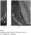
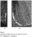
- the two reversible snowboards according to the prior art ( FIG. 1 : Coating 9; FIG. 2 : Coating 8) show extensive flaking of the layer along the cutting edge.
- FIG. 3 Coating 1
- hardly spalling is observed.
- Carbide indexable inserts of geometry SEHW1204AFN with a composition of 90.47 wt.% WC, 8 wt.% Co and 1.53 wt.% TaC / NbC were coated with the CVD coatings Nos. 4 and 3 given in Table 3 No. 8 coated.
- the total layer thickness was about 11 ⁇ m for all tools. Milling operations were carried out with the cutting inserts under the following cutting conditions: Workpiece material: Nodular cast iron GGG70 (strength 680 MPa)
- Working engagement: a e 98 mm
- u e 5 mm
- Carbide indexable inserts of geometry SEHW1204AFN with a composition of 90.47% by weight of WC, 8% by weight of Co and 1.53% by weight of TaC / NbC were coated with the CVD coating No. 5 as shown in Table 3 and coated with the coating No. 10 described above (TiN / MT-Ti (C, N)).
- Indexable inserts with Coating No. 5 were used on the one hand in an unirradiated state and on the other hand after a dry blasting treatment with ZrO 2 as a blasting medium in accordance with Sample S8 in Table 5. Milling operations were carried out with the cutting inserts under the following cutting conditions: Workpiece material: Gray cast iron GG25
- Working engagement: a e 98 mm
- u e 5 mm
- Carbide indexable inserts of geometry SEHW1204AFN with a composition of 90.47% by weight of WC, 8% by weight of Co and 1.53% by weight of TaC / NbC were coated with the CVD coating No. 5 as shown in Table 3 and coated with the coating No. 10 described above (TiN / MT-Ti (C, N)).
- 3 cutting inserts were tested. Milling operations were carried out with the cutting inserts under the following cutting conditions: Workpiece material: Mild steel St37 (strength approx. 500 MPa)
- Working engagement: a e 50 mm
- Got over: u e 350 mm
Description
Die Erfindung betrifft ein Werkzeug mit einem Grundkörper aus Hartmetall, Cermet, Keramik, Stahl oder Schnellarbeitsstahl und einer darauf im CVD-Verfahren aufgebrachten ein- oder mehrlagigen Verschleißschutzbeschichtung, wobei die Verschleißschutzbeschichtung wenigstens eine Ti1-xAlxCyNz-Lage aufweist mit Stöchiometriekoeffizienten 0,70 ≤ x < 1, 0 ≤ y < 0,25 und 0,75 ≤ z < 1,15 und mit einer kristallographischen Vorzugsorientierung. Weiterhin betrifft die Erfindung ein Verfahren zur Herstellung eines solchen Werkzeugs.The invention relates to a tool having a base body made of hard metal, cermet, ceramic, steel or high-speed steel and a single or multi-layer wear protection coating applied thereon in the CVD method, wherein the wear protection coating has at least one Ti 1-x Al x C y N z layer with stoichiometry coefficients 0.70 ≦ x <1, 0 ≦ y <0.25 and 0.75 ≦ z <1.15 and having a crystallographic preferential orientation. Furthermore, the invention relates to a method for producing such a tool.
Schneideinsätze für die Werkstoffbearbeitung, insbesondere für die zerspanende Metallbearbeitung, bestehen aus einem Substratkörper aus Hartmetall, Cermet, Keramik, Stahl oder Schnellarbeitsstahl, der in den meisten Fällen zur Verbesserung der Schneid- und/oder Verschleißeigenschaften mit einer ein- oder mehrlagigen Hartstoffbeschichtung versehen ist. Die Hartstoffbeschichtung besteht aus übereinander angeordneten Lagen monometallischer oder gemischtmetallischer Hartstoffphasen. Beispiele für monometallische Hartstoffphasen sind TiN, TiC, TiCN und Al2O3. Beispiele für gemischtmetallische Phasen, bei denen in einem Kristall ein Metall teilweise durch ein anderes ersetzt ist, sind TiAIN und TiAICN. Beschichtungen der vorgenannten Art werden durch CVD-Verfahren (chemische Dampfphasenabscheidung), PCVD-Verfahren (Plasma-unterstützte CVD-Verfahren) oder durch PVD-Verfahren (physikalische Dampfphasenabscheidung) aufgebracht.Cutting inserts for material processing, in particular for machining metal, consist of a substrate body made of hard metal, cermet, ceramic, steel or high-speed steel, which is provided in most cases to improve the cutting and / or wear properties with a single or multi-layer hard coating. The hard material coating consists of superimposed layers of monometallic or mixed metallic hard material phases. Examples of monometallic hard material phases are TiN, TiC, TiCN and Al 2 O 3 . Examples of mixed metallic phases in which one metal is partially replaced by another in one crystal are TiAIN and TiAICN. Coatings of the aforementioned type are applied by CVD (chemical vapor deposition), PCVD (plasma assisted CVD) or PVD (physical vapor deposition).
Es hat sich gezeigt, dass bestimmte Vorzugsorientierungen des Kristallwachstums bei der Abscheidung im PVD- oder CVD-Verfahren besondere Vorteile haben können, wobei für unterschiedliche Anwendungen des Schneideinsatzes auch unterschiedliche Vorzugsorientierungen bestimmter Lagen einer Beschichtung besonders vorteilhaft sein können. Die Vorzugsorientierung des Wachstums wird in der Regel in Bezug auf die über die Miller-Indizes definierten Ebenen des Kristallgitters angegeben und als kristallographische Textur (z. B. Fasertextur) bezeichnet.It has been found that certain preferred orientations of the crystal growth in the deposition in the PVD or CVD process can have particular advantages, wherein for different applications of the cutting insert also different preferred orientations of certain layers of a coating can be particularly advantageous. The preference orientation of growth is usually in relation to the levels defined above the Miller indices of the crystal lattice and referred to as a crystallographic texture (eg, fiber texture).
Die
Die
Die Offenlegungsschriften
Aus der
Aus der
Mittels PVD-Verfahren hergestellte TiAIN-Beschichtungen mit verschiedenen kristallographischen Vorzugsorientierungen des Kristallwachstums sind bekannt, jedoch sind PVD-Beschichtungen mit kubisch flächenzentriertem Gitter der TiAIN-Beschichtungen im Gegensatz zu CVD-Beschichtungen auf Al-Gehalte von weniger als 67 % beschränkt. TiAIN-Beschichtungen mit einer kristallographischen Vorzugsorientierung der {200}-Ebene bezüglich der Wachstumsrichtung der Kristallite werden als vorteilhaft für die Metallbearbeitung beschrieben (z. B.
Die Aufgabe der vorliegenden Erfindungen bestand in der Bereitstellung von Schneideinsätzen für die spanende Metallbearbeitung, insbesondere die Dreh- und Fräsbearbeitung von Stahl-oder Gusswerkstoffen, die eine gegenüber dem Stand der Technik verbesserte Verschleißbeständigkeit aufweisen.The object of the present invention was to provide cutting inserts for metal cutting, in particular the turning and milling of steel or cast materials, which have a comparison with the prior art improved wear resistance.
Gelöst wird diese Aufgabe durch ein Verfahren zur Herstellung eines Werkzeugs mit einem Grundkörper aus Hartmetall, Cermet, Keramik, Stahl oder Schnellarbeitsstahl und einer darauf im CVD-Verfahren aufgebrachten ein- oder mehrlagigen Verschleißschutzbeschichtung, wobei die Verschleißschutzbeschichtung wenigstens eine Ti1-xAlxCyNz-Lage aufweist mit Stöchiometriekoeffizienten 0,70 ≤ x < 1, 0 ≤ y < 0,25 und 0,75 ≤ z < 1,15 und mit einer Dicke im Bereich von 1 µm bis 25 µm, wobei zur Herstellung der Ti1-xAlxCyNz-Lage
- a) die zu beschichtenden Körper in einem im Wesentlichen zylindrischen CVD-Reaktor platziert werden, der für ein Anströmen der zu beschichtenden Körper mit den Prozessgasen in einer Richtung im Wesentlichen radial zur Längsachse des Reaktors ausgelegt ist,
- b) zwei Vorläufergasgemische (VG1) und (VG2) bereitgestellt werden, wobei
das erste Vorläufergasgemisch (VG1)- 0,005% bis 0,2 Vol.-% TiCl4,
- 0,025% bis 0,5 Vol.-% AlCl3 und
- als Trägergas Wasserstoff (H2) oder ein Gemisch aus Wasserstoff und Stickstoff (H2/N2) enthält und
- 0,1 bis 3,0 Vol.-% wenigstens eines N-Donors, ausgewählt unter Ammoniak (NH3) und Hydrazin (N2H4), und
- als Trägergas Wasserstoff (H2) oder ein Gemisch aus Wasserstoff und Stickstoff (H2/N2) enthält,
- c) die zwei Vorläufergasgemische (VG1, VG2) vor dem Eintritt in die Reaktionszone getrennt gehalten werden und bei einer Prozesstemperatur im CVD-Reaktor im Bereich von 600°C bis 850 °C und einem Prozessdruck im CVD-Reaktor im Bereich von 0,2 bis 18 kPa im Wesentlichen radial zur Längsachse des Reaktors eingeleitet werden, wobei das Verhältnis der Volumengasströme (v̇) der Vorläufergasgemische (VG1, VG2) v̇ (VG1)/ v̇ (VG2) kleiner als 1,5 beträgt.
- a) the bodies to be coated are placed in a substantially cylindrical CVD reactor, which is designed for an influx of the bodies to be coated with the process gases in a direction substantially radially to the longitudinal axis of the reactor,
- b) two precursor gas mixtures (VG1) and (VG2) are provided, wherein
the first precursor gas mixture (VG1)- 0.005% to 0.2% by volume of TiCl 4 ,
- 0.025% to 0.5% by volume AlCl 3 and
- as carrier gas contains hydrogen (H 2 ) or a mixture of hydrogen and nitrogen (H 2 / N 2 ) and
- 0.1 to 3.0% by volume of at least one N donor selected from ammonia (NH 3 ) and hydrazine (N 2 H 4 ), and
- contains as carrier gas hydrogen (H 2 ) or a mixture of hydrogen and nitrogen (H 2 / N 2 ),
- c) the two precursor gas mixtures (VG1, VG2) are kept separate before entering the reaction zone and at a process temperature in the CVD reactor in the range of 600 ° C to 850 ° C and a process pressure in the CVD reactor in the range of 0.2 to 18 kPa are introduced substantially radially to the longitudinal axis of the reactor, wherein the ratio of the volume gas flows ( v̇ ) of the precursor gas mixtures (VG1, VG2) v̇ (VG1) / v̇ (VG2) is less than 1.5.
Im Sinne der vorliegenden Erfindung beziehen sich Vol.-%-Anteile in den Vorläufergasgemischen auf das Gesamtvolumen des in die Reaktionszone eingeleiteten Gasgemisches aus den ersten und zweiten Vorläufergasgemischen.For the purposes of the present invention, percentages by volume in the precursor gas mixtures relate to the total volume of the gas mixture introduced into the reaction zone from the first and second precursor gas mixtures.
Es wurde überraschend gefunden, dass durch die erfindungsgemäße Prozessführung Ti1-xAlxCyNz- und Ti1-xAlxNz-Lagen mit Stöchiometriekoeffizienten 0,70 ≤ x < 1, 0 ≤ y < 0,25 und 0,75 ≤ z < 1,15 und mit kubisch flächenzentriertem Gitter hergestellt werden können, die eine ausgeprägte Vorzugsorientierung des Kristallwachstums bezüglich der {111}-Ebene des Kristallgitters aufweisen. Die erfindungsgemäßen Beschichtungen weisen im Vergleich zu bekannten Beschichtungen mit TiAICN- und TiAIN-Lagen, insbesondere solchen mit Vorzugsorientierung des Kristallwachstums bezüglich der {200}-Ebene des Kristallgitters, überragende Eigenschaften in der Metallbearbeitung auf. Es wurde weiterhin überraschenderweise gefunden, dass man bei einem Schneideinsatz mit einer Beschichtung der hierin beschriebenen Art bei der spanenden Metallbearbeitung, insbesondere bei der Dreh- und Fräsbearbeitung von Stahl- oder Gusswerkstoffen, eine gegenüber bekannten Schneideinsätzen verbesserte Verschleißbeständigkeit und einem breiteren Anwendungsbereich erzielen kann.It has surprisingly been found that the process of the invention Ti 1-x Al x C y N z - and Ti 1-x Al x N z layers with stoichiometric 0.70 ≤ x <1, 0 ≤ y <0.25 and 0.75 ≤ z <1.15 and can be made with face-centered cubic lattice having a pronounced orientation of crystal growth relative to the {111} plane of the crystal lattice. In comparison with known coatings with TiAICN and TiAIN layers, in particular those with preferred orientation of the crystal growth with respect to the {200} plane of the crystal lattice, the coatings according to the invention have outstanding properties in metalworking. It has further been surprisingly found that in a cutting insert having a coating of the type described herein in metal cutting operations, particularly in turning and milling of steel or cast materials, improved wear resistance over a known cutting insert and a wider range of applications can be achieved.
Bei dem erfindungsgemäßen CVD-Verfahren werden zwei Vorläufergasgemische (VG1) und (VG2) bereitgestellt, wobei das erste Vorläufergasgemisch (VG1) die Metalle Ti und Al in der Form ihrer Chloride und Trägergas enthält und das zweite Vorläufergasgemisch (VG2) wenigstens einen N-Donor enthält. Für die Herstellung einer reinen TiAIN-Lage wird in der Regel nur N-Donor Ammoniak (NH3) oder Hydrazin (N2H4) eingesetzt. Für die Herstellung TiAlCN-Lage werden N-Donor und C-Donor eingesetzt, beispielsweise Ammoniak (NH3) im Gemisch mit Ethen (C2H4). Acetonitril (CH3CN) wirkt im erfindungsgemäßen Verfahren überwiegend als C-Donor und wird demzufolge im Gemisch mit einem N-Donor eingesetzt. Je nach gewünschter Stöchiometrie können Gemische mit weiteren N-Donoren und C-Donoren eingesetzt werden. Für das erfindungsgemäße Verfahren ist erforderlich, dass der N-Donor getrennt von den Chloriden der Metalle Ti und Al zugeführt wird, dagegen kann der C-Donor sowohl über das erste Vorläufergasgemisch (VG1) als auch über das zweite Vorläufergasgemisch (VG2) zugeführt werden. In einer weiteren bevorzugten Ausführungsform der Erfindung ist der N-Donor Ammoniak (NH3).The CVD process of the present invention provides two precursor gas mixtures (VG1) and (VG2) wherein the first precursor gas mixture (VG1) contains the metals Ti and Al in the form of their chlorides and carrier gas and the second precursor gas mixture (VG2) contains at least one N-donor contains. For the production of a pure TiAIN layer usually only N-donor ammonia (NH 3 ) or hydrazine (N 2 H 4 ) is used. For the preparation TiAlCN layer N-donor and C-donor are used, for example, ammonia (NH 3 ) in admixture with ethene (C 2 H 4 ). Acetonitrile (CH 3 CN) acts predominantly as a C donor in the process according to the invention and is therefore used in admixture with an N donor. Depending on the desired stoichiometry, mixtures with other N donors and C donors can be used. The process of the present invention requires that the N donor be supplied separately from the chlorides of the metals Ti and Al, while the C donor may be supplied via both the first precursor gas mixture (VG1) and the second precursor gas mixture (VG2). In a further preferred embodiment of the invention, the N-donor is ammonia (NH 3 ).
Das erfindungsgemäß angewendete CVD-Verfahren ist ein MT-CVD-Verfahren bei einer Prozesstemperatur im CVD-Reaktor im Bereich von 600°C bis 850 °C und einem Prozessdruck im Bereich von 0,2 bis 18 kPa. Der CVD-Reaktor ist ein im Wesentlichen zylindrischer Reaktor, der für ein Anströmen der zu beschichtenden Körper mit den Prozessgasen in einer Richtung im Wesentlichen radial zur Längsachse des Reaktors ausgelegt ist, d. h. von der Mittelachse des zylindrischen Reaktors in Richtung der vom Zylindermantel gebildeten Außenwände des Reaktors. Solche zylindrischen Reaktoren sind bekannt und kommerziell erhältlich, beispielsweise die CVD-Beschichtungssysteme des Typs Bernex® BPXpro der Firma lonbond AG Olten, Schweiz.The inventively used CVD process is an MT-CVD process at a process temperature in the CVD reactor in the range of 600 ° C to 850 ° C and a process pressure in the range of 0.2 to 18 kPa. The CVD reactor is a substantially cylindrical reactor designed to flow the bodies to be coated with the process gases in a direction substantially radial to the longitudinal axis of the reactor, ie from the central axis of the cylindrical body Reactor in the direction of the outer wall of the reactor formed by the cylinder jacket. Such cylindrical reactors are known and commercially available, for example the Bernex® BPXpro CVD coating systems from lonbond AG Olten, Switzerland.
Eine wesentliche Verfahrensmaßnahme des erfindungsgemäßen Verfahrens besteht darin, dass die zwei Vorläufergasgemische (VG1) und (VG2) vor dem Eintritt in die Reaktionszone getrennt gehalten werden. Wird dies nicht eingehalten, können die Vorläufergasströme bereits zu früh reagieren, beispielsweise in den Zuführungsleitungen, und die gewünschte Beschichtung wird nicht erzielt.An essential method of the process of the invention is that the two precursor gas mixtures (VG1) and (VG2) are kept separate prior to entering the reaction zone. If this is not done, the precursor gas streams may already react too early, for example in the supply lines, and the desired coating will not be achieved.
Eine weitere wesentliche Verfahrensmaßnahme des erfindungsgemäßen Verfahrens besteht darin, dass das Verhältnis der Volumengasströme (v̇) der Vorläufergasgemische (VG1, VG2) v̇ (VG1) / v̇ (VG2) kleiner als 1,5 beträgt. Wählt man das Verhältnis der Volumengasströme (v̇) der Vorläufergasgemische (VG1, VG2) v̇ (VG1) / v̇ (VG2) größer als 1,5, erhält man nicht die gewünschten Eigenschaften der Ti1-xAlxCyNz-Lage, insbesondere nicht die Vorzugsorientierung des Kristallwachstums bezüglich der {111}-Ebene des Kristallgitters, die hierin als das Verhältnis der Intensitäten der Röntgenbeugungspeaks I{111} / I{200} definiert ist und erfindungsgemäß >1+ h (In h)2 sein soll, wobei h die Dicke der Ti1-xAlxCyNz-Lage in "µm" ist.Another essential method of the method according to the invention is that the ratio of the volume gas flows ( v̇ ) of the precursor gas mixtures (VG1, VG2) v̇ (VG1) / v̇ (VG2) is less than 1.5. If one selects the ratio of the volume gas flows ( v̇ ) of the precursor gas mixtures (VG1, VG2) v̇ (VG1) / v̇ (VG2) greater than 1.5, one does not obtain the desired properties of the Ti 1-x Al x C y N z layer in particular not the preferential orientation of crystal growth with respect to the {111} plane of the crystal lattice defined herein as the ratio of the intensities of the X-ray diffraction peaks I {111} / I {200} and according to the invention should be> 1+ h (In h) 2 where h is the thickness of the Ti 1-x Al x C y N z layer in "μm".
In einer bevorzugten Ausführungsform der Erfindung liegt die Prozesstemperatur im CVD-Reaktor im Bereich von 650°C bis 800 °C, vorzugsweise im Bereich von 675°C bis 750 °C.In a preferred embodiment of the invention, the process temperature in the CVD reactor is in the range of 650 ° C to 800 ° C, preferably in the range of 675 ° C to 750 ° C.
Ist die Prozesstemperatur im CVD-Reaktor zu hoch, werden hohe Gehalte an hexagonalem AIN in der Schicht erhalten, wodurch u.a. die Schichthärte sinkt.If the process temperature in the CVD reactor is too high, high levels of hexagonal AlN will be obtained in the layer, causing i.a. the layer hardness decreases.
Ist die Prozesstemperatur im CVD-Reaktor hingegen zu niedrig, kann die Abscheiderate in einen unwirtschaftlichen Bereich sinken. Zudem werden bei niedrigen Temperaturen Schichten mit Chlor-Gehalten >1 At.-% und geringerer Härte erhalten.On the other hand, if the process temperature in the CVD reactor is too low, the deposition rate may drop to an uneconomic level. In addition, layers with chlorine contents> 1 at.% And lower hardness are obtained at low temperatures.
In einer weiteren bevorzugten Ausführungsform der Erfindung liegt der Prozessdruck im CVD-Reaktor im Bereich von 0,2 bis 7 kPa, vorzugsweise im Bereich von 0,4 bis 1,8 kPa.In a further preferred embodiment of the invention, the process pressure in the CVD reactor is in the range from 0.2 to 7 kPa, preferably in the range from 0.4 to 1.8 kPa.
Ist der Prozessdruck im CVD-Reaktor zu hoch, führt dies zu einer ungleichmäßigen Schichtdicken-Verteilung an den Werkzeugen mit erhöhter Schichtdicke an den Kanten, dem sogenannten Dogbone-Effekt. Zudem werden häufig hohe Anteile an hexagonalem AIN erhalten.If the process pressure in the CVD reactor is too high, this leads to an uneven layer thickness distribution on the tools with increased layer thickness at the edges, the so-called dogbone effect. In addition, high levels of hexagonal AIN are often obtained.
Ein Prozessdruck im CVD-Reaktor kleiner 0,2 kPa ist hingegen technisch schwierig zu realisieren. Zudem ist bei zu niedrigem Prozessdruck die gleichmäßige Beschichtung der Werkzeuge nicht mehr gewährleistet.A process pressure in the CVD reactor smaller than 0.2 kPa, however, is technically difficult to implement. In addition, if the process pressure is too low, uniform coating of the tools is no longer guaranteed.
In einer weiteren bevorzugten Ausführungsform der Erfindung ist das Verhältnis der Volumengasströme (v̇) der Vorläufergasgemische (VG1, VG2) v̇ (VG1)/ v̇ (VG2) kleiner als 1,25, vorzugsweise kleiner als 1,15.In a further preferred embodiment of the invention, the ratio of the volume gas flows ( v̇ ) of the precursor gas mixtures (VG1, VG2) v̇ (VG1) / v̇ (VG2) is less than 1.25, preferably less than 1.15.
Ist das Verhältnis der der Volumengasströme (v̇) der Vorläufergasgemische (VG1, VG2) zu hoch, wird in der Regel eine andere als die erfindungsgemäße {111}-Vorzugsorientierung erhalten.If the ratio of the volumetric gas flows ( v̇ ) of the precursor gas mixtures (VG1, VG2) is too high, then a preference other than the {111} preference orientation according to the invention is obtained.
In einer weiteren bevorzugten Ausführungsform der Erfindung werden die Konzentration von TiCl4 in dem Vorläufergasgemisch (VG1) und die Konzentration von N-Donor in dem Vorläufergasgemisch (VG2) so eingestellt, dass das molare Verhältnis von Ti zu N in den in Stufe c) in den Reaktor einleiteten Volumengasströmen v̇ (VG1) und v̇ (VG2) ≤ 0,25 beträgt.In a further preferred embodiment of the invention, the concentration of TiCl 4 in the precursor gas mixture (VG1) and the concentration of nitrogen donor in the precursor gas mixture (VG2) are adjusted so that the molar ratio of Ti to N in the in step c) in the volume of the gas introduced by the reactor is v̇ (VG1) and v̇ (VG2) ≤ 0.25.
Es wurde überraschend festgestellt, dass man bei einem höheren molaren Verhältnis von Ti zu N der in den Reaktor einleiteten Volumengasströmen v̇ (VG1) und v̇ (VG2) sehr Ti-reiche Lagen erhält, insbesondere bei Verwendung von Ammoniak (NH3) als N-Donor. Es wird vermutet, dass bei einem zu hohen Verhältnis von Ti zu N in den Volumengasströmen die Reaktion des AlCl3 aufgrund von Komplexbildung zwischen TiCl4 und dem N-Donor zurückgedrängt wird.It has surprisingly been found that, given a higher molar ratio of Ti to N, the volumetric gas streams v̇ (VG1) and v̇ (VG2) introduced into the reactor are given very Ti-rich layers, in particular when ammonia (NH 3 ) is used as N 2. donor. It is believed that if the ratio of Ti to N in the bulk gas streams is too high, the reaction of AlCl 3 is suppressed due to complex formation between TiCl 4 and the N donor.
In einer weiteren bevorzugten Ausführungsform der Erfindung enthält das zweite Vorläufergasgemisch (VG2) ≤ 1,0 Vol.-%, vorzugsweise ≤ 0,6 Vol.-% des N-Donors.In a further preferred embodiment of the invention, the second precursor gas mixture (VG2) contains ≦ 1.0 vol .-%, preferably ≦ 0.6 vol .-% of the N-donor.
Ist die Konzentration des N-Donors, gegebenenfalls im Gemisch mit C-Donor, in dem zweiten Vorläufergasgemisch (VG2) zu hoch, so werden die gewünschte Zusammensetzung und kristallographische Vorzugsorientierung nicht erhalten.If the concentration of the N-donor, optionally in admixture with C donor, in the second precursor gas mixture (VG2) is too high, the desired composition and crystallographic preferential orientation will not be obtained.
In einer weiteren bevorzugten Ausführungsform der Erfindung wird die Verschleißschutzbeschichtung einer Strahlbehandlung mit einem partikulären Strahlmittel, vorzugsweise Korund, unter Bedingungen unterzogen, dass die Ti1-xAlxCyNz-Lage nach der Strahlbehandlung Eigenspannungen im Bereich von +300 bis -5000 MPa, vorzugsweise im Bereich von -1 bis -3500 MPa aufweist.In a further preferred embodiment of the invention, the wear protection coating is subjected to a blasting treatment with a particulate blasting agent, preferably corundum, under conditions such that the Ti 1-x Al x C y N z layer after the blasting treatment has residual stresses in the range from +300 to -5000 MPa, preferably in the range of -1 to -3500 MPa.
Ist die Druckeigenspannung der Ti1-xAlxCyNz-Lage zu hoch, so kann es zum Abplatzen der Beschichtung an den Kanten des Werkzeugs kommen.If the residual compressive stress of the Ti 1-x Al x C y N z layer is too high, the coating may flake off at the edges of the tool.
Liegen hingegen Zugeigenspannungen in der Ti1-xAlxCyNz-Lage vor, so wird nicht die optimale Beständigkeit des Werkzeugs gegen thermomechanische Wechselbeanspruchung bzw. gegen die Ausbildung von Kammrissen erzielt.However, if residual tensile stresses are present in the Ti 1-x Al x C y N z layer, the optimum resistance of the tool to thermomechanical alternating stress or to the formation of comb cracks is not achieved.
Zum Einbringen der bevorzugten Eigenspannungen in die Ti1-xAlxCyNz-Lage lassen sich mit Vorteil Trocken- oder Nassstrahlbehandlung einsetzen. Die Strahlbehandlung wird zweckmäßigerweise bei einem Strahlmitteldruck von 1 bar bis 10 bar durchgeführt.To introduce the preferred residual stress in the Ti 1-x Al x C y N z -layer can be used with advantage dry or wet blasting treatment. The blast treatment is conveniently carried out at a fluid jet pressure of 1 bar to 10 bar.
Die für das Einbringen der erfindungsgemäßen Eigenspannungen erforderliche Dauer der Strahlbehandlung und der erforderliche Strahldruck sind Parameter, die der Fachmann innerhalb der hierin definierten Grenzen durch einfache Experimente ermitteln kann. Eine pauschale Angabe ist hier nicht möglich, da die sich einstellenden Eigenspannungen nicht nur von der Dauer der Strahlbehandlung und dem Strahldruck abhängen, sondern auch von dem Aufbau und der Dicke der Gesamtbeschichtung. Allerdings hat der Strahldruck dabei im Vergleich zur Strahldauer den wesentlich größeren Einfluss auf die Veränderung der Eigenspannungen in der Beschichtung und dem Substratkörper. Geeignete Strahlbehandlungsdauern liegen üblicherweise im Bereich von 10 bis 600 Sekunden.The duration of the jet treatment required for introducing the residual stresses according to the invention and the required jet pressure are parameters which the person skilled in the art can determine by simple experiments within the limits defined herein. A blanket statement is not possible here, since the self-adjusting residual stresses depend not only on the duration of the blast treatment and the jet pressure, but also on the structure and the thickness of the overall coating. However, the jet pressure has the much greater influence on the change in the residual stresses in the coating and the substrate body compared to the jet duration. Suitable jet treatment times are usually in the range of 10 to 600 seconds.
Der Strahlwinkel, d. h. der Winkel zwischen dem Behandlungsstrahl und der Oberfläche des Werkzeugs, hat ebenfalls einen wesentlichen Einfluss auf den Eintrag von Eigenspannungen. Bei einem Strahlwinkel von 90° erfolgt der maximale Eintrag von Druckeigenspannungen. Geringere Strahlwinkel, d. h. schräges Einstrahlen des Strahlmittels, führen zu einer stärkeren Abrasion der Oberfläche und geringerem Druckeigenspannungseintrag.The beam angle, d. H. the angle between the treatment beam and the surface of the tool also has a significant influence on the introduction of residual stresses. At a beam angle of 90 °, the maximum entry of compressive residual stresses occurs. Lower beam angles, d. H. oblique irradiation of the blasting abrasive, lead to a stronger abrasion of the surface and lower pressure self-tension entry.
Die Erfindung umfasst auch ein Werkzeug mit einem Grundkörper aus Hartmetall, Cermet, Keramik, Stahl oder Schnellarbeitsstahl und einer darauf im CVD-Verfahren aufgebrachten ein- oder mehrlagigen Verschleißschutzbeschichtung, wobei die Verschleißschutzbeschichtung wenigstens eine Ti1-xAlxCyNz-Lage aufweist mit Stöchiometriekoeffizienten 0,70 ≤ x < 1, 0 ≤ y < 0,25 und 0,75 ≤ z < 1,15, dadurch gekennzeichnet, dass
die Ti1-xAlxCyNz-Lage eine Dicke im Bereich von 1 µm bis 25 µm hat und eine kristallographische Vorzugsorientierung aufweist, die durch ein Verhältnis der Intensitäten der Röntgenbeugungspeaks der kristallografischen {111}-Ebene und der {200}-Ebene charakterisiert ist, bei dem I{111} / I{200} > 1+h (In h)2, wobei h die Dicke der Ti1-xAlxCyNz-Lage in "µm" ist.The invention also encompasses a tool having a base body made of cemented carbide, cermet, ceramic, steel or high-speed steel and a single-layer or multi-layer wear protection coating applied thereto by the CVD method, wherein the wear protection coating has at least one Ti 1-x Al x C y N z layer having stoichiometry coefficients 0.70 ≦ x <1, 0 ≦ y <0.25 and 0.75 ≦ z <1.15, characterized in that
the Ti 1-x Al x C y N z layer has a thickness in the range of 1 μm to 25 μm and has a crystallographic preferential orientation characterized by a ratio of the intensities of the X-ray diffraction peaks of the {111} crystallographic plane and {200} Is characterized in that I {111} / I {200}> 1 + h (In h) 2 , where h is the thickness of the Ti 1-x Al x C y N z layer in "μm".
In einer bevorzugten Ausführungsform der Erfindung beträgt die Halbwertsbreite (FWHM) des Röntgenbeugungspeaks der {111}-Ebene der Ti1-xAlxCyNz-Lage < 1°, vorzugsweise < 0,6°, besonders bevorzugt < 0,45°.In a preferred embodiment of the invention, the half-width (FWHM) of the X-ray diffraction peak of the {111} plane of the Ti 1-x Al x C y N z layer is <1 °, preferably <0.6 °, particularly preferably <0.45 °.
Ein zu hohe Halbwertsbreite (FWHM) des Röntgenbeugungspeaks der {111}-Ebene der Ti1-xAlxCyNz-Lage deutet auf geringere Korngrößen der kubisch flächenzentrierten (fcc) Phase oder gar auf Anteile amorpher Phasen hin. Dies hat sich in den bisherigen Tests als nachteilig für die Verschleißbeständigkeit erwiesen.Too high a full width at half maximum (FWHM) of the X-ray diffraction peak of the {111} plane of the Ti 1-x Al x C y N z layer indicates smaller grain sizes of the cubic face centered (fcc) phase or even portions of amorphous phases. This has proven in the previous tests as a disadvantage for the wear resistance.
In einer weiteren bevorzugten Ausführungsform der Erfindung weist die Ti1-xAlxCyNz-Lage wenigstens 90 Vol.-% Ti1-xAlxCyNz-Phase mit kubisch flächenzentriertem (fcc) Gitter, vorzugsweise wenigstens 95 Vol.-% Ti1-xAlxCyNz-Phase mit kubisch flächenzentriertem (fcc) Gitter, besonders bevorzugt wenigstens 98 Vol.-% Ti1-xAlxCyNz-Phase mit kubisch flächenzentriertem (fcc) Gitter auf.In a further preferred embodiment of the invention, the Ti 1-x Al x C y N z layer has at least 90 vol.% Ti 1-x Al x C y N z phase with cubic face-centered (fcc) grating, preferably at least 95 Vol .-% Ti 1-x Al x C y N z phase with cubic face centered (fcc) lattice, more preferably at least 98 vol% Ti 1-x Al x C y N z phase with face-centered cubic (fcc) Grid on.
Ist der Anteil an Ti1-xAlxCyNz-Phase mit kubisch flächenzentriertem (fcc) Gitter zu gering, wird eine geringere Verschleißbeständigkeit beobachtet.If the proportion of Ti 1-x Al x C y N z phase with cubic face centered (fcc) lattice is too small, less wear resistance is observed.
In einer weiteren bevorzugten Ausführungsform der Erfindung weist die Ti1-xAlxCyNz-Lage Stöchiometriekoeffizienten 0,70 ≤ x < 1, y = 0 und 0,95 ≤ z < 1,15 auf.In a further preferred embodiment of the invention, the Ti 1 -x Al x C y N z layer has stoichiometric coefficients 0.70 ≦ x <1, y = 0 and 0.95 ≦ z <1.15.
In einer weiteren bevorzugten Ausführungsform der Erfindung weist die Ti1-xAlxCyNz-Lage eine Dicke im Bereich von 3 µm bis 20 µm, vorzugsweise im Bereich von 4 bis 15 µm auf.In a further preferred embodiment of the invention, the Ti 1-x Al x C y N z layer has a thickness in the range from 3 μm to 20 μm, preferably in the range from 4 to 15 μm.
Ist die Dicke der die Ti1-xAlxCyNz-Lage zu gering, ist die Verschleißbeständigkeit des Werkzeugs nicht ausreichend.If the thickness of the Ti 1-x Al x C y N z layer is too small, the wear resistance of the tool is insufficient.
Ist die Dicke der die Ti1-xAlxCyNz-Lage hingegen zu hoch, kann es aufgrund der thermischen Eigenspannungen nach der Beschichtung zum Abplatzen der Schicht kommen.If, however, the thickness of the Ti 1-x Al x C y N z layer is too high, the layer may flake off due to the internal thermal stresses after the coating.
In einer weiteren bevorzugten Ausführungsform der Erfindung beträgt das Verhältnis der Intensitäten der Röntgenbeugungspeaks der kristallografischen {111}-Ebene und der (200)-Ebene der Ti1-xAlxCyNz-Lage > 1+(h+3)x(In h)2.In another preferred embodiment of the invention, the ratio of the intensities of the X-ray diffraction peaks of the {111} crystallographic plane and the (200) plane of the Ti 1-x Al x C y N z layer is> 1+ (h + 3) x (In h) 2 .
In einer weiteren bevorzugten Ausführungsform der Erfindung weist die Ti1-xAlxCyNz-Lage eine Vickers-Härte (HV) > 2300 HV, vorzugsweise > 2750 HV, besonders bevorzugt > 3000 HV auf.In a further preferred embodiment of the invention, the Ti 1-x Al x C y N z layer has a Vickers hardness (HV)> 2300 HV, preferably> 2750 HV, particularly preferably> 3000 HV.
In einer weiteren bevorzugten Ausführungsform der Erfindung ist zwischen dem Grundkörper und der Ti1-xAlxCyNz-Lage wenigstens eine weitere Hartstofflage angeordnet, ausgewählt unter einer TiN-Lage, einer mittels Hochtemperatur-CVD (CVD) oder Mitteltemperatur-CVD (MT-CVD) abgeschiedenen TiCN-Lage, einer Al2O3-Lage und Kombinationen davon. Besonders bevorzugt ist es, die weiteren Lagen im gleichen Temperaturbereich, d. h. durch Mitteltemperatur-CVD (MT-CVD), aufzubringen wie die Ti1-xAlxCyNz-Lage, um unwirtschaftliche Abkühlzeiten zu vermeiden.In a further preferred embodiment of the invention, at least one further layer of hard material is arranged between the base body and the Ti 1-x Al x C y N z layer, selected from among a TiN layer, one by means of high-temperature CVD (CVD) or medium-temperature CVD (MT-CVD) deposited TiCN layer, an Al 2 O 3 layer and combinations thereof. It is particularly preferable to apply the further layers in the same temperature range, ie by medium-temperature CVD (MT-CVD), as the Ti 1-x Al x C y N z layer in order to avoid uneconomical cooling times.
In einer weiteren bevorzugten Ausführungsform der Erfindung ist über der Ti1-xAlxCyNz-Lage wenigstens eine weitere Hartstofflage angeordnet ist, vorzugsweise wenigstens eine Al2O3-Lage der Modifikation γ-Al2O3, κ-Al2O3 oder α-Al2O3, wobei die Al2O3-Lage mittels Hochtemperatur-CVD (CVD) oder Mitteltemperatur-CVD (MT-CVD) abgeschieden ist. Besonders bevorzugt ist es, die Aluminiumoxid-Lage aus den oben genannten Gründen im gleichen Temperaturbereich, d. h. durch Mitteltemperatur-CVD (MT-CVD), aufzubringen wie die Ti1-xAlxCyNz-Lage, um mögliche Phasenumwandlungen der Ti1-xAlxCyNz-Lage zu vermeiden. Verfahren zur Herstellung von γ-Al2O3, κ-Al2O3 oder α-Al2O3-Schichten im Bereich von 600 bis 850°C sind dem Fachmann bekannt, beispielsweise aus
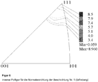
In einer weiteren bevorzugten Ausführungsform ist die kristallographische Vorzugsorientierung der {111}-Ebene der fcc-Ti1-xAlxCyNz-Lage derart ausgeprägt, dass sich das röntgenographisch oder mittels EBSD gemessene absolute Maximum der {111}-Intensität der fcc-Ti1-xAlxCyNz-Lage innerhalb eines Winkelbereichs von α = ±10°, bevorzugt innerhalb α = ±5°, besonders bevorzugt innerhalb α = ±1° befindet, ausgehend von der Normalenrichtung der Probenoberfläche. Maßgeblich hierbei ist der Schnitt durch die {111}-Polfigur des fcc-Ti1-xAlxCyNz nach Integration der Intensitäten über den Azimut-Winkel β (Rotationswinkel um die Probenoberflächennormale).In a further preferred embodiment, the preferred crystallographic orientation of the {111} plane of the fcc-Ti 1-x Al x C y N z -layer is so pronounced that the measured X-ray crystallography or by EBSD absolute maximum of the {111} intensity of the fcc-Ti 1-x Al x C y N z position within an angular range of α = ± 10 °, preferably within α = ± 5 °, particularly preferably within α = ± 1 °, starting from the normal direction of the sample surface. Decisive in this case is the section through the {111} pole figure of the fcc-Ti 1-x Al x C y N z after integration of the intensities over the azimuth angle β (rotation angle around the sample surface normal).
- Figur 1:FIG. 1:
- Schneidkante einer Wendeschneidplatte mit Beschichtung Nr. 9 nach dem Stand der Technik nach einem Drehversuch;Cutting edge of an indexable insert with coating no. 9 according to the prior art after a rotation test;
- Figur 2:FIG. 2:
- Schneidkante einer Wendeschneidplatte mit Beschichtung Nr. 8 nach dem Stand der Technik nach einem Drehversuch;Cutting edge of an indexable insert with coating no. 8 according to the prior art after a rotation test;
- Figur 3:FIG. 3:
- Schneidkante einer Wendeschneidplatte mit erfindungsgemäßer Ti1-xAlxCyNz-Beschichtung Nr. 1 nach einem Drehversuch;Cutting edge of an indexable insert with inventive Ti 1-x Al x C y N z coating No. 1 after a rotation test;
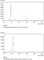
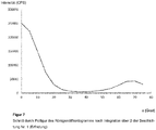
- Figur 4:FIG. 4:
- Röntgendiffraktogramm der Beschichtung Nr. 4 (Erfindung);X-ray diffractogram of Coating No. 4 (Invention);
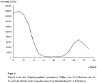
- Figur 5:FIG. 5:
- Röntgendiffraktogramm der Beschichtung Nr. 8 (Stand der Technik);X-ray diffractogram of Coating No. 8 (prior art);
- Figur 6:FIG. 6:
- Inverse Polfigur für die Normalenrichtung der Beschichtung Nr. 1 (Erfindung);Inverse pole figure for the normal direction of the coating No. 1 (Invention);
- Figur 7:FIG. 7:
- Schnitt durch Polfigur des Röntgendiffraktogramms nach Integration über β der Beschichtung Nr. 1 (Erfindung);Section through pole figure of the X-ray diffractogram after integration over β of coating No. 1 (invention);
- Figur 8:FIG. 8:
- Schnitt durch die Polfigur des Röntgendiffraktogramms nach Integration über β der Beschichtung Nr. 2 (Erfindung).Section through the pole figure of the X-ray diffractogram after integration over β of the coating no. 2 (invention).
Als Substratkörper wurden in diesen Beispielen Hartmetall-Wendeschneidplatten der Geometrie CNMA120412 mit einer Zusammensetzung von 86,5 Gew.-% WC, 5,5 Gew.-% Co, 2 Gew.-% TiC, 6 Gew.-% (NbC+TaC) und mit einer mischcarbidfreien Randzone verwendet.As substrate body, carbide indexable inserts of the geometry CNMA120412 with a composition of 86.5% by weight of WC, 5.5% by weight of Co, 2% by weight of TiC, 6% by weight (NbC + TaC ) and used with a mixed carbide-free edge zone.
Zur Beschichtung der Hartmetall-Wendeschneidplatten wurde eine CVD-Beschichtungsanlage des Typs Bernex BPX325S mit einer Reaktorhöhe von 1250 mm und einem Reaktordurchmesser von 325 mm eingesetzt. Der Gasfluss erfolgte radial zur Längsachse des Reaktors.To coat carbide indexable inserts, a Bernex BPX325S CVD coater with a reactor height of 1250 mm and a reactor diameter of 325 mm was used. The gas flow was radial to the longitudinal axis of the reactor.
Zur Anbindung der erfindungsgemäßen Ti1-xAlxCyNz-Lagen sowie der Vergleichslagen wurde unmittelbar auf dem Hartmetall-Substrat zunächst eine etwa 0,3 µm dicke TiN-Lage oder TiCN-Lage mittels CVD unter den in Tabelle 1 angegebenen Abscheidebedingungen aufgebracht:
Zur Herstellung der erfindungsgemäßen Ti1-xAlxCyNz-Lagen wurden ein erstes Vorläufergasgemisch (VG1) mit den Ausgangsverbindungen TiCl4 und AlCl3 und ein zweites Vorläufergasgemisch (VG2) mit der Ausgangsverbindung NH3 als reaktive Stickstoffverbindung voneinander getrennt in den Reaktor eingeleitet, so dass eine Vermischung der beiden Gasströme erst bei Eintritt in die Reaktionszone erfolgte.To produce the Ti 1-x Al x C y N z layers according to the invention, a first precursor gas mixture (VG1) with the starting compounds TiCl 4 and AlCl 3 and a second precursor gas mixture were prepared (VG2) with the starting compound NH 3 as a reactive nitrogen compound separated from each other into the reactor, so that a mixing of the two gas streams took place only when it enters the reaction zone.
Die Volumengasströme der Vorläufergasgemische (VG1) und (VG2) wurden so eingestellt, dass bei Herstellung erfindungsgemäßer Beschichtungen das Verhältnis der Volumengasströme v̇ (VG1) / v̇ (VG2) kleiner als 1,5 war. Die Parameter bei der Herstellung erfindungsgemäßer Ti1-xAlxCyNz-Beschichtungen sowie von Vergleichsbeschichtungen sind in Tabelle 3 wiedergegeben.The volume gas flows of the precursor gas mixtures (VG1) and (VG2) were adjusted so that when preparing coatings according to the invention, the ratio of the volume gas flows v̇ (VG1) / v̇ (VG2) was less than 1.5. The parameters in the preparation of inventive Ti 1-x Al x C y N z coatings and comparative coatings are shown in Table 3.
Als weitere Vergleichsbeispiele nach dem Stand der Technik wurden Hartmetall-Wendeschneidplatten mit
a) einem 12 µm dicken Lagensystem der Abfolge TiN / MT-Ti(C,N) / TiN (Beschichtung Nr. 9) und
b) einem 5 µm dicken Lagensystem der Abfolge TiN / MT-Ti(C,N) (Beschichtung Nr. 10) beschichtet. Hierfür wurden die Abscheidebedingungen gemäß nachfolgender Tabelle 2 verwendet:
a) a 12 μm thick layer system of the sequence TiN / MT-Ti (C, N) / TiN (coating no. 9) and
b) a 5 .mu.m thick layer system of the sequence TiN / MT-Ti (C, N) (coating no. 10) coated. For this purpose, the deposition conditions according to Table 2 below were used:
Zur Untersuchung von Zusammensetzung, Textur, Eigenspannungen und Härte der Beschichtungen wurden folgende Verfahren verwendet.To study the composition, texture, residual stresses and hardness of the coatings, the following procedures were used.
Zur Bestimmung der kristallographischen Vorzugsorientierung können sowohl Verfahren der Röntgenbeugung (XRD) als auch Elektronenbeugung, insbesondere EBSD, angewendet werden. Zur sicheren Bestimmung einer Vorzugsorientierung sind Beugungsmessungen an Reflexen einzelner Flächen {hkl} nicht geeignet, sondern es muss die Orientierungsdichtefunktion (ODF) ermittelt werden. Deren Darstellung in Form einer inversen Polfigur zeigt die Lage und Schärfe einer eventuell vorhandenen Fasertextur. Die Orientierungsdichtefunktion muss entweder aus statistisch ausreichend vielen Einzelorientierungsmessungen konstruiert (bei EBSD) oder aus Messungen einer Mindestanzahl von Polfiguren an verschiedenen Reflexen {hkl} (bei XRD) berechnet werden. Siehe hierzu:
Bei den erfindungsgemäßen Ti1-xAlxCyNz-Schichten wurde durch XRD-Messung eines Polfiguren-Satzes und ODF-Berechnung verifiziert, dass eine Fasertextur mit Faserachse entweder genau in <111>-Richtung oder in einer kristallographischen Richtung mit <10° Winkelabweichung von <111> vorliegt. Zur Quantifizierung dieser Textur kann das Intensitäts-Verhältnis der {111}- und {200}-Reflexe aus θ-2θ-Messungen herangezogen werden. Die Lage der Faserachse kann aus der inversen Polfigur oder der röntgenographisch gemessenen Polfigur des {111}-Reflexes ermittelt werden.In the Ti 1-x Al x C y N z layers of the present invention, it was verified by XRD measurement of a pole figure set and ODF calculation that a fiber texture with fiber axis was either exactly in the <111> direction or in a crystallographic direction with < 10 ° angle deviation of <111> is present. To quantify this texture, the intensity ratio of the {111} and {200} reflections from θ-2θ measurements can be used. The position of the fiber axis can be determined from the inverse pole figure or the X-ray measured pole figure of the {111} -reflexes.
Röntgenbeugungsmessungen wurden an einem Diffraktometer des Typs GE Sensing & Inspection Technologies PTS3003 unter Verwendung von CuKα-Strahlung durchgeführt. Für θ-2θ-Eigenspannungs- und Polfigurmessungen wurde eine Parallelstrahloptik verwendet, die primärseitig aus einer Polykapillare und einem 2mm-Pinhole als Kollimator bestand. Sekundärseitig wurde ein Parallelplatten-Kollimator mit 0,4° Divergenz und ein Nickel Kβ-Filter verwendet.X-ray diffraction measurements were taken on a GE Sensing & Inspection Technologies PTS3003 diffractometer using CuKα radiation. For θ-2θ residual stress and pole figure measurements a parallel beam optic was used, which consisted on the primary side of a polycapillary and a 2 mm pinhole as a collimator. On the secondary side, a parallel plate collimator with 0.4 ° divergence and a nickel K β filter was used.
Peakintensitäten und -halbwertsbreiten wurden anhand von θ-2θ-Messungen bestimmt. Nach Abzug des Untergrundes wurden Pseudo-Voigt-Funktionen an die Messdaten gefittet, wobei der Kα2-Abzug mittels Kα1/Kα2-Dublett-Anpassung erfolgte. Die in Tabelle 4 aufgeführten Werte der Intensitäten und Halbwertsbreiten beziehen sich auf die derart angefitteten Kα1-Inteferenzen. Die Gitterkonstanten sind nach dem Vergardschen Gesetz unter Annahme der Gitterkonstanten von TiN und AIN aus den PDF-Karten 38-1420 bzw. 46-1200 berechnet.Peak intensities and half-widths were determined from θ-2θ measurements. After subtracting the background, pseudo-Voigt functions were fitted to the measured data, the Kα 2 withdrawal taking place by means of Kα 1 / Kα 2 doublet adaptation. The values of the intensities and half-widths listed in Table 4 relate to the Kα 1 -intefeions thus added. The lattice constants are calculated according to the Vergard law, assuming the lattice constants of TiN and AIN from the PDF maps 38-1420 and 46-1200, respectively.
Die {101}- bzw. {202}-Interferenzen von hexagonalem AIN und der {111}- bzw. {222}-Reflex von kubischem Ti1-xAlxCyNz können sich je nach chemischer Zusammensetzung mehr oder weniger stark überlagern. Lediglich die Interferenz der {200}-Ebene des kubischen Ti1-xAlxCyNz wird durch keine weiteren Interferenzen, wie z. B. durch den Substratkörper oder darüber oder darunter angeordnete Lagen, überlagert und besitzt für regellose Orientierung die höchste Intensität.The {101} or {202} interferences of hexagonal AIN and the {111} or {222} reflections of cubic Ti 1-x Al x C y N z can vary more or less depending on the chemical composition overlap. Only the interference of the {200} plane of the cubic Ti 1-x Al x C y N z is by no further interference, such as B. by the substrate body or above or below arranged layers superimposed and has for random orientation the highest intensity.
Zur Beurteilung des Volumenanteils an hexagonalem AIN im Messvolumen und zur Vermeidung von Fehlinterpretationen bezüglich der {111}- und {200}-Intensitäten des kubischen Ti1-xAlxCyNz, wurden Messungen (θ-2θ-Scans) unter zwei verschiedenen Kippwinkeln ψ (ψ = 0° und ψ = 54,74°) durchgeführt. Da der Winkel zwischen den Ebenennormalen von {111} und {200} etwa 54,74° beträgt, ergibt sich bei einer starken {111}-Fasertextur ein Intensitätsmaximum des {200}-Reflexes bei dem Kippwinkel ψ = 54,74°, während die Intensität des {111}-Reflexes gegen Null geht. Umgekehrt erhält man bei dem Kippwinkel ψ = 54,74° ein starkes Intensitätsmaximum des {111}-Reflexes bei einer starken {200}-Fasertextur, während die Intensität des {200}-Reflexes gegen Null geht.To evaluate the volume fraction of hexagonal AlN in the measurement volume and to avoid misinterpretations of the {111} and {200} cubic Ti 1-x Al x C y N z intensities, measurements (θ-2θ scans) were taken under two different tilt angles ψ (ψ = 0 ° and ψ = 54.74 °) carried out. Since the angle between the plane normals of {111} and {200} is about 54.74 °, with a strong {111} fiber texture, an intensity maximum of the {200} reflection at the tilt angle ψ = 54.74 ° results the intensity of the {111} reflection approaches zero. Conversely, at the tilt angle ψ = 54.74 °, a strong intensity maximum of the {111} reflection is obtained for a strong {200} fiber texture, while the intensity of the {200} reflection approaches zero.
Für die gemäß den Beispielen hergestellten texturierten Schichten kann auf diese Weise überprüft werden, ob die gemessene Intensität bei 2θ ≈ 38,1° vornehmlich der kubisch flächenzentrierten Ti1-xAlxCyNz-Phase zuzuordnen ist oder ob größere Anteile von hexagonalem AIN in der Schicht enthalten sind. Sowohl Röntgenbeugungsmessungen als auch EBSD-Messungen zeigen übereinstimmend nur sehr geringe Anteile hexagonaler AIN-Phase in den erfindungsgemäßen Schichten.For the textured layers produced according to the examples, it can be checked in this way whether the measured intensity at 2θ ≈38.1 ° is attributable primarily to the face-centered cubic Ti 1-x Al x C y N z phase or larger fractions of hexagonal AIN are included in the layer. Both X-ray diffraction measurements and EBSD measurements consistently show only very small proportions of hexagonal AIN phase in the layers according to the invention.
Polfiguren des {111}-Reflexes wurden bei 2θ = 38,0° über einen Winkelbereich von 0°<α<75° (Inkrement 5°) und 0°<β<360° (Inkrement 5°) bei kreisförmiger Anordnung der Messpunkte erstellt. Die Intensitätsverteilung aller gemessenen und rückgerechneten Polfiguren war annähernd rotationssymmetrisch, d.h. die untersuchten Schichten wiesen Fasertexturen auf. Zur Überprüfung der Vorzugsorientierung wurden zusätzlich zur {111}-Polfigur an den {200}- und {220}-Reflexen Polfiguren gemessen. Die Orientierungsdichte-Verteilungsfunktion (ODF) wurde mit der Software LaboTex3.0 der Firma LaboSoft, Polen, berechnet und die Vorzugsorientierung als inverse Polfigur dargestellt. Bei den erfindungsgemäßen Schichten befand sich das Intensitätsmaximum in <111>-Richtung oder ≤ 10° Winkelabweichung von <111>.Pole figures of the {111} reflection were generated at 2θ = 38.0 ° over an angular range of 0 ° <α <75 ° (increment 5 °) and 0 ° <β <360 ° (increment 5 °) with a circular arrangement of the measurement points , The intensity distribution of all measured and recalculated pole pieces was approximately rotationally symmetric, i. the examined layers had fiber textures. To check the preference orientation, pole figures were measured on the {200} and {220} reflections in addition to the {111} pole figure. The orientation density distribution function (ODF) was calculated using the LaboTex 3.0 software from LaboSoft, Poland, and the preferred orientation is shown as an inverse pole figure. In the layers according to the invention, the intensity maximum was in the <111> direction or ≤ 10 ° angle deviation of <111>.
Für die Eigenspannungsanalysen nach der sin2ψ-Methode wurde die {222}-Interferenz der kubisch flächenzentrierten Ti1-xAlxCyNz-Lage verwendet und unter 25 ψ-Winkeln von -60° bis 60° (Inkrement 5°) vermessen. Nach Untergrundabzug, Lorentz-Polarisation-Korrektur und Kα2-Abzug (Rachinger-Trennung) wurden die Linienlagen der Interferenzen mittels Anpassung von Profilfunktionen an die Messdaten bestimmt. Die verwendeten elastischen Kostanten waren ½s2 = 1,93 TPa-1 und s1 = -0,18 TPa-1. Die Eigenspannung in der WC-Phase des Hartmetall-Substrats wurde in gleicher Weise anhand der {201}-Interferenz unter Verwendung der elastischen Konstanten ½s2 = 1,66 TPa-1 und s1 = -0,27 TPa-1 bestimmt.For the sin 2 ψ-method residual stress analysis, the {222} interference of the cubic face-centered Ti 1-x Al x C y N z layer was used and at 25 ψ angles from -60 ° to 60 ° (Increment 5 °). After background subtraction, Lorentz polarization correction and Kα 2 withdrawal (Rachinger separation), the line positions of the interferences were determined by adapting profile functions to the measured data. The elastic constants used were ½s 2 = 1.93 TPa -1 and s 1 = -0.18 TPa -1 . The residual stress in the WC phase of the cemented carbide substrate was determined in the same way by {201} interference using the elastic constant ½s 2 = 1.66 TPa -1 and s 1 = -0.27 TPa -1 .
Eigenspannungen werden üblicherweise in der Einheit Megapascal (MPa) angegeben, wobei Zugeigenspannungen mit einem positiven Vorzeichen (+) und Druckeigenspannungen mit einem negativen Vorzeichen (-) bezeichnet werden.Residual stresses are usually expressed in units of megapascals (MPa), denoting residual stresses with a positive sign (+) and compressive residual stresses with a negative sign (-).
EDX-Messungen wurden an einem Rasterelektronenmikroskop Supra 40 VP der Firma Carl Zeiss bei 15 kV Beschleunigungsspannung mit einem EDX-Spektrometer Typ INCA x-act der Firma Oxford Instruments, UK, durchgeführt.EDX measurements were carried out on a
Die Messung der Mikrohärte erfolgte nach DIN EN ISO 14577-1 und -4 mit einem Universalhärteprüfer Fischerscope H100 der Firma Helmut Fischer GmbH, Sindelfingen, Deutschland, an einem Querschliff der beschichteten Körper.The microhardness was measured according to DIN EN ISO 14577-1 and -4 using a universal hardness tester Fischerscope H100 from Helmut Fischer GmbH, Sindelfingen, Germany, on a cross-section of the coated body.
Die in den Beispielen beschichteten Hartmetall-Wendeschneidplatten wurden nach der CVD-Beschichtung einer Druckluft-Trockenstrahlbehandlung unterzogen. Die Eigenspannungen in der Ti1-xAlxCyNz-Schicht und im Substrat (WC) wurden vor und nach der Strahlbehandlung gemessen. Die verwendeten Strahlparameter und die gemessenen Eigenspannungswerte sind in Tabelle 5 angegeben.
** n.g. = nicht gemessen
** ng = not measured
Hartmetall-Wendeschneidplatten der Geometrie CNMA120412 mit einer Zusammensetzung von 86,5 Gew.-% WC, 5,5 Gew.-% Co, 2 Gew.-% TiC, 6 Gew.-% (NbC+TaC) und mit einer mischcarbidfreien Randzone wurden mit den in Tabelle 3 angegebenen CVD-Beschichtungen Nr. 1 und Nr. 8 sowie mit der oben beschriebenen Beschichtung Nr. 9 (TiN / MT-Ti(C,N) / TiN) beschichtet. Die Gesamtschichtdicke betrug bei allen Werkzeugen etwa 12 µm. Mit den Schneideinsätzen wurden Längsdrehbearbeitungen unter folgenden Schnittbedingungen durchgeführt:
Die
Hartmetall-Wendeschneidplatten der Geometrie SEHW1204AFN mit einer Zusammensetzung von 90,47 Gew.-% WC, 8 Gew.-% Co und 1,53 Gew.-% TaC/NbC wurden mit den in Tabelle 3 angegebenen CVD-Beschichtungen Nr. 4 und Nr. 8 beschichtet. Die Gesamtschichtdicke betrug bei allen Werkzeugen etwa 11 µm. Mit den Schneideinsätzen wurden Fräsoperationen unter folgenden Schnittbedingungen durchgeführt:
Anschließend wurde die maximale Verschleissmarkenbreite vB,max an der Hauptschneide nach 3200 m Fräsweg bestimmt:
Hartmetall-Wendeschneidplatten der Geometrie SEHW1204AFN mit einer Zusammensetzung von 90,47 Gew.-% WC, 8 Gew.-% Co und 1,53 Gew.-% TaC/NbC wurden mit der in Tabelle 3 angegebenen CVD-Beschichtung Nr. 5 sowie mit der oben beschriebenen Beschichtung Nr. 10 (TiN / MT-Ti(C,N)) beschichtet. Wendeschneidplatten mit Beschichtung Nr. 5 wurden einerseits in ungestrahltem Zustand und andererseits nach einer Trockenstrahlbehandlung mit ZrO2 als Strahlmittel gemäß Probe S8 in Tabelle 5 eingesetzt. Mit den Schneideinsätzen wurden Fräsoperationen unter folgenden Schnittbedingungen durchgeführt:
Anschließend wurde die mittlere Verschleissmarkenbreite vB und die Anzahl der Kammrisse an der Hauptschneide nach 2400 m Fräsweg bestimmt:
Hartmetall-Wendeschneidplatten der Geometrie SEHW1204AFN mit einer Zusammensetzung von 90,47 Gew.-% WC, 8 Gew.-% Co und 1,53 Gew.-% TaC/NbC wurden mit der in Tabelle 3 angegebenen CVD-Beschichtung Nr. 5 sowie mit der oben beschriebenen Beschichtung Nr. 10 (TiN / MT-Ti(C,N)) beschichtet. Es wurden je Beschichtungsvariante 3 Schneideinsätze getestet. Mit den Schneideinsätzen wurden Fräsoperationen unter folgenden Schnittbedingungen durchgeführt:
Anschließend wurde die Anzahl der Kammrisse an der Hauptschneide nach 3200 m Fräsweg bestimmt:
Claims (17)
- A process for the production of a tool having a base body of cemented carbide, cermet, ceramic, steel or high speed steel and a single-layer or multi-layer wear-protection coating applied thereto in a CVD process, wherein the wear-protection coating has at least one
Ti1-xAlxCyNz layer having stoichiometry coefficients 0.70 ≤ x < 1, 0 ≤ y < 0.25 and 0.75 ≤ z < 1.15 and of a thickness in the range of 1 µm to 25 µm, wherein for production of the Ti1-xAlxCyNz layera) the bodies to be coated are placed in a substantially cylindrical CVD reactor designed for an afflux flow on the bodies to be coated with the process gases in a direction substantially radially relative to the longitudinal axis of the reactor,b) two precursor gas mixtures (VG1) and (VG2) are provided, wherein the first precursor gas mixture (VG1) contains0.005% to 0.2 vol-% TiCl4,0.025% to 0.5 vol-% AlCl3 andas a carrier gas hydrogen (H2) or a mixture of hydrogen and nitrogen (H2/N2), andwherein the second precursor gas mixture (VG2) contains0.1 to 3.0 vol-% of at least one N-donor selected from ammonia (NH3) and hydrazine (N2H4), andas a carrier gas hydrogen (H2) or a mixture of hydrogen and nitrogen (H2/N2),and the first precursor gas mixture (VG1) and/or the second precursor gas mixture (VG2) optionally contains a C-donor selected from acetonitrile (CH3CN), ethane (C2H6), ethene (C2H4) and ethyne (C2H2) and mixtures thereof, wherein the total vol-% proportion of N-donor and C-donor in the precursor gas mixtures (VG1, VG2) is in the range of 0.1 to 3.0 vol-%,c) the two precursor gas mixtures (VG1, VG2) are kept separate before passing into the reaction zone and are introduced substantially radially relative to the longitudinal axis of the reactor at a process temperature in the CVD reactor in the range of 600°C to 850°C and a process pressure in the CVD reactor in the range of 0.2 to 18 kPa,wherein the ratio of the volume gas flows (V̇) of the precursor gas mixtures (VG1, VG2) V̇ (VG1) / V̇ (VG2) is less than 1.5. - A process according to claim 1, characterized in that the process temperature in the CVD reactor is in the range of 650°C to 800°C, preferably in the range of 675°C to 750°C and/or the process pressure in the CVD reactor is in the range of 0.2 to 7 kPa, preferably in the range of 0.4 to 1.8 kPa.
- A process according to one of the preceding claims, characterized in that the ratio of the volume gas flows (V̇) of the precursor gas mixtures (VG1, VG2) V̇ (VG1) / V̇ (VG2) is less than 1.25, preferably less than 1.15.
- A process according to one of the preceding claims, characterized in that the concentration of TiCl4 in the precursor gas mixture (VG1) and the concentration of N-donor in the precursor gas mixture (VG2) are so set that the molar ratio of Ti to N in the volume gas flows V̇ (VG1) and V̇ (VG2) introduced into the reactor in stage c) is ≤ 0.25.
- A process according to one of the preceding claims, characterized in that the second precursor gas mixture (VG2) contains ≤ 1.0 vol-%, preferably ≤ 0.6 vol-%, of the N-donor.
- A process according to one of the preceding claims, characterized in that the N-donor is ammonia (NH3).
- A process according to one of the preceding claims, characterized in that the wear-protection coating is subjected to a blasting treatment with a particulate blasting agent, preferably corundum, under conditions such that the Ti1-xAlxCyNz layer after the blasting treatment has residual stresses in the range of +300 to -5000 MPa, preferably in the range of -1 to 3500 MPa.
- A tool having a base body of cemented carbide, cermet, ceramic, steel or high speed steel and a single-layer or multi-layer wear-protection coating applied thereto in a CVD process, wherein the wear-protection coating includes at least one Ti1-xAlxCyNz layer having stoichiometry coefficients 0.70 ≤ x < 1, 0 ≤ y < 0.25 and 0.75 ≤ z < 1.15, characterized in that
the Ti1-xAlxCyNz layer is of a thickness of 1 µm to 25 µm and has a crystallographic preferential orientation, which is characterised by a ratio of the intensities of the X-ray diffraction peaks of the crystallographic {111} plane and the {200} plane, wherein
I{111}/I{200} > 1 + h (In h)2, wherein h is the thickness of the Ti1-xAlxCyNz layer in micrometers. - A tool according to claim 8, characterized in that the full-width half-maximum (FWHM) of the X-ray diffraction peak of the {111} plane of the Ti1-xAlxCyNz layer is < 1°, preferably < 0.6°, particularly preferably < 0.45°.
- A tool according to one of claims 8 or 9, characterized in that the Ti1-xAlxCyNz layer has at least 90 vol-% Ti1-xAlxCyNz phase with a face-centred cubic (fcc) lattice, preferably at least 95 vol-% Ti1-xAlxCyNz phase with a face-centred cubic (fcc) lattice, particularly preferably at least 98 vol-% Ti1-xAlxCyNz phase with a face-centred cubic (fcc) lattice.
- A tool according to one of claims 8 to 10, characterized in that the Ti1-xAlxCyNz layer has stoichiometry coefficients 0.70 ≤ x < 1, y = 0 and 0.95 ≤ z < 1.15.
- A tool according to one of claims 8 to 11, characterized in that the Ti1-xAlxCyNz layer has a thickness in the range of 3 µm to 20 µm, preferably in the range of 4 to 15 µm.
- A tool according to one of claims 8 to 12, characterized in that the ratio of the intensities of the X-ray diffraction peaks of the crystallographic {111} plane and the {200} plane of the Ti1-xAlxCyNz layer is > 1 + (h+3) (In h)2.
- A tool according to one of claims 8 to 13, characterized in that the Ti1-xAlxCyNz layer has a Vickers hardness (HV) > 2300 HV, preferably > 2750 HV, particularly preferably > 3000 HV.
- A tool according to one of claims 8 to 14, characterized in that between the base body and the Ti1-xAlxCyNz layer, at least one further hard material layer is arranged, selected from a TiN layer, a TiCN layer deposited by means of high temperature CVD (CVD) or medium temperature CVD (MT-CVD), an Al2O3 layer and combinations thereof, and/or that over the Ti1-xAlxCyNz layer, at least one further hard material layer is arranged, preferably at least one Al2O3 layer of the modification γ-Al2O3, κ-Al2O3 or α-Al2O3, particularly preferably a α-Al2O3 layer, wherein the Al2O3 layer is deposited by means of high temperature CVD (CVD) or medium temperature CVD (MT-CVD).
- A tool according to one of claims 8 to 15, characterized in that an absolute maximum, measured radiographically or by means of EBSD, of the diffraction intensity of the crystallographic {111} planes of the fcc Ti1-xAlxCyNz layer is within an angle range of α = ± 10°, preferably within α = ± 5°, particularly preferably within α = ± 1°, starting from the normal direction of the sample surface.
- A tool according to one of claims 8 to 16, manufactured according to one of claims 1 to 16.
Applications Claiming Priority (2)
| Application Number | Priority Date | Filing Date | Title |
|---|---|---|---|
| DE102013104254.6A DE102013104254A1 (en) | 2013-04-26 | 2013-04-26 | Tool with CVD coating |
| PCT/EP2014/057720 WO2014173755A1 (en) | 2013-04-26 | 2014-04-16 | Tool having cvd coating |
Publications (2)
| Publication Number | Publication Date |
|---|---|
| EP2989227A1 EP2989227A1 (en) | 2016-03-02 |
| EP2989227B1 true EP2989227B1 (en) | 2018-06-27 |
Family
ID=50543043
Family Applications (1)
| Application Number | Title | Priority Date | Filing Date |
|---|---|---|---|
| EP14718568.0A Active EP2989227B1 (en) | 2013-04-26 | 2014-04-16 | Tool having cvd coating |
Country Status (8)
| Country | Link |
|---|---|
| US (1) | US9976213B2 (en) |
| EP (1) | EP2989227B1 (en) |
| JP (1) | JP6542753B2 (en) |
| KR (1) | KR102257864B1 (en) |
| CN (1) | CN105247099B (en) |
| DE (1) | DE102013104254A1 (en) |
| ES (1) | ES2684410T3 (en) |
| WO (1) | WO2014173755A1 (en) |
Families Citing this family (14)
| Publication number | Priority date | Publication date | Assignee | Title |
|---|---|---|---|---|
| DE102014103220A1 (en) | 2014-03-11 | 2015-09-17 | Walter Ag | TiAIN layers with lamellar structure |
| KR20180035740A (en) * | 2015-07-27 | 2018-04-06 | 발터 악티엔게젤샤프트 | TOOL WITH TiAlN COATING |
| EP3436619B1 (en) * | 2016-03-31 | 2022-04-20 | Walter AG | Coated cutting tool with h-aln and ti1-xalxcynz layers |
| JP6044861B1 (en) * | 2016-04-08 | 2016-12-14 | 住友電工ハードメタル株式会社 | Surface-coated cutting tool and manufacturing method thereof |
| JP6973699B2 (en) * | 2016-04-14 | 2021-12-01 | 住友電工ハードメタル株式会社 | Surface coating cutting tool and its manufacturing method |
| JP6045010B1 (en) * | 2016-04-14 | 2016-12-14 | 住友電工ハードメタル株式会社 | Surface-coated cutting tool and manufacturing method thereof |
| EP3263738B1 (en) * | 2016-07-01 | 2018-12-05 | Walter Ag | Cutting tool with textured alumina layer |
| JP6848970B2 (en) * | 2016-07-07 | 2021-03-24 | 株式会社Moldino | Hard film, hard film coating tool and their manufacturing method |
| US11020804B2 (en) * | 2017-02-28 | 2021-06-01 | Sumitomo Electric Hardmetal Corp. | Surface-coated cutting tool and method for manufacturing the same |
| KR102064172B1 (en) * | 2017-09-01 | 2020-01-09 | 한국야금 주식회사 | Hard film having excellent wear resistance and toughness |
| CN109975339B (en) * | 2017-12-28 | 2023-08-15 | 厦门钨业股份有限公司 | Evaluation method for TiCN-based cermet performance |
| WO2022172954A1 (en) * | 2021-02-12 | 2022-08-18 | 株式会社Moldino | Coated tool |
| CN114517283A (en) * | 2022-01-24 | 2022-05-20 | 赣州澳克泰工具技术有限公司 | Multilayer coating system deposited on substrate surface and preparation method thereof |
| US20240051033A1 (en) | 2022-08-10 | 2024-02-15 | Iscar, Ltd. | CUTTING TOOL WITH A TiAlN COATING HAVING RAKE AND RELIEF SURFACES WITH DIFFERENT RESIDUAL STRESSES |
Citations (3)
| Publication number | Priority date | Publication date | Assignee | Title |
|---|---|---|---|---|
| JP2007168032A (en) * | 2005-12-22 | 2007-07-05 | Mitsubishi Materials Corp | Surface-coated cutting tool with hard covered layer displaying excellent abrasion resistance and chipping resistance under high speed heavy cutting condition |
| WO2008031768A1 (en) | 2006-09-15 | 2008-03-20 | Sandvik Intellectual Property Ab | Coated cutting tool |
| WO2012126030A1 (en) | 2011-03-18 | 2012-09-27 | Boehlerit Gmbh & Co. Kg. | Coated body and method for the production thereof |
Family Cites Families (25)
| Publication number | Priority date | Publication date | Assignee | Title |
|---|---|---|---|---|
| US5879823A (en) * | 1995-12-12 | 1999-03-09 | Kennametal Inc. | Coated cutting tool |
| FR2745299B1 (en) * | 1996-02-27 | 1998-06-19 | Centre Nat Rech Scient | TI1-XALXN COATING FORMATION PROCESS |
| BR9714875A (en) * | 1997-09-12 | 2000-12-12 | Balzers Hochvakuum | Tool having a protective layer system |
| JP3031907B2 (en) * | 1998-03-16 | 2000-04-10 | 日立ツール株式会社 | Multilayer coating member |
| SE521284C2 (en) * | 1999-05-19 | 2003-10-21 | Sandvik Ab | Aluminum oxide coated cutting tool for metalworking |
| US6572991B1 (en) | 2000-02-04 | 2003-06-03 | Seco Tools Ab | Deposition of γ-Al2O3 by means of CVD |
| JP2001341008A (en) * | 2000-06-02 | 2001-12-11 | Hitachi Tool Engineering Ltd | Titanium nitride-aluminum film coated tool and manufacturing method therefor |
| ATE441737T1 (en) | 2000-12-28 | 2009-09-15 | Kobe Steel Ltd | TARGET FOR FORMING A HARD LAYER |
| CN100413998C (en) * | 2002-08-08 | 2008-08-27 | 株式会社神户制钢所 | Process for producing alumina coating composed mainly of alpha-type crystal structure, alumina coating composed mainly of alpha-type crystal structure, laminate coating including the alumina coating, |
| SE526526C3 (en) | 2003-04-01 | 2005-10-26 | Sandvik Intellectual Property | Ways of coating cutting with A1203 and a cutting tool with A1203 |
| SE529223C2 (en) | 2005-05-06 | 2007-06-05 | Seco Tools Ab | Coated cutting tool comprising hexagonal h- (Mel, Me2) X phase |
| DE102005032860B4 (en) | 2005-07-04 | 2007-08-09 | Fraunhofer-Gesellschaft zur Förderung der angewandten Forschung e.V. | Hard material coated bodies and process for their production |
| EP1911538B1 (en) * | 2005-07-29 | 2017-08-30 | Sumitomo Electric Hardmetal Corp. | Edge replacing cutting tip and method for producing the same |
| US8080312B2 (en) * | 2006-06-22 | 2011-12-20 | Kennametal Inc. | CVD coating scheme including alumina and/or titanium-containing materials and method of making the same |
| SE531946C2 (en) | 2007-08-24 | 2009-09-15 | Seco Tools Ab | Cutter for milling in cast iron |
| SE531971C2 (en) | 2007-08-24 | 2009-09-15 | Seco Tools Ab | Coated cutting tool for general turning in hot-strength super alloys (HRSA) |
| DE102007000512B3 (en) | 2007-10-16 | 2009-01-29 | Fraunhofer-Gesellschaft zur Förderung der angewandten Forschung e.V. | Hard-coated body with a multi-layer system for tools and components such as drills, millers and indexable inserts, comprises a bonding layer applied on the body, a single- or multi-phase hard layer, and a phase gradient layer |
| DE102008013965A1 (en) | 2008-03-12 | 2009-09-17 | Kennametal Inc. | Hard material coated body |
| DE102008013966A1 (en) | 2008-03-12 | 2009-09-17 | Kennametal Inc. | Hard material coated body |
| DE102008013964A1 (en) | 2008-03-12 | 2009-09-17 | Kennametal Inc. | Hard material coated body |
| DE102008019202A1 (en) | 2008-04-17 | 2009-10-22 | Kennametal Inc. | Coating method, workpiece or tool and its use |
| DE102009046667B4 (en) * | 2009-11-12 | 2016-01-28 | Fraunhofer-Gesellschaft zur Förderung der angewandten Forschung e.V. | Coated bodies of metal, hardmetal, cermet or ceramic, and methods of coating such bodies |
| CN103249869B (en) | 2010-11-23 | 2016-05-18 | 山高刀具公司 | Coated cutting tool insert |
| US8440328B2 (en) | 2011-03-18 | 2013-05-14 | Kennametal Inc. | Coating for improved wear resistance |
| ES2728705T3 (en) | 2011-09-16 | 2019-10-28 | Walter Ag | Alpha-alumina coated cutting tool designed with grain boundaries |
-
2013
- 2013-04-26 DE DE102013104254.6A patent/DE102013104254A1/en not_active Withdrawn
-
2014
- 2014-04-16 KR KR1020157031256A patent/KR102257864B1/en active IP Right Grant
- 2014-04-16 CN CN201480022401.5A patent/CN105247099B/en active Active
- 2014-04-16 WO PCT/EP2014/057720 patent/WO2014173755A1/en active Application Filing
- 2014-04-16 JP JP2016509387A patent/JP6542753B2/en active Active
- 2014-04-16 EP EP14718568.0A patent/EP2989227B1/en active Active
- 2014-04-16 US US14/781,622 patent/US9976213B2/en active Active
- 2014-04-16 ES ES14718568.0T patent/ES2684410T3/en active Active
Patent Citations (3)
| Publication number | Priority date | Publication date | Assignee | Title |
|---|---|---|---|---|
| JP2007168032A (en) * | 2005-12-22 | 2007-07-05 | Mitsubishi Materials Corp | Surface-coated cutting tool with hard covered layer displaying excellent abrasion resistance and chipping resistance under high speed heavy cutting condition |
| WO2008031768A1 (en) | 2006-09-15 | 2008-03-20 | Sandvik Intellectual Property Ab | Coated cutting tool |
| WO2012126030A1 (en) | 2011-03-18 | 2012-09-27 | Boehlerit Gmbh & Co. Kg. | Coated body and method for the production thereof |
Non-Patent Citations (7)
| Title |
|---|
| "Broschüre Ionbond Bernex CVD", IONBOND, March 2011 (2011-03-01), XP055578861 |
| "Fraunhofer ADVANCER Newsletter", FRAUNHOFER ADVANCER, March 2012 (2012-03-01), XP055578879 |
| "Prospekt TERAspeed", BOEHLERIT, September 2011 (2011-09-01), XP055578886 |
| "TeraSpeed - Renaissance für CVD-Verfahren", WERKZEUG MIT CVD-BESCHICHTUNG, March 2011 (2011-03-01), pages 130 - 133, XP055578860 |
| I. ENDLER ET AL.: "Aluminum-rich TiAlCN coatings by Low Pressure CVD", SURFACE AND COATINGS TECHNOLOGY, vol. 205, no. 5, 7 September 2010 (2010-09-07), pages 1307 - 1312, XP027507482 |
| I. ENDLER ET AL.: "Novel aluminum-rich TiI-xAlxN coatings by LPCVD", SURFACE & COATINGS TECHNOLOGY, vol. 203, no. 5-7, 15 May 2008 (2008-05-15), pages 530 - 533, XP002524222 |
| U. KRETSCHMANN ET AL.: "Over the top - Fräsen ohne Limit", WERKZEUG TEKNIK, vol. 119, April 2011 (2011-04-01), pages 54 - 56, XP055578890 |
Also Published As
| Publication number | Publication date |
|---|---|
| KR102257864B1 (en) | 2021-05-28 |
| CN105247099A (en) | 2016-01-13 |
| EP2989227A1 (en) | 2016-03-02 |
| WO2014173755A1 (en) | 2014-10-30 |
| KR20160002867A (en) | 2016-01-08 |
| US9976213B2 (en) | 2018-05-22 |
| CN105247099B (en) | 2019-01-11 |
| JP2016522323A (en) | 2016-07-28 |
| ES2684410T3 (en) | 2018-10-02 |
| DE102013104254A1 (en) | 2014-10-30 |
| JP6542753B2 (en) | 2019-07-10 |
| US20160053372A1 (en) | 2016-02-25 |
Similar Documents
| Publication | Publication Date | Title |
|---|---|---|
| EP2989227B1 (en) | Tool having cvd coating | |
| EP3117021B1 (en) | Tialcn layers with lamellar structure | |
| DE102009046667B4 (en) | Coated bodies of metal, hardmetal, cermet or ceramic, and methods of coating such bodies | |
| EP2756110B1 (en) | Cutting insert and method for production thereof | |
| DE69509218T3 (en) | OXIDE-COATED CUTTING TOOL | |
| EP1902155B1 (en) | Hard-coated body and method for production thereof | |
| EP0980445B1 (en) | Processing insert, and production of same | |
| DE102008009487B4 (en) | Peened cutting insert and method | |
| DE102012003857B4 (en) | Coated cutting tools | |
| DE102015121206B4 (en) | Durable nanocomposite coatings | |
| DE112011100870B4 (en) | Coated ceramic cutting insert and method of making the same | |
| DE102019006845B4 (en) | Coated cutting tool | |
| DE112011101379T5 (en) | Coating for cutting tools | |
| WO1992017623A1 (en) | Composite body, its use and process for producing it | |
| EP2962794A1 (en) | Surface-coated cutting tool | |
| EP2209929A1 (en) | Coated article | |
| DE102021203039A1 (en) | COATED CUTTING TOOL | |
| DE102012002394B4 (en) | Coated substrates and process for their preparation | |
| WO2009034036A1 (en) | Jet-treated cutting insert and method | |
| EP2486164B1 (en) | Cutting tool for machining of metallic materials | |
| DE112021005562T5 (en) | COATED TOOL AND CUTTING TOOL INCLUDING THE COATED TOOL | |
| DE112021005580T5 (en) | COATED TOOL AND CUTTING TOOL INCLUDING THE COATED TOOL | |
| DE112019004436T5 (en) | COATED TOOL AND CUTTING TOOL |
Legal Events
| Date | Code | Title | Description |
|---|---|---|---|
| PUAI | Public reference made under article 153(3) epc to a published international application that has entered the european phase |
Free format text: ORIGINAL CODE: 0009012 |
|
| 17P | Request for examination filed |
Effective date: 20151016 |
|
| AK | Designated contracting states |
Kind code of ref document: A1 Designated state(s): AL AT BE BG CH CY CZ DE DK EE ES FI FR GB GR HR HU IE IS IT LI LT LU LV MC MK MT NL NO PL PT RO RS SE SI SK SM TR |
|
| AX | Request for extension of the european patent |
Extension state: BA ME |
|
| RIN1 | Information on inventor provided before grant (corrected) |
Inventor name: MANNS, THORSTEN Inventor name: RUPPI, SAKARI Inventor name: STIENS, DIRK |
|
| DAX | Request for extension of the european patent (deleted) | ||
| REG | Reference to a national code |
Ref country code: DE Ref legal event code: R079 Ref document number: 502014008661 Country of ref document: DE Free format text: PREVIOUS MAIN CLASS: C23C0016340000 Ipc: C23C0016455000 |
|
| GRAP | Despatch of communication of intention to grant a patent |
Free format text: ORIGINAL CODE: EPIDOSNIGR1 |
|
| STAA | Information on the status of an ep patent application or granted ep patent |
Free format text: STATUS: GRANT OF PATENT IS INTENDED |
|
| RIC1 | Information provided on ipc code assigned before grant |
Ipc: C23C 16/455 20060101AFI20180202BHEP Ipc: C23C 16/34 20060101ALI20180202BHEP |
|
| INTG | Intention to grant announced |
Effective date: 20180220 |
|
| RIN1 | Information on inventor provided before grant (corrected) |
Inventor name: MANNS, THORSTEN Inventor name: RUPPI, SAKARI Inventor name: STIENS, DIRK |
|
| GRAS | Grant fee paid |
Free format text: ORIGINAL CODE: EPIDOSNIGR3 |
|
| GRAA | (expected) grant |
Free format text: ORIGINAL CODE: 0009210 |
|
| STAA | Information on the status of an ep patent application or granted ep patent |
Free format text: STATUS: THE PATENT HAS BEEN GRANTED |
|
| AK | Designated contracting states |
Kind code of ref document: B1 Designated state(s): AL AT BE BG CH CY CZ DE DK EE ES FI FR GB GR HR HU IE IS IT LI LT LU LV MC MK MT NL NO PL PT RO RS SE SI SK SM TR |
|
| REG | Reference to a national code |
Ref country code: GB Ref legal event code: FG4D Free format text: NOT ENGLISH |
|
| REG | Reference to a national code |
Ref country code: AT Ref legal event code: REF Ref document number: 1012426 Country of ref document: AT Kind code of ref document: T Effective date: 20180715 |
|
| REG | Reference to a national code |
Ref country code: DE Ref legal event code: R096 Ref document number: 502014008661 Country of ref document: DE |
|
| REG | Reference to a national code |
Ref country code: IE Ref legal event code: FG4D Free format text: LANGUAGE OF EP DOCUMENT: GERMAN |
|
| REG | Reference to a national code |
Ref country code: ES Ref legal event code: FG2A Ref document number: 2684410 Country of ref document: ES Kind code of ref document: T3 Effective date: 20181002 |
|
| PG25 | Lapsed in a contracting state [announced via postgrant information from national office to epo] |
Ref country code: SE Free format text: LAPSE BECAUSE OF FAILURE TO SUBMIT A TRANSLATION OF THE DESCRIPTION OR TO PAY THE FEE WITHIN THE PRESCRIBED TIME-LIMIT Effective date: 20180627 Ref country code: BG Free format text: LAPSE BECAUSE OF FAILURE TO SUBMIT A TRANSLATION OF THE DESCRIPTION OR TO PAY THE FEE WITHIN THE PRESCRIBED TIME-LIMIT Effective date: 20180927 Ref country code: FI Free format text: LAPSE BECAUSE OF FAILURE TO SUBMIT A TRANSLATION OF THE DESCRIPTION OR TO PAY THE FEE WITHIN THE PRESCRIBED TIME-LIMIT Effective date: 20180627 Ref country code: NO Free format text: LAPSE BECAUSE OF FAILURE TO SUBMIT A TRANSLATION OF THE DESCRIPTION OR TO PAY THE FEE WITHIN THE PRESCRIBED TIME-LIMIT Effective date: 20180927 Ref country code: LT Free format text: LAPSE BECAUSE OF FAILURE TO SUBMIT A TRANSLATION OF THE DESCRIPTION OR TO PAY THE FEE WITHIN THE PRESCRIBED TIME-LIMIT Effective date: 20180627 |
|
| REG | Reference to a national code |
Ref country code: NL Ref legal event code: MP Effective date: 20180627 |
|
| REG | Reference to a national code |
Ref country code: LT Ref legal event code: MG4D |
|
| PG25 | Lapsed in a contracting state [announced via postgrant information from national office to epo] |
Ref country code: GR Free format text: LAPSE BECAUSE OF FAILURE TO SUBMIT A TRANSLATION OF THE DESCRIPTION OR TO PAY THE FEE WITHIN THE PRESCRIBED TIME-LIMIT Effective date: 20180928 Ref country code: HR Free format text: LAPSE BECAUSE OF FAILURE TO SUBMIT A TRANSLATION OF THE DESCRIPTION OR TO PAY THE FEE WITHIN THE PRESCRIBED TIME-LIMIT Effective date: 20180627 Ref country code: LV Free format text: LAPSE BECAUSE OF FAILURE TO SUBMIT A TRANSLATION OF THE DESCRIPTION OR TO PAY THE FEE WITHIN THE PRESCRIBED TIME-LIMIT Effective date: 20180627 Ref country code: RS Free format text: LAPSE BECAUSE OF FAILURE TO SUBMIT A TRANSLATION OF THE DESCRIPTION OR TO PAY THE FEE WITHIN THE PRESCRIBED TIME-LIMIT Effective date: 20180627 |
|
| PG25 | Lapsed in a contracting state [announced via postgrant information from national office to epo] |
Ref country code: NL Free format text: LAPSE BECAUSE OF FAILURE TO SUBMIT A TRANSLATION OF THE DESCRIPTION OR TO PAY THE FEE WITHIN THE PRESCRIBED TIME-LIMIT Effective date: 20180627 |
|
| PG25 | Lapsed in a contracting state [announced via postgrant information from national office to epo] |
Ref country code: RO Free format text: LAPSE BECAUSE OF FAILURE TO SUBMIT A TRANSLATION OF THE DESCRIPTION OR TO PAY THE FEE WITHIN THE PRESCRIBED TIME-LIMIT Effective date: 20180627 Ref country code: CZ Free format text: LAPSE BECAUSE OF FAILURE TO SUBMIT A TRANSLATION OF THE DESCRIPTION OR TO PAY THE FEE WITHIN THE PRESCRIBED TIME-LIMIT Effective date: 20180627 Ref country code: PL Free format text: LAPSE BECAUSE OF FAILURE TO SUBMIT A TRANSLATION OF THE DESCRIPTION OR TO PAY THE FEE WITHIN THE PRESCRIBED TIME-LIMIT Effective date: 20180627 Ref country code: EE Free format text: LAPSE BECAUSE OF FAILURE TO SUBMIT A TRANSLATION OF THE DESCRIPTION OR TO PAY THE FEE WITHIN THE PRESCRIBED TIME-LIMIT Effective date: 20180627 Ref country code: IS Free format text: LAPSE BECAUSE OF FAILURE TO SUBMIT A TRANSLATION OF THE DESCRIPTION OR TO PAY THE FEE WITHIN THE PRESCRIBED TIME-LIMIT Effective date: 20181027 Ref country code: SK Free format text: LAPSE BECAUSE OF FAILURE TO SUBMIT A TRANSLATION OF THE DESCRIPTION OR TO PAY THE FEE WITHIN THE PRESCRIBED TIME-LIMIT Effective date: 20180627 |
|
| PG25 | Lapsed in a contracting state [announced via postgrant information from national office to epo] |
Ref country code: SM Free format text: LAPSE BECAUSE OF FAILURE TO SUBMIT A TRANSLATION OF THE DESCRIPTION OR TO PAY THE FEE WITHIN THE PRESCRIBED TIME-LIMIT Effective date: 20180627 |
|
| REG | Reference to a national code |
Ref country code: DE Ref legal event code: R026 Ref document number: 502014008661 Country of ref document: DE |
|
| PLBI | Opposition filed |
Free format text: ORIGINAL CODE: 0009260 |
|
| PLAX | Notice of opposition and request to file observation + time limit sent |
Free format text: ORIGINAL CODE: EPIDOSNOBS2 |
|
| 26 | Opposition filed |
Opponent name: BOEHLERIT GMBH & CO. KG. Effective date: 20190327 |
|
| PG25 | Lapsed in a contracting state [announced via postgrant information from national office to epo] |
Ref country code: DK Free format text: LAPSE BECAUSE OF FAILURE TO SUBMIT A TRANSLATION OF THE DESCRIPTION OR TO PAY THE FEE WITHIN THE PRESCRIBED TIME-LIMIT Effective date: 20180627 |
|
| PLBB | Reply of patent proprietor to notice(s) of opposition received |
Free format text: ORIGINAL CODE: EPIDOSNOBS3 |
|
| PG25 | Lapsed in a contracting state [announced via postgrant information from national office to epo] |
Ref country code: SI Free format text: LAPSE BECAUSE OF FAILURE TO SUBMIT A TRANSLATION OF THE DESCRIPTION OR TO PAY THE FEE WITHIN THE PRESCRIBED TIME-LIMIT Effective date: 20180627 |
|
| PG25 | Lapsed in a contracting state [announced via postgrant information from national office to epo] |
Ref country code: AL Free format text: LAPSE BECAUSE OF FAILURE TO SUBMIT A TRANSLATION OF THE DESCRIPTION OR TO PAY THE FEE WITHIN THE PRESCRIBED TIME-LIMIT Effective date: 20180627 |
|
| REG | Reference to a national code |
Ref country code: BE Ref legal event code: MM Effective date: 20190430 |
|
| PG25 | Lapsed in a contracting state [announced via postgrant information from national office to epo] |
Ref country code: MC Free format text: LAPSE BECAUSE OF FAILURE TO SUBMIT A TRANSLATION OF THE DESCRIPTION OR TO PAY THE FEE WITHIN THE PRESCRIBED TIME-LIMIT Effective date: 20180627 Ref country code: LU Free format text: LAPSE BECAUSE OF NON-PAYMENT OF DUE FEES Effective date: 20190416 |
|
| PG25 | Lapsed in a contracting state [announced via postgrant information from national office to epo] |
Ref country code: BE Free format text: LAPSE BECAUSE OF NON-PAYMENT OF DUE FEES Effective date: 20190430 |
|
| PG25 | Lapsed in a contracting state [announced via postgrant information from national office to epo] |
Ref country code: TR Free format text: LAPSE BECAUSE OF FAILURE TO SUBMIT A TRANSLATION OF THE DESCRIPTION OR TO PAY THE FEE WITHIN THE PRESCRIBED TIME-LIMIT Effective date: 20180627 |
|
| PG25 | Lapsed in a contracting state [announced via postgrant information from national office to epo] |
Ref country code: IE Free format text: LAPSE BECAUSE OF NON-PAYMENT OF DUE FEES Effective date: 20190416 |
|
| PG25 | Lapsed in a contracting state [announced via postgrant information from national office to epo] |
Ref country code: PT Free format text: LAPSE BECAUSE OF FAILURE TO SUBMIT A TRANSLATION OF THE DESCRIPTION OR TO PAY THE FEE WITHIN THE PRESCRIBED TIME-LIMIT Effective date: 20181029 |
|
| REG | Reference to a national code |
Ref country code: DE Ref legal event code: R100 Ref document number: 502014008661 Country of ref document: DE |
|
| PLCK | Communication despatched that opposition was rejected |
Free format text: ORIGINAL CODE: EPIDOSNREJ1 |
|
| PLBN | Opposition rejected |
Free format text: ORIGINAL CODE: 0009273 |
|
| STAA | Information on the status of an ep patent application or granted ep patent |
Free format text: STATUS: OPPOSITION REJECTED |
|
| 27O | Opposition rejected |
Effective date: 20200911 |
|
| PG25 | Lapsed in a contracting state [announced via postgrant information from national office to epo] |
Ref country code: CY Free format text: LAPSE BECAUSE OF FAILURE TO SUBMIT A TRANSLATION OF THE DESCRIPTION OR TO PAY THE FEE WITHIN THE PRESCRIBED TIME-LIMIT Effective date: 20180627 |
|
| PG25 | Lapsed in a contracting state [announced via postgrant information from national office to epo] |
Ref country code: HU Free format text: LAPSE BECAUSE OF FAILURE TO SUBMIT A TRANSLATION OF THE DESCRIPTION OR TO PAY THE FEE WITHIN THE PRESCRIBED TIME-LIMIT; INVALID AB INITIO Effective date: 20140416 Ref country code: MT Free format text: LAPSE BECAUSE OF FAILURE TO SUBMIT A TRANSLATION OF THE DESCRIPTION OR TO PAY THE FEE WITHIN THE PRESCRIBED TIME-LIMIT Effective date: 20180627 |
|
| PGFP | Annual fee paid to national office [announced via postgrant information from national office to epo] |
Ref country code: CH Payment date: 20220314 Year of fee payment: 9 |
|
| PG25 | Lapsed in a contracting state [announced via postgrant information from national office to epo] |
Ref country code: MK Free format text: LAPSE BECAUSE OF FAILURE TO SUBMIT A TRANSLATION OF THE DESCRIPTION OR TO PAY THE FEE WITHIN THE PRESCRIBED TIME-LIMIT Effective date: 20180627 |
|
| PGFP | Annual fee paid to national office [announced via postgrant information from national office to epo] |
Ref country code: ES Payment date: 20220506 Year of fee payment: 9 |
|
| PGFP | Annual fee paid to national office [announced via postgrant information from national office to epo] |
Ref country code: AT Payment date: 20220325 Year of fee payment: 9 |
|
| PGFP | Annual fee paid to national office [announced via postgrant information from national office to epo] |
Ref country code: FR Payment date: 20230328 Year of fee payment: 10 |
|
| PGFP | Annual fee paid to national office [announced via postgrant information from national office to epo] |
Ref country code: IT Payment date: 20230310 Year of fee payment: 10 Ref country code: GB Payment date: 20230302 Year of fee payment: 10 |
|
| P01 | Opt-out of the competence of the unified patent court (upc) registered |
Effective date: 20230603 |
|
| PGFP | Annual fee paid to national office [announced via postgrant information from national office to epo] |
Ref country code: DE Payment date: 20230307 Year of fee payment: 10 |
|
| REG | Reference to a national code |
Ref country code: CH Ref legal event code: PL |
|
| REG | Reference to a national code |
Ref country code: AT Ref legal event code: MM01 Ref document number: 1012426 Country of ref document: AT Kind code of ref document: T Effective date: 20230416 |
|
| PG25 | Lapsed in a contracting state [announced via postgrant information from national office to epo] |
Ref country code: LI Free format text: LAPSE BECAUSE OF NON-PAYMENT OF DUE FEES Effective date: 20230430 Ref country code: CH Free format text: LAPSE BECAUSE OF NON-PAYMENT OF DUE FEES Effective date: 20230430 Ref country code: AT Free format text: LAPSE BECAUSE OF NON-PAYMENT OF DUE FEES Effective date: 20230416 |