EP2988928B1 - Maschine zur kontinuierlichen herstellung von rohrförmigen behältern, insbesondere auf basis von karton oder dergleichen - Google Patents
Maschine zur kontinuierlichen herstellung von rohrförmigen behältern, insbesondere auf basis von karton oder dergleichen Download PDFInfo
- Publication number
- EP2988928B1 EP2988928B1 EP14727575.4A EP14727575A EP2988928B1 EP 2988928 B1 EP2988928 B1 EP 2988928B1 EP 14727575 A EP14727575 A EP 14727575A EP 2988928 B1 EP2988928 B1 EP 2988928B1
- Authority
- EP
- European Patent Office
- Prior art keywords
- mandrel
- machine according
- forming mandrel
- longitudinal
- machine
- Prior art date
- Legal status (The legal status is an assumption and is not a legal conclusion. Google has not performed a legal analysis and makes no representation as to the accuracy of the status listed.)
- Active
Links
- 238000004519 manufacturing process Methods 0.000 title claims description 15
- 239000000463 material Substances 0.000 claims description 53
- 238000005096 rolling process Methods 0.000 claims description 11
- 238000004026 adhesive bonding Methods 0.000 claims description 10
- 238000011161 development Methods 0.000 claims description 10
- 238000003825 pressing Methods 0.000 claims description 9
- 238000011144 upstream manufacturing Methods 0.000 claims description 8
- 239000003292 glue Substances 0.000 claims description 7
- 230000000295 complement effect Effects 0.000 claims description 5
- 239000013013 elastic material Substances 0.000 claims description 5
- 238000003466 welding Methods 0.000 claims description 5
- 244000043261 Hevea brasiliensis Species 0.000 claims description 3
- 229920003052 natural elastomer Polymers 0.000 claims description 3
- 229920001194 natural rubber Polymers 0.000 claims description 3
- 229920002635 polyurethane Polymers 0.000 claims description 3
- 239000004814 polyurethane Substances 0.000 claims description 3
- 229920003051 synthetic elastomer Polymers 0.000 claims description 3
- 239000005061 synthetic rubber Substances 0.000 claims description 3
- XLYOFNOQVPJJNP-UHFFFAOYSA-N water Substances O XLYOFNOQVPJJNP-UHFFFAOYSA-N 0.000 claims description 3
- KWGRBVOPPLSCSI-WPRPVWTQSA-N (-)-ephedrine Chemical compound CN[C@@H](C)[C@H](O)C1=CC=CC=C1 KWGRBVOPPLSCSI-WPRPVWTQSA-N 0.000 description 13
- 230000004888 barrier function Effects 0.000 description 6
- 238000013461 design Methods 0.000 description 5
- 238000012423 maintenance Methods 0.000 description 4
- 230000008901 benefit Effects 0.000 description 3
- 238000007789 sealing Methods 0.000 description 3
- 230000008859 change Effects 0.000 description 2
- 238000010030 laminating Methods 0.000 description 2
- 238000004806 packaging method and process Methods 0.000 description 2
- 239000002994 raw material Substances 0.000 description 2
- 238000013519 translation Methods 0.000 description 2
- 230000015572 biosynthetic process Effects 0.000 description 1
- 239000011365 complex material Substances 0.000 description 1
- 239000002131 composite material Substances 0.000 description 1
- 238000006073 displacement reaction Methods 0.000 description 1
- 239000012528 membrane Substances 0.000 description 1
- 239000002184 metal Substances 0.000 description 1
- 238000000034 method Methods 0.000 description 1
- 238000012986 modification Methods 0.000 description 1
- 230000004048 modification Effects 0.000 description 1
- 230000000704 physical effect Effects 0.000 description 1
- 230000001737 promoting effect Effects 0.000 description 1
- 238000007493 shaping process Methods 0.000 description 1
- 230000003068 static effect Effects 0.000 description 1
- 238000002604 ultrasonography Methods 0.000 description 1
- 239000002699 waste material Substances 0.000 description 1
Images


Classifications
-
- B—PERFORMING OPERATIONS; TRANSPORTING
- B31—MAKING ARTICLES OF PAPER, CARDBOARD OR MATERIAL WORKED IN A MANNER ANALOGOUS TO PAPER; WORKING PAPER, CARDBOARD OR MATERIAL WORKED IN A MANNER ANALOGOUS TO PAPER
- B31F—MECHANICAL WORKING OR DEFORMATION OF PAPER, CARDBOARD OR MATERIAL WORKED IN A MANNER ANALOGOUS TO PAPER
- B31F7/00—Processes not otherwise provided for
- B31F7/004—Making tubes
-
- B—PERFORMING OPERATIONS; TRANSPORTING
- B31—MAKING ARTICLES OF PAPER, CARDBOARD OR MATERIAL WORKED IN A MANNER ANALOGOUS TO PAPER; WORKING PAPER, CARDBOARD OR MATERIAL WORKED IN A MANNER ANALOGOUS TO PAPER
- B31F—MECHANICAL WORKING OR DEFORMATION OF PAPER, CARDBOARD OR MATERIAL WORKED IN A MANNER ANALOGOUS TO PAPER
- B31F1/00—Mechanical deformation without removing material, e.g. in combination with laminating
- B31F1/0003—Shaping by bending, folding, twisting, straightening, flattening or rim-rolling; Shaping by bending, folding or rim-rolling combined with joining; Apparatus therefor
- B31F1/0045—Bending or folding combined with joining
- B31F1/0048—Bending plates, sheets or webs at right angles to the axis of the article being formed and joining the edges
- B31F1/0061—Bending plates, sheets or webs at right angles to the axis of the article being formed and joining the edges for making articles of indefinite length
- B31F1/0064—Bending plates, sheets or webs at right angles to the axis of the article being formed and joining the edges for making articles of indefinite length using internal forming surfaces, on, e.g. mandrels
-
- B—PERFORMING OPERATIONS; TRANSPORTING
- B31—MAKING ARTICLES OF PAPER, CARDBOARD OR MATERIAL WORKED IN A MANNER ANALOGOUS TO PAPER; WORKING PAPER, CARDBOARD OR MATERIAL WORKED IN A MANNER ANALOGOUS TO PAPER
- B31F—MECHANICAL WORKING OR DEFORMATION OF PAPER, CARDBOARD OR MATERIAL WORKED IN A MANNER ANALOGOUS TO PAPER
- B31F1/00—Mechanical deformation without removing material, e.g. in combination with laminating
- B31F1/0003—Shaping by bending, folding, twisting, straightening, flattening or rim-rolling; Shaping by bending, folding or rim-rolling combined with joining; Apparatus therefor
- B31F1/0045—Bending or folding combined with joining
- B31F1/0048—Bending plates, sheets or webs at right angles to the axis of the article being formed and joining the edges
- B31F1/007—Bending plates, sheets or webs at right angles to the axis of the article being formed and joining the edges for making articles with multilayered walls
-
- B—PERFORMING OPERATIONS; TRANSPORTING
- B31—MAKING ARTICLES OF PAPER, CARDBOARD OR MATERIAL WORKED IN A MANNER ANALOGOUS TO PAPER; WORKING PAPER, CARDBOARD OR MATERIAL WORKED IN A MANNER ANALOGOUS TO PAPER
- B31B—MAKING CONTAINERS OF PAPER, CARDBOARD OR MATERIAL WORKED IN A MANNER ANALOGOUS TO PAPER
- B31B2105/00—Rigid or semi-rigid containers made by assembling separate sheets, blanks or webs
- B31B2105/001—Rigid or semi-rigid containers made by assembling separate sheets, blanks or webs made from laminated webs, e.g. including laminating the webs
-
- B—PERFORMING OPERATIONS; TRANSPORTING
- B31—MAKING ARTICLES OF PAPER, CARDBOARD OR MATERIAL WORKED IN A MANNER ANALOGOUS TO PAPER; WORKING PAPER, CARDBOARD OR MATERIAL WORKED IN A MANNER ANALOGOUS TO PAPER
- B31B—MAKING CONTAINERS OF PAPER, CARDBOARD OR MATERIAL WORKED IN A MANNER ANALOGOUS TO PAPER
- B31B2110/00—Shape of rigid or semi-rigid containers
- B31B2110/20—Shape of rigid or semi-rigid containers having a curved cross section, e.g. circular
-
- B—PERFORMING OPERATIONS; TRANSPORTING
- B31—MAKING ARTICLES OF PAPER, CARDBOARD OR MATERIAL WORKED IN A MANNER ANALOGOUS TO PAPER; WORKING PAPER, CARDBOARD OR MATERIAL WORKED IN A MANNER ANALOGOUS TO PAPER
- B31B—MAKING CONTAINERS OF PAPER, CARDBOARD OR MATERIAL WORKED IN A MANNER ANALOGOUS TO PAPER
- B31B50/00—Making rigid or semi-rigid containers, e.g. boxes or cartons
- B31B50/02—Feeding or positioning sheets, blanks or webs
- B31B50/10—Feeding or positioning webs
- B31B50/102—Feeding or positioning webs using rolls, belts or chains
-
- B—PERFORMING OPERATIONS; TRANSPORTING
- B31—MAKING ARTICLES OF PAPER, CARDBOARD OR MATERIAL WORKED IN A MANNER ANALOGOUS TO PAPER; WORKING PAPER, CARDBOARD OR MATERIAL WORKED IN A MANNER ANALOGOUS TO PAPER
- B31B—MAKING CONTAINERS OF PAPER, CARDBOARD OR MATERIAL WORKED IN A MANNER ANALOGOUS TO PAPER
- B31B50/00—Making rigid or semi-rigid containers, e.g. boxes or cartons
- B31B50/26—Folding sheets, blanks or webs
- B31B50/28—Folding sheets, blanks or webs around mandrels, e.g. for forming bottoms
- B31B50/282—Folding sheets, blanks or webs around mandrels, e.g. for forming bottoms involving stripping-off formed boxes from mandrels
Definitions
- the present invention relates to a machine for the continuous manufacture of tubular bodies of boxes including cardboard-based or similar, this machine comprising at least one longitudinal forming mandrel whose section corresponds to the inner section of the tubular bodies of boxes to manufacture and around which is applied and folded at least one strip of material unwound in the longitudinal direction and previously glued at least partially to form a closed tubular section, this machine further comprising pressure means arranged to laminate said at least one strip of material against said forming mandrel, and pulling means arranged to continuously move said tubular section along said forming mandrel.
- Such a machine is particularly described in the publication FR 2 702 414 whose method of manufacture provides for folding the lateral flaps of each strip of material against the forming mandrel so as to be at least partially asymmetrical, so that the folding of a first flap of a strip of material is completed before the folding of the second component of this strip of material, this folding being completed before that of a first component of a next strip of material.
- This manufacturing process makes it possible to obtain tubular bodies of boxes of very good quality, avoiding the phenomena of folding between the strips of material and by ensuring a precise geometry of the longitudinal joints so as to guarantee the desired resistance of the wall of the tube. in the area or areas where these joints are.
- the guiding and the folding of the strips of material against the forming mandrel are provided by fixed guides for example in the form of sheet metal. Then the rolling of these strips of material around the forming mandrel to ensure their intimate assembly by gluing and the longitudinal displacement of the tubular section formed by said strips of material are provided by traction belts driven and pressurized against said mandrel by motorized rigid pressure rollers, these traction belts being distributed radially around said forming mandrel.
- the present invention aims to overcome these disadvantages by providing a machine for the manufacture of tubular bodies of simpler design, representing a lesser investment, for a small footprint, facilitating maintenance operations, allowing a quick change of format of boxes to to manufacture, allowing automated start-up, thus faster with less waste of raw materials, offering better rolling of the strips of material between them making it possible to considerably improve the quality and the mechanical strength of the obtained box bodies, reducing or even eliminating friction and linear voltages to limit the power of the traction means.
- Another object of the invention is to achieve box bodies offering optimum sealing for packaging boxes that require this property.
- the invention relates to a machine of the type indicated in the preamble, characterized in that said pressure means and said traction means are distinct and in that said pressure means comprise a plurality of pressure rollers, mounted free in rotation on their axis, said pressure rollers being deformable and distributed radially around said forming mandrel so as to match the perimeter of said mandrel.
- the pressure rollers are preferably distributed symmetrically around said forming mandrel, each cover a sector of said mandrel, and are offset longitudinally so as to cover the entire perimeter of said mandrel.
- each pressure roller comprises a lining made of elastic material and having a profile complementary to that of the sector of the forming mandrel against which the corresponding pressure roller is applied.
- the elastic lining of said pressure rollers may comprise internal recesses arranged to increase its elasticity.
- the elastic material of said liner may furthermore be chosen from the group comprising natural rubbers and synthetic rubbers based on polyurethane.
- each pressure roller is carried by a support that can be adjustable in radial position relative to said forming mandrel, and is coupled to a pressurizing member embedded on said support.
- the machine according to the invention may further comprise a longitudinal centering mandrel arranged upstream of said forming mandrel and having a polygonal section whose development is inferior to the inner development of the tubular bodies of boxes to be manufactured, said centering mandrel being arranged to guiding longitudinally and transversely said strips of material without sliding.
- It may also comprise a longitudinal mandrel arranged downstream of said centering mandrel and upstream of said forming mandrel and having a drop-shaped section of water whose developed corresponds to the inner development of the tubular bodies of boxes to manufacture.
- it preferably comprises a welding station adjacent to said temporary mandrel for welding the longitudinal edges of at least one strip of material forming the inner layer of said tubular bodies of boxes.
- It may finally comprise a series of pressure rollers aligned on a longitudinal sector of said forming mandrel corresponding to an area where the longitudinal edges of said at least one strip of material meet to close said tubular section by at least one longitudinal joint.
- the traction means may comprise at least one traction belt carried by driving rollers and disposed downstream of said pressure means, and preferably at least two traction belts arranged symmetrically with respect to said forming mandrel.
- Said machine may further comprise at least one gluing nozzle arranged to add glue on at least some of the longitudinal edges of said strips of material.
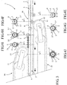
- the machine 1 is partially illustrated in the accompanying figures to show only the parts concerned by the present invention, without chassis or fairing to facilitate understanding.
- This machine allows the manufacture of tubular bodies of boxes, in particular based on cardboard or the like, for example for the packaging of foodstuffs or the like, by unwinding in the longitudinal direction of one or more strips of material 2 wound in coils, said strips being glued, superimposed in plies and slightly offset laterally between them before being applied against a longitudinal forming mandrel 3 around which they are folded, pressed and rolled to form a tubular section 4 closed by one or more longitudinal joints 5 staggered .
- This tubular section 4 is then cut to form said tubular bodies of boxes to the desired dimensions.
- the longitudinal joint 5 is obtained by gluing the superposed longitudinal edges 6 of each strip of material 2, the longitudinal edges of each strip of material being preferably offset laterally so that the longitudinal joints of said strips of material overlap so as not to weaken the wall of the tubular bodies of boxes in this junction zone. If the tubular bodies of boxes are made from a single strip of material, then it is a strip of complex or composite material, that is to say formed of several layers of different materials or not. function of the physical properties that the tubular bodies of boxes must present.
- the machine 1 partially shown in the accompanying figures comprises a longitudinal forming mandrel 3 of circular section corresponding to the inner section of the tubular bodies of boxes to manufacture, which are therefore cylindrical.
- this machine 1 allows the manufacture of tubular bodies of boxes of all sections, such as polygonal, ovoid or other.
- the machine 1 according to the invention differs from known machines in that the "rolling" function of the material strips around the forming mandrel 3 and the “pulling" function of the tubular section formed by said strips of material are dissociated and made by traction means 10 and completely separate pressure means 20.
- the traction means 10 visible on the figures 1 and 3 are preferably arranged downstream of the pressure means 20, that is to say after the formation and closure of the tubular section 4 obtained by the folding and rolling of the material strips 2. They comprise one and preferably several traction belts 11 closed loop around at least two drive rollers 12, at least one is rotated by a suitable actuator such as a motor or servomotor. To ensure a uniformly distributed tensile force on the tubular section 4, four traction belts 11 distributed symmetrically about said forming mandrel 3 are used as in the example shown.
- the profile of the traction belts 11 and the drive rollers 12 is adapted and complementary to the sector of the forming mandrel 3 against which they are supported. In the example shown, this profile is cylindrical.
- the number of traction belts 11 can vary, as well as their layout, their design and their drive means.
- the pressure means 20 comprise a plurality of pressure rollers 21 mounted free to rotate about their axis, deformable and distributed radially and longitudinally around the forming mandrel 3 so as to perfectly fit the entire perimeter of the forming mandrel 3 to ensure a uniform and powerful rolling of the web of material strips 2 against the forming mandrel 3 promoting their cohesion and intimate assembly by gluing.
- Each pressure roller 21 comprises a shaft 22 carrying a lining 23 made of an elastic material, such as for example natural rubbers and synthetic rubbers based on polyurethane, having a given hardness by way of non-limiting example of about 60 Shore.
- the profile of this trim 23 is adapted and complementary to the sector of the forming mandrel 3 against which the pressure roller 21 is applied. In the example shown in Figures 5 and 6 this profile is cylindrical and its radius is less than or equal to that of the forming mandrel 3.
- the pressure rollers used may be pressing rollers 21 which are thus symmetrical, such as those illustrated in FIGS.
- FIGS. Figures 4F, 4G and 4H Their design and operation, however, remain the same.
- the pressure roller 21 When the pressure roller 21 is not pressurized against the forming mandrel 3, it defines a clearance J between its lining 23 which is not stressed and the tubular section 4 carried by the forming mandrel 3 (see FIG. Figure 5A ). When it is pressurized against the forming mandrel 3 by the means described hereinafter, its lining 23 is deformed to eliminate the clearance J and perfectly match the sector of the tubular section 4 against which it bears, the sector of the corresponding forming mandrel 3 behaving in counter-bearing part (see Figure 5B ).
- the pressure roller 21 has the advantage of providing a bearing surface limited to a generator, and therefore to a linear contact, thus making it possible to exert a greater and more uniform local pressure than in the case of a rolling surface. .
- the lining 23 may comprise internal recesses 23 'arranged to increase its elasticity.
- the pressure roller 21 is rotatably mounted on its axis and generates no friction or slippage on the tubular section 4. To reduce or eliminate the differential speeds in the end zones of the pressure roller 21, the size of these pressure rollers 21 is reduced and their number increased.
- the shank 22 of the pressure roller 21 is rotatably mounted on an axis 24 by ball bearings 25 or the like, which axis 24 is carried by a support 26.
- This support 26 comprises a plate 27 fixed to the frame (not shown) of the machine 1 of in order to be dismountable and adjustable in radial position relative to the forming mandrel 3, thus facilitating the maintenance and adjustment operations.
- This support 26 comprises a slider 28 guided in translation in the plate 27 and at the end of which is fixed said pin 24 carrying the pressing roller 21.
- This slider 28 is displaced in radial translation with respect to the forming mandrel 3 by means of a linear actuator, such as a cylinder (not shown), for applying the pressure roller 21 against the forming mandrel 3 with a defined and adjustable pressure.
- This slider 28 comprises at least two guide columns 29, located symmetrically with respect to a central rod 30 extending the linear actuator, the two columns 29 and the central rod 30 being arranged to slide in corresponding bores provided in the plate 27.
- any other equivalent means for guiding and / or pressurizing the pressure rollers 21 is conceivable.
- the machine 1 comprises a centering mandrel 40 ( Figures 2 and 4B ) longitudinal disposed upstream of the forming mandrel 3 against which are fed the strips of material 2 which are unwound from their coils, previously glued, superimposed in a sheet with a small lateral offset as explained above and moved longitudinally by the traction means 10 previously described.
- the strips of material 2 will automatically curve without a lateral guide ( Figure 4A ) since they are placed in longitudinal tension by the pulling means 10 from their unwinding zone to the forming mandrel 3 where they pass from an open state to a flat state in a closed state wound into a tubular section 4.
- the centering mandrel 40 has a polygonal section whose development is inferior to the inner development of the tubular bodies of boxes to manufacture, whose function is to guide longitudinally and transversely the web of strips of material 2 without sliding, thus, the offset side imposed between the strips of material 2 is preserved, which ensures the quality of the longitudinal junction zone of the tubular section 4 and the resistance mechanical tubular bodies of manufactured boxes.
- the shape of the centering mandrel 40 shown may be different, the main thing being to stabilize the web of strips of material 2 which begins to bend by at least one longitudinal angular zone transversely locking the strips of material 2 between them.
- a longitudinal mandrel 41 disposed downstream of the centering mandrel 40 and upstream of the forming mandrel 3 may be provided when it is necessary to weld a barrier film forming a membrane or inner layer provided in the tubular bodies of boxes to be manufactured for to respect sealing constraints.
- this temporary mandrel 41 has a section in the form of a drop of water whose developed corresponds to the internal development D of the tubular bodies of boxes to be manufactured ( Figures 2 and 4C ).
- Cylindrical pressing rollers are provided in abutment on the inclined and opposite sides of the temporary mandrel 41 to press the barrier film around said mandrel and pull it upwards to perform the welding operation by an adjacent welding station 42 chuck and using for example ultrasound or the like. If the barrier film is to be glued instead of welded, the temporary mandrel 41 is not useful. By cons, a gluing nozzle (not shown) is placed at this level to deposit glue on at least one of the longitudinal edges of said barrier film before folding with the other strips of material 2. In other cases , the tubular bodies of boxes may be devoid of barrier film.
- the sheet of material strips 2 is folded laterally by a flanging roller 43 offering a profile complementary to the provisional half mandrel 41 or centering mandrel 40 ( Figures 2 and 4D ).
- This folding roller 43 is rotatably mounted on its axis to prevent any friction on the web.
- the machine 1 can advantageously be completed by a gluing nozzle 44 arranged facing the edges longitudinals 6 offset strips of material 2 to add glue on these areas that tend to air dry.
- this gluing nozzle 44 thus makes it possible to substantially reduce the quantity of glue between the strips of material 2, which are previously glued individually in a gluing station (not shown) before being superimposed on a sheet, and consequently reduce the residual moisture of the box bodies produced.
- the fact of adding glue just before folding down the longitudinal edges 6 of the strips of material 2 has the advantage of allowing quality and uniform gluing along the entire longitudinal joint 5.
- the pressure rollers 21 forming the pressing means 20 for shaping and rolling the web of material strips 2 around said mandrel are distributed symmetrically with respect to said mandrel, its lower part ( figure 4E ) against which the sheet arrives, at its upper part ( figure 4I against which the sheet closes to form the tubular section 4.
Claims (15)
- Maschine (1) zur kontinuierlichen Herstellung von rohrförmigen Behältern, insbesondere auf Basis von Karton oder dergleichen, wobei diese Maschine zumindest einen longitudinalen Formdorn (3) beträgt, dessen Querschnitt dem inneren Querschnitt der herzustellenden rohrförmigen Behältern entspricht und um welchen zumindest einen in Längsrichtung abgerollten und vorher zumindest zum Teil mit Klebstoff versehenen Materialstreifen (2) angebracht und umgeschlagen wird, um ein geschlossenes Rohrprofil (4) zu formen, wobei diese Maschine zudem Druckmittel (20) beträgt, die ausgelegt sind, um besagten zumindest einen Materialstreifen (2) gegen besagten Formdorm (3) zu walzen, sowie Zugmittel (10), die ausgelegt sind, um besagtes Rohrprofil (4) kontinuierlich entlang besagtem Formdorn (3) zu bewegen, dadurch gekennzeichnet, dass besagte Druckmittel (20) und besagte Zugmittel (10) getrennt sind, und dadurch, dass besagte Druckmittel (20) eine Vielzahl frei um ihre Achse drehbare Andruckrollen (21, 21') betragen, wobei besagte Andruckrollen verformbar sind und radial um besagten Formdorn (3) verteilt sind, um sich an den Umfang von besagtem Dorn anzuschmiegen.
- Maschine nach Anspruch 1, dadurch gekennzeichnet, dass besagte Andruckrollen (21, 21') symmetrisch um besagten Formdorn (3) verteilt sind, jeweils einen Sektor von besagtem Dorn abdecken, und in Längsrichtung versetzt sind, um den ganzen Umfang von besagtem Dorn abzudecken.
- Maschine nach einem der Ansprüche 1 und 2, dadurch gekennzeichnet, dass jede Andruckrolle (21, 21') einen aus einem elastischen Material hergestellten Belag (23) aufweist.
- Maschine nach Anspruch 3, dadurch gekennzeichnet, dass der elastische Belag (23) jeder Andruckrolle (21, 21') ein Profil aufweist, das zu dem Profil des Sektors des besagten Formdorns (3), gegen den die entsprechende Andruckrolle gepresst wird, komplementär ist.
- Maschine nach Anspruch 3, dadurch gekennzeichnet, dass besagter elastische Belag (23) innere Aushöhlungen (23') beträgt, die ausgelegt sind, um seine Elastizität zu erhöhen.
- Maschine nach Anspruch 3, dadurch gekennzeichnet, dass das elastische Material von besagtem Belag in der Gruppe gewählt wird, die die natürlichen Kautschuke und die Kunstkautschuke auf Polyurethan-Basis umfasst.
- Maschine nach Anspruch 1, dadurch gekennzeichnet, dass jede Andruckrolle (21, 21') von einem Träger (26) getragen wird, dessen Radiallage in Bezug auf besagten Formdorm (3) verstellbar ist.
- Maschine nach Anspruch 7, dadurch gekennzeichnet, dass jede Andruckrolle (21, 21') an ein auf besagtem Träger (26) angeordnetes Druckbeaufschlagungsmittel gekoppelt ist.
- Maschine nach einem beliebigen der vorhergehenden Ansprüche, dadurch gekennzeichnet, dass sie zudem einen vor besagtem Formdorn (3) angeordneten longitudinalen Zentrierdorn (40) beträgt, der einen polygonalen Querschnitt aufweist, dessen Abwicklung kleiner ist, als die Innenabwicklung der herzustellenden rohrförmigen Behälter, wobei besagter Zentrierdorn (40) ausgelegt ist, um besagte Materielstreifen (2) ohne Verschiebung in Längs- und in Quer-Richtung zu führen.
- Maschine nach Anspruch 9, dadurch gekennzeichnet, dass sie zudem einen nach besagtem Zentrierdorn (40) und vor besagtem Formdorn (3) angeordneten longitudinalen Hilfsdorn (41) beträgt, der einen wassertropfenförmigen Querschnitt aufweist, dessen Abwicklung der Innenabwicklung (D) der herzustellenden rohrförmigen Behälter entspricht.
- Maschine nach Anspruch 10, dadurch gekennzeichnet, dass sie eine an besagtem Hilfsdorn (41) anliegende Schweiß-Station (42) beträgt, um die Längsränder von zumindest einem Materialstreifen zu schweißen, der die Innenlage von besagten rohrförmigen Behältern bildet.
- Maschine nach einem beliebigen der vorhergehenden Ansprüche, dadurch gekennzeichnet, dass sie zudem eine Reihe Andruckrollen (21) beträgt, die auf einem Längssektor von besagtem Formdorn (3) ausgerichtet sind, der einem Bereich entspricht, in dem sich die Seitenränder von besagtem zumindest einem Materialstreifen (2) zusammenfügen, um besagtes Rohrprofil (4) durch zumindest eine Längsverbindung zu schließen.
- Maschine nach einem beliebigen der vorhergehenden Ansprüche, dadurch gekennzeichnet, dass besagte Zugmittel (10) zumindest einen von Antriebsrollen (12) getragenen Zugriemen (11) betragen, der nach besagten Druckmitteln (20) angeordnet ist.
- Maschine nach Anspruch 13, dadurch gekennzeichnet, dass besagte Zugmittel (10) zumindest zwei symmetrisch in Bezug auf besagten Formdorn (3) angeordnete Zugriemen (11) betragen.
- Maschine nach einem beliebigen der vorhergehenden Ansprüche, dadurch gekennzeichnet, dass sie zumindest eine Klebstoffdüse (44) beträgt, die ausgelegt ist, um Klebstoff zumindest auf gewisse der Längsränder von besagten Materialstreifen (2) aufzutragen.
Priority Applications (1)
| Application Number | Priority Date | Filing Date | Title |
|---|---|---|---|
| PL14727575T PL2988928T3 (pl) | 2013-04-22 | 2014-04-09 | Maszyna do wytwarzania w sposób ciągły rurowych korpusów pudeł, zwłaszcza na bazie tektury lub podobnego materiału |
Applications Claiming Priority (2)
| Application Number | Priority Date | Filing Date | Title |
|---|---|---|---|
| FR1353638A FR3004671B1 (fr) | 2013-04-22 | 2013-04-22 | Machine pour la fabrication en continu de corps tubulaires de boites notamment a base de carton ou similaire |
| PCT/FR2014/000082 WO2014174161A1 (fr) | 2013-04-22 | 2014-04-09 | Machine pour la fabrication en continu de corps tubulaires de boites notamment a base de carton ou similaire |
Publications (2)
| Publication Number | Publication Date |
|---|---|
| EP2988928A1 EP2988928A1 (de) | 2016-03-02 |
| EP2988928B1 true EP2988928B1 (de) | 2017-06-14 |
Family
ID=48656177
Family Applications (1)
| Application Number | Title | Priority Date | Filing Date |
|---|---|---|---|
| EP14727575.4A Active EP2988928B1 (de) | 2013-04-22 | 2014-04-09 | Maschine zur kontinuierlichen herstellung von rohrförmigen behältern, insbesondere auf basis von karton oder dergleichen |
Country Status (10)
| Country | Link |
|---|---|
| US (1) | US20160082686A1 (de) |
| EP (1) | EP2988928B1 (de) |
| JP (1) | JP6425145B2 (de) |
| CA (1) | CA2911842A1 (de) |
| ES (1) | ES2639466T3 (de) |
| FR (1) | FR3004671B1 (de) |
| PL (1) | PL2988928T3 (de) |
| PT (1) | PT2988928T (de) |
| RU (1) | RU2649300C2 (de) |
| WO (1) | WO2014174161A1 (de) |
Families Citing this family (2)
| Publication number | Priority date | Publication date | Assignee | Title |
|---|---|---|---|---|
| IT201900009162A1 (it) | 2019-06-17 | 2020-12-17 | Engraving Solutions S R L | Metodo e macchina per produrre rotoli di materiale nastriforme avvolto su anime tubolari e relativo prodotto ottenuto |
| IT202100008879A1 (it) * | 2021-04-09 | 2022-10-09 | Comec Srl | Impianto in continuo per la formatura di un elemento tubolare a partire da un nastro piano di materiale cartaceo e relativo metodo |
Family Cites Families (35)
| Publication number | Priority date | Publication date | Assignee | Title |
|---|---|---|---|---|
| US3124872A (en) * | 1964-03-17 | Method and apparatus for severing a continuous | ||
| US3338142A (en) * | 1967-08-29 | Method and machine for making tubular container bodies | ||
| US1761980A (en) * | 1927-07-05 | 1930-06-03 | Bundy Tubing Co | Method of making finned tubing |
| US1983361A (en) * | 1933-10-27 | 1934-12-04 | Boothby Fibre Can Company | Container made of paper and method of producing it |
| US2016273A (en) * | 1934-09-14 | 1935-10-08 | Harry N Atwood | Built-up composite cellular structure |
| US2125758A (en) * | 1935-05-08 | 1938-08-02 | Harry F Waters | Machine for manufacturing bags |
| US2148884A (en) * | 1935-06-05 | 1939-02-28 | Ind Patents Corp | Method for forming synthetic sausage casings |
| US2256263A (en) * | 1940-10-10 | 1941-09-16 | Continental Can Co | Method of and apparatus for forming paper container bodies |
| US3623929A (en) * | 1966-10-07 | 1971-11-30 | Int Paper Co | Method for producing spiral wound container |
| US3908526A (en) * | 1971-07-08 | 1975-09-30 | Venizelos Vassalos | Machine and method to produce fiberboard tubes of polygonal cross-section |
| US4198739A (en) * | 1976-05-19 | 1980-04-22 | Rodel, Inc. | Printing roller with polymeric coner and method of making the same |
| DE2837184A1 (de) * | 1978-08-25 | 1980-03-06 | Kabel Metallwerke Ghh | Verfahren und vorrichtung zur herstellung von rohren fuer waermetauscher |
| US4528053A (en) * | 1982-09-29 | 1985-07-09 | Auer Mark J | Manufacturing fiberboard ducts |
| US4629529A (en) * | 1984-10-22 | 1986-12-16 | Steeltin Can Corporation | Method and machine for convolute or spiral winding of composite materials |
| JPH0796262B2 (ja) * | 1987-03-14 | 1995-10-18 | 北海製罐株式会社 | 管状体の成形方法及びその装置 |
| JPH0452047Y2 (de) * | 1987-07-03 | 1992-12-08 | ||
| JPS6457925A (en) * | 1987-08-28 | 1989-03-06 | Toshiba Corp | Production of spiral body |
| DE3851403T2 (de) * | 1987-10-14 | 1995-01-19 | Canon Kk | Bildfixierwalze und Bildfixiergerät mit dieser Walze. |
| JP2566444B2 (ja) * | 1988-05-30 | 1996-12-25 | 北海製罐株式会社 | 複合管状体の成形方法 |
| DE3915508A1 (de) * | 1989-05-12 | 1990-11-15 | Feldmuehle Ag | Walze zur druckbehandlung von warenbahnen |
| GB9201096D0 (en) * | 1992-01-20 | 1992-03-11 | Unilever Plc | Tube-forming apparatus |
| FR2702414B1 (fr) * | 1993-03-12 | 1996-07-05 | Helverep Sa | Procédé de fabrication en continu de corps tubulaires de boîtes notamment en carton. |
| SE9503560D0 (sv) * | 1995-10-11 | 1995-10-11 | Ingmar Andreasson | Lastpall |
| AUPO221796A0 (en) * | 1996-09-09 | 1996-10-03 | Acworth, Arthur Keith | Improvements to weights and sinkers |
| US5829669A (en) * | 1997-02-06 | 1998-11-03 | Sonoco Products Company | Tubular container and methods and apparatus for manufacturing same |
| US5707329A (en) * | 1997-02-11 | 1998-01-13 | Pool; George H. | Narrow profile apparatus for forming tubes from plastic web stock |
| FR2763888B1 (fr) * | 1997-05-28 | 1999-07-16 | Rollin Sa | Manchon perfectionne pour cylindre de machine d'impression ou analogue et procede de mise en place de ce manchon |
| ES1049406Y (es) * | 2001-06-15 | 2002-04-16 | Roca Ramon Valls | Tubo de carton para hilados. |
| DE10261985A1 (de) * | 2002-09-21 | 2004-04-08 | Koenig & Bauer Ag | Vorrichtung zum Einstellen des Anpressdrucks einer verstellbar gelagerten Walze |
| US20040121891A1 (en) * | 2002-12-19 | 2004-06-24 | Sonoco Development, Inc. | Stage cut patterns for linear drawn composite containers |
| FI117280B (fi) * | 2003-01-10 | 2006-08-31 | Metso Paper Inc | Menetelmä kuljettimen yhteydessä ja kuljetin |
| US20070125474A1 (en) * | 2005-12-05 | 2007-06-07 | Huber Engineered Woods L.L.C. | Handheld tape applicator and components thereof, and their methods of use |
| US8167782B2 (en) * | 2007-02-16 | 2012-05-01 | Linzer Products Corp. | Method and apparatus for making a paint roller and product produced thereby |
| JP6041623B2 (ja) * | 2012-10-29 | 2016-12-14 | キヤノン株式会社 | 定着部材及びその製造方法 |
| CN105799217A (zh) * | 2016-03-16 | 2016-07-27 | 稳健医疗用品股份有限公司 | 无纺布环保袋制造方法及制造设备 |
-
2013
- 2013-04-22 FR FR1353638A patent/FR3004671B1/fr active Active
-
2014
- 2014-04-09 PT PT147275754T patent/PT2988928T/pt unknown
- 2014-04-09 RU RU2015149765A patent/RU2649300C2/ru active
- 2014-04-09 US US14/785,444 patent/US20160082686A1/en not_active Abandoned
- 2014-04-09 JP JP2016508205A patent/JP6425145B2/ja active Active
- 2014-04-09 ES ES14727575.4T patent/ES2639466T3/es active Active
- 2014-04-09 PL PL14727575T patent/PL2988928T3/pl unknown
- 2014-04-09 CA CA2911842A patent/CA2911842A1/fr not_active Abandoned
- 2014-04-09 EP EP14727575.4A patent/EP2988928B1/de active Active
- 2014-04-09 WO PCT/FR2014/000082 patent/WO2014174161A1/fr active Application Filing
Non-Patent Citations (1)
| Title |
|---|
| None * |
Also Published As
| Publication number | Publication date |
|---|---|
| EP2988928A1 (de) | 2016-03-02 |
| ES2639466T3 (es) | 2017-10-26 |
| JP6425145B2 (ja) | 2018-11-21 |
| JP2016516614A (ja) | 2016-06-09 |
| US20160082686A1 (en) | 2016-03-24 |
| CA2911842A1 (fr) | 2014-10-30 |
| RU2649300C2 (ru) | 2018-03-30 |
| PT2988928T (pt) | 2017-09-12 |
| RU2015149765A (ru) | 2017-05-26 |
| FR3004671B1 (fr) | 2015-05-22 |
| WO2014174161A1 (fr) | 2014-10-30 |
| FR3004671A1 (fr) | 2014-10-24 |
| PL2988928T3 (pl) | 2017-12-29 |
Similar Documents
| Publication | Publication Date | Title |
|---|---|---|
| EP2782840B1 (de) | Vorrichtung zum verschliessen von beuteln mit berührungs- und klangfunktionen sowie beutel mit einer solchen vorrichtung | |
| EP0300855B1 (de) | Band mit Längsverstärkung, seine Herstellung und seine Verwendung im Verpackungsverfahren und Vorrichtung zur Herstellung eines solchen Bandes | |
| EP1679265A1 (de) | Tube mit nichtkreisförmigem Querschnitt, Verfahren zu deren Herstellung und Vorrichtung dafür | |
| EP2988928B1 (de) | Maschine zur kontinuierlichen herstellung von rohrförmigen behältern, insbesondere auf basis von karton oder dergleichen | |
| FR2702414A1 (fr) | Procédé de fabrication en continu de corps tubulaires de boîtes notamment en carton. | |
| EP2188110B1 (de) | Verfahren zur herstellung von rohren durch schweissen | |
| FR2484328A1 (fr) | Machine de fabrication de carton ondule | |
| FR2756339A1 (fr) | Arbre expansible pour appareil d'enroulement de bandes | |
| EP2613929B1 (de) | Verfahren zur herstellung eines reifenrohlings mit einem nähschritt | |
| EP1747158B1 (de) | Verfahren zur herstellung einer zentralen abwickelrolle und rolle | |
| EP2145755A1 (de) | Verfahren zur Formung von Winkelprofilen und Vorrichtung zur Umsetzung dieses Verfahrens | |
| FR2876365A1 (fr) | Procede et dispositif d'enroulement en bobine d'une bande | |
| EP3160724B1 (de) | Verfahren und vorrichtung zur herstellung eines reifenrohlings | |
| FR2846954A1 (fr) | Procede de faconnage de bobines de bandes de papier, bobines obtenues par ce procede, et machine pour la mise en oeuvre de ce procede | |
| EP2254746B1 (de) | Verfahren und Vorrichtung zur Herstellung einer Verstärkung durch Wickeln eines Bands auf sich selbst | |
| FR2628029A1 (fr) | Dispositif d'etirage d'un film de matiere plastique | |
| FR2688738A1 (fr) | Procede de fabrication d'un ou de plusieurs profiles en matiere flexible, en particulier en papier, en carton, en materiaux composites ou analogues et dispositif pour la mise en óoeuvre de ce procede. | |
| BE1006210A6 (fr) | Dispositif de separation de feuilles assemblees avec une pellicule continue. | |
| WO2021084191A1 (fr) | Procédé et dispositif pour la fabrication d'un filtre conique | |
| EP0921938A1 (de) | Maschine und vorrichtung zum herstellen von einseitiger wellpappe unter verwendung von reibförderung | |
| CA2260260A1 (fr) | Carton ondule rigide | |
| FR2974820A1 (fr) | Rouleau pour tete d'etancheite et procede de fabrication | |
| CH312220A (fr) | Appareil pour effectuer le pliage préalable d'ébauches en carton. | |
| WO2013124549A1 (fr) | Procede de fabrication d'un profile tubulaire. profile tubulaire obtenu et utilisation dudit profile tubulaire | |
| CH264311A (fr) | Procédé de fabrication d'un sac en papier et matières analogues, et appareil pour la mise en oeuvre dudit procédé. |
Legal Events
| Date | Code | Title | Description |
|---|---|---|---|
| PUAI | Public reference made under article 153(3) epc to a published international application that has entered the european phase |
Free format text: ORIGINAL CODE: 0009012 |
|
| 17P | Request for examination filed |
Effective date: 20151019 |
|
| AK | Designated contracting states |
Kind code of ref document: A1 Designated state(s): AL AT BE BG CH CY CZ DE DK EE ES FI FR GB GR HR HU IE IS IT LI LT LU LV MC MK MT NL NO PL PT RO RS SE SI SK SM TR |
|
| AX | Request for extension of the european patent |
Extension state: BA ME |
|
| DAX | Request for extension of the european patent (deleted) | ||
| GRAP | Despatch of communication of intention to grant a patent |
Free format text: ORIGINAL CODE: EPIDOSNIGR1 |
|
| INTG | Intention to grant announced |
Effective date: 20170119 |
|
| RIC1 | Information provided on ipc code assigned before grant |
Ipc: B31F 7/00 20060101ALI20170117BHEP Ipc: B31B 50/28 20170101ALI20170117BHEP Ipc: B31F 1/00 20060101AFI20170117BHEP |
|
| GRAJ | Information related to disapproval of communication of intention to grant by the applicant or resumption of examination proceedings by the epo deleted |
Free format text: ORIGINAL CODE: EPIDOSDIGR1 |
|
| GRAJ | Information related to disapproval of communication of intention to grant by the applicant or resumption of examination proceedings by the epo deleted |
Free format text: ORIGINAL CODE: EPIDOSDIGR1 |
|
| GRAP | Despatch of communication of intention to grant a patent |
Free format text: ORIGINAL CODE: EPIDOSNIGR1 |
|
| GRAS | Grant fee paid |
Free format text: ORIGINAL CODE: EPIDOSNIGR3 |
|
| INTC | Intention to grant announced (deleted) | ||
| GRAR | Information related to intention to grant a patent recorded |
Free format text: ORIGINAL CODE: EPIDOSNIGR71 |
|
| GRAS | Grant fee paid |
Free format text: ORIGINAL CODE: EPIDOSNIGR3 |
|
| GRAA | (expected) grant |
Free format text: ORIGINAL CODE: 0009210 |
|
| INTG | Intention to grant announced |
Effective date: 20170504 |
|
| AK | Designated contracting states |
Kind code of ref document: B1 Designated state(s): AL AT BE BG CH CY CZ DE DK EE ES FI FR GB GR HR HU IE IS IT LI LT LU LV MC MK MT NL NO PL PT RO RS SE SI SK SM TR |
|
| REG | Reference to a national code |
Ref country code: GB Ref legal event code: FG4D Free format text: NOT ENGLISH |
|
| REG | Reference to a national code |
Ref country code: CH Ref legal event code: EP Ref country code: AT Ref legal event code: REF Ref document number: 900550 Country of ref document: AT Kind code of ref document: T Effective date: 20170615 |
|
| REG | Reference to a national code |
Ref country code: IE Ref legal event code: FG4D Free format text: LANGUAGE OF EP DOCUMENT: FRENCH |
|
| REG | Reference to a national code |
Ref country code: DE Ref legal event code: R096 Ref document number: 602014010787 Country of ref document: DE |
|
| REG | Reference to a national code |
Ref country code: CH Ref legal event code: NV Representative=s name: CABINET ROLAND NITHARDT CONSEILS EN PROPRIETE , CH |
|
| REG | Reference to a national code |
Ref country code: PT Ref legal event code: SC4A Ref document number: 2988928 Country of ref document: PT Date of ref document: 20170912 Kind code of ref document: T Free format text: AVAILABILITY OF NATIONAL TRANSLATION Effective date: 20170901 |
|
| REG | Reference to a national code |
Ref country code: NL Ref legal event code: FP |
|
| REG | Reference to a national code |
Ref country code: LT Ref legal event code: MG4D |
|
| REG | Reference to a national code |
Ref country code: ES Ref legal event code: FG2A Ref document number: 2639466 Country of ref document: ES Kind code of ref document: T3 Effective date: 20171026 |
|
| PG25 | Lapsed in a contracting state [announced via postgrant information from national office to epo] |
Ref country code: GR Free format text: LAPSE BECAUSE OF FAILURE TO SUBMIT A TRANSLATION OF THE DESCRIPTION OR TO PAY THE FEE WITHIN THE PRESCRIBED TIME-LIMIT Effective date: 20170915 Ref country code: FI Free format text: LAPSE BECAUSE OF FAILURE TO SUBMIT A TRANSLATION OF THE DESCRIPTION OR TO PAY THE FEE WITHIN THE PRESCRIBED TIME-LIMIT Effective date: 20170614 Ref country code: LT Free format text: LAPSE BECAUSE OF FAILURE TO SUBMIT A TRANSLATION OF THE DESCRIPTION OR TO PAY THE FEE WITHIN THE PRESCRIBED TIME-LIMIT Effective date: 20170614 Ref country code: HR Free format text: LAPSE BECAUSE OF FAILURE TO SUBMIT A TRANSLATION OF THE DESCRIPTION OR TO PAY THE FEE WITHIN THE PRESCRIBED TIME-LIMIT Effective date: 20170614 Ref country code: NO Free format text: LAPSE BECAUSE OF FAILURE TO SUBMIT A TRANSLATION OF THE DESCRIPTION OR TO PAY THE FEE WITHIN THE PRESCRIBED TIME-LIMIT Effective date: 20170914 |
|
| REG | Reference to a national code |
Ref country code: AT Ref legal event code: MK05 Ref document number: 900550 Country of ref document: AT Kind code of ref document: T Effective date: 20170614 |
|
| PG25 | Lapsed in a contracting state [announced via postgrant information from national office to epo] |
Ref country code: SE Free format text: LAPSE BECAUSE OF FAILURE TO SUBMIT A TRANSLATION OF THE DESCRIPTION OR TO PAY THE FEE WITHIN THE PRESCRIBED TIME-LIMIT Effective date: 20170614 Ref country code: RS Free format text: LAPSE BECAUSE OF FAILURE TO SUBMIT A TRANSLATION OF THE DESCRIPTION OR TO PAY THE FEE WITHIN THE PRESCRIBED TIME-LIMIT Effective date: 20170614 Ref country code: LV Free format text: LAPSE BECAUSE OF FAILURE TO SUBMIT A TRANSLATION OF THE DESCRIPTION OR TO PAY THE FEE WITHIN THE PRESCRIBED TIME-LIMIT Effective date: 20170614 Ref country code: BG Free format text: LAPSE BECAUSE OF FAILURE TO SUBMIT A TRANSLATION OF THE DESCRIPTION OR TO PAY THE FEE WITHIN THE PRESCRIBED TIME-LIMIT Effective date: 20170914 |
|
| PG25 | Lapsed in a contracting state [announced via postgrant information from national office to epo] |
Ref country code: RO Free format text: LAPSE BECAUSE OF FAILURE TO SUBMIT A TRANSLATION OF THE DESCRIPTION OR TO PAY THE FEE WITHIN THE PRESCRIBED TIME-LIMIT Effective date: 20170614 Ref country code: CZ Free format text: LAPSE BECAUSE OF FAILURE TO SUBMIT A TRANSLATION OF THE DESCRIPTION OR TO PAY THE FEE WITHIN THE PRESCRIBED TIME-LIMIT Effective date: 20170614 Ref country code: SK Free format text: LAPSE BECAUSE OF FAILURE TO SUBMIT A TRANSLATION OF THE DESCRIPTION OR TO PAY THE FEE WITHIN THE PRESCRIBED TIME-LIMIT Effective date: 20170614 Ref country code: EE Free format text: LAPSE BECAUSE OF FAILURE TO SUBMIT A TRANSLATION OF THE DESCRIPTION OR TO PAY THE FEE WITHIN THE PRESCRIBED TIME-LIMIT Effective date: 20170614 Ref country code: AT Free format text: LAPSE BECAUSE OF FAILURE TO SUBMIT A TRANSLATION OF THE DESCRIPTION OR TO PAY THE FEE WITHIN THE PRESCRIBED TIME-LIMIT Effective date: 20170614 |
|
| PG25 | Lapsed in a contracting state [announced via postgrant information from national office to epo] |
Ref country code: IS Free format text: LAPSE BECAUSE OF FAILURE TO SUBMIT A TRANSLATION OF THE DESCRIPTION OR TO PAY THE FEE WITHIN THE PRESCRIBED TIME-LIMIT Effective date: 20171014 Ref country code: SM Free format text: LAPSE BECAUSE OF FAILURE TO SUBMIT A TRANSLATION OF THE DESCRIPTION OR TO PAY THE FEE WITHIN THE PRESCRIBED TIME-LIMIT Effective date: 20170614 |
|
| REG | Reference to a national code |
Ref country code: DE Ref legal event code: R097 Ref document number: 602014010787 Country of ref document: DE |
|
| PLBE | No opposition filed within time limit |
Free format text: ORIGINAL CODE: 0009261 |
|
| STAA | Information on the status of an ep patent application or granted ep patent |
Free format text: STATUS: NO OPPOSITION FILED WITHIN TIME LIMIT |
|
| REG | Reference to a national code |
Ref country code: FR Ref legal event code: PLFP Year of fee payment: 5 |
|
| PG25 | Lapsed in a contracting state [announced via postgrant information from national office to epo] |
Ref country code: DK Free format text: LAPSE BECAUSE OF FAILURE TO SUBMIT A TRANSLATION OF THE DESCRIPTION OR TO PAY THE FEE WITHIN THE PRESCRIBED TIME-LIMIT Effective date: 20170614 |
|
| 26N | No opposition filed |
Effective date: 20180315 |
|
| PG25 | Lapsed in a contracting state [announced via postgrant information from national office to epo] |
Ref country code: SI Free format text: LAPSE BECAUSE OF FAILURE TO SUBMIT A TRANSLATION OF THE DESCRIPTION OR TO PAY THE FEE WITHIN THE PRESCRIBED TIME-LIMIT Effective date: 20170614 |
|
| PG25 | Lapsed in a contracting state [announced via postgrant information from national office to epo] |
Ref country code: MT Free format text: LAPSE BECAUSE OF FAILURE TO SUBMIT A TRANSLATION OF THE DESCRIPTION OR TO PAY THE FEE WITHIN THE PRESCRIBED TIME-LIMIT Effective date: 20170614 |
|
| PG25 | Lapsed in a contracting state [announced via postgrant information from national office to epo] |
Ref country code: MC Free format text: LAPSE BECAUSE OF FAILURE TO SUBMIT A TRANSLATION OF THE DESCRIPTION OR TO PAY THE FEE WITHIN THE PRESCRIBED TIME-LIMIT Effective date: 20170614 |
|
| REG | Reference to a national code |
Ref country code: IE Ref legal event code: MM4A |
|
| PG25 | Lapsed in a contracting state [announced via postgrant information from national office to epo] |
Ref country code: LU Free format text: LAPSE BECAUSE OF NON-PAYMENT OF DUE FEES Effective date: 20180409 |
|
| PG25 | Lapsed in a contracting state [announced via postgrant information from national office to epo] |
Ref country code: IE Free format text: LAPSE BECAUSE OF NON-PAYMENT OF DUE FEES Effective date: 20180409 |
|
| PG25 | Lapsed in a contracting state [announced via postgrant information from national office to epo] |
Ref country code: CY Free format text: LAPSE BECAUSE OF FAILURE TO SUBMIT A TRANSLATION OF THE DESCRIPTION OR TO PAY THE FEE WITHIN THE PRESCRIBED TIME-LIMIT Effective date: 20170614 Ref country code: HU Free format text: LAPSE BECAUSE OF FAILURE TO SUBMIT A TRANSLATION OF THE DESCRIPTION OR TO PAY THE FEE WITHIN THE PRESCRIBED TIME-LIMIT; INVALID AB INITIO Effective date: 20140409 Ref country code: MK Free format text: LAPSE BECAUSE OF NON-PAYMENT OF DUE FEES Effective date: 20170614 |
|
| PG25 | Lapsed in a contracting state [announced via postgrant information from national office to epo] |
Ref country code: AL Free format text: LAPSE BECAUSE OF FAILURE TO SUBMIT A TRANSLATION OF THE DESCRIPTION OR TO PAY THE FEE WITHIN THE PRESCRIBED TIME-LIMIT Effective date: 20170614 |
|
| PGFP | Annual fee paid to national office [announced via postgrant information from national office to epo] |
Ref country code: PT Payment date: 20210316 Year of fee payment: 8 |
|
| PGFP | Annual fee paid to national office [announced via postgrant information from national office to epo] |
Ref country code: TR Payment date: 20210330 Year of fee payment: 8 Ref country code: PL Payment date: 20210322 Year of fee payment: 8 |
|
| PG25 | Lapsed in a contracting state [announced via postgrant information from national office to epo] |
Ref country code: PT Free format text: LAPSE BECAUSE OF NON-PAYMENT OF DUE FEES Effective date: 20221010 |
|
| PGFP | Annual fee paid to national office [announced via postgrant information from national office to epo] |
Ref country code: IT Payment date: 20230417 Year of fee payment: 10 Ref country code: FR Payment date: 20230427 Year of fee payment: 10 Ref country code: ES Payment date: 20230504 Year of fee payment: 10 Ref country code: DE Payment date: 20230412 Year of fee payment: 10 Ref country code: CH Payment date: 20230502 Year of fee payment: 10 |
|
| PG25 | Lapsed in a contracting state [announced via postgrant information from national office to epo] |
Ref country code: PL Free format text: LAPSE BECAUSE OF NON-PAYMENT OF DUE FEES Effective date: 20220409 |
|
| PGFP | Annual fee paid to national office [announced via postgrant information from national office to epo] |
Ref country code: BE Payment date: 20230424 Year of fee payment: 10 |
|
| PGFP | Annual fee paid to national office [announced via postgrant information from national office to epo] |
Ref country code: GB Payment date: 20230424 Year of fee payment: 10 |
|
| PGFP | Annual fee paid to national office [announced via postgrant information from national office to epo] |
Ref country code: NL Payment date: 20240325 Year of fee payment: 11 |